Article

Transceiver Design for GFDM with Hexagonal Time–Frequency Allocation Using the Polyphase Decomposition

Department of Electronic Systems, NTNU Norwegian University of Science and Technology, 2815 Gjøvik, Norway
*
Author to whom correspondence should be addressed.
Electronics 2020, 9(11), 1862; https://doi.org/10.3390/electronics9111862
Submission received: 24 September 2020 / Revised: 2 November 2020 / Accepted: 4 November 2020 / Published: 6 November 2020
(This article belongs to the Section Circuit and Signal Processing)

Abstract

:
Generalized frequency division multiplexing (GFDM) is a waveform for the next-generation communication systems to succeed in the drawbacks of orthogonal frequency division multiplexing (OFDM). The symbols of users are transmitted with the time- and frequency-shifted versions of a prototype filter. According to filtering operation, the computational complexity and processing load are high for the devices that suffer from energy consumption. The communication systems are required to support the new generation devices that need low energy consumption and low latency issues. Motivated by such demands of the next-generation communication system, we propose a novel GFDM waveform that we call hexagonal GFDM. The contributions of the hexagonal GFDM are that it: (i) supports short transmission time based on its hexagonal time–frequency allocations; and (ii) provides low latency communication with low computational complexity manner. Furthermore, we design a transmitter and receiver structure in a less complicated way with mathematical derivation by using polyphase decomposition and Fourier transform (FT) transformation. The proposed systems are realized analytically and investigated over Rayleigh fading channel model through computer simulations.

1. Introduction

The next-generation wireless communication system’s key features include spectral efficiency, high data rate and power consumption with the simple transceiver structure [1,2]. The systems can support non-synchronized users at numbers about 100 times greater than allowed by recent 4G wireless communication networks that have different demands [3,4]. Real-time communication systems, such as tactile Internet, suffer from latency for short transmission time, synchronization for different demands of users and computational complexity issues for power consumption [5,6]. The waveform used in current communication systems is not able to meet the new demands of the 5G and beyond the communication system.
The orthogonal frequency division multiplexing (OFDM) system can prevent interference between symbols and carriers using a cyclic prefix and guard band, respectively. However, any time and frequency variations on the users’ transmission channel and synchronization problems cause the interference between subcarriers and symbols. The new waveforms such as filter bank-based multicarrier (FBMC), generalized frequency division multiplexing (GFDM), universal filtered multicarrier (UFMC) are proposed to solve the drawbacks of the OFDM. Accordingly, FBMC is the waveform that utilizes the low-pass filters, which are shifted in the frequency domain [7,8]. Unlike FBMC, more than one subcarriers are filtered instead of filtering every subcarrier. Moreover, UFMC is another waveform with a lower out-of-band (OOB) emission level similar to GFDM [9,10,11]. GFDM outperforms OFDM in terms of inter-user interference between asynchronous users with frequency and time misalignments [12]. Up to now, the related waveforms are mainly based on the rectangular lattice structure with adopting a pulse shaping. It is known that the pulse shaping methods suffer from filter tailing on time and frequency domain [13]. Therefore, two main solutions are: (i) using a pulse with a good time–frequency localization; and (ii) leaving space between the symbols in the time–frequency lattice points. These solutions can be adopted on a proposed waveform that benefits from the hexagonal lattice points and Gaussian pulses [14]. Accordingly, hexagonal multicarrier transmission outperforms OFDM with respect to robustness against the effects of the channel dispersion. Thus, the hexagonal lattice structures have better performance than conventional OFDM against ISI/ICI effects because of lower energy perturbation [15,16]. Therefore, waveforms containing hexagonal lattice structures have also been proposed for next-generation communication systems. An optimum transceiver structure of FBMC waveform with hexagonal time–frequency allocations is proposed in [17]. Accordingly, hexagonal FBMC is more robust to frequency synchronization errors and offers fewer OOB emissions concerning rectangular FBMC. Moreover, hexagonal Hermite waveforms have many potential benefits for the unsynchronized user at multi-user communications under doubly dispersive channel conditions [18]. On the other hand, fractional Fourier transform, which has equivalent computational complexity with Fourier transform (FT), is used to design a hexagonal frequency lattice structure to provide robustness on noise [19]. Hexagonal nonorthogonal multicarrier modulation is robust when using the Gaussian pulse which is the best time–frequency localized pulse shape [14].
Besides the pulse shaping, time and frequency allocation is an important issue concerning the robustness on double dispersive channels. The Euclidean distance between the transmitted symbols on the time-frequency lattice is crucial for the robustness of the channel effects [20]. Thus, a transmission system is more robust when transmitted symbols are more separated. The time-frequency allocations of the GFDM allow for decreasing out-of-band (OOB) emission and peak average power ratio (PAPR) that are the main shortcomings of OFDM. One limitation of the GFDM is the computational complexity caused by filtering operation. It is a crucial manner for power consumption, battery life, processing load, processing time and hence latency. Using time slots on GFDM allows using the hexagonal time-frequency allocation for the shorter symbol duration. Based on these problems, we adopt GFDM with hexagonal time-frequency allocation for shorter symbols duration and merely the filtering processing by using polyphase decomposition for low computational complexity. Firstly, we propose a hexagonal GFDM model using polyphase decomposition to remedy the low complexity and latency problems. We update the traditional GFDM model with hexagonal time-frequency allocation. In the traditional GFDM, the users’ symbols are transmitted among the time- and frequency-shifted of a prototype filter. Unlike traditional GFDM, the time and frequency allocation of the hexagonal GFDM is hexagonal, as given in Figure 1b. Accordingly, users’ symbols are transmitted with hexagonal allocated versions of the prototype filter. Polyphase decomposition is a good solution for filtering operations due to its lower complex structure [21,22]. Thus, based on the traditional GFDM structure, we derivate the hexagonal GFDM by using polyphase decomposition.

1.1. Contributions

In this study, we propose to implement enhancement on the GFDM model. In addition, the traditional GFDM model is enhanced by using polyphase decomposition and FT transformations. The proposed hexagonal GFDM is such a candidate scheme with a smaller symbol duration and has lower complexity. The main innovations and contributions are given as follows:
(1)
To decrease symbol duration and also latency, we combine hexagonal time-frequency lattice structure with the GFDM, which is referred to as the hexagonal GFDM. The hexagonal lattice structure is a more optimal time-frequency allocation way than the rectangular structure. The symbol duration and thus latency is decreased by using proposed hexagonal GFDM.
(2)
To induce computational complexity, we use the polyphase decomposition of the prototype filter. Thus, the computational complexity is reduced by using parallel processing techniques of polyphase decomposition.
(3)
We distinguish the proposed model and the traditional GFDM model and show that the symbol duration and computational complexity are decreased. The number of symbols on the same time and frequency interval is risen by using the hexagonal GFDM model.
In this way, the proposed hexagonal GFDM model provides robustness to the channel effects and low latency dependent on the time slot structures with its hexagonal structure. Filtering with polyphase decomposition decreases the computational complexity and supplies low complexity and long battery life.

1.2. Organization

Section 2 presents the introductory information about the GFDM and polyphase decomposition. The proposed model for the hexagonal GFDM is introduced in Section 3. Performance evaluations based on complexity, transmission time analysis and bit error rate (BER) are shown in Section 4. Finally, the conclusion are given in Section 5.

2. Preliminaries

2.1. GFDM

GFDM is one of the modulation models intended for the next-generation communication systems. It contains blocks of subcarriers and subsymbols, i.e., time slots [23,24]. The space of the subcarriers on GFDM is more substantial than OFDM. The GFDM signal is given as:
x n = m = 0 M 1 k = 0 K 1 d ( k , m ) h ( n m K ) e ( j 2 π k K n ) ,
where K is the subcarriers and M is the subsymbols. d ( k , m ) is the transmitted symbol on the kth and mth subcarrier and subsymbol, respectively. Then, the symbols are filtered with h ( n ) filter which is K × M length [25].

2.2. Polyphase Decomposition

A massive number of multiplications are necessary to execute a filter, which has many coefficients. It can be reduced by using prototype filters that are decomposed by polyphase decomposition. Thus, the filter’s price and computational complexity reduce by doing the method of destruction before filtering that decreases the multiplications per input sample. For instance, the polyphase approach replaces a L taps filter with K filter sets of L / K taps. If the hardware resources are limited, polyphase decomposition decreases the number of multiplications due to parallel computing [24,26].

3. System Model

The symbols are transmitted based on allocations on time and frequency domains. Time-frequency allocation depends on transmission schemes. Thus, the allocation of single- and multicarrier transmission, time and frequency division transmission differs. GFDM is a waveform considered frequency division and multicarrier. The time-frequency allocation of GFDM is designed as a hexagonal scheme. The time-frequency allocations of the GFDM and hexagonal GFDM are given in Figure 1. Accordingly, each subsymbol of the hexagonal GFDM is shifted in both frequency domain and time domain.
In this section, hexagonal GFDM and its efficient polyphase decomposition are presented in the following subsection.

Proposed Hexagonal GFDM Model

If the transmission pattern of the time and frequency resources is rectangular, transmission pulses are generated by using the filter g ( t ) . Accordingly, the transmitted signal of the traditional GFDM is given as:
x ( n ) = m = 0 M 1 k = 0 K 1 d ( k , m ) g ( n m K ) e j 2 π k K n
where d ( k , m ) is the signal on the kth subcarrier and the mth subsymbol. The indices n of the g ( n ) filter is n = 1 , 2 , M K . The basic form of the GFDM structure is a kind of transmission with rectangular lattice structure. The transmitted signal of hexagonal GFDM is given as:
x ( n ) = m = 0 M 1 k = 0 K 1 d ( k , m ) g ( n m K ) e j 2 π k + 1 2 mod ( m , 2 ) 1 K n
where mod ( m , 2 ) is the remainder operator. The variable is change with n = l K + s for s = 0 , 1 , K 1 and l = for the parallel operation by utilizing polyphase decomposition of the filter g ( n ) for using Fourier transformation as:
x ( l K + s ) = m = 0 M 1 k = 0 K 1 d ( k , m ) e j 2 π k K s g ( s + ( l m ) K ) e j π mod ( m , 2 ) s K .
Thus, the transmitted signal becomes
x ( l K + s ) = m = 0 M 1 D ( m ) g ( s + ( l m ) K ) e j π mod ( m , 2 ) s K
where D ( m ) is the K-point inverse DFT of m th subsymbol as D ( m ) = k = 0 K 1 d ( k , m ) e ( j 2 π k K s ) . We can rewrite the equation with polyphase components as:
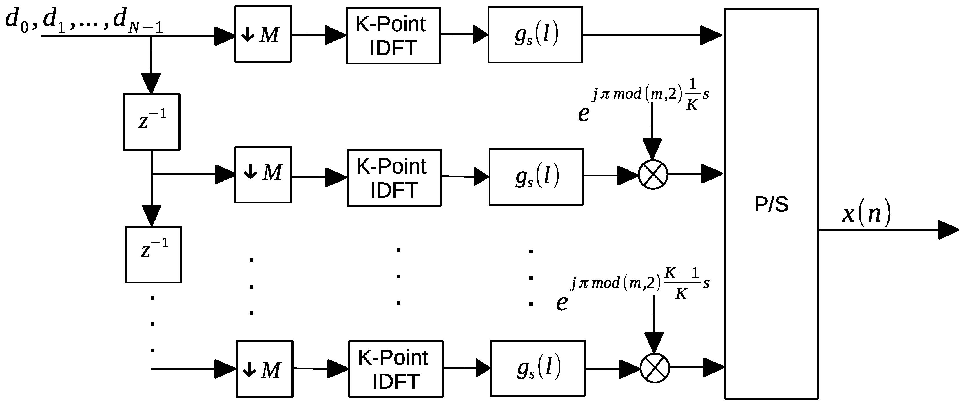
x s ( l ) = m = 0 M 1 D ( m ) g s ( l m ) e j π mod ( m , 2 ) s K
where the operations on x s ( l ) and g s ( l m ) are the same as serial-to-parallel operation with K parallel streams. Finally, the transmitted signal with convolution operation is followed:
x s ( l ) = D ( m ) × g s ( l ) e j 2 π 1 2 mod ( m , 2 ) 1 K s .
The transmitter block diagram of the hexagonal GFDM that involves Fourier transforms and the polyphase filters is given in Figure 2. Accordingly, the convolution of the symbols on frequency resources is done with the polyphase components of the filter with the phase-shifting dependent on the time slot indices. Here, the shifted version of the transmitted symbol d N is upsampled with M. Thus, the symbols are shared among K subcarriers. In each subsymbol block, the IDFT transformations and filtering operations are done, respectively. In addition, the filtering operations have fewer multiplications because of using polyphase components.
The received signal at the mth subsymbol is given as:
d ^ ( k , m ) = k = 0 K 1 l x ( l ) g ( m K l ) e j 2 π k + 1 2 mod ( m , 2 ) 1 K l .
Substitute the variable with l = a K + b
d ^ ( k , m ) = k = 0 K 1 l x ( a K + b ) g ( m K a K b ) e j 2 π k K b × e j π mod ( m , 2 ) 1 K b
and re-arrange with DFT transformation to obtain
d ^ ( k , m ) = D F T l x ( a K + b ) g ( m K a K b ) e j π mod ( m , 2 ) 1 K b .
To write the equation in a simply way with polyphase structure, change the variables again with α = m K b K and β = ( m K b ) mod ( K ) . The transmitted signal becomes as:
d ^ ( k , m ) = D F T l x ( a K + b ) g ( ( α a ) K + β ) e j π mod ( m , 2 ) 1 K b .
Write with polyphase components:
d ^ ( k , m ) = D F T l x b ( a ) g β ( α a ) e j π mod ( m , 2 ) 1 K b ,
and we know that l = a K + b where b = 0 , 1 , K 1 and a = in general terms. Thus, we can write “a” instead of “l” on summation operation. Thus, replacing with convolution, the estimated signal at receiver is obtained:
d ^ ( k , m ) = D F T x b ( a ) × g β ( a ) e j π mod ( m , 2 ) 1 K b .
The proposed receiver model of the hexagonal GFDM is given in Figure 3. Again, we utilize to IDFT/DFT transformations by using polyphase decomposition to implement the transceiver. Here, the received signal is split to the M subsymbols. Then, the filtering and DFT transformations are done, respectively.

4. Performance Evaluation

We aim to utilize the advantages of the hexagonal time-frequency lattice structure to decrease the symbol duration in communication systems with short-bursts, e.g., IoT devices. In the proposed hexagonal multicarrier scheme, we apply the polyphase decomposition to reduce computational complexity. Thus, the proposed method can support less symbol duration with fewer calculation processes. In the following subsections, the computational complexity and latency analysis of the proposed hexagonal waveform in Figure 2 are given.

4.1. Complexity Analysis

Computational complexity is concerned with the power consumption of an algorithm performs. We calculate computational complexity as an arithmetic complexity by using the numerical number of the multiplications. Polyphase decomposition is similar to parallel computing consist of splitting computation on each polyphase component which works simultaneously. Thus, the numerical number of the multiplications in each polyphase is reduced by 1 / K ratio.
We perform IDFT/DFT transformations with the using the polyphase decomposition of the prototype filter to simplify the transceiver structure. According to proposed method, the summary of the transmitter implementation is given in the following steps:
(i)
M times of K-point IDFT transformations for
(ii)
K × M times multiplication with L / K length of the filter
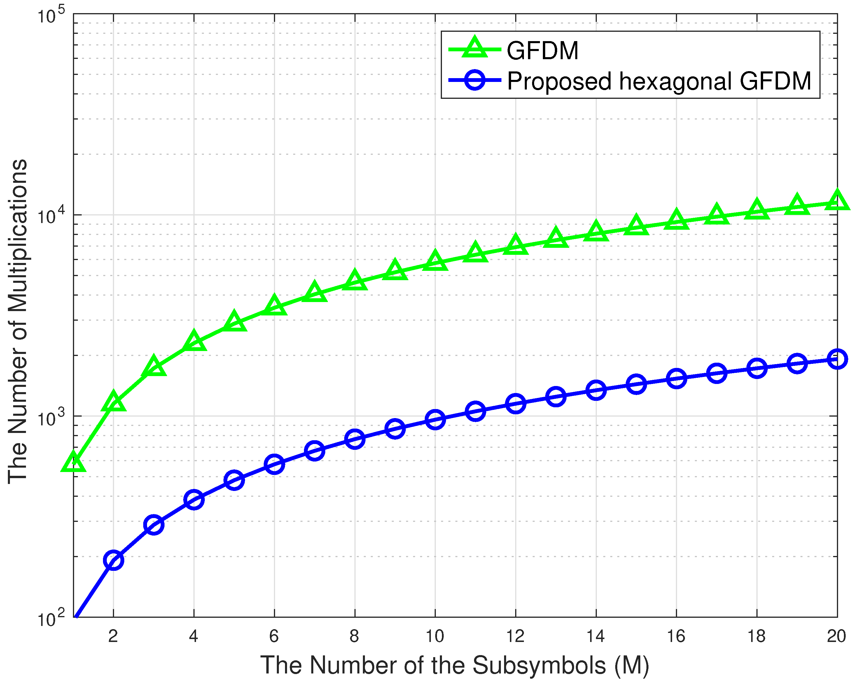
It is assumed that the K point IDFT and DFT transformation is implemented by the IFFT or FFT algorithms requiring K log 2 K multiplications. Accordingly, the operation on (7) requires K log 2 K number of multiplications for the each subsymbol. Additionally, K M times L / K number of the polyphase filter coefficients (i.e., L: filter length). The analysis of the computational complexity is introduced in Table 1. A comparison of the proposed hexagonal GFDM and traditional GFDM, according to the computational complexity, is given in Figure 4. Accordingly, the complexity is reduced with the using polyphase decomposition. Compared to the traditional GFDM, the difference in the number of multiplications is derived from parallel processing. The computational complexity load is shared among the subcarriers. Thus, the practical application of polyphase filters is to use K filters with L / K taps.

4.2. Transmission Time Analysis

The Euclidean distance between two symbols on hexagonal time-frequency lattice is less than on the rectangular lattice structure. Thus, the same number of symbols can be transmitted with a shorter transmission time compared to the rectangular lattice. For this, the Euclidean distance between symbols has to be taken into account to handle the interference between symbols. Bite error rates based on time-frequency lattice allocation are studied very well in [27,28]. Accordingly, based on the distance between symbols, transmission time decreases by about 13%. On the other hand, more symbols can be transmitted in the same transmission time. According to LTE standards, the transmitted signal is designed into subframes of 1 ms duration. Each frame consists of 14 or 12 OFDM symbols that depend on whether standard or extended cyclic prefix is used [29]. On the other hand, if frame structures are adopted to hexagonal allocation, frame duration decreases. The comparison of the optimum frame duration time of rectangular and hexagonal lattice structure based on the LTE frame structure is given in Table 2.

4.3. BER Performances of the Proposed Hexagonal GFDM

In this section, the proposed hexagonal GFDM model is evaluated in terms of the BER values on different SNR regions. A single antenna for the receiver and a single antenna for the transmitter is used for the implementation. QPSK modulated symbols are used for each subsymbol and subcarrier grid.
We implement the proposed hexagonal GFDM model in Figure 5 and Figure 6 for 16 subcarriers, K, and 6 subsymbols, M. The bit error rate (BER) performances of the proposed waveform are compared over additive white Gaussian noise (AWGN) and Rayleigh Fading channel. We consider that the Rayleigh channel is modeled as a simple flat fading. The effects of frequency selectivity on performances of the traditional GFDM and hexagonal GFDM schemes are eliminated with the complex impulse response. Moreover, we state that the effects of the proposed model on error performance more explicitly. The proper channel estimation and equalization algorithms can also be considered for the other type of channel models [24,30]. The channel adds zero mean AWGN noise with variance σ 2 , i.e., N ( 0 , σ n 2 ) . Consequently, the simulated BER results are in satisfactory limits under the theoretical BER results and GFDM performances [31]. The performance results are close to each other; the performance gains are approximately the same. Both traditional GFDM and hexagonal GFDM can be used in these conditions interchangeably depending on the requirements of the users.

5. Conclusions

In this paper, the hexagonal time-frequency allocation advantages are adopted to the GFDM scheme using polyphase decomposition. Thus, we update the GFDM model with hexagonal time-frequency lattice allocation to allow shorter transmission time. (i) The user symbols are transmitted with a prototype filter which is shifted in time and frequency. The hexagonal structure is created by shifting the symbols in the frequency domain at even subsymbols. (ii) The polyphase decomposition of the Gaussian filter is used as a prototype filter for each symbol. (iii) It allows decreasing the number of multiplications. Thus, the computational complexity is reduced compared to the traditional GFDM structure. As part of future work, using the hexagonal time-frequency lattice structures in the next-generation communication systems and evaluating according to new users’ requirements on the heterogeneous networks will be investigated. The comparison with other state-of-the-art of hexagonal multicarrier techniques and the robustness of the proposed hexagonal GFDM model on doubly dispersive channel effects will be implemented with improvements on the receiver structures.

Author Contributions

Conceptualization, methodology, implementation, validation and original draft preparation, E.C.; and manuscript review and editing, E.C., A.M. and. M.D. All authors have read and agreed to the published version of the manuscript.

Funding

This research received no external funding.

Conflicts of Interest

The authors declare no conflict of interest.

References

  1. Wunder, G.; Jung, P.; Kasparick, M.; Wild, T.; Schaich, F.; Chen, Y.; Brink, S.T.; Gaspar, I.; Michailow, N.; Festag, A.; et al. 5GNOW: Non-orthogonal, asynchronous waveforms for future mobile applications. IEEE Commun. Mag. 2014, 52, 97–105. [Google Scholar] [CrossRef]
  2. Andrews, J.G.; Buzzi, S.; Choi, W.; Hanly, S.V.; Lozano, A.; Soong, A.C.; Zhang, J.C. What will 5G be? IEEE J. Sel. Areas Commun. 2014, 32, 1065–1082. [Google Scholar] [CrossRef]
  3. Akyildiz, I.F.; Gutierrez-Estevez, D.M.; Balakrishnan, R.; Chavarria-Reyes, E. LTE-Advanced and the evolution to Beyond 4G (B4G) systems. Phys. Commun. 2014, 10, 31–60. [Google Scholar] [CrossRef]
  4. Çatak, E.; Tekçe, F.; Dizdar, O.; Durak-Ata, L. Multi-user shared access in massive machine-type communication systems via superimposed waveforms. Phys. Commun. 2019, 37, 100896. [Google Scholar] [CrossRef]
  5. Shariatmadari, H.; Ratasuk, R.; Iraji, S.; Laya, A.; Taleb, T.; Jäntti, R.; Ghosh, A. Machine-type communications: Current status and future perspectives toward 5G systems. IEEE Commun. Mag. 2015, 53, 10–17. [Google Scholar] [CrossRef] [Green Version]
  6. Palattella, M.R.; Dohler, M.; Grieco, A.; Rizzo, G.; Torsner, J.; Engel, T.; Ladid, L. Internet of Things in the 5G Era: Enablers, Architecture, and Business Models. IEEE J. Sel. Areas Commun. 2016, 34, 510–527. [Google Scholar] [CrossRef] [Green Version]
  7. Farhang-Boroujeny, B. Filter bank multicarrier modulation: A waveform candidate for 5G and beyond. Adv. Electr. Eng. 2014, 2014, 25. [Google Scholar] [CrossRef] [Green Version]
  8. Çatak, E.; Durak-Ata, L. Adaptive filterbank-based multi-carrier waveform design for flexible data rates. Comput. Electr. Eng. 2017, 61, 184–194. [Google Scholar] [CrossRef]
  9. Khelouani, I.; Elbahhar, F.; Elassali, R.; Idboufker, N. Performance Analysis of LDS Multi Access Technique and New 5G Waveforms for V2X Communication. Electronics 2020, 9, 1094. [Google Scholar] [CrossRef]
  10. Vakilian, V.; Wild, T.; Schaich, F.; ten Brink, S.; Frigon, J.F. Universal-filtered multi-carrier technique for wireless systems beyond LTE. In Proceedings of the 2013 IEEE Globecom Workshops (GC Wkshps), Atlanta, GA, USA, 9–13 December 2013; pp. 223–228. [Google Scholar] [CrossRef]
  11. Schaich, F.; Wild, T. Waveform contenders for 5G-OFDM vs. FBMC vs. UFMC. In Proceedings of the IEEE International Symposium on Communications, Control and Signal Processing (ISCCSP), Athens, Greece, 21–23 May 2014; pp. 457–460. [Google Scholar]
  12. Matthé, M.; Mendes, L.L.; Fettweis, G. Asynchronous multi-user uplink transmission with generalized frequency division multiplexing. In Proceedings of the 2015 IEEE International Conference on Communication Workshop (ICCW), London, UK, 8–12 June 2015; pp. 2269–2275. [Google Scholar]
  13. Jiang, L.; Zhang, H.; Cheng, S.; Lv, H.; Li, P. An Overview of FIR Filter Design in Future Multicarrier Communication Systems. Electronics 2020, 9, 599. [Google Scholar] [CrossRef] [Green Version]
  14. Han, F.; Zhang, X. Hexagonal Multicarrier Modulation: A Robust Transmission Scheme for Time-Frequency Dispersive Channels. IEEE Trans. Signal Process. 2007, 55, 1955–1961. [Google Scholar] [CrossRef]
  15. Xu, K.; Xu, Y.; Ma, W.; Xie, W.; Zhang, D. Time and Frequency Synchronization for Multicarrier Transmission on Hexagonal Time-Frequency Lattice. IEEE Trans. Signal Process. 2013, 61, 6204–6219. [Google Scholar] [CrossRef] [Green Version]
  16. Strohmer, T.; Beaver, S. Optimal OFDM system design through optimal sphere coverings. In Proceedings of the 2001 IEEE International Conference on Acoustics, Speech, and Signal Processing, Salt Lake City, UT, USA, 7–11 May 2001; Volume 4, pp. 2373–2376. [Google Scholar] [CrossRef] [Green Version]
  17. Ayadi, R.; Kammoun, I.; Siala, M. Efficient Offline Waveform Design Using Quincunx/Hexagonal Time-Frequency Lattices. Wireless Commun. Mob. Comput. 2017, 2017, 9207108. [Google Scholar] [CrossRef] [Green Version]
  18. Korevaar, C.W.; Kokkeler, A.B.J.; Boer, P.; Smit, G.J.M. Spectrum Efficient, Localized, Orthogonal Waveforms: Closing the Gap With the Balian-Low Theorem. IEEE Trans. Commun. 2016, 64, 2155–2165. [Google Scholar] [CrossRef]
  19. Senay, S.; Durak, L.; Chaparro, L.F. A time-frequency division multiplexing communications system with hexagonal lattice structure. In Proceedings of the 2009 17th European Signal Processing Conference, Glasgow, UK, 24–28 August 2009; pp. 1186–1189. [Google Scholar]
  20. Han, F.; Zhang, X. Asymptotic Equivalence of Two Multicarrier Transmission Schemes in Terms of Robustness Against Time—Frequency Dispersive Channels. IEEE Trans. Veh. Technol. 2010, 59, 682–691. [Google Scholar]
  21. Çatak, E.; Durak-Ata, L. An efficient transceiver design for superimposed waveforms with orthogonal polynomials. In Proceedings of the 2017 IEEE International Black Sea Conference on Communications and Networking (BlackSeaCom), Istanbul, Turkey, 5–8 June 2017; pp. 1–5. [Google Scholar]
  22. Cherubini, G.; Eleftheriou, E.; Olcer, S. Filtered multitone modulation for very high-speed digital subscriber lines. IEEE J. Sel. Areas Commun. 2002, 20, 1016–1028. [Google Scholar] [CrossRef]
  23. Michailow, N.; Gaspar, I.; Krone, S.; Lentmaier, M.; Fettweis, G. Generalized frequency division multiplexing: Analysis of an alternative multi-carrier technique for next generation cellular systems. In Proceedings of the 2012 International Symposium on Wireless Communication Systems (ISWCS), Paris, France, 28–31 August 2012; pp. 171–175. [Google Scholar] [CrossRef] [Green Version]
  24. Farhang, A.; Marchetti, N.; Doyle, L.E. Low-Complexity Modem Design for GFDM. IEEE Trans. Signal Process. 2016, 64, 1507–1518. [Google Scholar] [CrossRef] [Green Version]
  25. Alves, B.M.; Mendes, L.L.; Guimarães, D.A.; Gaspar, I. Performance of GFDM over frequency selective channels. In Proceedings of the 2013 INATEL International Workshop on Telecommunications (IWT), Minas Gerais, Brazil, 6–9 May 2013; pp. 1–6. [Google Scholar]
  26. Harris, F.; Chen, X.; Venosa, E. Chapter 6—Filter Banks for Software-Defined Radio. In Orthogonal Waveforms and Filter Banks for Future Communication Systems; Renfors, M., Mestre, X., Kofidis, E., Bader, F., Eds.; Academic Press: Cambridge, MA, USA, 2017; pp. 105–127. [Google Scholar] [CrossRef]
  27. Xu, K.; Zhu, L.; Zhang, D.; Xu, Y.; Ma, W.; Xie, W. Synchronization approach for dynamic hexagonal time–frequency lattice MCM system. Digit. Signal Process. 2014, 25, 72–83. [Google Scholar] [CrossRef]
  28. Peng, S.; Liu, A.; Pan, X.; Wang, H. Hexagonal Multicarrier Faster-Than-Nyquist Signaling. IEEE Access 2017, 5, 3332–3339. [Google Scholar] [CrossRef]
  29. Astely, D.; Dahlman, E.; Furuskär, A.; Jading, Y.; Lindström, M.; Parkvall, S. LTE: The evolution of mobile broadband. IEEE Commun. Mag. 2009, 47, 44–51. [Google Scholar] [CrossRef]
  30. Gaspar, I.; Michailow, N.; Navarro, A.; Ohlmer, E.; Krone, S.; Fettweis, G. Low Complexity GFDM Receiver Based on Sparse Frequency Domain Processing. In Proceedings of the 2013 IEEE 77th Vehicular Technology Conference (VTC Spring), Dresden, Germany, 2–5 June 2013; pp. 1–6. [Google Scholar] [CrossRef]
  31. Michailow, N.; Matthé, M.; Gaspar, I.S.; Caldevilla, A.N.; Mendes, L.L.; Festag, A.; Fettweis, G. Generalized Frequency Division Multiplexing for 5th Generation Cellular Networks. IEEE Trans. Commun. 2014, 62, 3045–3061. [Google Scholar] [CrossRef]
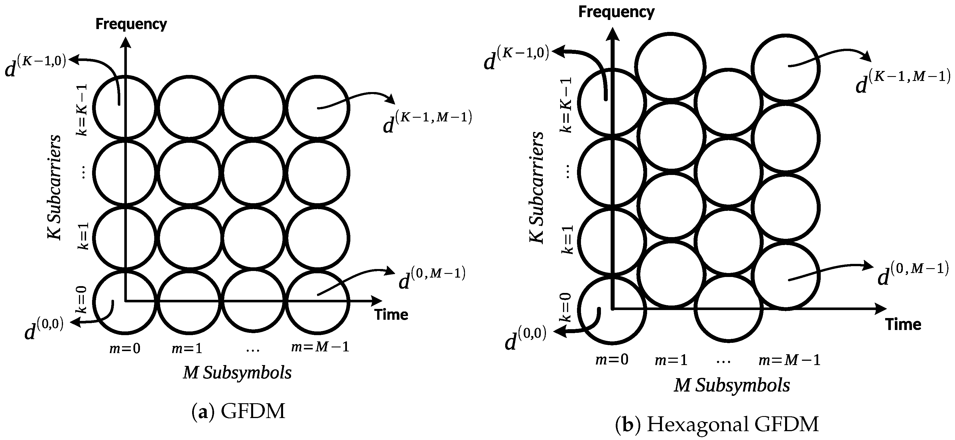
Figure 1. The time-frequency allocations of the GFDM (generalized frequency division multiplexing) model and proposed hexagonal GFDM.
Electronics 09 01862 g001
Figure 2. The transmitter part of the hexagonal multi carrier lattice structures.
Electronics 09 01862 g002
Figure 3. The receiver part of the hexagonal multi carrier lattice structures.
Electronics 09 01862 g003
Figure 4. Comparison of the proposed hexagonal GFDM and traditional GFDM model for K = 16. The proposed method has less computational complexity.
Electronics 09 01862 g004
Figure 5. The BER (bit error rate) performance of hexagonal GFDM model on AWGN channel: The simulated and theoretical results of the proposed method are similar.
Electronics 09 01862 g005
Figure 6. The BER performance of hexagonal GFDM model on the Rayleigh channel.
Electronics 09 01862 g006
Table 1. The analysis of the computational complexity of the transmitter according to the number of multiplications.
ModelThe Number of Multiplications
GFDM [23,24] M K L + M K log 2 K
Proposed Hexagonal GFDM M L + M K log 2 K
Table 2. Comparison of optimum frame duration of rectangular and hexagonal lattice structure based on the LTE frame structure.
Time-Frequency AllocationFrame DurationThe Number of the Symbols for 1 ms
Rectangular allocation on LTE standard [29]1 ms14 or 12 symbols
Hexagonal allocation 0.8 ms16 or 14 symbols
Publisher’s Note: MDPI stays neutral with regard to jurisdictional claims in published maps and institutional affiliations.