Article

On the Design and Analysis of Compact Super-Wideband Quad Element Chiral MIMO Array for High Data Rate Applications

by
Ananda Venkatesan Boologam
,
Kalimuthu Krishnan
,
Sandeep Kumar Palaniswamy
*,
C. T. Manimegalai
and
Sabitha Gauni
Department of ECE, SRM Institute of Science and Technology, Kattankulathur 603203, India
*
Author to whom correspondence should be addressed.
Electronics 2020, 9(12), 1995; https://doi.org/10.3390/electronics9121995
Submission received: 2 November 2020 / Revised: 19 November 2020 / Accepted: 21 November 2020 / Published: 25 November 2020
(This article belongs to the Special Issue Ultra-Wideband Microwave/MM-Wave Components and Packaging)

Abstract

:
This paper presents a compact, bouquet-inspired, four-element MIMO array for super wideband (SWB) applications. The proposed unit element monopole antenna has compact geometry, and it is deployed by the fusion of an elliptical and circular-shaped radiator. The convoluted geometry and semi-elliptical ground plane, along with the narrow rectangular slit defected ground structure, provides a wide impedance bandwidth. The designed unit cell has the dimensions of 32 mm × 20 mm × 0.8 mm, operates from 2.9 to 30 GHz (S11 ≤ −10 dB) and provides a bandwidth dimension ratio (BDR) of 2894. The proposed low-profile diversity array without any decoupling structures consists of four orthogonally placed, uncorrelated antennas with an inter element spacing of 0.05 λ0, occupies an area of 57 mm × 57 mm and provides dual polarization. The performance metrics of the diversity array were validated for frequencies over ultra-wideband, using mutual coupling characteristics, envelope correlation coefficient (ECC) by far-field radiation, diversity gain (DG), total active reflection coefficient (TARC), channel capacity loss (CCL) and cumulative distribution function (CDF) analysis. The measured mutual coupling over the operating band was less than −18 dB, the ECC was less than 0.004 and the TARC was less than −15 dB, and a better CCL of ˂0.28 bits/s/Hz was achieved by the fabricated antenna.

1. Introduction

Planar monopole antennas provide many advantages, from the low profile to a cost-effective prototype, depending upon the choice of substrate, as well as a wide bandwidth and nearly omnidirectional radiation characteristics. Most of the reported monopole antennas have usual layouts, such as squares, circles and ellipses, and achieve an impedance bandwidth ratio of 4:1 to 11:1 [1]. As indicated in [2,3], existing ultra-wideband (UWB) antennas can provide an impedance ratio bandwidth of 3.4:1 (3.1 to 10.6 GHz, Federal Communications Commission (FCC) standards). Due to its limited ratio bandwidth, it can support only a restricted number of wireless systems. This limitation can be avoided by deploying super wideband (SWB) antennas, which offer a minimum of a 10:1 ratio bandwidth. SWB antennas have wide coverage bandwidths which cover both short- and long-range communications. The reported compact monopole antenna [4] for SWB applications operates from 1.44 GHz to 18.8 GHz with an impedance bandwidth ratio of 1:13.06, and the physical dimensions of the antenna are 35 mm × 77 mm. The impedance matching of a proposed [5] elliptical monopole is not matched well at lower frequencies (3.0–3.8 GHz). Good impedance matching can be achieved by tapering the feed line [6], a coplanar waveguide-fed antenna [7], ground plane shaping [8], adjusting the gap between the ground plane and the radiator [9], the beveling technique [10], providing a slit in the ground plane at the backside of the feed [11] or using a semi-elliptical notched ground plane [12].
SWB antennas find applications in data communication and distribution services (12.3–12.7 GHz), personal communication systems and digital data cellular systems, depending upon the starting frequency and a bandwidth ratio of 10:1 [13]. SWB antennas may cover all services, like Bluetooth (2.45 GHz), WiMax (3.5 and 5.8 GHz) [14], WiFi (5 GHz), the UWB spectrum (3.1–10.6 GHz), C-band (4–8 GHz), 5G (sub-6 GHz band) [15] and Ku-band (12–18 GHz) applications [16].
The MIMO technique provides better diversity gain to enhance the data handling ability and interconnection network quality for various wireless communication systems. The effect of deep fading can be reduced by selecting signals in all directions [17]. In the case of diversity of antenna design, at least one of the antennas in the MIMO set needs to receive the signal in an efficient way. A UWB diversity antenna overcomes the multipath signal degradation issue in UWB wireless communication systems, and the size of the MIMO diversity antenna should be small enough to implement in handheld devices. Therefore, it is necessary to design a UWB MIMO diversity antenna with high isolation between the antenna elements for compact, portable and UWB applications [18].
However, placing multiple antennas in a limited area will worsen the mutual coupling characteristics and deteriorate the performance of a MIMO diversity antenna. While designing a MIMO diversity antenna, additional care must be taken to maintain low mutual coupling between the antenna elements without any additional circuitry [19]. The lower mutual coupling between the elements ensures high radiation efficiency and, therefore, the diversity performance of the antenna is improved [20]. There are various techniques implemented to improve the high level of isolation between the antennas, such as a slit in the ground plane [21,22], adjusting the spacing between the antenna elements [23], a stub in the ground plane [24,25], using a decoupling structure in the ground plane [26], inserting a stub between the radiators [27], the orthogonal placement of radiators [28,29,30,31,32,33] and the neutralization line technique [34,35]. Most of the existing wideband antennas are not suitable for compact diversity systems due their large sizes [36,37] and improper mutual coupling characteristics over the entire operational validated frequencies.
The introduction of a slot or slit in the ground plane widens the lower frequency of operation and also increases the isolation, but slightly affects the radiation properties [38]. Extending the stub on the ground plane or inserting the stub between the radiating elements improves the isolation characteristics at the cost of small disturbances in impedance matching [39,40]. Deployment of a decoupling structure in the MIMO antenna reduces mutual coupling by eliminating the surface wave between the antennas [41]. The usage of a decoupling structure makes the MIMO configuration more complex. Isolation can be improved significantly by using the neutralization line technique. By choosing the proper length of the line coupling, the current is reduced, but there is no standard procedure for fixing the position of the line [42].
From the above observations, it is clear that some variations are produced in the antenna parameters whenever any kind of decoupling structures are introduced for isolation improvement. In this work, an SWB monopole diversity array is presented. The radiator of the SWB monopole antenna was designed by convoluting ellipses at certain angles with circles. The convoluted radiator (bouquet-inspired), along with a modified semi-elliptical ground plane and a rectangular defected ground structure, provide a wide impedance of |S11| < 10 dB and a bandwidth of 2.9–30 GHz. The diversity antenna was constructed using four elements placed in an orthogonal manner, covering both polarization (horizontal and vertical) and pattern diversity. Chirality in the diversity architecture was due to the unequal length and width of the unit cell, and the radiator was tilted at an angle of two degrees to achieve better isolation between the antenna elements.
In Table 1, the proposed antenna is compared with other antennas (related work), and the designed four-element MIMO antenna offered better performance in terms of physical dimensions (mm2), electrical dimensions (λL × λw), bandwidth (in GHz and as a percentage), isolation, envelope correlation coefficient (ECC), diversity gain (DG) and bandwidth dimension ratio (BDR). For calculating the electrical dimensions in terms of λ, the lower frequency of operation was taken.
From the aforementioned table, the salient features of the proposed work are highlighted and are listed below.
(1)
The designed MIMO antenna operates from 2.9 to more than 30 GHz, which corresponds to a bandwidth greater than 27 GHz;
(2)
The bandwidth (GHz and %) of this proposed antenna is greater than all the other antennas referenced in Table 1;
(3)
From the standpoint of dimensions, the proposed antenna has compact geometry when compared with [20,23,27,28,30,32];
(4)
Without any decoupling structure, the isolation characteristics of the proposed MIMO antenna are better than those in [17,18,19,20,21,22,25,27,32,33];
(5)
This work also focused on the DG and ECC of the MIMO configuration. DG was not reported in [17,20,21,22,23,27,28,29,30,31], and a higher DG value is shown when compared with [24,34]. The ECC values were not reported in [21,23,27,28,30,31]. Due to the better isolation characteristics, the proposed antenna provides lower ECC compared with [17,18,19,20,22,24,25,29,32,33,34];
(6)
Due to the compact geometry and wider bandwidth, the proposed antenna offers higher a BDR value, compared with the other work referred to in the table.
This manuscript is divided into four sections. Section 1 covers the introduction and related work. Section 2 deals with unit element design and diversity array design architecture. In Section 3, results are obtained, and the radiation characteristics and diversity performance of the antenna are investigated. Section 4 concludes the research paper with highlights of the diversity antenna array.

2. Antenna Design

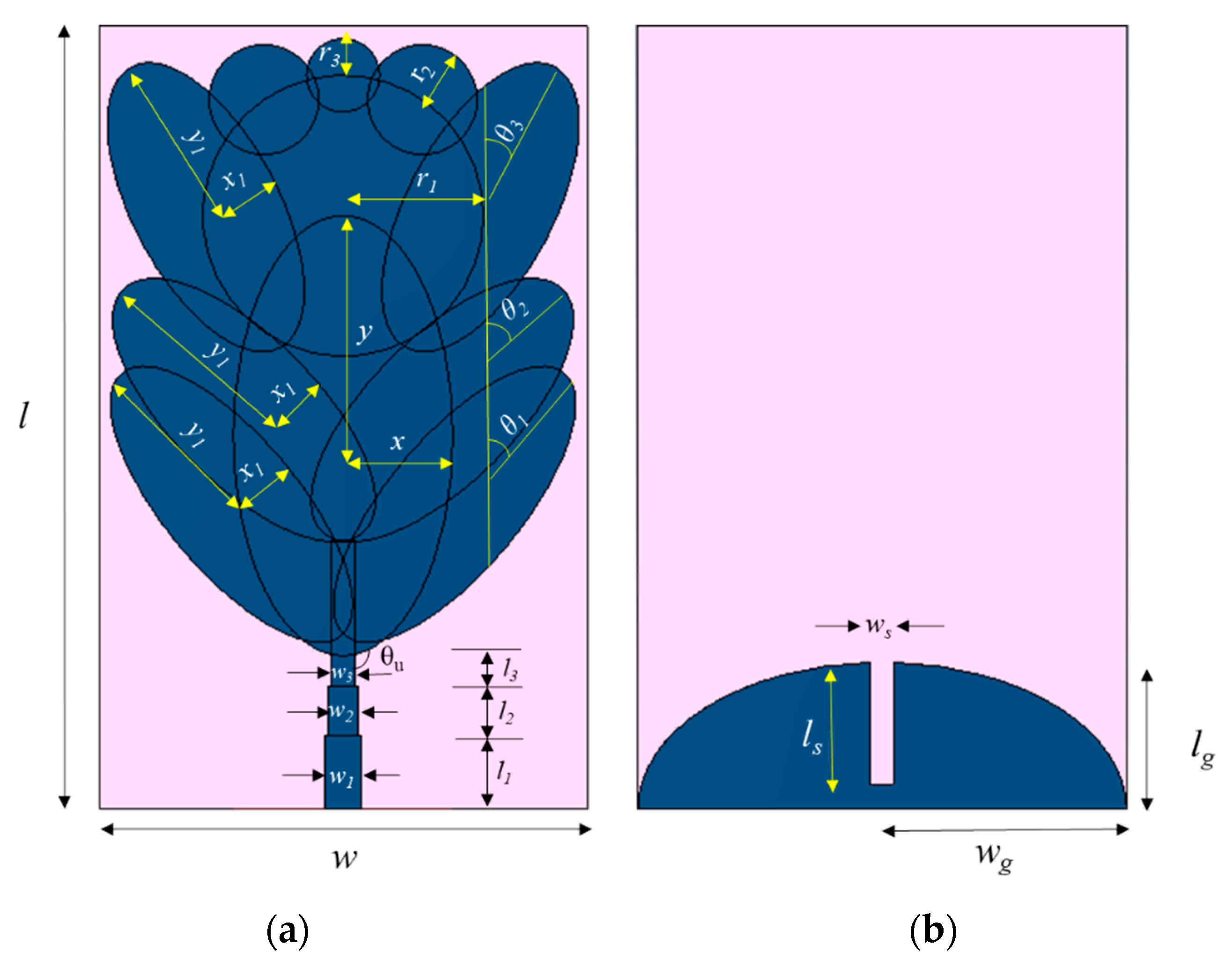
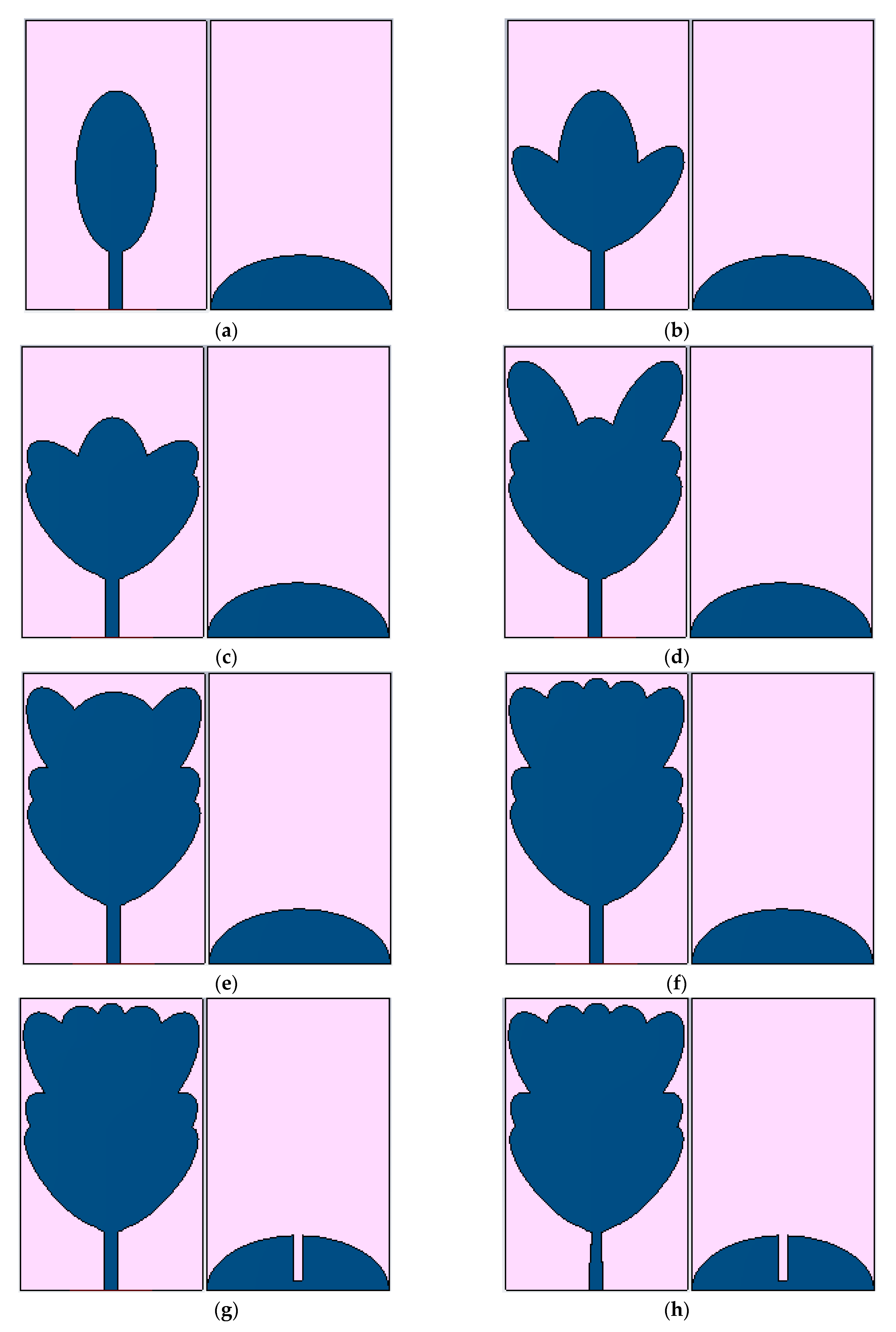
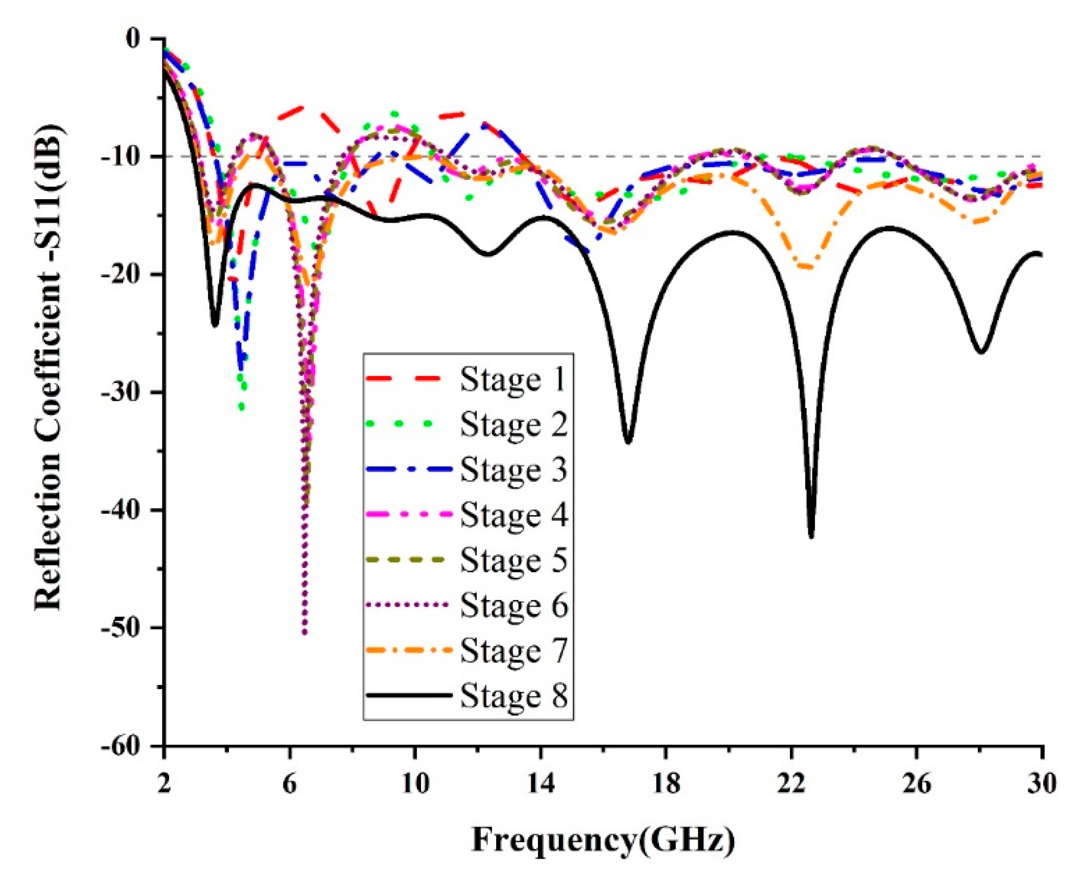
2.1. Unit Cell Design

The proposed planar monopole was designed on an FR4 substrate with a thickness 0.8 mm, relative permittivity εr = 4.3 with a loss tangent of 0.025, and radiator that was fed by a microstrip line with a thickness of 1.51 mm to match the 50 Ω impedance. Figure 1 depicts the dimension details and the unit cell layout. The proposed antenna occupied a volume of 32 mm × 20 mm × 0.8 mm.
The evolution stages of the proposed unit element are shown in Figure 2. The proposed antenna consisted of a radiator (fusion of seven ellipses and three circles) at the front, along with the tapered microstrip feed and defected semi-elliptical ground structure in the rear plane. Figure 3 depicts the reflection coefficient plots for various stages of evolution. The vertical ellipse was the fundamental structure of the radiator and is shown in Figure 2a. The basic elliptical antenna provided several resonance bands at a lower frequency and a wideband from 13.5 GHz to 30 GHz at a higher frequency, as seen in Figure 3. In order to cover the entire UWB range and beyond, the frequency was decreased by increasing the electrical path length of the antenna.
The effective length of the electrical current path was increased by fusing three pairs (bottom, middle and top) of angled ellipses on both sides of the primary vertical ellipse, as is shown in Figure 2b–d. The inclined angles of the bottom, middle and top ellipse pairs were θ1 = 30°, θ2 = 45°and θ3 = 30°, respectively. The angled ellipses provided longer current paths within the limited area itself and lower frequency shifts to 3.4 GHz, as seen in Figure 3. Further inductive loading was increased by appending a larger circle (r1 = 6 mm) to the top of the vertical ellipse, a pair of medium-sized circles (r2 = 2.25 mm) in the region between the top slanting ellipses and a smaller circle (r3 = 1.5 mm) at the top of the larger circle, which is illustrated in Figure 2e and f. Figure 3 (Stage 6) represents the further shift in the lower cut-off frequency to 3 GHz, which covered a minimum of the UWB lower cut-off frequency. Due to convolution of the ellipses and circles, inductive loading increased which, in turn, increased the Q factor of the radiator, causing a high inductive reactance given by Equation (1). However, the bandwidth was not enhanced:
Q   =   2 f L   R   =   X L R
In order to increase the bandwidth and achieve better impedance matching, a narrow rectangular slit with the dimensions ls × ws was introduced in the semi-elliptical ground plane, as is seen in Figure 2g. Due to the introduction of the slit, the capacitance effect between the radiator and the ground plane decreased, resulting in significant improvement in the impedance bandwidth. In the final stage of evolution, the microstrip feed line was tapered in two stages, as depicted in Figure 2h, to increase the flooding of the current near the radiator, thereby achieving a wide impedance bandwidth. After the final stage of evolution, the inductive reactance canceled the capacitive reactance for the entire operating band, and the antenna behaved like a purely resistive load, as expressed in Equation (2). At the final stage of evolution, better impedance matching was attained, making the antenna resonate from 2.9 GHz to 30 GHz:
Q   =   1 R L C
The simulated and measured reflection coefficient (S11) characteristic curves of the proposed unit element antenna are presented in Figure 4. With the available resources, the measurements were carried out with an Anritsu MS2037C VNA (0.5–15 GHz), and the prototype was validated for UWB and frequencies up to 15 GHz. In Figure 4, it is clearly seen that the measured reflection coefficient (S11 < −10 dB) ranged from 2.7 GHz and covered the entire UWB range, as well as higher frequencies above UWB. Compared to the simulated results, there existed some ripples and small shifts or variations in the measured results due to minute errors in fabrication, the size of the ground plane being small compared with the cables used [43,44] and a slight impedance mismatch between the connector and cable causing fraction of the current flows in the opposite direction, which produced small ripples and connector losses.
Figure 5 illustrates the measured gain and radiation efficiency of the designed SWB antenna. It was observed that gain values varied from 3.5 to 6.2 dBi, and the corresponding efficiency ranged from over 78% to 96% for the entire operating band.

2.2. MIMO Antenna Design

A four-port diversity array was proposed to ensure good reception of signals under a multipath environment. The diversity array, shown in Figure 6, consisted of four orthogonally placed unit cells separated by a distance of 5.1 mm (electrical equivalent distance of 0.05 λ0). When the unit elements were placed closely, the mutual coupling increased, and the ECC became greater. The ECC could be reduced by increasing the separation distance between the elements, but this may have led to an increase in the dimensions of the diversity antenna. It was necessary to make a compromise between the mutual coupling and separation distance between the antenna elements. In this proposed design, a better ECC < 0.004 was achieved in the limited area itself by adjusting the orientation of each unit cell’s radiator by a tilting angle of θa = 2°. This additional tilting angle improved the isolation between the elements at higher frequencies in the diversity configuration. Due to tilting of the unit cell by the extra angle θa = 2°, the required S11 response was affected and was found to not be the response of the proposed unit cell without tilting. This S11 mismatch was overcome by shifting the x center of the fundamental vertical ellipse of the tilted radiator by 0.5 mm. When the diversity array was constructed on a FR4 substrate of the size 57 mm × 57 mm with an additional tilt angle of θa = 2°, the mutual coupling characteristics were similar in the same level of the diversity array, which was designed on the same substrate of the size 60 mm × 60 mm without the additional tilting angle of the radiator.

3. Results and Discussion

In order to validate the performance characteristics of the proposed SWB monopole diversity array for UWB and 5G frequencies, a four-port MIMO antenna was fabricated, and its performance was tested using an Anritsu MS2037C vector network analyzer. The measured mutual coupling between the antennas in the array is shown in Figure 7. It can be seen that the mutual coupling among the elements was less than −18 dB for the entire operating frequency range.

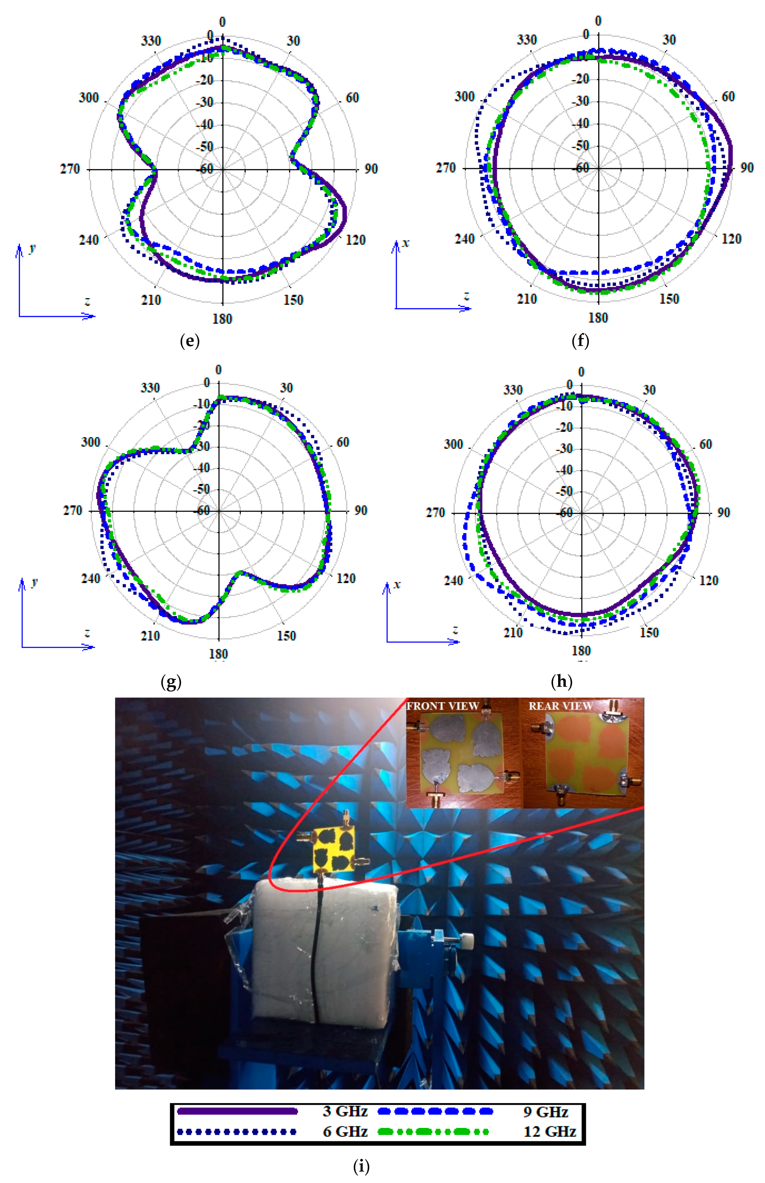
3.1. Radiation Characteristics Realization of the MIMO Antenna

Figure 8 typifies the radiation performance of the designed diversity array at various frequencies, namely 3, 6, 9 and 12 GHz. The orthogonal arrangement of the antenna elements in the diversity configuration ensured polarization and pattern diversity.
The measured E-plane and H-plane radiation pattern characteristics of the various antennas of the diversity architecture are plotted in Figure 8. It can be seen that the loss occurred by one element in one direction was equalized by a higher directive gain of other antenna in that direction. It can also be noticed from the orthogonal arrangement that at least one antenna would receive the signal in an efficient way. However, the signal underwent a multipath fading scenario, with respect to polarization. The anechoic measurement setup is also shown in Figure 8i.

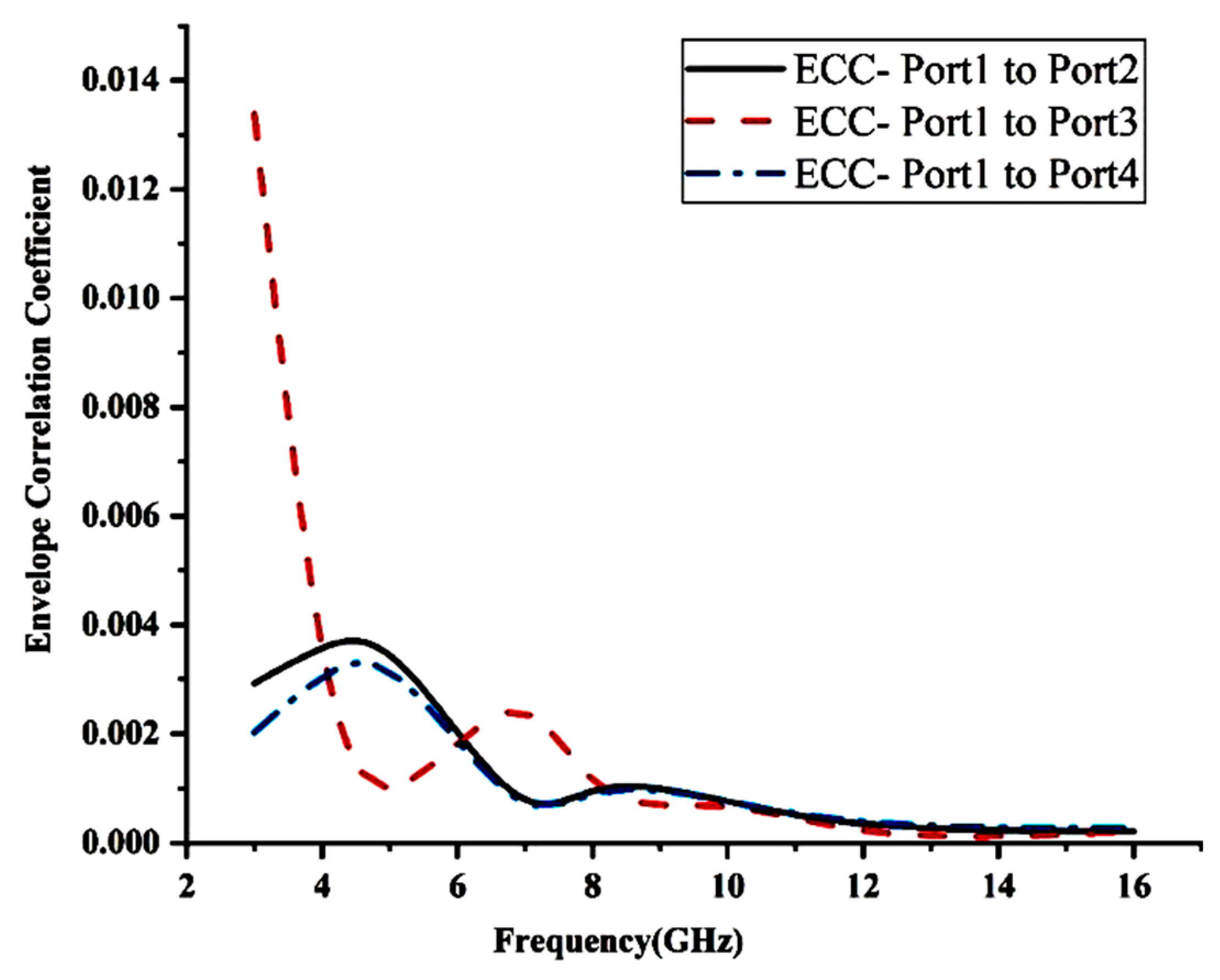
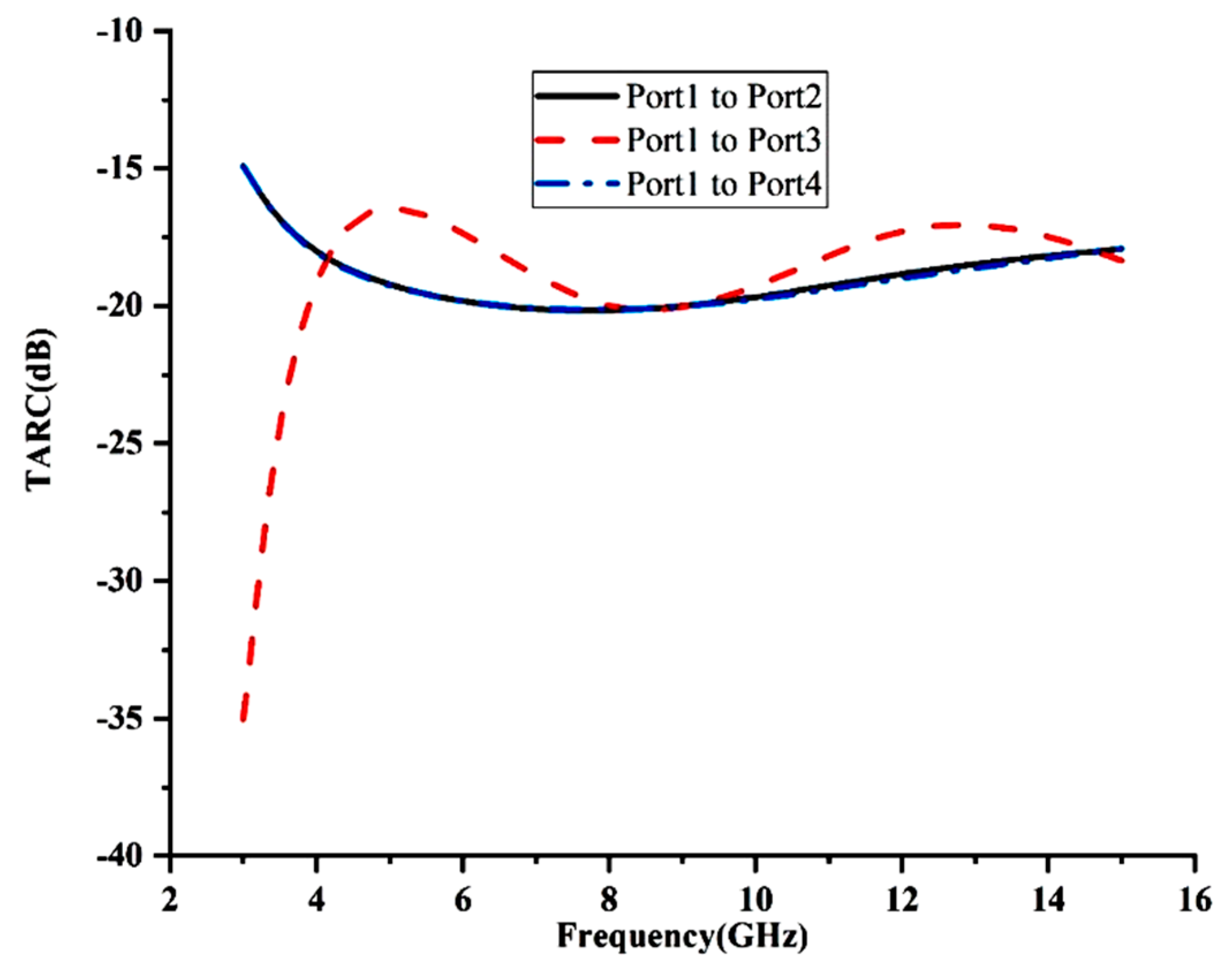
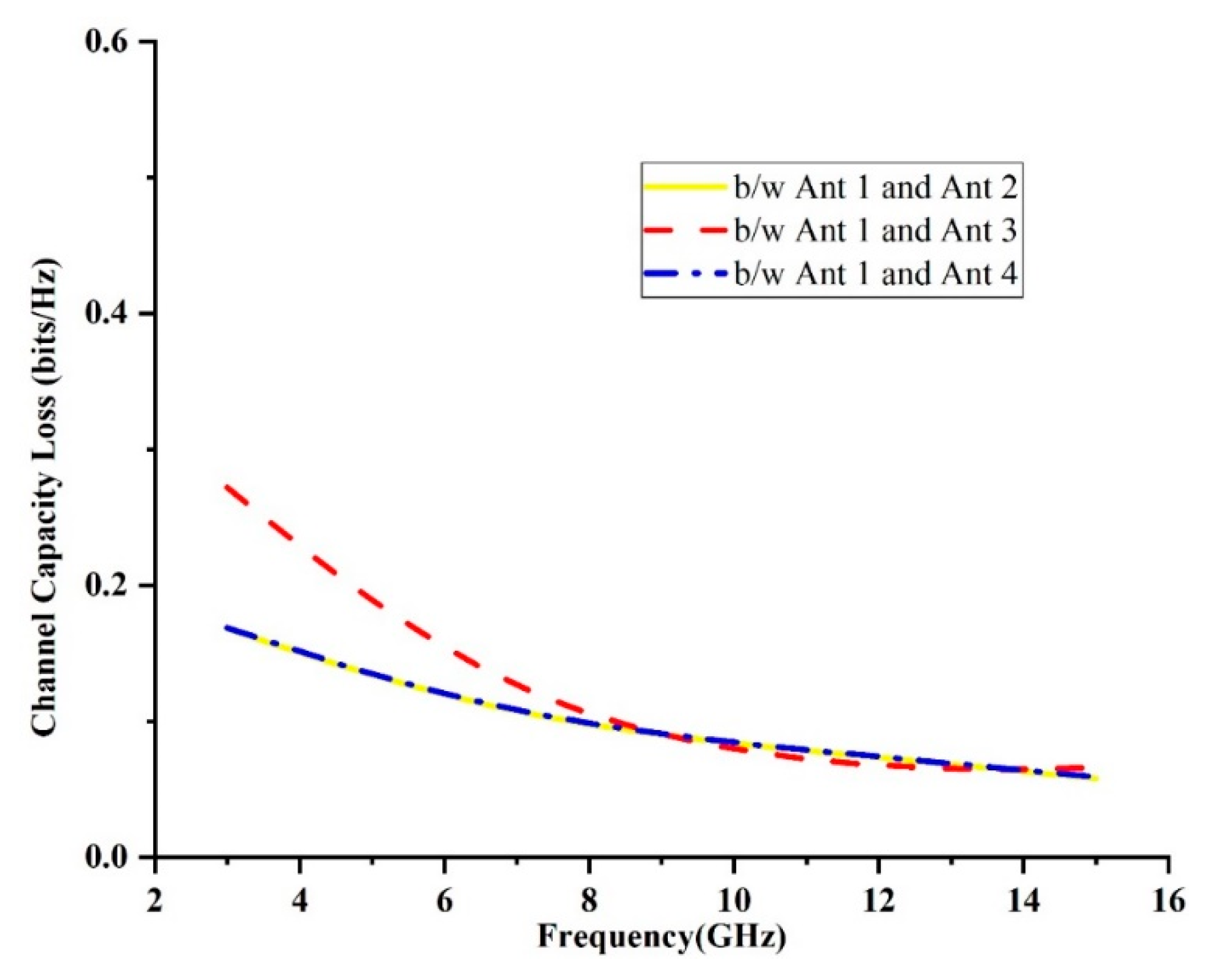
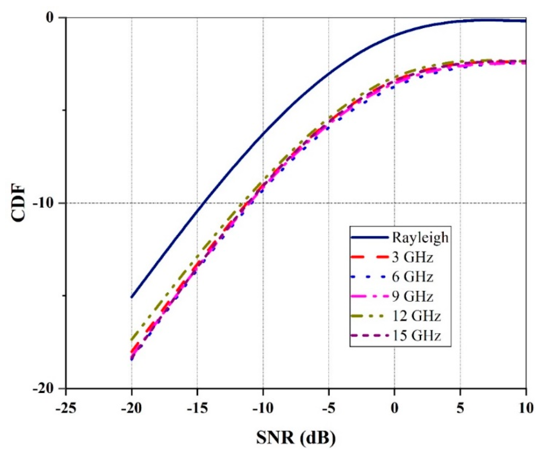
3.2. Performance Metrics of the Proposed Diversity Antenna

Single antenna element performance metrics, such as (S11 ≤ −10 dB) bandwidth, efficiency and radiation patterns, are also required for MIMO diversity antenna systems. Analyses of MIMO diversity performance metrics, such as the ECC, diversity gain, total active reflection coefficient (TARC), channel capacity loss (CCL) and cumulative distribution function (CDF), were required for effective multiantenna system design. The aforementioned metrics take into account the prime, important effect of the adjacent placement of antennas in the MIMO diversity architecture.
The performance of the proposed array under the diversity scenario was evaluated using the ECC. The ECC gave information about the amount of coupling between the antennas [45]. The envelope correlation coefficient was evaluated from the far field and is represented by Equation (3):
ρ e =   | [ F 1 ( θ , φ ) . F 2 ( θ , φ ) ] d Ω | 2 | F 1 ( θ , φ ) | 2 d Ω   | F 2 ( θ , φ ) | 2 d Ω
The measured ECC (as portrayed in Figure 9) was less than 0.004 over the entire operating band from 2.7 GHz to frequencies >15 GHz. This signified that there was much less coupling between the antenna elements in the diversity architecture proposed. Due to deployment of the diversity scheme, the increase in the signal-to-noise ratio was estimated by the diversity gain. The apparent diversity gain (Gapp), effective diversity gain (Geff) and mean effective gain (MEG) were the three additional parameters which supported the performance of the diversity array. The apparent diversity gain (Equation (4)) described the increase in the signal power level when multiple antennas were used to select the signals from different directions:
G app   =   10   ×   1 |   ρ e | 2
Geff = ηtotal × Gapp
The measured apparent diversity gain for the proposed antenna, calculated using the S-parameter for all frequencies, was greater than 9.9 dB, as depicted in Table 2. Effective diversity gain is a measure of the total antenna efficiency, including all possible losses such as ohmic loss, reflection loss and mutual coupling, represented by Equation (5).
The mean effective gain relates the power harvested by the diversity antenna to the power accepted by an omnidirectional radiator [46]. The MEG for the proposed diversity was calculated using Equation (6), and the value was almost equal to one:
MEGi   =   1     j = 1 M | S i j |
The TARC is a measure of diversity array efficiency which involves the effects of mutual coupling [38,47,48]. The TARC can be evaluated by using Equation (7):
Γ a t   =   ( | ( S 11   +   S 12 e j θ ) | 2   +   | ( S 21   +   S 22 e j θ ) | 2 ) 2
The measured TARC from the reflection coefficient was less than −15.5 dB (as shown in Figure 10), showing that the diversity array efficiency was not affected significantly due to the high isolation factor of the antennas in the diversity set.
In the proposed MIMO diversity antenna, a set high isolation or low mutual coupling (the result of adjacent placement of the antennas) between the elements was achieved by orthogonal placement of the antenna elements and by tilting the unit element by an additional angle of 2°. As a result, the diversity metrics, such as the ECC, became low and was found to be less than 0.004 over the measured frequencies of operation. Due to the orthogonal placement of unit elements in the MIMO set, polarization and pattern diversity was achieved, which in turn improved the diversity gain and, since the diversity gain depends upon the ECC, better values for all the antennas were achieved around 10 dB. Likewise, an efficient reduction in the TARC was observed.
The CCL was another important parameter in ensuring the throughput of the MIMO configuration. It provided information about the losses which occurred in the channel capacity due to correlation between the antenna elements [49,50,51]. The measured CCL values for the entire operating band are depicted in Figure 11 and were found to be less than 0.28 bits/s/Hz, which clearly shows that the designed MIMO antenna set had a better throughput:
C C L =   l o g 2 | ψ | R
In order to validate the diversity performance of the four-port MIMO antenna, the CDF was calculated by assuming Rayleigh channel conditions [52,53]. The CDF was computed for various frequencies with different Signal to Noise Ratio (SNR) values using Equation (9) and plotted in Figure 12.
P M R C   ( γ X ) = 1 i = 1 N ( λ i N 1   e X λ i i j N λ i λ j )
Λ M R C = ρ e M E G i M E G j
Along with the MIMO performance metrics, the BDR was taken into account in order to ensure the compactness of the planar antenna [54]. It gave information about how much of the electrical unit area was utilized for producing each bandwidth percentage:
BDR   =   B a n d w i d t h ( % ) ( λ Length   ×   λ Width )
The BDR values for the various antennas in the literature and for the proposed antenna were calculated using Equation (11). From the BDR comparison, as demonstrated in Table 1, it is evident that the proposed antenna had a higher BDR value, showing a high bandwidth with a small size, comparable to the lowest cut-off frequency’s wavelength and well suited for all kinds of diversity applications.
The proposed SWB monopole antenna had an extremely wide bandwidth, which was suitable for high data rate communications and, since the proposed antenna covered a bandwidth from 2.7 GHz to frequencies greater than 30 GHz, there were several bands in this frequency range and the proposed antenna that may be potential candidates which could be used for multiservice communications, such as in wireless local area network (WLAN −3.6 GHz, 4.9 GHz, 5 GHz, or 5.9 GHz), High Performance Radio LAN (HIPERLAN/2, 5 GHz region), Worldwide Interoperability for Microwave Access (WiMAX), ultra-wideband dongles, UWB short-range communications, wireless USB, 4G and 5G dongles (sub-6 GHz band), C-band, Ku-band, K-band operations, and Multichannel Video Distribution and Data Service (MVDDS) applications.

4. Conclusions

A low-profile SWB planar monopole antenna suitable for high data rate applications has been presented in this manuscript. With the aid of the monopole antenna, a compact diversity array has been designed, and its performance was analyzed in terms of its ECC, diversity gain, TARC and CCL. The proposed antenna provided better mutual coupling characteristics in the confined area without any additional decoupling structures between the elements. The additional tilting angle of the radiator ensured high isolation between the antennas of the diversity set. The SWB diversity antenna has been fabricated and validated for UWB frequencies and more. The constructed four-port diversity array architecture had better ECC values of <0.004, a high diversity gain of >9.9 dB, a low TARC of <−15 dB and a better CCL of <0.28 bits/s/Hz. The aforementioned antenna found applications where a high data rate is a prime concern in the multipath environment.

Author Contributions

Conceptualization, A.V.B., K.K., S.K.P., C.T.M. and S.G.; methodology, S.K.P.; software, A.V.B.; validation, K.K. and S.K.P.; formal analysis, A.V.B. and S.K.P.; investigation, K.K., S.K.P., C.T.M. and S.G.; resources, K.K., S.K.P., C.T.M. and S.G.; data curation, A.V.B. and S.K.P.; writing—original draft preparation, A.V.B., K.K. and S.K.P.; writing—review and editing, K.K., S.K.P., C.T.M. and S.G.; visualization, A.V.B. and S.K.P.; supervision, K.K. and S.K.P.; project administration, K.K. and S.K.P. All authors have read and agreed to the published version of the manuscript.

Funding

This research work received no external funding.

Acknowledgments

The authors acknowledge the Radio Communication and Millimeter Wave laboratory, RF and Photonics FIST laboratory, Department of ECE, SRM Institute of Science and Technology, Kattankulathur, India; CEG, Anna University, Chennai, India and Sri Sivasubramanya Nadar college of Engineering, India for providing the measurement facilities.

Conflicts of Interest

The authors declare no conflict of interest.

References

  1. Deng, C.; Xie, Y.-J.; Li, P. CPW-Fed Planar Printed Monopole Antenna with Impedance Bandwidth Enhanced. IEEE Antennas Wirel. Propag. Lett. 2009, 8, 1394–1397. [Google Scholar] [CrossRef]
  2. Manohar, M.; Kshetrimayum, R.S.; Gogoi, A.K. Super wideband antenna with single band suppression. Int. J. Microw. Wirel. Technol. 2015, 9, 143–150. [Google Scholar] [CrossRef] [Green Version]
  3. Srivastava, K.; Kumar, A.; Kanaujia, B.K.; Dwari, S.; Kumar, S. A CPW fed UWB MIMO antenna with integrated GSM band and Dual band notches. Int. J. RF Microw. Comput. Aided Eng. 2018. [Google Scholar] [CrossRef] [Green Version]
  4. Chen, K.-R.; Sim, C.-Y.-D.; Row, J.-S. A Compact Monopole Antenna for Super Wideband Applications. IEEE Antennas Wirel. Propag. Lett. 2011, 10, 488–491. [Google Scholar] [CrossRef]
  5. Manohar, M.; Kshetrimayum, R.S.; Gogoi, A.K. Printed monopole antenna with tapered feed line, feed region and patch for super wideband applications. IET Microw. Antennas Propag. 2014, 8, 39–45. [Google Scholar] [CrossRef] [Green Version]
  6. Chandel, R.; Gautam, A.K.; Rambabu, K. Tapered Fed Compact UWB MIMO-Diversity Antenna with Dual Band-Notched Characteristics. IEEE Trans. Antennas Propag. 2018, 66, 1677–1684. [Google Scholar] [CrossRef]
  7. Rahman, M.; Haider, A.; Naghshvarianjahromi, M. A Systematic Methodology for the Time-Domain Ringing Reduction in UWB Band-Notched Antennas. IEEE Antennas Wirel. Propag. Lett. 2020, 19, 482–486. [Google Scholar] [CrossRef]
  8. Srifi, M.N.; El Mrabet, O.; Falcone, F.; Ayza, M.S.; Essaaidi, M. A Novel Compact Printed Circular Antenna for Very Ultra wideband Applications. Microw. Opt. Technol. Lett. 2009, 51, 1130–1134. [Google Scholar] [CrossRef]
  9. John, M.; Ammann, M.J. Optimization of impedance bandwidth for the printed rectangular monopole antenna. Microw. Opt. Technol. Lett. 2005, 47, 153–154. [Google Scholar] [CrossRef] [Green Version]
  10. Ammann, M.J. Control of the impedance bandwidth of wideband planar monopole antennas using a beveling technique. Microw. Opt. Technol. Lett. 2001, 30, 229–232. [Google Scholar] [CrossRef]
  11. Bao, X.L.; Ammann, M.J. Investigation on UWB printed monopole antenna with rectangular slitted groundplane. Microw. Opt. Technol. Lett. 2007, 49, 1585–1587. [Google Scholar] [CrossRef]
  12. Kimouche, H.; Abed, D.; Atrouz, B.; Aksas, R. Bandwidth enhancement of rectangular monopole antenna using modified semi-elliptical ground plane and slots. Microw. Opt. Technol. Lett. 2010, 52, 54–58. [Google Scholar] [CrossRef]
  13. Kumar, S.; Lee, G.H.; Kim, D.H.; Haunan, N.S.; Choi, H.C.; Kim, K.W. Compact Planar Super-Wideband Monopole Antenna with Four Notched Bands. Electronics 2020, 9, 1204. [Google Scholar] [CrossRef]
  14. Haider, A.; Rahman, M.; Naghshvarianjahromi, M.; Kim, H.S. Time-Domain Investigation of Switchable Filter Wide-Band Antenna for Microwave Breast Imaging. Sensors 2020, 20, 4302. [Google Scholar] [CrossRef]
  15. Sarkar, D.; Srivastava, K.V. A Compact Four-Element MIMO/Diversity Antenna with Enhanced Bandwidth. IEEE Antennas Wirel. Propag. Lett. 2017, 16, 2469–2472. [Google Scholar] [CrossRef]
  16. Palaniswamy, S.K.; Kanagasabai, M.; Kumar, S.A.; Alsath, M.G.N.; Velan, S.; Pakkathillam, J.K. Super wideband printed monopole antenna for ultra wideband applications. Int. J. Microw. Wirel. Technol. 2015, 9, 133–141. [Google Scholar] [CrossRef]
  17. Liu, L.; Cheung, S.W.; Yuk, T.I. Compact MIMO Antenna for Portable Devices in UWB Applications. IEEE Trans. Antennas Propag. 2013, 61, 4257–4264. [Google Scholar] [CrossRef] [Green Version]
  18. Zhang, S.; Ying, Z.; Xiong, J.; He, S. Ultra wideband MIMO/Diversity Antennas with a Tree-Like Structure to Enhance wideband isolation. IEEE Antennas Wirel. Propag. Lett. 2009, 8, 1279–1281. [Google Scholar] [CrossRef]
  19. Mohammed, G.N.A.; Kanagasabai, M. Compact UWB Monopole Antenna for Automotive Communications. IEEE Trans. Antennas Propag. 2015, 63, 4204–4208. [Google Scholar]
  20. Jusoh, M.; Bin Jamlos, M.F.; Bin Kamarudin, M.R.; Malek, M.F.B.A. A Mimo Antenna Design Challenges for Uwb Application. Prog. Electromagn. Res. B 2012, 36, 357–371. [Google Scholar] [CrossRef] [Green Version]
  21. Li, Q.; Feresidis, A.P.; Mavridou, M.; Hall, P.S. Miniaturized Double-Layer EBG Structures for Broadband Mutual Coupling Reduction Between UWB Monopoles. IEEE Trans. Antennas Propag. 2015, 63, 1168–1171. [Google Scholar] [CrossRef]
  22. Babu, K.V.; Anuradha, B. Design of MIMO antenna to interference inherent for ultra wide band systems using defected ground structure. Microw. Opt. Technol. Lett. 2019, 61, 2698–2708. [Google Scholar] [CrossRef]
  23. Radhi, A.H.; Nilavalan, R.; Wang, Y.; Al-Raweshidy, H.S.; Eltokhy, A.A.; Ab Aziz, N. Mutual coupling reduction with a wideband planar decoupling structure for UWB–MIMO antennas. Int. J. Microw. Wirel. Technol. 2018, 10, 1143–1154. [Google Scholar] [CrossRef] [Green Version]
  24. Iqbal, A.; Saraereh, O.A.; Ahmad, A.W.; Bashir, S. Mutual Coupling Reduction Using F-Shaped Stubs in UWB-MIMO Antenna. IEEE Access 2018, 6, 2755–2759. [Google Scholar] [CrossRef]
  25. Gurjar, R.; Upadhyay, D.K.; Kanaujia, B.K.; Sharma, K. A novel compact self-similar fractal UWB MIMO antenna. Int. J. RF Microw. Comput. Eng. 2019, 29, e21632. [Google Scholar] [CrossRef]
  26. Ali, W.A.; Ibrahim, A.A. A compact double-sided MIMO antenna with an improved isolation for UWB applications. AEU—Int. J. Electron. Commun. 2017, 82, 7–13. [Google Scholar] [CrossRef]
  27. Kiem, N.K.; Phuong, H.N.B.; Chein, D.N. Design of compact 4×4 UWB-MIMO antenna with WLAN band rejection. Int. J. Antennas Propag. 2014, 2014, 1–11. [Google Scholar] [CrossRef]
  28. Lin, S.-Y.; Huang, H.-R. Ultra-wideband MIMO antenna with enhanced isolation. Microw. Opt. Technol. Lett. 2008, 51, 570–573. [Google Scholar] [CrossRef]
  29. Mathur, R.; Dwari, S. Compact CPW-Fed ultrawideband MIMO antenna using hexagonal ring monopole antenna elements. AEU—Int. J. Electron. Commun. 2018, 93, 1–6. [Google Scholar] [CrossRef]
  30. Saad, A.A.R. Approach for improving inter-element isolation of orthogonally polarised MIMO slot antenna over ultra-wide bandwidth. Electron. Lett. 2018, 54, 1062–1064. [Google Scholar] [CrossRef]
  31. Zhu, J.; Li, S.; Feng, B.; Deng, L.; Yin, S. Compact Dual-Polarized UWB Quasi-Self-Complementary MIMO/Diversity Antenna with Band-Rejection Capability. IEEE Antennas Wirel. Propag. Lett. 2016, 15, 905–908. [Google Scholar] [CrossRef]
  32. Hasan, N.; Chu, S.; Bashir, S. A DGS monopole antenna loaded with U-shape stub for UWB MIMO applications. Microw. Opt. Technol. Lett. 2019, 61, 2141–2149. [Google Scholar] [CrossRef]
  33. Singhal, S. Four element ultra-wideband fractal multiple-input multiple-output antenna. Microw. Opt. Technol. Lett. 2019, 61, 2811–2818. [Google Scholar] [CrossRef]
  34. Tiwari, R.N.; Singh, P.; Kanaujia, B.K.; Srivastava, K. Neutralization technique based two and four port high isolation MIMO antennas for UWB communication. AEU—Int. J. Electron. Commun. 2019, 110. [Google Scholar] [CrossRef]
  35. Mishra, M.; Chaudhuri, S.; Kshetrimayum, R.S.; Chel, H. Low mutual coupling six-port planar antenna for the MIMO applications. Int. J. RF Microw. Comput. Eng. 2020, 30. [Google Scholar] [CrossRef]
  36. Raheja, D.K.; Kanaujia, B.K.; Kumar, S. Low profile four-port super-wideband multiple-input-multiple-output antenna with triple band rejection characteristics. Int. J. RF Microw. Comput. Eng. 2019, 29. [Google Scholar] [CrossRef]
  37. Yadav, R.; Malviya, L. UWB antenna and MIMO antennas with bandwidth, band-notched, and isolation properties for high-speed data rate wireless communication: A review. Int. J. RF Microw. Comput. Eng. 2019, 30. [Google Scholar] [CrossRef]
  38. Chouhan, S.; Panda, D.K.; Gupta, M.; Singhal, S. Multiport MIMO antennas with mutual coupling reduction techniques for modern wireless transreceive operations: A review. Int. J. RF Microw. Comput. Eng. 2018, 28, e21189. [Google Scholar] [CrossRef]
  39. Mao, C.-X.; Chu, Q.-X. Miniaturization of UWB antenna by asymmetrically extending stub from ground. J. Electromagn. Waves Appl. 2014, 28, 531–541. [Google Scholar] [CrossRef]
  40. Kumar, R.; Pazare, N. A CPW-fed stepped slot UWB antenna for MIMO/diversity applications. Int. J. Microw. Wirel. Technol. 2015, 9, 151–162. [Google Scholar] [CrossRef]
  41. Khan, M.S.; Shoaib, I.; Autizi, E.; Capobianco, A.-D.; Najam, A.I.; Shafique, M.F. Compact ultra-wideband diversity antenna with a floating parasitic digitated decoupling structure. IET Microw. Antennas Propag. 2014, 8, 747–753. [Google Scholar] [CrossRef]
  42. Gnanaharan, I.; Anbazhagan, R. Review on the Design of the Isolation Techniques for UWB-MIMO Antennas. Adv. Electromagn. 2018, 7, 46–70. [Google Scholar] [CrossRef]
  43. Palaniswamy, S.K.; Selvam, Y.P.; Alsath, M.G.N.; Kanagasabai, M.; Kingsly, S.; Subbaraj, S. 3-D Eight-Port Ultrawideband Antenna Array for Diversity Applications. IEEE Antennas Wirel. Propag. Lett. 2016, 16, 569–572. [Google Scholar] [CrossRef]
  44. Chen, Z.N.; See, T.S.P.; Qing, X. Small Printed Ultrawideband Antenna with Reduced Ground Plane Effect. IEEE Trans. Antennas Propag. 2007, 55, 383–388. [Google Scholar] [CrossRef]
  45. Tirado-Mendez, J.A.; Gómez-Villanueva, R.; Jardón-Aguilar, H.; Fritz-Andrade, E.; Rangel-Merino, A. UWB MIMO antenna implemented with orthogonal quasi-circular slot dipole radiators. Int. J. RF Microw. Comput. Eng. 2019, 29. [Google Scholar] [CrossRef]
  46. Khan, A.A.; Jamaluddin, M.H.; Nasir, J.; Khan, R.; Aqeel, S.; Saleem, J. Owais design of a dual-band mimo dielectric resonator antenna with pattern diversity for Wimax and Wlan applications. Prog. Electromagn. Res. M 2016, 50, 65–73. [Google Scholar] [CrossRef] [Green Version]
  47. Fritz-Andrade, E.; Jardon-Aguilar, H.; Tirado-Mendez, J.A. The correct application of total active reflection coefficient to evaluate MIMO antenna systems and its generalization to N ports. Int. J. RF Microw. Comput. Eng. 2020, 30. [Google Scholar] [CrossRef]
  48. Wang, F.; Li, S.; Zhou, Q.; Gong, Y.-B. Compact Wideband Quad-Element Mimo Antenna with Reversed S-Shaped Walls. Prog. Electromagn. Res. M 2019, 78, 193–201. [Google Scholar] [CrossRef] [Green Version]
  49. Sampath, R.; Selvan, K.T. Compact hybrid Sierpinski Koch fractal UWB MIMO antenna with pattern diversity. Int. J. RF Microw. Comput. Eng. 2019. [Google Scholar] [CrossRef]
  50. Pannu, P.; Sharma, D.K. A low-profile quad-port UWB MIMO Antenna using defected ground structure with dual notch-band behaviour. Int. J. RF Microw. Comput. Aided Eng. 2020, 30, e22288. [Google Scholar] [CrossRef]
  51. Saadh, A.M.; Ashwath, K.; Ramaswamy, P.; Ali, T.; Anguera, J. A uniquely shaped MIMO antenna on FR4 material to enhance isolation and bandwidth for wireless applications. AEU—Int. J. Electron. Commun. 2020, 123, 153316. [Google Scholar] [CrossRef]
  52. Payandehjoo, K.; Abhari, R. Highly-isolated unidirectional multi-slot-antenna systems for enhanced MIMO performance. Int. J. RF Microw. Comput. Eng. 2013, 24, 289–297. [Google Scholar] [CrossRef]
  53. Alsath, M.G.N.; Arun, H.; Selvam, Y.P.; Kanagasabai, M.; Kingsly, S.; Subbaraj, S.; Sivasamy, R.; Palaniswamy, S.K.; Natarajan, R.; Alsath, M.G.N. An Integrated Tri-Band/UWB Polarization Diversity Antenna for Vehicular Networks. IEEE Trans. Veh. Technol. 2018, 67, 5613–5620. [Google Scholar] [CrossRef]
  54. Kumar, M.; Nath, V. A high BDR microstrip-line fed antenna with multiple asymmetric elliptical wide-slots for wideband applications. Int. J. RF Microw. Comput. Eng. 2020, 30. [Google Scholar] [CrossRef]
Figure 1. Proposed SWB monopole antenna. (a) Front view (radiator) and (b) rear view (ground). l = 32 mm, w = 20 mm, x = 4.5 mm, x1 = 3 mm, y = 9 mm, y1 = 7 mm, r1 = 6 mm, r2 = 2.25 mm, r3 = 1.5 mm, l1 = 3 mm, l2 = 2 mm, l3 = 2.1 mm, w1 = 1.51 mm, w2 = 1.2 mm, w3 = 1 mm, wg = 10 mm, lg = 6 mm, ls = 5 mm, ws = 1 mm, θu = 152°, θ1 = 30°, θ2 = 45° and θ3 = 30°.
Electronics 09 01995 g001
Figure 2. Evolution of the proposed SWB antenna. (a) Stage 1; (b) Stage 2; (c) Stage 3; (d) Stage 4; (e) Stage 5; (f) Stage 6; (g) Stage 7; and (h) Stage 8.
Electronics 09 01995 g002
Figure 3. Reflection coefficient (S11) characteristics of various stages, evolved in the design of the proposed SWB planar monopole antenna.
Electronics 09 01995 g003
Figure 4. Simulated and measured reflection coefficient characteristics of the proposed unit cell SWB antenna.
Electronics 09 01995 g004
Figure 5. Measured gain and efficiency of the proposed SWB antenna.
Electronics 09 01995 g005
Figure 6. Four-element diversity architecture. (a) Front view, and (b) rear view.
Electronics 09 01995 g006
Figure 7. Measured S-parameters (S11—reflection coefficient; S12, S13, S14—mutual coupling) characteristics of the proposed diversity array.
Electronics 09 01995 g007
Figure 8. Measured radiation pattern of the proposed diversity array. (a) Ant1 E-field pattern, φ = 90°; (b) Ant1 H-field pattern, φ = 0°; (c) Ant2 E-field pattern, φ = 90°; (d) Ant2 H-field, φ = 0°; (e) Ant3 E-field pattern, φ = 90°; (f) Ant3 H-field pattern, φ = 0°; (g) Ant4 E-field pattern, φ = 90°; (h) Ant4 H-field pattern, φ = 0°; (i) the radiation pattern measurement anechoic chamber setup (prototype pictures of the front and rear as an inset).
Electronics 09 01995 g008aElectronics 09 01995 g008b
Figure 9. Measured envelope correlation coefficient for proposed antenna with respect to the first antenna.
Electronics 09 01995 g009
Figure 10. Measured total active reflection coefficient (TARC) of the proposed diversity array.
Electronics 09 01995 g010
Figure 11. Channel capacity loss measurement.
Electronics 09 01995 g011
Figure 12. Cumulative distribution function of the four-port antenna.
Electronics 09 01995 g012
Table 1. Comparison of the proposed super wideband (SWB) antenna with other antennas in terms of dimensions and performance metrics.
Ref.Unit Element Dimension
(L × W in mm2, λL × λw)
MIMO Dimension
(L × W in mm2, λL × λw)
No. of ElementsBandwidth (GHz)Bandwidth (%)Spacing Between the Elements (mm, λ0)Measured Isolation (dB)Measured ECCMeasured DG (dB)BDR
[17]26 × 29,
0.24 × 0.27
26 × 40,
0.24 × 0.37
281179, 0.08>15<0.2-1317
[18]40 × 17.5,
0.41 × 0.18
40 × 35,
0.36 × 0.41
27.51093, 0.03>16<0.01>9.951476
[19]24 × 16,
0.25 × 0.17
24 × 42,
0.25 × 0.43
27.81117.6, 0.08>15<0.2>9.92690
[20]38 × 38,
0.36 × 0.36
38 × 91,
0.35 × 0.85
25.210015, 0.16>17<0.05-771
[21]50 × 30,
0.5 × 0.3
50 × 60,
0.5 × 0.6
236715, 0.15>13--446
[22]35 × 30,
0.36 × 0.31
35 × 60,
0.36 × 0.62
26.91055, 0.52>16<0.01-2100
[23]47 × 47,
0.48 × 0.48
93 × 47,
0.96 × 0.48
27.510933, 0.4>31--473
[24]30 × 25,
0.25 × 0.21
50 × 30,
0.49 × 0.29
2121415, 0.06>20<0.04>7.42685
[25]24 × 16,
0.26 × 0.17
24 × 32,
0.26 × 0.34
29.41206, 0.06>16<0.05>9.92714
[26]20 × 20,
0.21 × 0.21
40 × 40,
0.41 × 0.41
47.91126.8, 0.07>20<0.0029.922540
[27]30 × 30,
0.27 × 0.27
60 × 60,
0.55 × 0.55
47.951198, 0.09>15--1632
[28]50 × 52,
0.33 × 0.35
122 × 122,
0.81 × 0.81
441008.6, 0.13>25--865
[29]25 × 22.5,
0.25 × 0.23
47 × 47,
0.47 × 0.47
4912010.6, 0.11>20<0.2-2086
[30]30 × 30,
0.29 × 0.29
70 × 70,
0.66 × 0.66
411.1513210, 0.1>20--1570
[31]25 × 25,
0.25 × 0.25
50 × 50,
0.5 × 0.5
491206.4, 0.06>20--1920
[32]40 × 40,
0.42 × 04.2
80 × 80,
0.85 × 0.85
48.3211315.2, 0.16>15<0.015>9.9642
[33]18.5 × 19.2,
0.3 × 0.15
27 × 27,
0.43 × 0.43
414.612013, 0.21>15<0.005>9.92667
[34]21 × 17,
0.25 × 0.2
48 × 34,
0.56 × 0.4
46.56974, 0.05>23<0.039>9.811940
Proposed32 × 20,
0.3 × 0.19
57 × 57,
0.5 × 0.5
427.11655.1, 0.05>18<0.004>9.92894
Table 2. Diversity performance of the quad element diversity set at different frequencies.
Frequency (GHz)Mutual Coupling (dB)ECC Using Far FieldGapp (dB)EDG (dB)MEG
3<−26.00.00319.987.780.981
6<−25.10.00129.998.510.992
9<−37.90.00079.998.090.997
12<−34.90.00029.999.480.999
Publisher’s Note: MDPI stays neutral with regard to jurisdictional claims in published maps and institutional affiliations.

