Article

A 24-GHz RF Transmitter in 65-nm CMOS for In-Cabin Radar Applications

1
Department of Electrical Engineering, Pusan National Univerisity, Busan 46241, Korea
2
Department of Electronic Engineering, Daegu University, Gyeongsan 38453, Korea
*
Authors to whom correspondence should be addressed.
Electronics 2020, 9(12), 2005; https://doi.org/10.3390/electronics9122005
Submission received: 23 October 2020 / Revised: 19 November 2020 / Accepted: 24 November 2020 / Published: 26 November 2020
(This article belongs to the Special Issue CMOS Power Amplifier Design and Applications)

Abstract

:
A 24-GHz direct-conversion transmitter is proposed for in-cabin radar applications. The proposed RF transmitter consists of an I/Q up-conversion mixer, an I/Q local (LO) oscillator generator, and a power amplifier. To improve the linearity of the I/Q up-conversion mixer, an inverter transconductor with third-order intermodulation (IM3) distortion cancellation is proposed. To improve the I/Q balancing performance of the I/Q LO generator, a poly-phase filter, including parasitic line inductance, is proposed. By employing a highly linear I/Q up-conversion mixer and a balanced I/Q LO generator, the 24-GHz direct-conversion transmitter achieves high linearity and I/Q balancing characteristics. It is fabricated in a 65-nm CMOS process and consumes 150 mW. It shows an OP1dB of 8.6 dBm, an LO leakage of −48 dBc, and an image rejection ratio of −49 dBc for the entire operating band from 24 GHz to 24.5 GHz.

1. Introduction

In general, many dangerous accidents occur when there are sudden changes in a person’s physical condition. Among these accidents, the traffic accident rate caused by drowsy driving, fatigue accumulation, and sudden heart attack or stroke is increasing very rapidly. Therefore, many studies have been conducted that can monitor a driver’s condition in real time using various biomedical sensors, which can reduce the traffic accident rate during driving by more than about 80%. Sensors implemented using short-range radar technology as a way of monitoring a driver’s physical condition have been reported [1,2,3,4,5,6]. This approach using non-contact radar sensors provides a safer way to check a driver’s vital signs than the use of conventional biomedical sensors attached to the body.
In particular, changes in a driver’s respiration and heart rate have been mainly used to determine whether a person is drowsy when driving a vehicle. To measure a driver’s respiration and heart rate without contact devices, many short-range radar systems have been implemented in various frequency bands from 0.9 GHz to 60 GHz. Most of the previous radar systems have been implemented in a continuous-wave (CW) Doppler radar system architecture because they can realize a very simple fully integrated RF transceiver. However, there is a measurement error in the CW Doppler radar system depending on the effect of the driver’s movements and the environment inside the vehicle. Therefore, many studies should be carried out to increase the sensitivity of radar to detect a driver’s vital signs more accurately [4,5,6]. It is also necessary to implement radar sensors in a higher frequency range, such as the millimeter-wave band to reduce the size of the antenna of the implemented radar module and to obtain high-resolution characteristics.
In this paper, an orthogonal frequency-division multiplexing (OFDM) radar technology based on multi-carrier that operates in the 24-GHz frequency band from 24 GHz to 24.5 GHz is used to obtain more accurate measurements of respiration and heart rate at the same time, even if there is driver movement [6]. For the transmitter architecture suitable for the new OFDM approach, unlike the previous CW Doppler radar transmitter structure, a 24-GHz direct-conversion transmitter with a highly linear up-conversion mixer and a balanced I/Q local oscillator (LO) generator is proposed for in-cabin radar applications. It is designed and fabricated in a 65-nm RF CMOS process and provides high linearity and I/Q balancing characteristics. In the following sections, the circuit analysis and design of the transmitter and the measured results are described in detail.

2. Circuits Design

Figure 1 shows a block diagram of the designed 24-GHz direct-conversion CMOS transmitter for in-cabin radar applications. A direct-conversion transmitter architecture is highly suitable for short-range monitoring systems in a vehicle because it does not require a wide range of gain control and can alleviate the problem of carrier leakage [7,8]. The presented 24-GHz CMOS transmitter consists of an I(in-phase)/Q(quadrature-phase) up-conversion mixer, an I/Q LO generator, and a power amplifier. The OFDM modulation I/Q signals from the digital baseband are connected to the baseband analog I/Q input of the transmitter through direct coupling after passing through a digital-to-analog converter (DAC) and a low-pass filter (LPF). The baseband analog I/Q input signals are converted into the 24-GHz RF output signal using the LO input signal, which comes from a frequency synthesizer or an external LO signal source, by the I/Q up-conversion mixer. Finally, the up-converted RF output signal is amplified by a power amplifier to achieve the desired RF output power level.
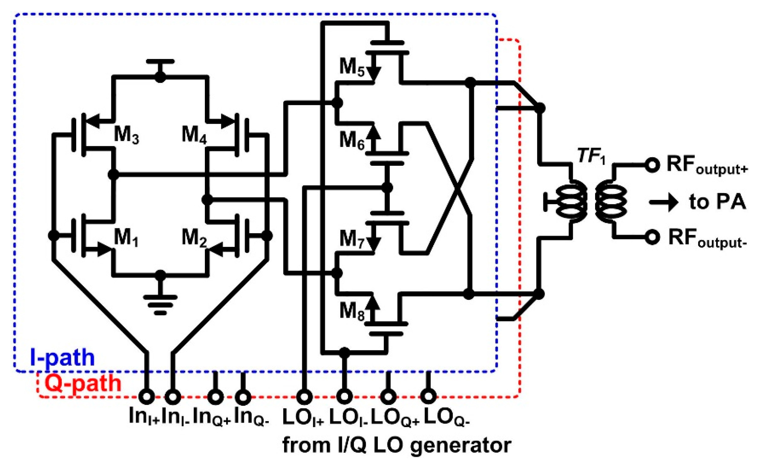
Figure 2 presents the proposed I/Q up-conversion mixer with an inverter-type transconductor. The I/Q modulator shares the load of the I-path and Q-path of the up-conversion mixer to generate the single-side-band (SSB) output signal. An on-chip transformer TF1, which is used as a load for the I/Q modulator, is optimized to achieve inter-stage matching between the output stage of the up-conversion mixer and the input of the power amplifier for maximum power transfer. To increase the output power while reducing the direct current (DC) power consumption of the transmitter front-end circuits, the linearity of the up-conversion mixer should be able to receive large baseband analog signals. Transconductance linearization techniques, such as the derivative superposition method and the multiple-gated transistor (MGTR) technique, can be employed to improve the linearity of the up-conversion mixer [9,10]. However, because the baseband analog I/Q signals of the DAC are connected through direct coupling to the input of the I/Q up-conversion mixer, it is difficult to apply the transconductance linearization technique to the up-conversion mixer, which has to apply different DC bias voltages to the gate of the main transistor and the auxiliary transistor. Therefore, a linearization technique suitable for the up-conversion mixer is proposed that utilizes the concept of complementary CMOS parallel push-pull (CCPP) [11].
As is already known, an inverter-type transconductor composed of NMOS and PMOS has larger transconductance than a conventional NMOS transconductor at the same DC current consumption [12,13,14]. Additionally, a single-ended inverter-type amplifier has higher input-referred second-order intercept point (IIP2) performance due to the complementary characteristics of NMOS and PMOS than a conventional single-ended NMOS common-source amplifier [15].
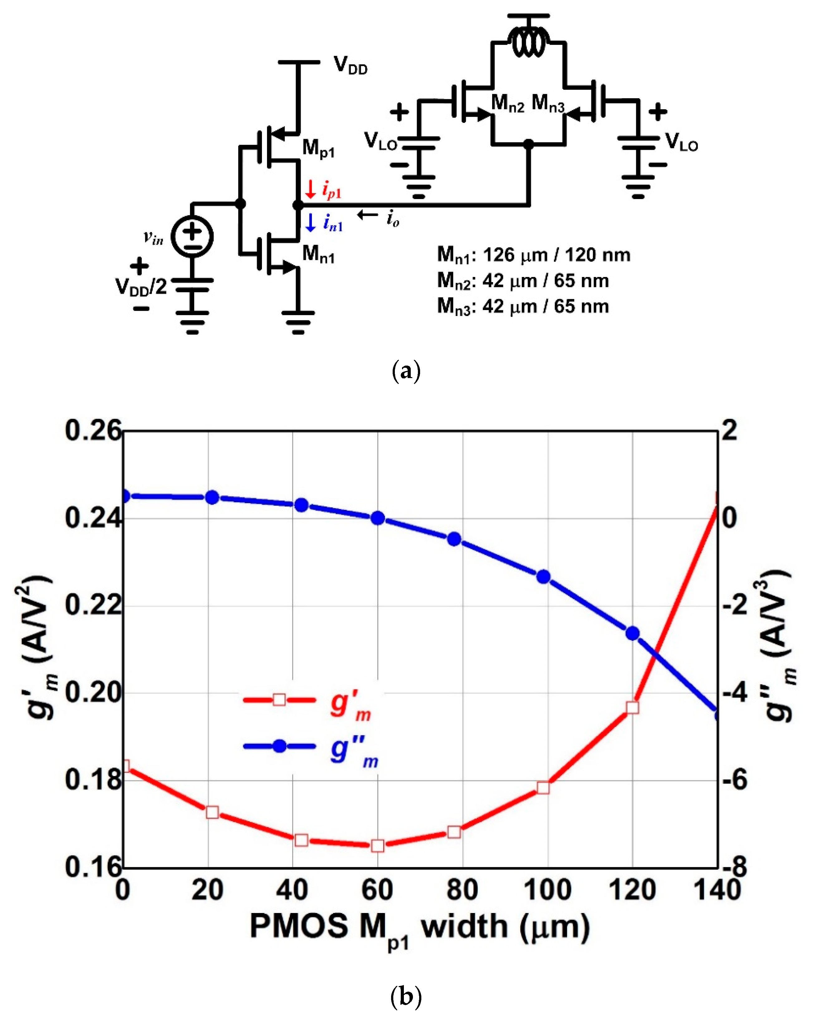
In this paper, we propose the inverter transconductor to obtain a high input-referred third-order intercept point (IIP3). As shown in Figure 3a, if a small signal input voltage v i n is applied to the inverter transconductance stage of the up-conversion mixer, the small signal drain currents of NMOS Mn1 and PMOS Mp1 can be expressed as
i n 1 = g m . n v i n + g m . n v i n 2 + g m . n v i n 3 + ,
i p 1 = g m . p ( v i n ) + g m . p ( v i n ) 2 + g m . p ( v i n ) 3 + ,
where g m is the first derivative and g m is the second derivative of the transconductance g m with respect to the small signal input voltage v i n , respectively. The process of deriving g m and g m is described in detail in [11,15]. The small signal output current is expressed as
i o = i n 1 i p 1 = ( g m 1 + g m 2 ) v i n + ( g m . n g m . p ) v i n 2 + ( g m . n + g m . p ) v i n 3 +
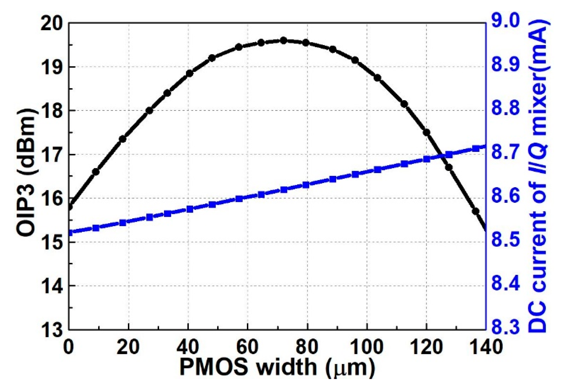
In (3), it is difficult to make the second derivative and third derivative of the small signal output current zero at the same time because the optimum condition for g m . n = g m . p is different from the optimum condition for g m . n = g m . p . The second-order nonlinearity and third-order nonlinearity of the CMOS circuit are dominated by the g m and   g m nonlinearity, respectively [11]. Even though the second derivative of the small signal current is not zero, as shown in Figure 3b, the differential characteristics of the double-balanced up-conversion mixer shown in Figure 2 can lead to high IIP2 performance due to the double-balanced up-conversion mixer. Therefore, we choose the proper PMOS Mp1 transistor size to meet the optimum condition, under which the g m . n term of NMOS can be cancelled by the g m . p term of PMOS. It can make the proposed up-conversion mixer achieve high IIP3 performance. As shown in Figure 3b, when the width of PMOS Mp1 with a channel length of 65 nm is approximately 60 μm, the third derivative of the small signal output current io is zero. Figure 4 shows the simulated output-referred third-order intercept point (OIP3) of the proposed up-conversion mixer according to the width of PMOS Mp1 with a channel length of 65 nm. The highest OIP3 performance of the up-conversion mixer is achieved when the width of PMOS MP1 with a channel length of 65 nm is approximately 70 μm, which is slightly different from the optimum width of 60 μm of the inverter PMOS transistor from the small signal input voltage output current analysis in (3), because NMOS switching transistors’ nonlinearity exists. The proposed up-conversion mixer achieves more than 4 dB OIP3 improvement in comparison to the conventional up-conversion mixer with an NMOS transconductor.
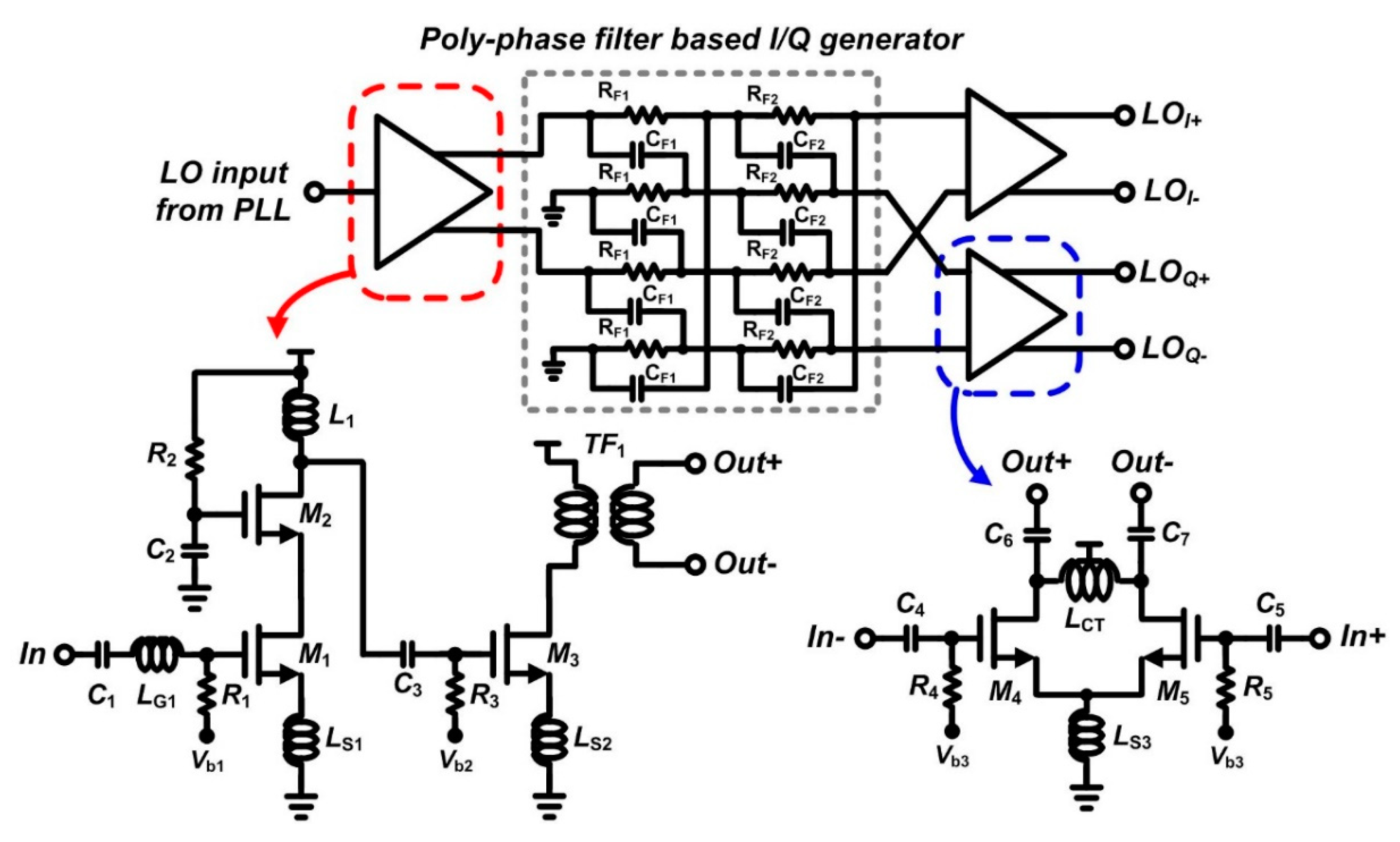
Figure 5 shows a simplified schematic of the proposed I/Q LO generation circuit. The proposed I/Q LO generation circuit is composed of a single-ended cascode amplifier, a single-to-differential common-source amplifier, a 2nd-order RC polyphaser filter (PPF), and two differential common-source amplifiers. To generate the I/Q LO signals, the first-order RC PPF composed of resistor RF1 and capacitor CF1 is used in the RF band whose frequency is lower than the millimeter-wave band, and the mismatch characteristics of RF1 and CF1 determine the I/Q balancing performance of the LO generator [16]. The resistance and capacitance are set at 1/2π(RF1CF1) to the desired operating frequency. In RF bands with relatively low frequencies, line inductance is usually negligible because the impedance of line inductance by metal routing is small. However, even in the case of metal routing with a small line inductance, the corresponding impedance cannot be neglected at the millimeter-wave frequency, so line inductance by metal routing must be considered.
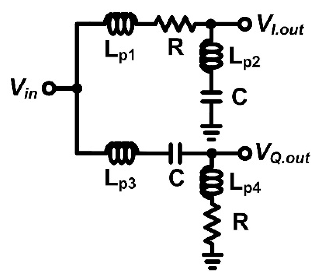
Figure 6 shows the simplified 1st-order poly-phase filter including parasitic line inductance (Lp1, Lp2, Lp3, and Lp4) by metal routing to connect the resistors and capacitors. The transfer function of the 1st-order poly-phase filter can be expressed as
V I , o u t ( ω ) V i n ( ω ) = ( 1 ω 2 C ( L p 1 + L p 2 ) ) · ( 1 ω 2 L p 2 C ) + j ( ω 3 L p 2 R C 2 ω R C ) ( 1 ω 2 C ( L p 1 + L p 2 ) ) 2 + ω 2 R 2 C 2
V Q , o u t ( ω ) V i n ( ω ) = ω 4 L p 4 C 2 ( L p 3 + L p 4 ) + ω 2 ( R 2 C 2 L p 4 C ) + j ( ω R C ω 3 L p 3 R C 2 ) ( 1 ω 2 C ( L p 3 + L p 4 ) ) 2 + ω 2 R 2 C 2
To ensure that the LO signals of the I path and the Q path have the same magnitude and 90 degrees’ difference, the following conditions are derived from Equations (4) and (5):
L p 1 = L p 2 = L p 3 = L p 4
ω = 1 C ( C R 2 + L p 1 + L p 2 )
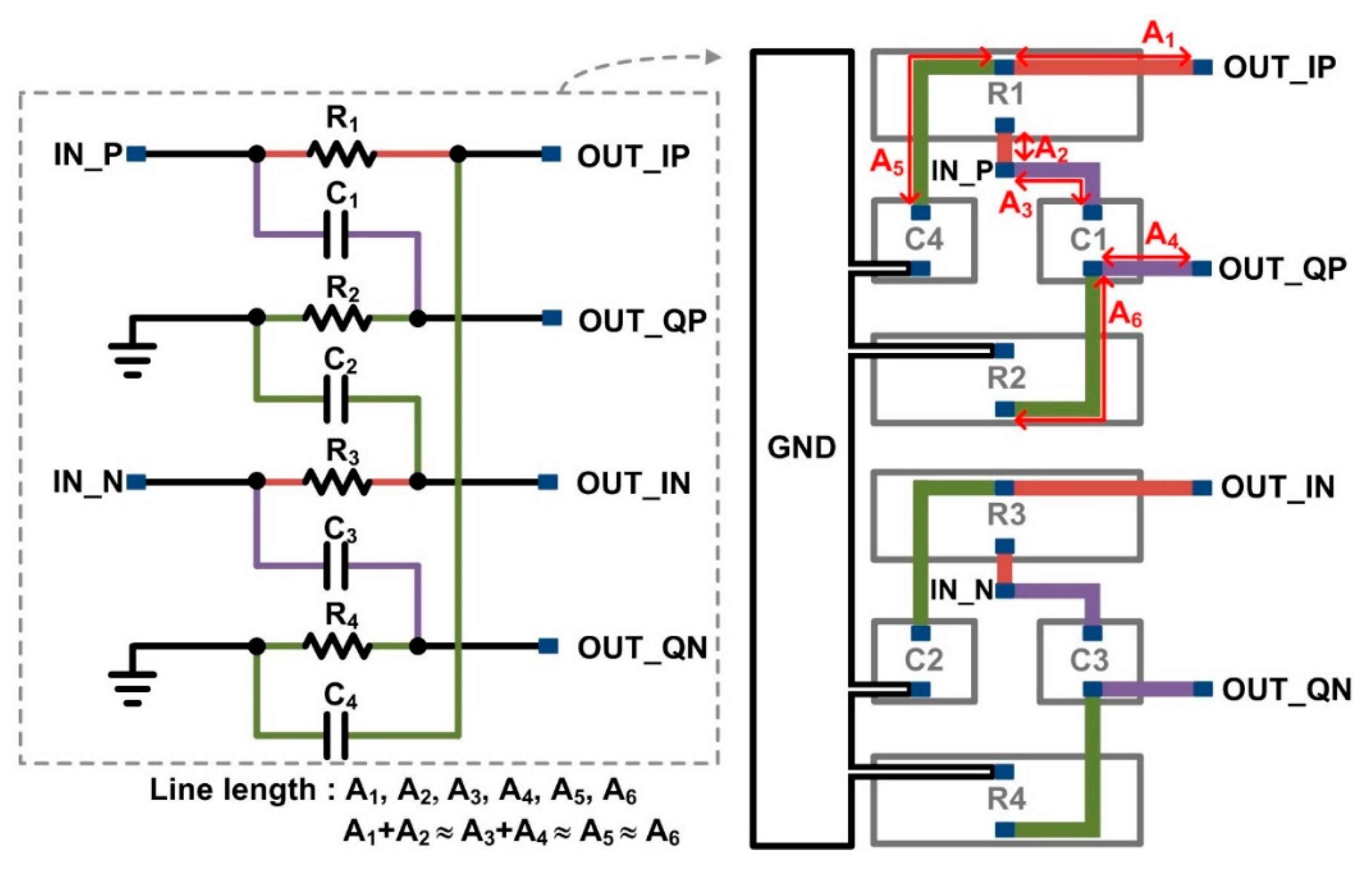
From Equation (6), the lengths of the connecting line should be as similar as possible so that the parasitic inductance value is the same. Figure 7 presents a layout of 1st-order poly-phase filter of Figure 5, which is an example to make the lengths (A1 + A2 ≈ A3 + A4 ≈ A5 ≈ A6) of the connecting lines similar. In addition, the poly-phase filter is designed by determining the resistance value and the capacitance value of the poly-phase filter in consideration of the parasitic inductance value from Equation (7). In our design, the inductance of L1~L4 is approximately 20 pH. As shown in Figure 8, the proposed poly-phase filter-based I/Q LO generation circuits achieve good balancing I/Q performance by considering the parasitic inductances of the connecting lines in the schematic design and layout. In general, a mixer circuit is designed to operate in a region which is insensitive to the amplitude variations of the LO signals. Therefore, although the magnitude mismatch between the I- and Q-paths of the proposed poly-phase filter-based I/Q LO generation circuits is less than 0.25 dB, the simulated gain of the designed I- and Q-paths of the up-conversion mixer is the same.
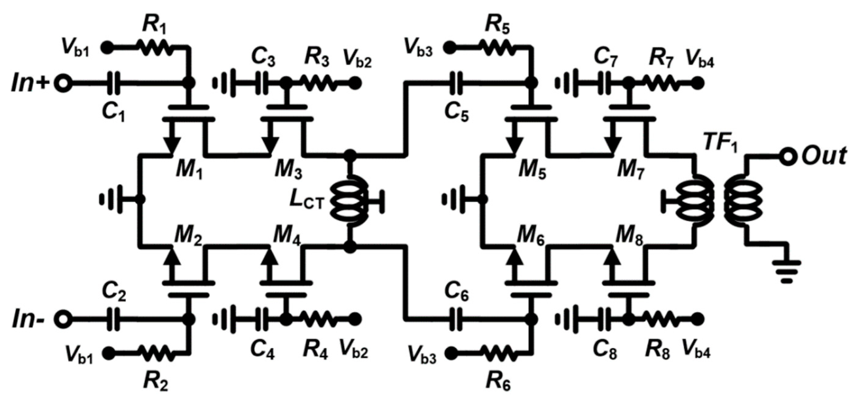
Figure 9 shows a simplified schematic of the two-stage power amplifier. The power amplifier consists of a driver-stage amplifier and a power-stage amplifier [17,18]. The driver-stage amplifier employs a cascode structure and a symmetric inductor with a center tap, which is connected to a supply voltage of 2.1 V. The power-stage amplifier adopts the cascode structure and a 3:1 on-chip transformer for output 50-Ω matching. The simulated OP1dB and OIP3 of the two-stage power amplifier are 9.7 dBm and 17 dBm, respectively. The simulated peak PAE of the two-stage power amplifier is 15%.

3. Results

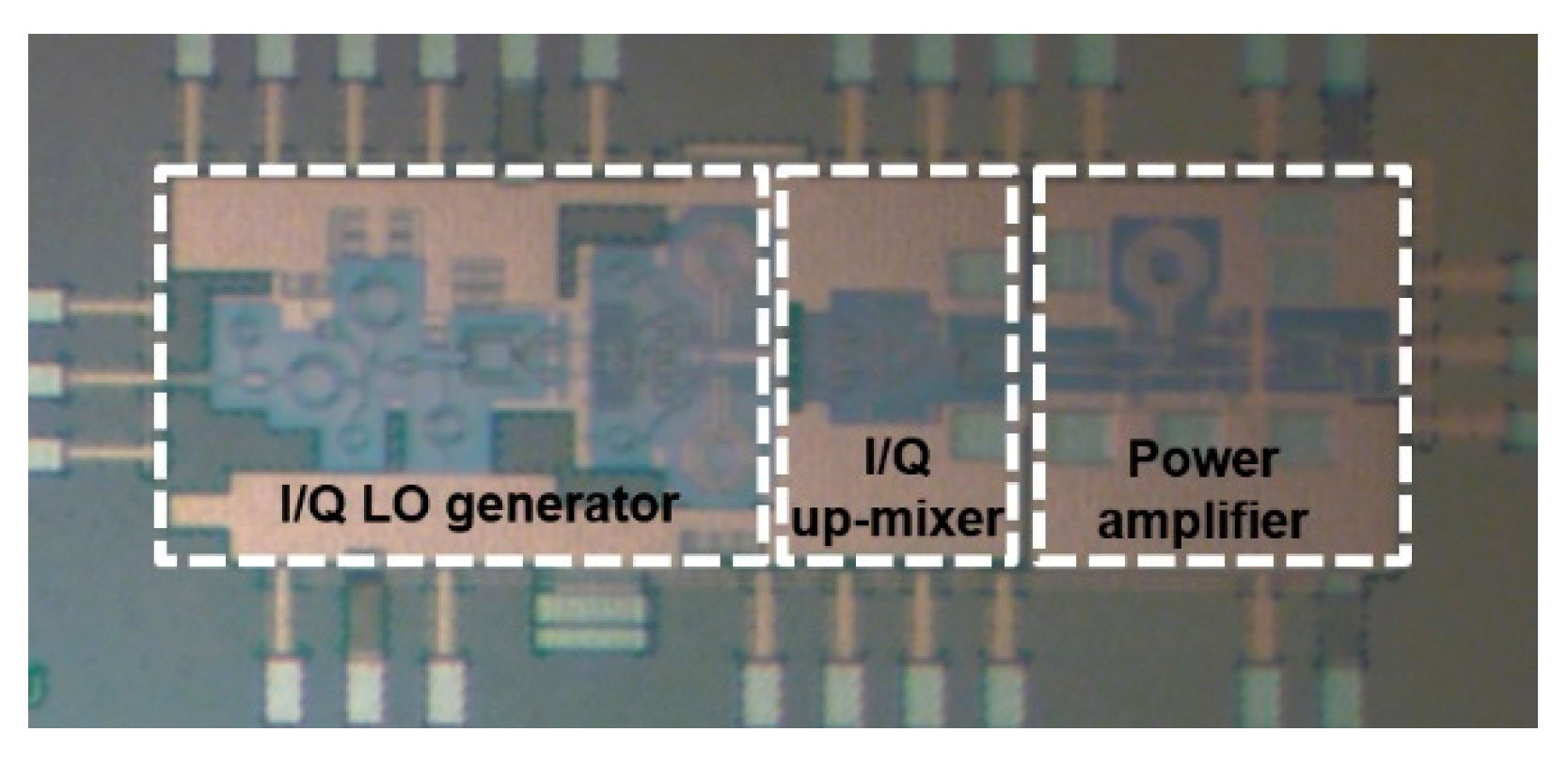
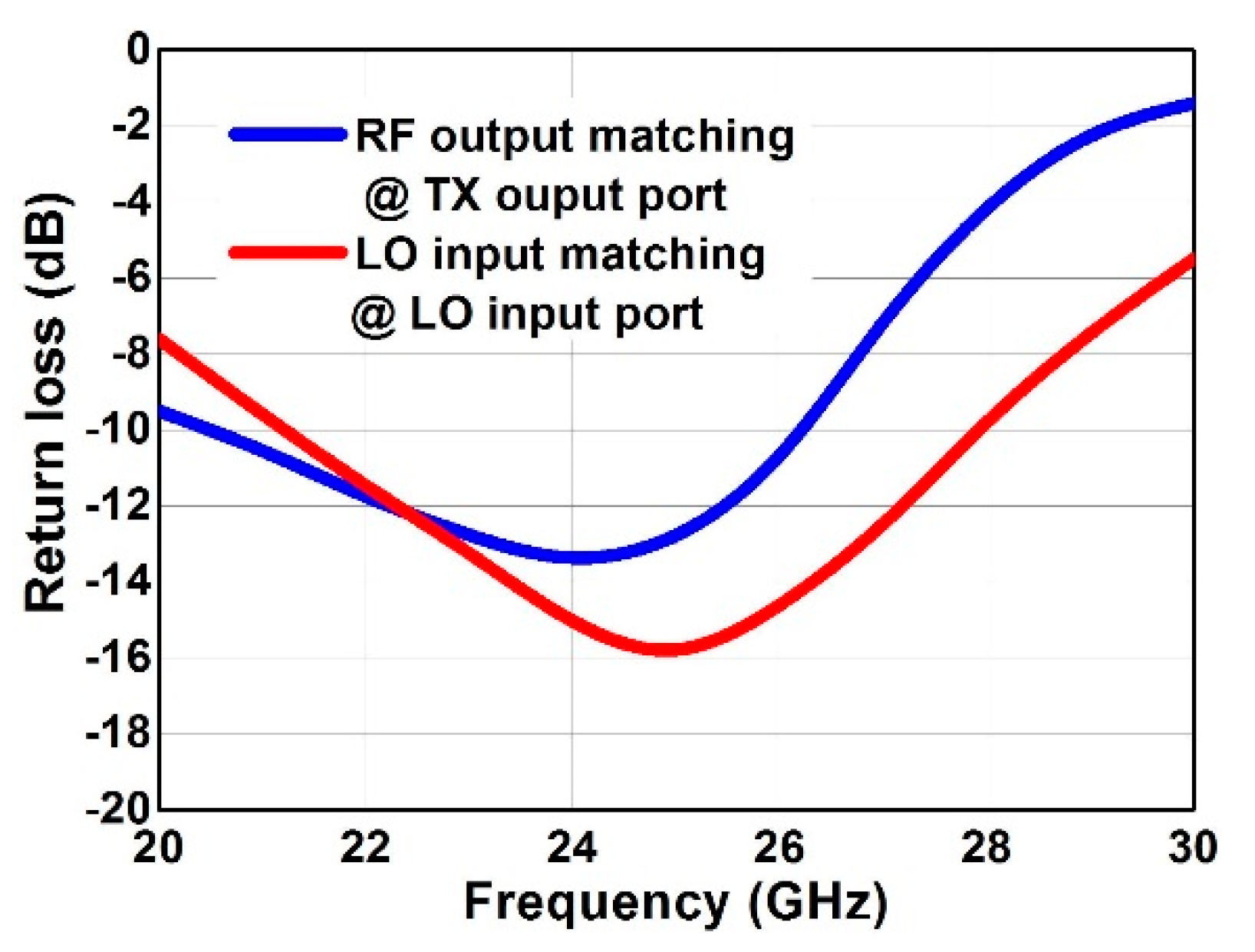
The proposed 24 GHz transmitter was implemented in a 1-poly 8-metal 65-nm RF CMOS process. Figure 10 shows a photograph of the proposed 24-GHz transmitter. The chip size is 1.5 mm × 0.8 mm, including pads. The current consumption of an I/Q up-conversion mixer and an I/Q LO generator is 8.6 mA and 11.4 mA at a 1.2-V supply voltage, respectively. The current consumption of the power amplifier is 60 mA at a 2.1-V supply voltage. In our measurement, −10 dBm of LO power was applied at the LO input port. Figure 11 shows the measured return losses of the proposed 24-GHz transmitter. The return losses of the RF output and LO input were less than −10 dB at the operating frequencies.
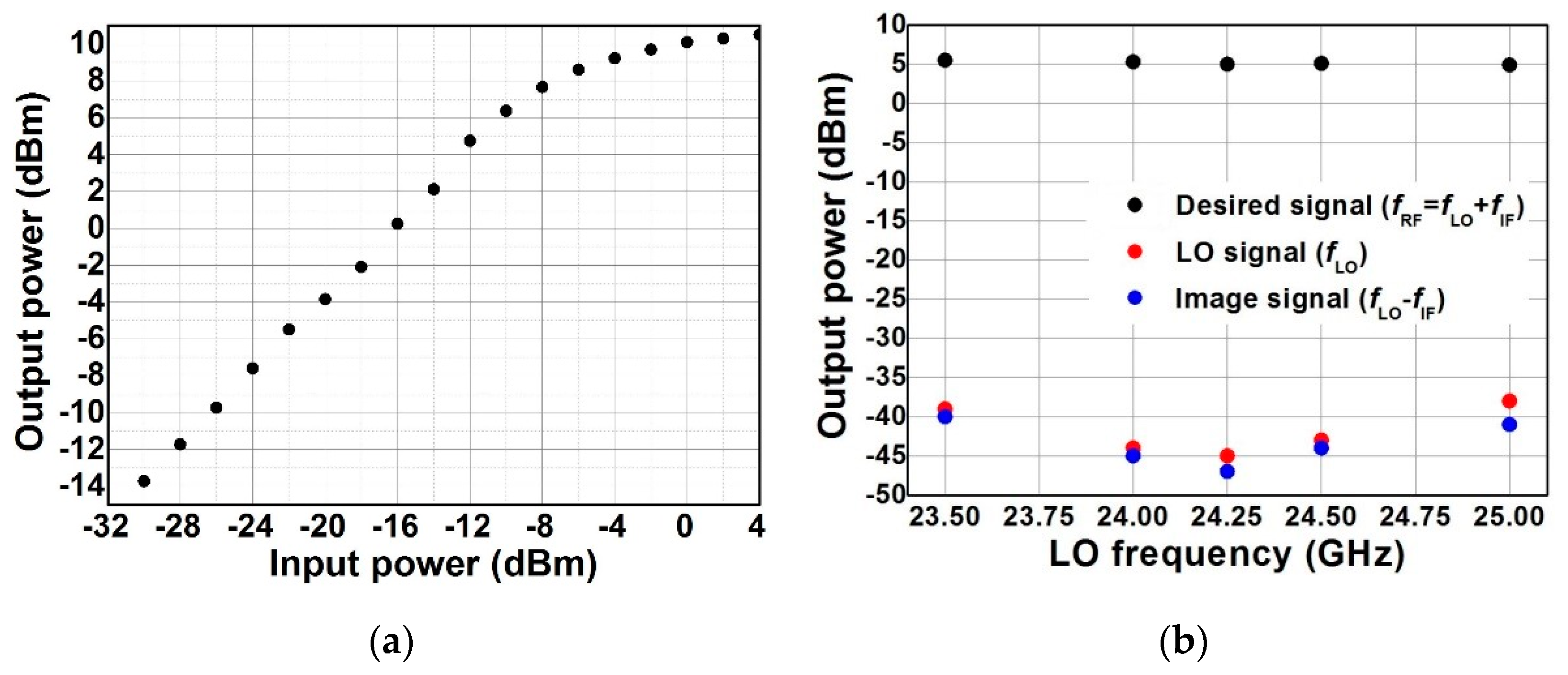
Figure 12 shows the measured output signal power of the transmitter according to the input signal power and the measured output spectrum of the transmitter according to various LO frequencies. As seen in Figure 12a, the measured OP1dB of the transmitter was approximately 8.6 dBm. The LO leakage and image rejection ratio were less than −48 dBc at the operating frequencies from 24 GHz to 24.5 GHz thanks to the proposed I/Q LO generation circuits. The LO leakage performance was achieved by symmetric I/Q layout and good balanced differential LO signals, which were verified by post-layout simulation and full electromagnetic simulation including all passive components and routing lines.
Table 1 summarizes the measured results of the proposed 24-GHz transmitter and compares its performance with that of other published millimeter-wave (mm-wave) transmitters [19,20,21]. The proposed transmitter exhibits higher LO leakage and image rejection ratio with compatible OP1dB performance and power consumption than other CMOS mm-wave transmitters.

4. Conclusions

A 24-GHz direct up-conversion transmitter with a highly linear I/Q up-conversion mixer and a balanced I/Q LO generator was proposed for in-cabin radar applications. It was designed and fabricated in a 65-nm RF CMOS process and provides high linearity and I/Q balancing characteristics. The proposed transmitter exhibits a high OP1dB, a high LO leakage rejection, and a high image rejection ratio with low power consumption. Therefore, the proposed transmitter is suitable for an in-cabin radar transceiver.

Author Contributions

S.L. (Suyeon Lee), Y.J., G.P., J.M., and S.L. (Seungjik Lee) performed the circuit design and experiments under the supervision of I.N., O.L. provided significant comments and technical feedback throughout the research. I.N. and H.M. conceived the methodology and wrote the paper. All authors analyzed the data and edited the manuscript. All authors have read and agreed to the published version of the manuscript.

Funding

This work was supported by the National Research Foundation of Korea (NRF) grant funded by the Ministry of Science and ICT (NRF-2019R1A2C1090935), and Basic Science Research Program through the National Research Foundation of Korea (NRF) funded by the Ministry of Education (No. NRF-2017R1D1A1B03031357), Korea.

Acknowledgments

The CAD tools were supported by IDEC.

Conflicts of Interest

The authors declare no conflict of interest.

References

  1. Droitcour, A.; Lubecke, V.; Lin, J.; Boric-Lubecke, O. A microwave radio for doppler radar sensing of vital signs. In Proceedings of the 2001 IEEE MTT-S International Microwave Symposium Digest, Phoenix, AZ, USA, 20–25 May 2001; pp. 175–178. [Google Scholar]
  2. Xiao, Y.; Lin, J.; Boric-Lubecke, O.; Lubecke, M. Frequency-tuning technique for remote detection of heartbeat and respiration using low-power double-sideband transmission in the ka-band. IEEE Trans. Microw. Theory Tech. 2006, 54, 2023–2032. [Google Scholar] [CrossRef]
  3. Park, J.-H.; Jeong, Y.-J.; Lee, G.-E.; Oh, J.-T.; Yang, J.-R. 915-MHz continuous-wave doppler radar sensor for detection of vital signs. Electronics 2019, 8, 855. [Google Scholar] [CrossRef] [Green Version]
  4. Gu, C.; Li, C. Assessment of human respiration patterns via noncontact sensing using doppler multi-radar system. Sensors 2015, 15, 6383–6398. [Google Scholar] [CrossRef] [PubMed] [Green Version]
  5. Andersen, N.; Granhaug, K. A 188-mW pulse-based radar SoC in 55-nm CMOS for non-contact human vital signs detection. IEEE J. Solid State Circuits 2017, 52, 3421–3433. [Google Scholar] [CrossRef]
  6. Kim, D. Wireless vital signal tracking for drivers using micro-doppler seatback radar. In Proceedings of the 2018 9th IFIP International Conference on New Technologies, Mobility and Security (NTMS), Paris, France, 26–28 February 2018; pp. 1–5. [Google Scholar]
  7. Brenna, G.; Tschopp, D.; Pogin, J.; Kouchev, I.; Huang, Q. A 2-GHz carrier leakage direct-conversion WCDMA transmitter in 0.13-μm CMOS. IEEE J. Solid State Circuits 2004, 39, 1253–1262. [Google Scholar] [CrossRef]
  8. Nam, I.; Choi, K.; Lee, J.; Cha, H.-K.; Seo, B.-I.; Kwon, K.; Lee, K. A 2.4-GHz low-power low-IF receiver and direct-conversion transmitter in 0.18-μm CMOS for IEEE 802.15.4 WPAN applications. IEEE Trans. Microw. Theory Tech. 2007, 55, 682–689. [Google Scholar] [CrossRef]
  9. Webster, D.; Scott, J.; Haigh, D. Control of circuit distortion by the derivative superposition method. IEEE Microw. Guided Wave Lett. 1996, 6, 123–125. [Google Scholar] [CrossRef]
  10. Im, D.; Nam, I.; Lee, K. A low power broadband differential low noise amplifier employing noise and IM3 distortion cancellation for mobile broadcast receivers. IEEE Microw. Wirel. Compon. Lett. 2010, 20, 566–568. [Google Scholar] [CrossRef]
  11. Nam, I.; Kim, B.; Lee, K. CMOS RF amplifier and mixer circuits utilizing complementary characteristics of parallel combined NMOS and PMOS devices. IEEE Trans. Microw. Theory Tech. 2005, 53, 1662–1671. [Google Scholar] [CrossRef]
  12. Karanicolas, A. A 2.7 V 900 MHz CMOS LNA and mixer. IEEE J. Solid State Circuits 1996, 31, 1939–1944. [Google Scholar] [CrossRef]
  13. Choi, C.; Kwon, K.; Nam, I. A 370 μW CMOS MedRadio receiver front-end with inverter-based complementary switching mixer. IEEE Microw. Wirel. Compon. Lett. 2016, 26, 73–75. [Google Scholar] [CrossRef]
  14. Hwang, I.-C. Low-noise high-PSRR and positive-TC voltage reference for a temperature- and supply-compensated CMOS ring oscillator. IEIE Trans. Smart Process. Comput. 2019, 8, 331–334. [Google Scholar] [CrossRef]
  15. Im, D.; Nam, I.; Kim, H.-T.; Lee, K. A wideband CMOS low noise amplifier employing noise and IM2 distortion cancellation for a digital TV tuner. IEEE J. Solid State Circuits 2009, 44, 686–698. [Google Scholar] [CrossRef]
  16. Kaukovuori, J.; Stadius, K.; Ryynanen, J.; Halonen, K.A.I. Analysis and design of passive polyphaser filters. IEEE Trans. Circuits Syst. I 2008, 55, 3023–3037. [Google Scholar] [CrossRef]
  17. Kim, D.-M.; Kim, D.; Jeong, H.-G.; Im, D. A reconfigurable CMOS inverter-based stacked amplifier with antenna impedance mismatch compensation for low power short-range wireless communications. Electronics 2020, 9, 562. [Google Scholar] [CrossRef] [Green Version]
  18. Choi, S.-E.; Ahn, H.; Hur, J.; Kim, K.-W.; Nam, I.; Choi, H.; Lee, O. A fully integrated compact outphasing CMOS power amplifier using a parallel-combining transformer with a tuning inductor method. Electronics 2020, 9, 257. [Google Scholar] [CrossRef] [Green Version]
  19. Kim, B.; Kim, S.; Lee, Y.; Kim, S.; Shin, H. A 28 GHz quadrature up-conversion transmitter in 65 nm CMOS for 5G mm Wave Radio. In Proceedings of the International SoC Design Conference, Jeju, Korea, 6–9 October 2019; pp. 2163–2169. [Google Scholar]
  20. Lee, H.; Park, M.; Min, B. A 26-GHz transmitter front-end using double quadrature architecture. PLoS ONE 2019, 14, e0216474. [Google Scholar] [CrossRef] [PubMed]
  21. Cao, C.; Ding, Y.; Yang, X.; Lin, J.-J.; Wu, H.-T.; Verma, A.K.; Lin, J.; Martin, F. A 24-GHz transmitter with on-chip dipole antenna in 0.13-μm CMOS. IEEE J. Solid State Circuits 2008, 43, 1394–1402. [Google Scholar] [CrossRef]
Figure 1. Block diagram of the proposed 24-GHz direct-conversion transmitter.
Electronics 09 02005 g001
Figure 2. Simplified schematic of the proposed I/Q up-conversion mixer. (For simplicity, Q-path up-conversion mixer, direct current (DC) bias resistors, and alternating current (AC) coupling capacitors for switching transistors are omitted).
Electronics 09 02005 g002
Figure 3. (a) Inverter-type transconductor (NMOS Mn1 and PMOS Mp1) and switching transistors Mn2 and Mn3 from up-conversion mixer, (b)   g m and g m of small signal output current io of inverter-type transconductor over the width of PMOS Mp1 with a channel length of 65 nm.
Electronics 09 02005 g003
Figure 4. Simulated output-referred third-order intercept point (OIP3) performance and DC current consumption of the proposed up-conversion mixer over the width of PMOS Mp1 with a channel length of 65 nm.
Electronics 09 02005 g004
Figure 5. Simplified schematic of the proposed poly-phase filter-based I/Q LO generation circuits.
Electronics 09 02005 g005
Figure 6. Simplified 1st-order poly-phase filter including parasitic line inductance by metal routing.
Electronics 09 02005 g006
Figure 7. Layout diagram for 1st-order poly-phase filter.
Electronics 09 02005 g007
Figure 8. Simulated magnitude and phase mismatch between the I- and Q-paths of the proposed poly-phase filter-based I/Q LO generation circuits.
Electronics 09 02005 g008
Figure 9. Simplified schematic of the two-stage power amplifier.
Electronics 09 02005 g009
Figure 10. Chip photograph of the fabricated 24-GHz transmitter.
Electronics 09 02005 g010
Figure 11. Measured return loss versus operating frequencies.
Electronics 09 02005 g011
Figure 12. (a) Measured output power at RF output frequency of 24 GHz, (b) measured output spectrum at 5 dBm of desired RF signal output. (IF frequency used was 10 MHz).
Electronics 09 02005 g012
Table 1. Performance comparison with CMOS mm-wave transmitters.
Reference[19][20][21]This Work
Frequency (GHz)28262424
OP1dB (dBm)5.810-8.6
LO leakage (dBc)−31−21.7−42−48
Image rejection ratio (dBc)−37−28.9−24−49
Power consumption (mW)111267118150
Technology65-nm CMOS65-nm CMOS130-nm CMOS65-nm CMOS
Publisher’s Note: MDPI stays neutral with regard to jurisdictional claims in published maps and institutional affiliations.