Article

Sacrificial Volume Materials for Small Hole Generation in Low-Temperature Cofired Ceramics

1
IMT Atlantique, Lab-STICC, UMR CNRS 6285, F-29238 Brest, France
2
The ECIT Institute, Queen’s University Belfast, Belfast BT3 9DT, UK
3
The Polymer Processing Research Centre, Queen’s University Belfast, Belfast BT9 5AH, UK
*
Author to whom correspondence should be addressed.
Electronics 2020, 9(12), 2168; https://doi.org/10.3390/electronics9122168
Submission received: 28 October 2020 / Revised: 4 December 2020 / Accepted: 14 December 2020 / Published: 17 December 2020
(This article belongs to the Special Issue LTCC for Space, Imaging, Telecommunication, and Medical Applications)

Abstract

:
The creation of hole, cavity or channel structures in low-temperature cofired ceramics (LTCCs), using different sacrificial volume materials (SVMs) was tested. The main functionality of the SVMs should be: easy application into the holes; protection of holes during lamination; uninhibited lamination between layers; and, during firing should burn out before the pores of the LTCCs close, to leave the empty holes clear of any residue. Five different materials were tested—hydroxyethyl cellulose (HEC) 2 wt%, HEC 5 wt%, agar-agar, gelatin, and commercial carbon paste—and compared to a reference sample where no SVMs were used. In all cases, lamination parameters were minimised in order to preserve the tested hole structures. Matrixes with holes ranging from 158 to 268 µm, with pitches of 573 µm in a green state, were tested. The agar-agar caused ceramic deformation as a result of thermal burst during firing and the lamination between the layers was compromised. The carbon paste was difficult to handle, requiring extra equipment for hole filling and incomplete filling of the larger holes. Traces of carbon paste were left as a landing pad on top of the holes, inhibiting lamination at these areas. The gelatin and the 2 wt% and 5 wt% hydroxyethylcellulose (HEC 2 wt% and HEC 5 wt%) filled all holes completely, and also worked as adhesive-assisted lamination (AAL) materials with excellent lamination between layers. Excellent lamination was also observed in the no-SVM case. Thermogravimetric analysis (TGA) and scanning electron microscopy (SEM) with energy-dispersive X-ray (EDX) analyses established that, for all SVMs tested, the remaining residue is negligible after firing. As a result, the HEC 2 wt% material was considered ideal for use as an SVM.

1. Introduction

Low-temperature cofired ceramics (LTCCs) have been around for decades; however, their development has come on step by step. In 1960, the Radio Corporation of America (RCA) filed a patent on the creation of ceramic tapes from slurry [1]. Before this patent came about, ceramic circuits were created by repeating the following steps: spraying a slurry on a support, drying the slurry, screen printing metal paste onto the dried slurry, drying and then starting all over again. This induced the problem of solvent penetration in the lower layers when spraying on the next layer of slurry. By using this method to create ceramic tapes, known as tape casting, each tape could be screen printed and stacked without any solvent penetrating into the lower layers. This excellent progress stemmed from earlier fabrications mainly used to create capacitors. However, the firing temperature was still too high to use gold or silver metal pastes; therefore, electrode materials, such as molybdenum, tungsten, palladium or platinum, were used. In 1973, the firing temperature was lowered below 1200 °C by changes in the slurry composition, as presented in a patent by Nakayama, [2]. Before [2], the ceramic material was barium–titanate-based, however, the new composition included bismuthate glass frit, where BiO2, PbO, and SiO2/B2O3 were combined to lower the firing temperature. In 1978, Du Pont filed a patent where using alumina, Al2O3, mixed with SiO2, was proposed to further lower the firing temperature while adding Na2O, K2O or Li2O to lower the softening point [3]. These adjustments allowed for a real low-temperature firing—i.e., below 1000 °C—where excellent electrical conductors, such as gold and copper, could be used as electrode metals.
Nowadays, LTCCs represent a well-known ceramic multilayer design platform used in all types of device, used with applications in telecommunication, power electronics, space, radar and imaging applications, as well as microfluidics, to mention a few. LTCC materials (tapes and pastes) are either proprietary and are created in-house, as is the case for companies such as KOA [4], TDK [5] or Kyocera [6], or are commercially available, as is the case of Du Pont [7] or Ferro [8].
One interesting feature of the LTCC is its three-dimensional design capacity, with the possibility to include cavities in order to place chips not only on the top and bottom surface of the microelectronic package, but in cavities in order to shorten the lengths of the wire bonding, as is typical for microwave LTCC modules—e.g., [9]. However, another three-dimensional application is the internal microfluidic channel, which allows fluid to flow inside the substrate for diverse applications, such as in gas and flow sensors, heaters, and humidity sensors, [10,11] gapped waveguide microfluidic applications [12] or in thermal management devices, such as micro heat pipes [13,14,15], to give a few examples.

1.1. Overview of Existing Methods

The manufacture of devices which include cavities or channels, follows the normal LTCC fabrication steps: blanking via cavity forming, filling, conductor, and passives printing, stacking, lamination, cofiring and singulation. The cavities or channels, whether they are internal or external, must be protected during lamination, so as to avoid being deformed. For this, several methods exist, such as:
  • Insertion of sacrificial volume materials (SVMs) combined with a two-step lamination procedure [11,16];
  • Insertion of SVMs combined with hot lamination [17,18];
  • Temporary inserts combined with hot lamination [19,20,21,22] (the inserts are taken out or chemically etched after firing);
  • Use of carbon-based SVMs also called fugitive materials (FMs), combined with hot lamination [17,23,24,25,26];
  • Cold chemical lamination (CCL) [16,27];
  • Adhesive-assisted lamination (AAL) [28,29] with reduced lamination parameters.
In general, these methods allow for the creation of internal cavities or microfluidic channels of widths several times the tape thickness; hence, the cut-out of fugitive tape or other SVM materials, as well as the filling procedure, are quite easily done. However, when it comes to creating dimensional features of 150 µm or smaller, e.g., micro heat pipes in [15], the filling becomes more complicated, especially if the SVM is to fill the cavity/hole/groove shape without overfilling and flooding onto the tape’s surface. A good indication of how to achieve empty miniature shapes in LTCCs may be found in [28], where adhesive-assisted and almost pressureless lamination is discussed for the fabrication of microfluidic channels in LTCCs. Liquid solutions, such as liquid polymethylmethacrylate (PMMA), polyvinyl acetate (PVA) and hydroxyethyl cellulose (HEC) are used in a first step to “cold laminate” the layers together. This is followed by filling the channels by a vacuum procedure, before performing full pressure lamination, prior to firing. However, the liquid PMMA showed poor performance and the PVA and HEC resulted in sagging in the produced structures. Sagging is a non-concern in cases where the hole or cavity structure’s lateral size is in the order of the tape thickness. This AAL method is also mentioned in [29], where organic liquids, such as natural honey, glucose and polyester resins, are mentioned to serve as gluing agents between layers.
A further structure unmentioned in the cited papers is an LTCC structure covered with small unfilled holes. These are used when forming a low-permittivity material from a medium permittivity tape material, as was done in [30], or when forming different substrate integrated circuits, as proposed in [31]. This is also the main goal for the research performed here. For such a structure, an adhesive that works as AAL would reduce the lamination parameters. With lower pressure, the holes may be preserved. If unsuccessful, an alternative would be if the same material could be used as an inter-layer adhesive and at the same time be readily filled into the holes to protect them during lamination and then burn off during the firing cycle. The SVM/AAL material should burn off well before the pores close in the LTCC tape, a process that typically begins after 700 °C during firing [24].

1.2. Requirements

The following list outlines the requirements for an ideal SVM that is intended to generate a multitude of holes in an LTCC structure:
  • Ease of use, i.e., simple application and filling method for different hole shapes (or grooves or others);
  • Potential for multi-hole filling with a diameter equal or larger than 127 µm on a 127 µm thick tape over a large surface (typically 50 mm × 50 mm here);
  • Remain in place and retain its initial shape during lamination;
  • Allow for a good quality lamination (adhesive assisted or not) with low lamination parameters;
  • No negative effect on the tape or metal layers (coloration, dissolution, etc.);
  • Burn off during firing at temperatures lower than 700 °C to leave no residue;
  • Non-hazardous to health or environment;
  • Low cost and widely available.
From previous literature [28], possible candidates for the SVM are PVA, HEC or starch corn powder [23]. In [23] the tape was kept on the mylar layer during the filling of cavities to serve as a protective layer. This is incompatible with our general LTCC processing where the mylar layer is removed before laser cutting. In a very comprehensive overview [29], wax, cetyl alcohol and polymeric materials were mentioned, however, wax and cetyl alcohol require melting before application which makes the filling difficult. A further difficulty encountered by the group in previous tests were cetyl alcohol, (melting point at 47 °C) was used, showed the alcohol melting during normal lamination temperatures (~70 °C) and diffused into the tapes, resulting in deformation [32]. Carbon paste [33] could also be used since it is a professional material intended as an FM albeit for screen-printed FM structures between layers than as a hole filler. Other possible materials are agar-agar or gelatin or any other kind of jelly-like material with a high viscosity to allow filling a remain inside the holes without adversely affecting the tape.

2. Materials and Methods

Hole diameters in LTCC are usually equal to the tape thickness used. Here, a 127 µm thick green LTCC tape material was used, with differing hole diameters from 100 µm to 250 µm (post-firing dimensions). The selected SVMs were:
  • HEC 2 wt%
  • HEC 5 wt%
  • agar-agar
  • gelatin
  • carbon paste from C12 [33]
  • no SVM (reference)
The HEC has a Material Safety Data Sheet [34] outlining its safety, the agar-agar and gelatin are used in cooking, allowing them to be considered harmless. The carbon paste contains components that may be irritating or harmful if inhaled or ingested but is included in the study as it will only be used in the LTCC process.
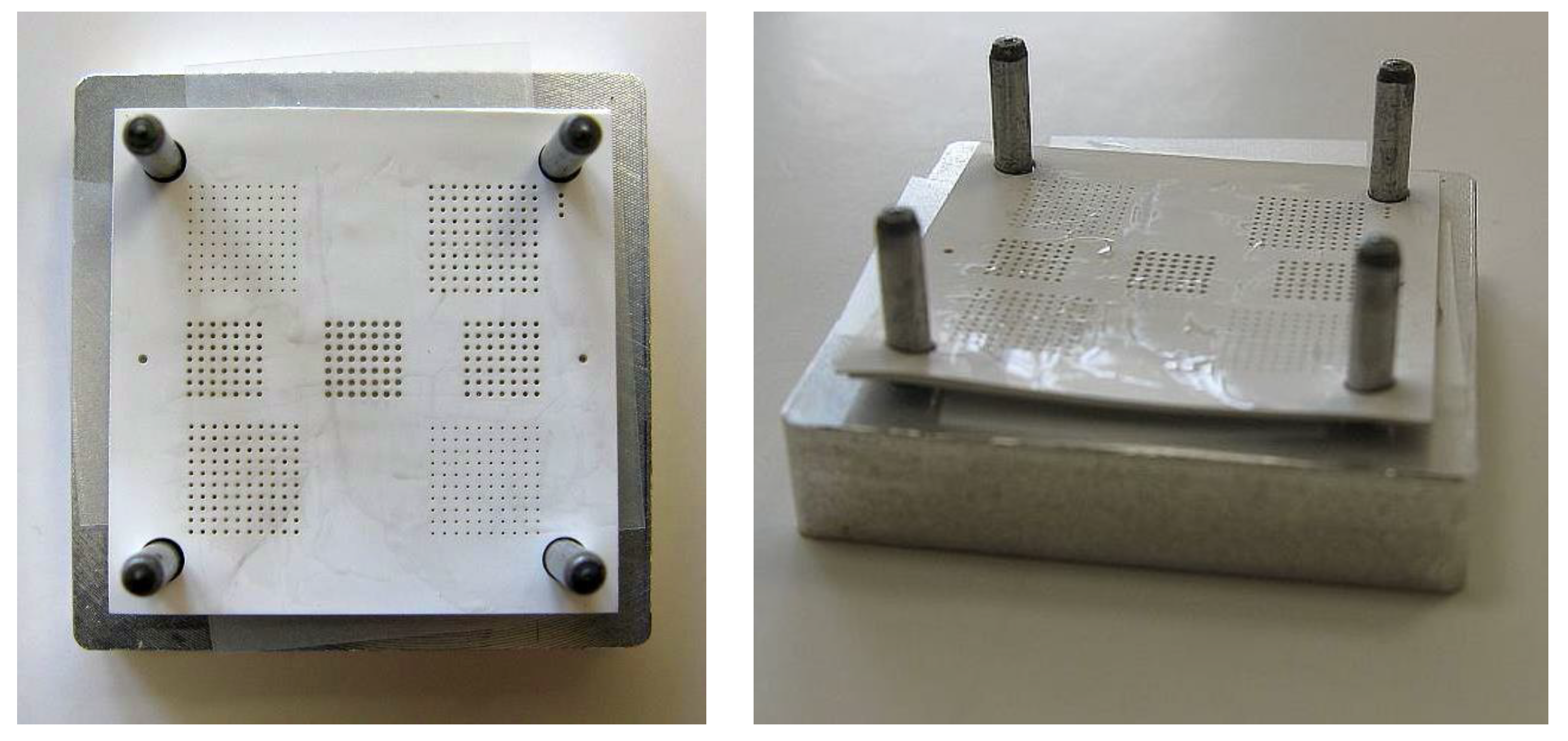
The LTCC tape used was the Ferro A6M-E tape [8] that has a relative permittivity of 5.7 and a loss tangent of less than 0.1% at 10 GHz. This tape is typically used to build millimeter-wave devices. As described earlier, the introduction of a hole pattern over the tapes may allow for the design of new devices. To aid this design, a fully developed fabrication process was required to ensure the specified hole shape and density. In [30] the dimensions for the hole diameter and the pitch were not reported. Also not included was the tape material, production method (including the use of SVM material and lamination method) or who fabricated the device. Here, the test substrate has been designed with different hole diameters keeping the pitch equal in all cases. Three 25.4 mm × 25.4 mm and 127 µm thick tapes were used to generate the test vehicles. The limited number of tapes was chosen in order to minimize cost while still providing information about lamination between layers and protection of the holes. A tape is shown in Figure 1. The holes were cut out by a micromachining tool equipped with a 1064 nm laser (LEM2 from Laser Cheval).

2.1. Fabrication

For the test sample with no SVM, the layers were stacked on the alignment fixture, sealed together at the edges with Nitrocellulose (nail varnish), placed in a vacuum machine for 5 mins before lamination and firing. The carbon paste test sample layers were individually screen printed (400 mesh, 19 µm stainless steel mesh), dried for 10 min in 70 °C, before following the same procedure as the no SVM sample. The agar-agar powder and gelatin sheets were dissolved in heated (40 °C) tap water to a low viscosity jelly, while the HEC was mixed with room temperature deionized water to the right weight percentage. After preparing these liquids, stacking took place within 1 hour, as each liquids’ viscosity changes with time. The change in viscosity was a result of the evaporation of the solvent.
For these four samples, the stacking procedure was as follows; first, protect the alignment fixture with a lamination sheet, then place one LTCC layer onto the fixture, use a spatula to spread the liquid over the surface which simultaneously fills the holes, place a second layer on the fixture, spread the liquid with the spatula over the whole surface, place the third layer on the fixture spread the liquid with the spatula over the surface and finally remove excess liquid from the top layer, remove the stack from the alignment fixture, place it between clean lamination sheets and vacuum treat the stack to remove any air bubbles captured within the structure. An example of the alignment fixture with three layers of LTCC stacked with HEC 2 wt% is shown in Figure 2 below. Slight cambering of the stacked tapes that disappears during the lamination is seen.
All six samples were laminated simultaneously using a uniaxial press from Colorking, with top and bottom plates heated to 62 °C, applying a pressure of 7 MPa for 5 min. These lamination parameters have been chosen after preliminary in house testing inspired by [28] who found that pressure as low as 3 MPa sufficed for their AAL and [15] where 50 °C, 2–5 min and 7 MPa was found to work well for lamination, although in both cases other tapes than the Ferro A6M-E were used. The six samples were placed between lamination foils and pressed simultaneously to avoid any other variation during this step. After lamination, visual analysis was performed to compare the results before and after lamination.
Thereafter, all six samples were fired simultaneously in a Nabertherm programmable static furnace using the standard firing profile reaching 850 °C for 15 min given by the manufacturer [35], however, the cooling is not forced which results in a slower course. The temperature profile is given in Figure 3.
In [24], a prolonged profile having plateau at 680 °C is proposed for carbon paste from ElectroScience Laboratory (ESL).As this study compares different SVMs, the same profile for all samples was used. It was noted that thermogravimetric analysis (TGA) may propose different firing profiles for the different materials.

2.2. After Firing Analysis

2.2.1. Visual Inspection and Dimensional Measurements

After firing, the samples were visually inspected in a microscope to verify that the holes remain circular and were free of any residue. Any visual negative effect on the tape such as deformation, coloration, dissolution, as listed in the requirements was also noted. Finally, the samples were cross-sectioned so that the lamination quality could be examined.
The dimensional measurements were performed in a Leica S9D microscope with a Moticam Series 5 MP camera with associated measurement software. The calibration was carried out using a calibration circle of 70 µm diameter. The accuracy was estimated to be 3 µm. For each material and differing hole size, nine holes (corner holes, center hole, edge centered holes) were measured with the mean and standard deviation calculated from these values.

2.2.2. Thermal Gravimetric Analysis

The individual SVM materials were subjected to TGA. A TGA from Mettler Toledo (TGA/SDTA851e°) was used which was equipped with Alumina crucibles (volume 70 μL). The samples were heated from 40 to 900 °C with 10 K min−1 in a streaming oxygen atmosphere at 50 mL/min (balance protective gas nitrogen: 20 mL/min) to ensure full combustion and to mimic the environment experienced by the materials during firing—which experiences an air environment. Evaporation of solvent, onset degradation temperature and mass of any residue remaining was recorded.

2.2.3. Scanning Electron Microscopy with Energy-Dispersive X-ray (SEM-EDX) Analysis

In addition to TGA, SEM-EDX analysis was performed in order to better understand the results. A Scanning Electron Microscope Prism 2000 from Princeton Gamma Tech was used with a Hitachi S3200N EDX module. The surface of the fired samples was analyzed at a 15 mm distance with EDX analysis performed at 300 times magnification.

3. Results

3.1. Visual Inspection after Stacking

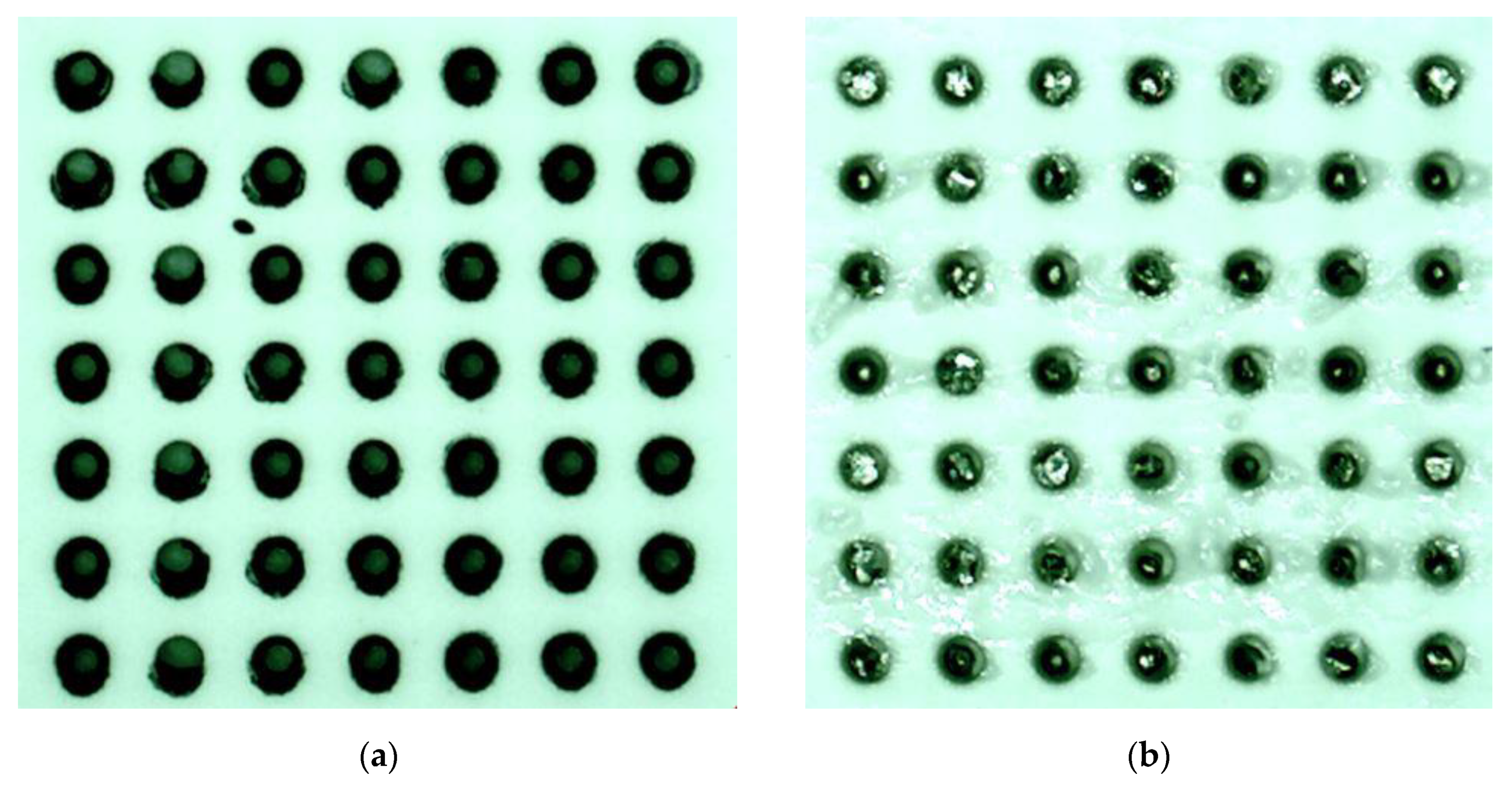
The different samples were visually inspected after stacking. After stacking agglomerations on the top surface were present on both agar-agar and gelatin, while the other samples remained clean. The carbon paste screen printing had an offset (<25 µm) which resulted in the smallest holes being only two-thirds filled. Additionally, the largest and the second-largest holes had an incomplete fill and had a rim of carbon paste covering the holes’ circumference across the whole tape height. This can be seen in Figure 4. Comparing against the same hole size for the gelatin sample in Figure 4, gelatin completely fills the holes, despite the excess on the top surface. Similar results were observed for the agar-agar and two HEC samples at all hole sizes.
The ease of filling using HEC 2 wt%, HEC 5 wt% as well as the agar-agar and gelatin was in contrast to the handling of the carbon paste, which required the production of a mask set, a screen fabrication and a screen printer in order to fill the holes and minimise residue between the layers. As is seen in Figure 4, some carbon paste was printed on the tape surface (as well as into the holes) forming a kind of “landing pad”. This inhibited the lamination in these areas. The two largest hole sizes were underfilled with the carbon paste. The high viscosity carbon paste passed through the holes in the screen-printing process. In order to increase fill, a second and possibly third screen-printing step should be considered. This would increase cost and time, and would only be considered if no other solution was possible.

3.2. Visual Inspection after Lamination

The two most interesting results were the no SVM case and the HEC 2 wt% case. Photographs of these two samples are presented below in Figure 5.
Comparing the samples before and after lamination, the holes of the HEC 2 wt% sample were well preserved, while the holes in the no SVM sample were reduced in size. The HEC 5 wt% and the gelatin sample also have preserved hole sizes while the agar-agar sample showed a lot of residue within the holes and on the surface.

3.2.1. Hole and Pitch Size and Shrinkage after Firing

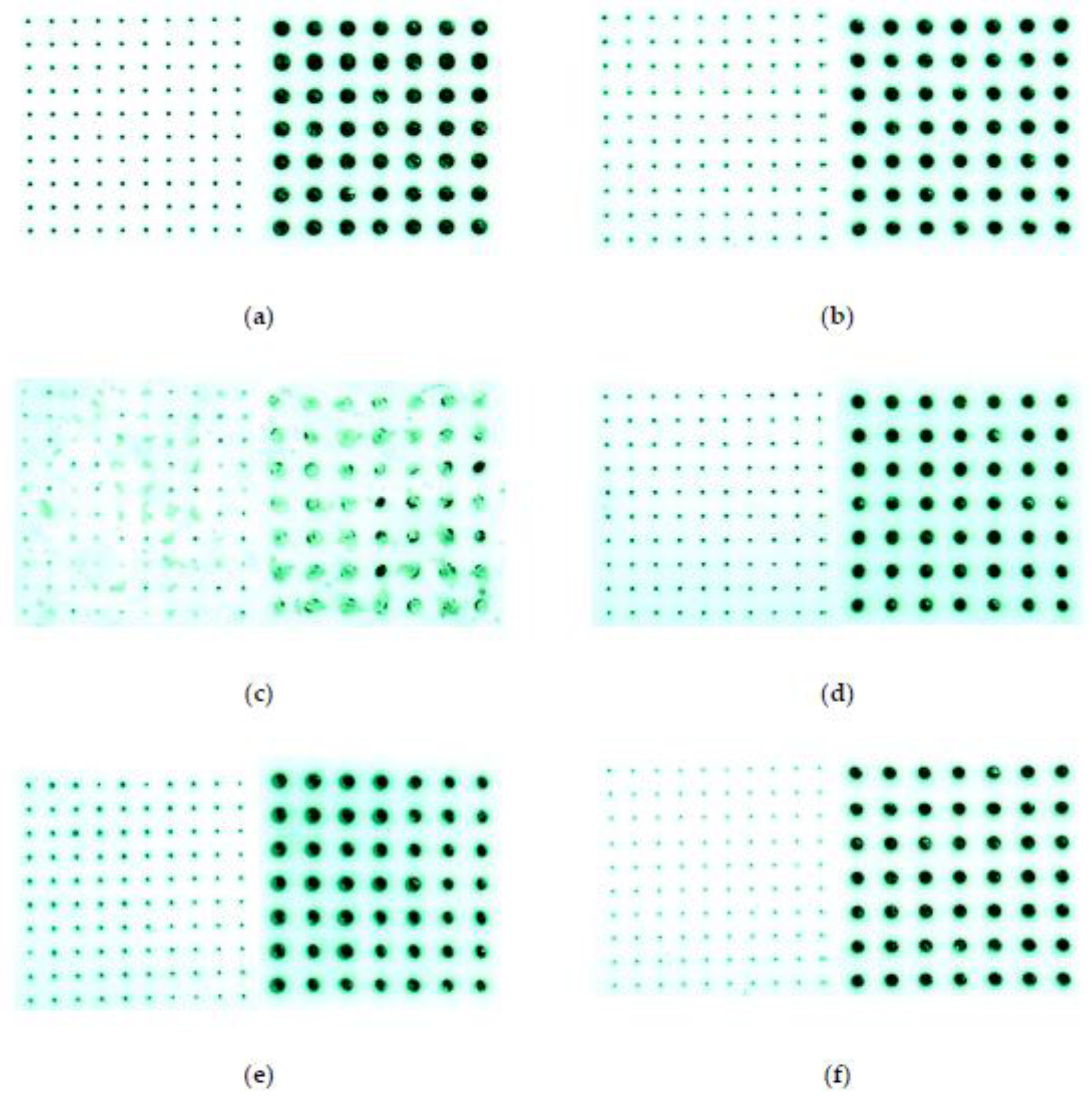
Images of the smallest and largest holes of the different samples are shown in Figure 6. The HEC 2 wt% sample has the least obstructed and best uniformity of the smallest holes. The HEC 5 wt%, gelatin and No SVM samples’ holes were smaller even though they have stayed circular and uniform—meaning that some degree of residue is present. The carbon paste sample shows holes with varying sizes (due to a varying fill ratio) and also a slight discoloration around the holes where the paste has been applied. For the agar-agar sample, the holes and the substrate surface had a large amount of residue present making the surface rough and, therefore, unacceptable.
It was expected that the Ferro A6M-E tape shrinks by 15.6% in the lateral direction, as given by the manufacturer for a normal lamination using 21 MPa pressure, a temperature of 70 °C for 10 min duration. Ferro has also shown that shrinkage may vary with pressure; a lower pressure gives higher shrinkage [35]. However, [35] used a fixed temperature of 70 °C and a higher pressure than used here. Thus, changes in shrinkage were expected due to both the lamination procedure and to the SVM used.
The resulting measurements of the four different hole sizes, as well as the pitch between holes, are presented in Table 1, except for the agar-agar sample which had residuals left in the holes.
The measured diameters for the pitch after laser cut out, and post-firing, in addition to the calculated shrinkage are presented in Table 1. For the pitch shrinkage, this value represents an overall shrinkage to be compared to the 15.6% given by the manufacturer. It varies slightly for the different SVMs ranging from 19% to 21%. The lowest shrinkage, 19%, was obtained for the no SVM sample and used as the reference value regarding the lamination parameters, which are lower than the manufacturer’s values. Use of SVMs increases the shrinkage slightly by one or two points. The overall shrinkage, taken as the largest diagonal hole to hole agrees with the pitch shrinkage value.
Looking at the hole diameters and their shrinkage values, large variations were apparent depending on the hole sizes. The HEC 2 wt% holes have the most uniform shape with a 2 to 3 µm standard deviation. The HEC 5 wt% also exhibit good hole uniformity. The gelatin and carbon paste samples exhibit large variations, 23 and 28 µm respectively, for various hole sizes, while the no SVM case has, together with the gelatin, a worst standard variation of 12 µm and 14 µm respectively, for the smallest holes. It can therefore be concluded that the gelatin is a poor SVM since it provides no improvement compared to the no SVM case. Shrinkage varies depending on the initial hole size, meaning that the smaller the hole, the greater the importance of shrinkage. The best overall results were obtained when using the HEC 2 wt% liquid as SVM. For the two largest holes, shrinkage was similar to the pitch value, which was considered as the design shrinkage value. Decreasing the hole size then increased the shrinkage giving a value of 56% for the smallest holes. As a result, features smaller than 200 µm, should be treated differently than the overall tape when preparing for manufacturing.
Regarding the protection of small holes (or other features) by the preservation of its shape during lamination, the HEC 2 wt% performed the best. However, further analysis of the interlayer lamination is required.

3.2.2. Lamination Evaluation

The lamination was evaluated by cross-sectioning the samples. Figure 7 shows the obtained micrographs. In all but the agar-agar case, excellent lamination over the non-holed surface was obtained. Figure 7c clearly shows that there was no lamination obtained between the layers for the agar-agar sample.
The cross-sections also allowed measurement of the shrinkage in the vertical direction. The z-direction shrinkage as provided by the manufacturer is 28 ± 3% when using a standard lamination which was used here as the reference lamination value. The lamination value of the samples was calculated by measuring the after stacking and vacuum treatment thickness’. Only one measurement was taken at one point in the cross-section, thus this value was used for indication purposes only.
The measurements are shown in, Table 2. For the samples where lamination was achieved, the z shrinkage varies from 27 to 33%-similar to that given by the manufacturer. Note that the before and after firing values were not taken at the same location; 33% can be considered as the default value for the no SVM and carbon paste since there was no AAL. However, where an adhesive was used, irrespective of type; HEC 2 wt%, HEC 5 wt% or gelatin, the z shrinkage was less pronounced.
Figure 8 shows the cross-section across a hole structure. This allowed for the measurement of any misalignment, which was 30–40 µm in the lateral direction. This misalignment was due to the alignment holes in the laser cut tapes being larger than intended due to an operator error during the laser-cutting step. More interesting was the small but evident gaps between the tapes around the holes of the carbon paste sample, as seen in Figure 8e. These gaps were a result of the screen-printed carbon paste around the hole orifices when filling the holes as reported earlier in this paper. The carbon paste is typically used to create empty structures, normally between layers, which was the result here. The agar-agar material shows some delamination as well as evidence of residue within the holes.
In conclusion, lower lamination parameters, i.e., 7 MPa, 5 min and 62 °C, work well for the Ferro A6M-E material. Different materials can be used to serve as AALs in the LTCC fabrication procedure, and the HEC 2 wt%, HEC 5 wt% and gelatin work well in this regard, while the agar-agar prevents good lamination. The carbon paste was not intended for this purpose and it is clear that when placed between layers it hinders the lamination in that very area. The no SVM case is also well laminated, considering the absence of an AAL and for the parameters set.

3.2.3. Thermogravimetric Analysis (TGA) Results

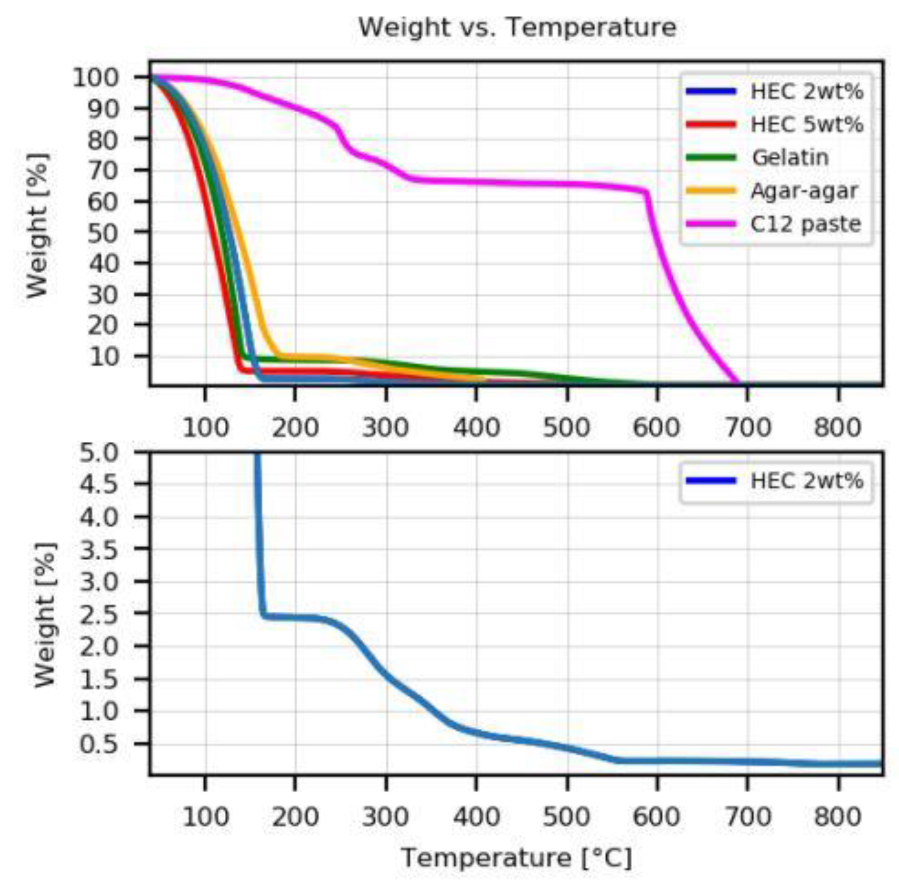
The decomposition traces for the five SVM’s are shown in Figure 9 and the decomposition temperatures given in Table 3. From all the SVM’s, the remaining residue was negligible above 700 °C due to the complete combustion of all material in the oxygen environment. The SVMs evaporated all of their liquid components by 250 °C and each had a multi-stepped decomposition profile—as evidenced in the carbon paste sample, indicating the presence of other solids. The total carbon content of the carbon paste sample was approximately 65%.
At the lamination temperature, i.e., 62 °C, all SVMs with the exception of the carbon paste had begun to lose weight. The remaining weight at this temperature is presented in Table 3. Fortunately, the weight loss is small enough in order for the SVM to fulfil its function.
Due to the high liquid fraction within the HEC 2 wt%, it experienced the greatest weight loss upon evaporation, thereby leaving the lowest solids content of all the SVMs for decomposition. This 2% solids content could reasonably be expected to experience full decomposition and combustion within the LTCC structure upon firing in the air furnace leaving no residue—making it the most suitable SVM. The TGA curve for the HEC 2 wt% at a weight-loss larger than 95% is presented in the lower graph of Figure 9, for better visibility.
Given these results, an intermittent outgassing plateau is not required for the proposed SVMs, except for the carbon paste, as was proposed in [24].

3.2.4. SEM-EDX Results

Residual analysis of the samples was performed in a scanning electronic microscope (SEM) with energy-dispersive X-ray spectroscopy (EDX) features. The EDX test was performed on the surface of each sample, in between the holes using 300 times magnification in order to capture any possible residuals remaining after the firing. A comparison between the different materials (except HEC 5 wt% due to lack of time) is presented in Figure 10. The atomic elements found in the different samples throughout the analysis were exactly the same, thus no residuals were present after firing supports the thermogravimetric analysis results showing that complete diffusion of the SVMs during the firing of the LTCC was obtained.
The atomic composition for the no SVM sample, i.e., for the Ferro A6M-E LTCC ceramic itself, is as follows; oxygen 65.89%, carbon 25.75%, silicon 5.46%, calcium 1.95%, aluminum 0.37%, natrium 0.35% and magnesium 0.22%.
SEM-EDX analysis was also performed on the material left in the agar-agar holes and on the sample’s surface. It was found that they have the same EDX-profile as for the ceramic material itself. It seems like the ceramic has burst open during firing when evacuating the SVM.

4. Discussion

An overview of the different results, as compared to the requirements listed in Section 1.2, is presented in Table 4. The HEC 2 wt% sample corresponds well to all requirements listed and performed the best when compared with the other materials. It is easy to use, preserves the shape of the holes on all layers, contributes to the adhesive-assisted lamination and results in an excellent intra-layer lamination. The HEC 2 wt% leaves no residues after firing and is not hazardous to health or the environment. For holes smaller than 200 µm, extra compensation for shrinkage should be used. The HEC 5 wt% also performed well, with the only difference compared to the HEC 2 wt%, being that the hole shrinkage for all the holes is larger. The agar-agar is easy to apply, cheap and non-hazardous but leaves burst ceramics in the holes and on the surface of the substrate and inhibits lamination. Gelatin is easy to apply, cheap and non-hazardous, however, there is no significant benefit to using this in comparison with the no SVM sample. The carbon paste is not adapted for this special case; it should be used to create channels, membranes, suspended bridges or even moving parts as was presented in [19,25]. The no SVM case is possible to use, however, the holes were more impacted during the lamination than for the HEC 2 wt% and HEC 5 wt%. From an interlayer lamination point of view, excellent results were obtained for all but the agar-agar and the carbon paste materials. In all of the tested cases, the given lateral shrinkage is higher than proposed by the tape manufacturer. The lower pressure and temperature were the main reasons for this. The no SVM sample shows a 19% shrinkage, however, the SVM material adds one to two points to this value. The vertical shrinkage varies depending on which material is used. The obtained values range from 27% to 33% where the latter is recorded for the no SVM as well as for the carbon paste case, i.e., for the two samples where no AAL was used. When AAL was used, values of 27 to 30% were recorded, which were similar to the 28% provided by the fabricant, although for different lamination parameters.
This research will be continued for the same tape material to include a partly metallized, partly holed layer as proposed in [31]. It is possible that the HEC 2 wt% has a negative impact on the inter-layer lamination when metal is present, so this needs to be investigated. Additionally, this body of work used only three layers within the prototypes in order to reduce cost. A regular LTCC circuit is often made up of 10 or more layers, so further work is needed to reflect this.
In addition, any decreases in relative permittivity for the material has not been measured. Test samples with different hole sizes and pitch should first be electromagnetically simulated, fabricated and then tested to validate the performance. Given equation 1 in [30], it is expected that the work could lower this value from 5.7 to approximately 4.7 for the 220 µm holes and the 451 µm pitch achieved with the HEC 2 wt%.
Finally, to further improve the shape of the grooves in the structure as presented in [15] the HEC 2 wt% combined with fugitive tape may provide the solution—by using fugitive tape in the vapor chamber combined with HEC 2 wt% in the grooves on the layers placed underneath and on top of the vapor chamber.

5. Conclusions

This work has provided a solution to the creation of a hole pattern covering a large surface of each LTCC tape in a multilayer configuration. This kind of structure could be useful when a modified, lowered, relative permittivity is needed in an LTCC structure or for special structures such as substrate integrated circuits with a waveguiding functionality.
The best results have been obtained when using HEC 2 wt%. This material has two functions; first, it works as an adhesive to help the layers merge, i.e. adhesive-assisted lamination, requiring low lamination parameters and secondly, it functions as protection when filled into the hole structures to help keep their shape during lamination. Several advantages can be given to this HEC 2 wt% material; it is cheap, commercially available, easily mixed to any weight percentage, it is very easy to apply and can be spread onto the surface of each tape while filling the hole structures at the same time. HEC 2wt% is stable over time, it is also non-hazardous to health and environment and requires no specialized equipment except for a balance when preparing it. Additionally, it has shown no negative effects on the tape and leaves no residues after firing.
This work tested only circular holes, sized from 158 µm to 268 µm with a pitch of 573 µm in the green state and used one LTCC material, the commercially available Ferro A6M-E 5 mil tape. The study has demonstrated that compared to the no SVM case, especially the smallest holes were better protected by the use of the SVM material. The result after firing hole sizes for the HEC 2 wt% sample were 69, 116, 162 and 204 µm with preserved shape and excellent uniformity, thus responding perfectly to our requirements.
Future work should include other materials, shapes and also metallized layers.

Author Contributions

Conceptualization, D.Z. and F.G.; methodology, C.K.; validation, C.K. and M.S.; investigation, C.K. and P.D.; writing—original draft preparation, C.K.; writing—review and editing, C.K., D.Z., F.G., M.S. and P.D.; project administration, D.Z.; resources, C.K. and P.D.; funding acquisition, C.K. and D.Z. All authors have read and agreed to the published version of the manuscript.

Funding

This research was funded by The Royal Society, grant number IES\R1\191236 and The APC was funded by MDPI. The laser equipment was funded by Brest Metropole “Fonds de Concours à la Recherche”, by the Finistère department council’s program “Aide aux Programmes de Recherche Emergants” and by Carnot Research funds. The laser equipment used in this work was co-funded by Brest Metropole FCR program, the department of Finistère in their AAPR program, and the Carnot program.

Acknowledgments

The authors would like to thank two student groups for preparing this work and proposing materials eligible for testing. Julian Kopp and Ali Alkhathami worked on a bibliographical survey and Joanne Khater, Romain Tessier and Mohammed Ez-Zerraq performed preliminary testing of SVM materials. We would also like to thank Philippe Elies at Plateforme d’Imagerie et de Mesures en Microscopie—UFR des Sciences and Techniques at Université de Bretagne Occidentale for performing the SEM-EDX analysis and Bronagh Miller for letting Douglas perform the TGA.

Conflicts of Interest

The authors declare no conflict of interest. The funders had no role in the design of the study; in the collection, analyses, or interpretation of data; in the writing of the manuscript; or in the decision to publish the results.

References

  1. Gyurk, W.J. Methods for Manufacturing Multilayered Ceramic Bodies. U.S. Patent 3,192,086, 29 June 1965. [Google Scholar]
  2. Nakayama, T. Low-Fire Green Ceramic Articles and Slip Compositions for Producing Same. U.S. Patent 4,010,133, 1 March 1977. [Google Scholar]
  3. Kumar, A.H.; McMillan, P.W.; Tummala, R.R. Glass-Ceramc Structures and Sintered Multilayer Substrates Thereof with Circuit Patterns of Gold, Silver or Copper. U.S. Patent 4,301,324, 17 November 1981. [Google Scholar]
  4. KOA LTCC Substrates. Available online: http://www.koaspeer.com/products/ltcc-substrates-others/ltcc-substrates/ (accessed on 28 September 2020).
  5. TDK. Vol.3 TDK’s LTCC AiP Technology Supports 5G Communications. Available online: https://www.tdk.com/tech-mag/front_line/003 (accessed on 28 September 2020).
  6. KYOCERA. Material Properties|Ceramic Packages|Products|KYOCERA. Available online: https://global.kyocera.com/prdct/semicon/material/ (accessed on 28 September 2020).
  7. DuPont. Low Temperature Co-Fired Ceramic Material Systems. Available online: https://www.dupont.com/electronic-materials/low-temperature-co-fire-ceramic-materials.html (accessed on 28 September 2020).
  8. Ferro Electronic Materials. Available online: https://www.ferro.com/products/product-category/electronic-materials (accessed on 28 September 2020).
  9. Lee, Y.C.; Kim, T.W.; Ariffin, A.B.; Myoung, N.-G. 60-GHz amplitude shift-keying receiver LTCC system-on-package module. Microw. Opt. Technol. Lett. 2011, 53, 758–761. [Google Scholar] [CrossRef]
  10. Fournier, Y. 3D Structuration Techniques of LTCC for Microsystems Applications. Ph.D. Thesis, Ecole Polytechnique Fédérale de Lausanne, Lausanne, Switzerland, 2010. [Google Scholar]
  11. Malecha, K.; Golonka, L.J. Three-dimensional structuration of zero-shrinkage LTCC ceramics for microfluidic applications. Microelectron. Reliab. 2009, 49, 585–591. [Google Scholar] [CrossRef]
  12. Arenas Buendia, C. Enhanced Fluid Characterization in the Millimeter-Wave Band Using Gap Waveguide Technology. Ph.D. Thesis, Universitat Politècnica de València, Valencia, Spain, 2016. [Google Scholar]
  13. Jones, W.K.; Yanqing, L.; Mingcong, G. Micro heat pipes in low temperature cofire ceramic (LTCC) substrates. IEEE Trans. Comp. Packag. Technol. 2003, 26, 110–115. [Google Scholar] [CrossRef]
  14. Shi, P.Z.; Chua, K.M.; Wong, S.C.K.; Tan, Y.M. Design and performance optimization of miniature heat pipes in LTCC. J. Phys. Conf. Ser. 2006, 34, 142–147. [Google Scholar] [CrossRef]
  15. Tlili, M.; Sinou, M.; Karnfelt, C.; Bourreau, D.; Peden, A. Micro Heat Pipe Design and Fabrication on LTCC. In Proceedings of the 2018 7th Electronic System-Integration Technology Conference (ESTC), Dresden, Germany, 18–21 September 2018; IEEE: Dresden, Germany, 2018; pp. 1–3. [Google Scholar]
  16. Malecha, K.; Jurków, D.; Golonka, L.J. Comparison of solvent and sacrificial volume-material-based lamination processes of low-temperature co-fired ceramics tapes. J. Micromech. Microeng. 2009, 19, 065022. [Google Scholar] [CrossRef]
  17. Malecha, K. Fabrication of cavities in low loss LTCC materials for microwave applications. J. Micromech. Microeng. 2012, 22, 125004. [Google Scholar] [CrossRef]
  18. Toskov, S.; Krcic, N.; Radosavljevic, G. LTCC lamination process using PMMA fugitive material. In Proceedings of the 2014 37th International Spring Seminar on Electronics Technology, Dresden, Germany, 7–11 May 2014; IEEE: Piscataway, NJ, USA, 2014; pp. 21–26. [Google Scholar]
  19. Peterson, K.A.; Patel, K.D.; Ho, C.K.; Rohde, S.B.; Nordquist, C.D.; Walker, C.A.; Wroblewski, B.D.; Okandan, M. Novel Microsystem Applications with New Techniques in Low-Temperature Co-Fired Ceramics. Int. J. Appl. Ceram. Technol. 2005, 2, 345–363. [Google Scholar] [CrossRef]
  20. Maeder, T.; Jacq, C.; Fournier, Y.; Hraiz, W.; Ryser, P. Structuration of zero-shrinkage LTCC using mineral sacrificial materials. In Proceedings of the 2009 European Microelectronics and Packaging Conference, Rimini, Italy, 16–18 June 2009; pp. 1–6. [Google Scholar]
  21. Tick, T.; Jäntti, J.; Henry, M.; Free, C.; Jantunen, H. LTCC integrated air-filled waveguides for G-band applications. Microw. Opt. Technol. Lett. 2009, 51, 176–178. [Google Scholar] [CrossRef]
  22. Lahti, M.; Kautio, K.; Karioja, P. Integrated LTCC Modules by Laminating and Co-firing Tapes Directly on Heat Sink. In Proceedings of the 2006 European Conference on Wireless Technologies, Manchester, UK, 10–12 September 2006; IEEE: Piscataway, NJ, USA, 2006; pp. 372–375. [Google Scholar]
  23. Horváth, E.; Harsányi, G. Optimization of fluidic microchannel manufacturing processes in low temperature co-fired ceramic substrates. Period. Polytech. Electr. Eng. 2010, 54, 79. [Google Scholar] [CrossRef] [Green Version]
  24. Hrovat, M.; Belavic, D.; Cilensek, J.; Drnovsek, S.; Holc, J.; Jerlah, M. Investigation of sacrificial layers for 3D LTCC structures and some preliminary results. In Proceedings of the 2009 32nd International Spring Seminar on Electronics Technology, Brno, Czech Republic, 13–17 May 2009; IEEE: Piscataway, NJ, USA, 2009; pp. 1–6. [Google Scholar]
  25. Birol, H.; Maeder, T.; Ryser, P. Application of graphite-based sacrificial layers for fabrication of LTCC (low temperature co-fired ceramic) membranes and micro-channels. J. Micromech. Microeng. 2007, 17, 50–60. [Google Scholar] [CrossRef]
  26. Malecha, K.; Maeder, T.; Jacq, C.; Ryser, P. Structuration of the low temperature co-fired ceramics (LTCC) using novel sacrificial graphite paste with PVA–propylene glycol–glycerol–water vehicle. Microelectron. Reliab. 2011, 51, 805–811. [Google Scholar] [CrossRef] [Green Version]
  27. Jurkow, D.; Roguszczak, H.; Golonka, L. Cold chemical lamination of ceramic green tapes. J. Eur. Ceram. Soc. 2009, 29, 703–709. [Google Scholar] [CrossRef]
  28. Smetana, W.; Balluch, B.; Stangl, G.; Lüftl, S.; Seidler, S. Processing procedures for the realization of fine structured channel arrays and bridging elements by LTCC-Technology. Microelectron. Reliab. 2009, 49, 592–599. [Google Scholar] [CrossRef]
  29. Khoong, L.E.; Tan, Y.M.; Lam, Y.C. Overview on fabrication of three-dimensional structures in multi-layer ceramic substrate. J. Eur. Ceram. Soc. 2010, 30, 1973–1987. [Google Scholar] [CrossRef]
  30. Schuler, K.; Venot, Y.; Wiesbeck, W. Innovative Material Modulation for Multilayer LTCC Antenna Design at 76.5 GHz in Radar and Communication Applications. In Proceedings of the 33rd European Microwave Conference, Munich, Germany, 7–9 October 2003; IEEE: Piscataway, NJ, USA, 2003; pp. 707–710. [Google Scholar]
  31. Ke, W.; Desiandes, D.; Cassivi, Y. The substrate integrated circuits—A new concept for high-frequency electronics and optoelectronics. In Proceedings of the 6th International Conference on Telecommunications in Modern Satellite, Cable and Broadcasting Service, Nis, Yugoslavia, 1–3 October 2003; TELSIKS 2003. IEEE: Piscataway, NJ, USA, 2003; Volume 1, pp. P-III–P-X. [Google Scholar]
  32. Tlili, M.; Kärnfelt, C.; Sinou, M.; Peden, A. Cold Chemical Lamination Tests of Grooved Internal Cavities in LTCC for Thermal Management. In Proceedings of the IMAPS From Nano to Macro Power Electronics and Packaging European Workshop, Tours, France, 28 November 2019; p. 6. [Google Scholar]
  33. Carbon Paste—C12 Advanced Technologies. Available online: http://c12materials.com/carbonpaste.html (accessed on 28 September 2020).
  34. Cellulose hydroxyéthylique MSDS—822068—Merck. Available online: https://www.merckmillipore.com/FR/fr/product/msds/MDA_CHEM-822068?ReferrerURL=https%3A%2F%2Fduckduckgo.com%2F (accessed on 16 October 2020).
  35. LTCC. Material System|A6M-E LTCC Tape-High Frequency Applications. Available online: https://www.ferro.com/products/product-category/electronic-materials/ltcc-material-systems/low-temperature-co-fired-_ltcc_--materials/a6m-e-ltcc-material-systems-for-high-frequency-applications (accessed on 6 October 2020).
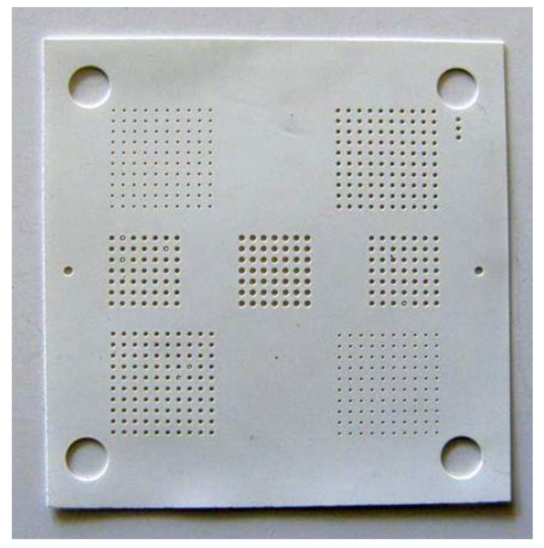
Figure 1. One Ferro A6M-E tape layer where hole matrixes of different diameter are placed. The top left and the lower right matrixes are made up of 116 µm holes, the top right and the lower left matrixes of 174 µm holes, the middle line left and right matrixes are made up of 232 µm holes and the middle matrix is made up of 291 µm holes all with a pitch of 573 µm. The dimensions are given before firing intended for a 15.6% shrinkage.
Electronics 09 02168 g001
Figure 2. Stacking of three layers onto an alignment fixture, in this case, using hydroxyethyl cellulose (HEC) 2 wt%. The surface of the top layer is shiny because of the presence of the HEC 2 wt% material.
Electronics 09 02168 g002
Figure 3. Firing profile for the Ferro A6M-E tape material without forced cooling.
Electronics 09 02168 g003
Figure 4. The carbon paste does not fill the 232 µm and 291 µm holes, however, the gelatin, the agar-agar and the two HECs fill all holes completely: (a) carbon paste, 232 µm holes, (b) gelatin, 232 µm holes.
Electronics 09 02168 g004
Figure 5. Two of the samples after lamination: (a) the one with HEC 2 wt% and (b) the no sacrificial volume material (SVM) sample.
Electronics 09 02168 g005
Figure 6. Close-up on the smallest and largest matrixes for each sample, after firing: (a) HEC 2 wt%, (b) HEC 5 wt%, (c) agar-agar, (d) gelatin, (e) carbon paste and (f) no SVM.
Electronics 09 02168 g006
Figure 7. Cross-sections of the samples, after firing: (a) HEC 2 wt%, (b) HEC 5 wt%, (c) agar-agar, (d) gelatin, (e) carbon paste, and (f) no SVM. For all samples, except the agar-agar sample, lamination between layers is excellent.
Electronics 09 02168 g007
Figure 8. Cross-sections of the samples, after firing: (a) HEC 2 wt% hole structure, (b) HEC 5 wt% hole structure, (c) agar-agar hole structure (d) gelatin hole structure, (e) carbon paste hole structure and (f) no SVM hole structure. The hole structures as presented in these figures are not of the same hole size.
Electronics 09 02168 g008
Figure 9. Thermogravimetric analysis (TGA) decomposition traces for the five tested SVM materials in the upper graph and the HEC 2 wt% for weight below 5% in the lower graph.
Electronics 09 02168 g009
Figure 10. Energy-dispersive X-ray spectroscopy (EDX) spectrum for the different materials (except HEC 5 wt%). The plot colors indicate the materials as follows; HEC 2 wt% (black), agar-agar (red), gelatin (light blue), carbon paste (green) and no SVM (blue).
Electronics 09 02168 g010
Table 1. Hole and pitch dimensions (mean value and standard deviation rounded to nearest µm) after firing and calculated shrinkage for the different test samples.
Cut Size [µm]HEC 2 wt%
[µm]→[%]
HEC 5 wt%
[µm]→[%]
Agar-Agar
[µm]→[%]
Gelatin
[µm]→[%]
Carbon Paste
[µm]→[%]
No SVM
[µm]→[%]
Ф 2 = 158 69 ± 3→56 172 ± 4→54-58 ± 14→6374 ± 4→5354 ± 12→66
Ф 2 = 186 116 ± 2→37111 ± 2→40-80 ± 14→57110 ± 28→4188 ± 5→53
Ф 2 = 220 162 ±3→26162 ± 6→26-128 ± 23→42173 ± 7→21136 ± 4→38
Ф 2 = 268 204 ± 2→24199 ± 6→26-179 ± 7→33207 ± 6→23174 ± 7→35
Δ 3 = 573451→21451→21452→21454→21461→20462→19
1 Shrinkage, calculated using the difference from the laser cut green tape value to the resulting fired value, e.g., (1 − (69/158)) × 100 for the smallest hole size of the HEC 2 wt% sample, 2 Ф = hole diameter, 3 Δ = hole to hole distance (pitch).
Table 2. Vertical shrinkage (final value after firing compared to thickness after stacking of three layers of Ferro A6M-E 5 mil tape, i.e., 381 µm.
HEC 2 wt%HEC 5 wt%Agar-AgarGelatinCarbon Paste No SVM
Measured thickness after firing277 µm274 µm80 µm/layer265 µm257 µm255 µm
Calculated z shrinkage27%28%37%/layer30%33%33%
Table 3. Liquid content, bulk decomposition temperature and remaining weight at 62 °C for the SVM samples.
HEC 2 wt%HEC 5 wt%Agar-AgarGelatinCarbon Paste
Liquid content [%]97.5994.9890.3691.376.83
Bulk decomposition temperature [°C]249240244283590
Remaining weight at 62 °C [%]96.3493.2996.7595.5999.87
Table 4. Comparison of results as compared to the initial requirements.
HEC 2 wt%HEC 5 wt%Agar-AgarGelatinCarbon PasteNo SVM
Ease of useExcellentExcellentExcellentExcellentNo—requires screen-printingExcellent
Filling of multiple holes over a large areaExcellentExcellentExcellentExcellentPoor for larger holesNA
Keeps its shape during laminationYes, ±2–3 µm variation and 24–56% shrinkageYes, ±2–6 µm variation and 26–54% shrinkageNot evaluatedNo, ±7–23 µm variation and 33–63% shrinkageNo, ±4–28 µm variation and 23–53% shrinkageNo, ±4–12 µm variation and 35–66% shrinkage
Lamination qualityExcellentExcellentNo laminationExcellentExcellent unless for “Landing pads” that inhibits laminationExcellent
Negative effectsNoNoYes, bursts during firing result in a rough substrate surfaceNoYes, coloring around hole orifices No
Residues after firingNoNoNo, but ceramic outbursts in holes and on a top surfaceNo, but ceramic outbursts in few holes NoNA
Hazardous to health or environmentNoNoNo, eatableNo, eatableYesNA
Price 1 and availability25 €/100 gr25 €/100 gr~23 €/500 gr~2 €/100 gr545 $/50 gr0 €
1 The prices for agar-agar and gelatin are taken from web merchants’ sites. The HEC and the carbon paste prices are the prices paid by our laboratory.
Publisher’s Note: MDPI stays neutral with regard to jurisdictional claims in published maps and institutional affiliations.