Article

A Compact C-Band Bandpass Filter with an Adjustable Dual-Band Suitable for Satellite Communication Systems

1
School of Engineering, Macquarie University, Sydney, NSW 2109, Australia
2
Young Researchers and Elite Club, Kermanshah Branch, Islamic Azad University, Kermanshah 6718997551, Iran
3
Research Institute for Microwave and Millimeter-Wave Studies, National University of Sciences and Technology, Islamabad 44000, Pakistan
4
The Institute of Electronics and Telecommunications of Rennes (IETR), University of Rennes 1, 35000 Rennes, France
5
The Edward S. Rogers, Sr. Department of Electrical and Computer Engineering, University of Toronto, Toronto, ON M5S 3G4, Canada
6
School of Electronics, Electrical Engineering, and Computer Science, Queen’s University, Belfast BT9 5BN, UK
7
School of Electronics Engineering, Kyungpook National University, Daegu 41566, Korea
*
Author to whom correspondence should be addressed.
Electronics 2020, 9(7), 1088; https://doi.org/10.3390/electronics9071088
Submission received: 30 May 2020 / Revised: 21 June 2020 / Accepted: 25 June 2020 / Published: 3 July 2020
(This article belongs to the Section Microwave and Wireless Communications)

Abstract

:
A narrowband dual-band bandpass filter (BPF) with independently tunable passbands is presented through a systematic design approach. A size-efficient coupling system is proposed with the capability of being integrated with additional resonators without increasing the size of the circuit. Two flag-shaped resonators along with two stepped-impedance resonators are integrated with the coupling system to firstly enhance the quality response of the filter, and secondly to add an independent adjustability feature to the filter. The dual passband of the filter is centered at 4.42 GHz and 7.2 GHz, respectively, with narrow passbands of 2.12% and 1.15%. The lower and upper passbands can be swept independently over 600 MHz and 1000 MHz by changing only one parameter of the filter without any destructive effects on the frequency response. According to United States frequency allocations, the first passband is convenient for mobile communications and the second passband can be used for satellite communications. The filter has very good in- and out-of-band performance with very small passband insertion losses of 0.5 dB and 0.86 dB as well as a relatively strong stopband attenuation of 30 dB and 25 dB, respectively, for the case of lower and upper bands. To verify the proposed approach, a prototype of the filter is fabricated and measured showing a good agreement between numerically calculated and measured results.

1. Introduction

Microstrip technology has been widely used in modern communication systems since it is a mature and highly reliable technology for microwave- and millimeter-wave applications [1,2,3,4,5,6,7,8,9,10,11]. In particular, multiband bandpass filters (BPFs) have been utilized in wireless communication transceivers to separate frequency spectrum in different bands. The C-band covers 4 GHz to 8 GHz in the microwave range used for weather radar systems and mobile and satellite communications (Satcom). In relation to satellite communication systems, the design of microwave filters has challenges associated to several factors, which include the spectrum scarcity and host environment. In order to satisfy individual filters’ requirements, conflicting solutions or custom technologies might be necessary, which result in a trade-off at component and system level [12]. Although distributed filters composed of many resonators can be a desired solution to satisfy the satellite communication requirements, such as high selectivity and low dissipation loss, such configurations lead to a circuit size with dimensions of several wavelengths, making the microwave front-end filters one of the bulkiest elements in the RF payload. As the mass and size of the on-board devices have a significant effect on the cost, reducing the footprint without compromising the filter performance becomes an important priority. Hence, the satellite communications industry has created a demand for low-mass narrowband low-loss filters with high selectivity [13,14,15]. As a result, affordability and compactness have become two critical requirements of microwave filters and other electromagnetic components used in the upcoming new generation of low-cost Satcom systems, where satellite communication-on-the-move will become a part of everyday life [12,13,14,15,16,17,18,19].
Hence, high-performance filters with a compact size and low-cost manufacturing are in high demand for such applications. Multiband BPFs have a particular place in communication receivers due to their properties of high insertion loss (IL) in rejection area, tunable response and sharp transition band. According to the recent literature, different techniques were suggested for designing BPFs, such as balanced BPFs [20,21,22,23,24], multilayer structures [25,26], balun BPFs [27], substrate integrated waveguide (SIW) technology [28,29], fractal configurations [30,31] and coupled resonator circuits (CRCs) [32,33,34,35,36,37,38,39,40,41,42,43,44,45]. In [35], a BPF was designed using coupled feed lines and compact main resonators. It had a short transition band, but the stopband was narrow. A similar coupling system was used along with some bended stubs to create a bandpass response through a compact filter design with 10 dB attenuation at the stopband in [36]. In [37], a dual-band BPF was developed using an improved stepped-impedance resonator, which showed a good suppression level due to several transmission zeros in the stopbands at a price of larger size. A simple configuration of BPF was implemented based on the coupled geometry in [38]. Although the intruder signals were deactivated under a desirable level, the circuit size was relatively large. Another BPF was realized based on a coupled topology in [39], in which the isolation between the passbands was only 17 dB. A more complex coupling system was presented in [41] using ring resonators that created high insertion losses in passbands with weak isolation between the bands. Modal analysis is another approach used to predict the location of transmission zeros, which can be adopted to realize a dual-band bandpass filter in [42]. The BPFs reported in [43] were implemented using the open/short stubs coupled with quarter-wave lines. These BPFs provided an acceptable attenuation level between the passbands; however, they were not size-efficient. Using the interdigital geometries, dual-band BPFs were fabricated in [44]. In these circuits, the common role of the fundamental resonators was to provide a dual-band performance and a compact size; however, the design approach was complex. In [45], the stepped-impedance stubs were coupled together to create a single and a dual-band BPF, resonating at 2.5 GHz and 3.5 GHz. These topologies suppressed the unwanted bands up to the 3rd harmonics; however, the attenuation in the stopbands was suboptimal. In a different design technique, artificial-intelligence-based approaches, such as particle swarm optimization, neural networks and ant colony, have recently been used to design microstrip filters as well as other microwave and electromagnetic components [46,47,48,49,50,51,52,53]. A simple topology of a dual-band BPF using a hybrid structure was developed in [54], where the passbands could separately be shifted at a price of increased passband insertion loss. In [27], a wideband balun BPF was designed using microstrip-to-slot line transition structures and some stub-loaded resonators. To realize a tunable dual-band BPF in [55], a loop structure coupled with bended stubs was loaded by square and T-shaped stubs. It could also be used in LPFs for extending the stopband [56,57,58,59]. Various design approaches for dual-band BPFs have been reported in the open literature. Most of them, however, focused on one or some critical properties at the price of other critical aspects.
In this paper, a straightforward yet systematic design approach which can sufficiently address all (or most of the) critical properties required for narrowband dual-band BPFs is presented. The proposed dual-band BPF provides properties of very good inter-band isolation level, strong attenuation in the stopband and low fabrication cost in a compact size. It can also provide fully tunable passbands, which can be independently adjusted by only one parameter, reducing the complexity of re-tuning the proposed filter for other possible applications.

2. Design Procedure

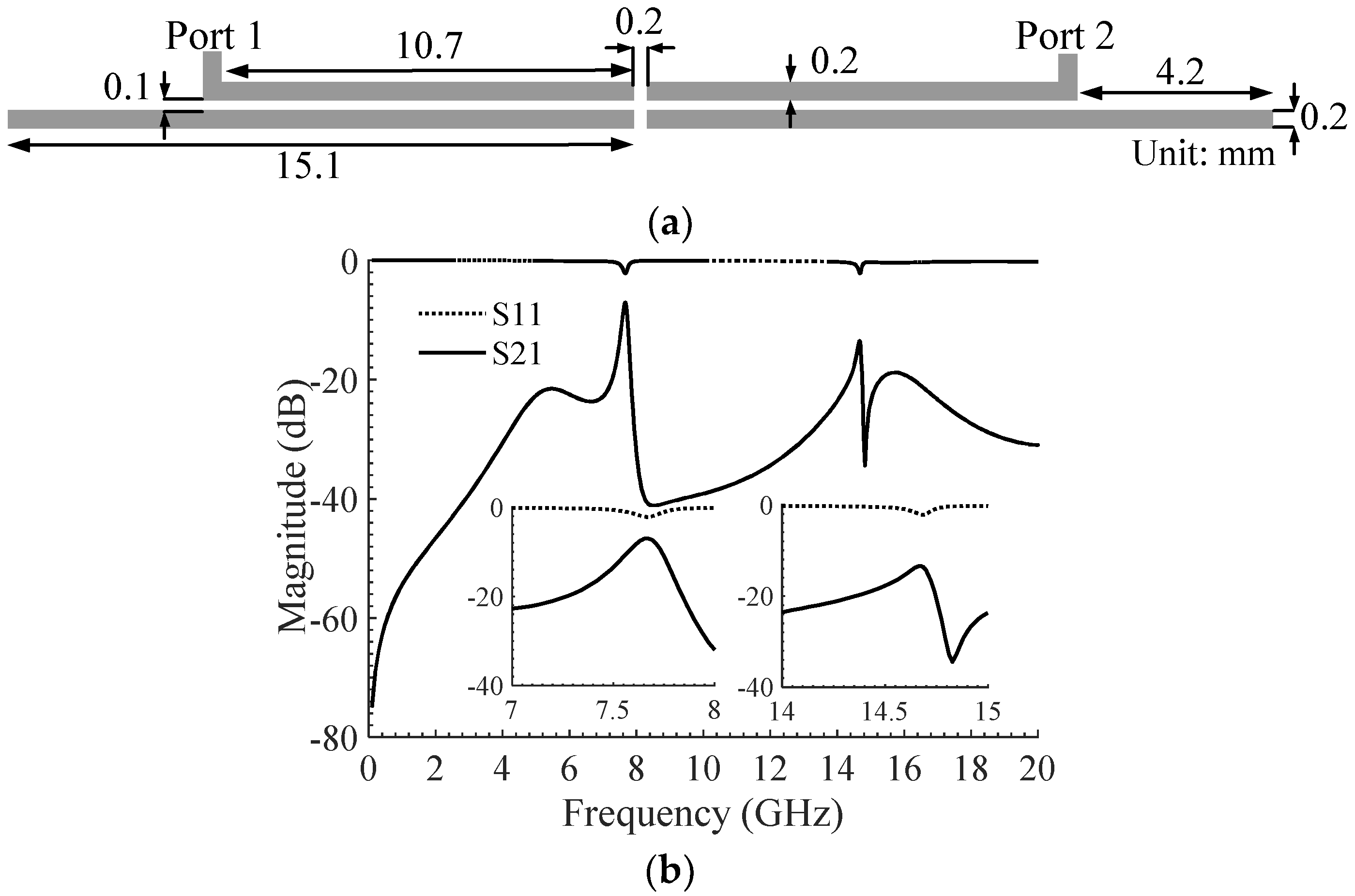
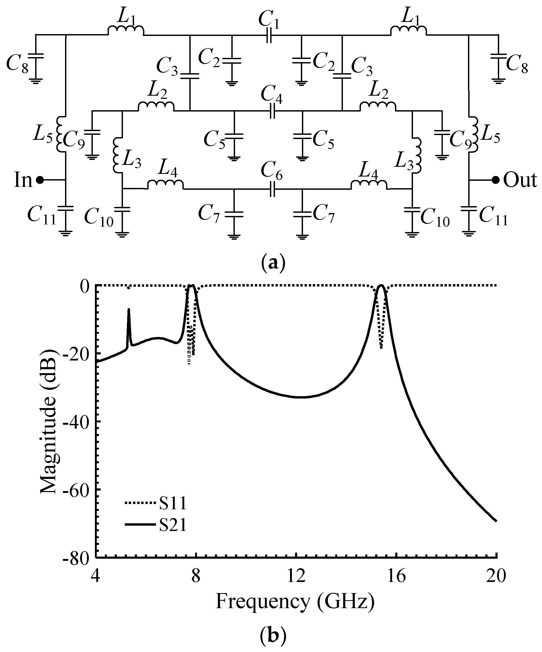
2.1. Proposed Coupling System

The conventional approach to creating a bandpass response is the use of capacitive gaps in the microstrip filters. However, the quality of the passband response can be significantly improved using multiple coupled transmission lines with different electrical lengths and capacitance gaps, leading to some traditional bandpass filters such as end-coupled, comb-line and hairpin-line BP filters [31,60]. Despite their straightforward design approaches, their dimensions are undesirably large due to the large number of coupled lines required for a passband with relatively small insertion loss. In this paper, a new coupling system inspired by the end-coupled lines is proposed, and a systematic miniaturization procedure is presented, which can be used for dual-band bandpass filters with independent passband adjustability. The advantage of the proposed method is that, unlike the abovementioned methods, only one end-coupled structure is required, contributing to a compact configuration.
Figure 1a shows a layout of one end-coupled transmission line to create a transmission pole at 7.66 GHz as shown in Figure 1b. The length of the coupled lines in this structure is close to half a guided wavelength at the first resonant frequency, which is inspired by the conventional end-coupled, half-wavelength resonator filters where a weak capacitive coupling is created through the gap between the two adjacent open ends. However, the conventional end-coupled filters are relatively large, due to the end to end orientation of the coupled lines [60]. To reduce the circuit size, the end-coupled lines are bent as shown in Figure 2a, resulting in a dual-band performance as depicted in Figure 2b. It needs to be mentioned that the effective length of coupled lines before and after bending remains almost same, and hence, the locations of the transmission poles remain almost unaffected by bending the coupled lines.
In order to further investigate the frequency behavior of the proposed structure and predict and control the resonant frequencies, an equivalent lumped circuit model can be extracted for the structure. The use of lumped-element circuit (LC) models for analyzing microwave filters’ behavior is a well-known approach and explained in [6,56,61,62]. The effect of the bends on the frequency response of the coupling system can be modeled by six capacitors (Cbend) as illustrated in a simplified lumped-element circuit (LC) model shown in Figure 3a. In the LC circuit, C1, C3, C4 and C6 denote the gap capacitances. C2, C5, C7 and C11 describe the capacitances of the open-end stubs. The inductances of transmission lines are also modeled by L1, L2, L3, L4 and L5, and the bending capacitances are denoted by C8, C9 and C10. The values of the lumped elements are obtained using the procedure outlined in [53,54], and calculated as follows: C1 = 0.107 pF, C2 = 0.73 pF, C3 = 0.3 pF, C4 = 0.05 pF, C5 = 1.289 pF, C6 = 0.045 pF, C7 = 7 pF, C8 = 0.535 pF, C9 = 7 pF, C10 = 5 pF, C11 = 0.65 pF, L1 = 0.4 nH, L2 = 0.34 nH, L3 = 0.5 nH, L4 = 0.435 nH and L5 = 0.75 nH. It can be seen from Figure 3b that introducing the bending capacitors improves the passband response, reducing the passband insertion loss from 7.05 to 0.66 dB. The first and second resonant frequencies of the filter shown in Figure 3b can be calculated by equating the input impedance of the equivalent circuit model to zero as shown in (1). As a result, the equations of resonances are obtained as (2) and (3).
( 1 + S 2 ( C 7 L 2 + C 3 C 7 + C 3 C 6 ) + S 4 C 3 C 6 C 7 L 2 + S 2 L 1 ( C 7 + C 6 + ( 1 + S 2 ( C 7 L 2 + C 3 C 7 + C 3 C 6 ) + S 4 C 3 C 6 C 7 L 2 ) C 2 ) + S 4 C 7 C 6 L 1 L 2 ) = 0
f 01 = 1 2 π | ( L 1 ( L 1 A 2 C 2 2 + 2 L 1 A C 2 C 6 + 2 L 1 A C 2 C 7 4 L 2 A C 6 C 7 + L 1 C 6 2 + 2 L 1 C 6 C 7 + L 1 C 7 2 ) ) + C 6   L 1 + C 7   L 1 + A C 2 L 1 2 C 6 C 7 L 1 L 2 | ,
f 02 = 1 2 π | ( L 1 ( L 1 A 2 C 2 2 + 2 L 1 A C 2 C 6 + 2 L 1 A C 2 C 7 4 L 2 A C 6 C 7 + L 1 C 6 2 + 2 L 1 C 6 C 7 + L 1 C 7 2 ) ) + C 6   L 1 + C 7   L 1 + A C 2 L 1 2 C 6 C 7 L 1 L 2 | ,
where
A = C 6 2 C 3 2 + 2 C 3 2 C 7 C 6 + C 3 2 C 7 2 2 C 3 C 6 C 7 L 2 + 2 C 3 C 7 2 L 2 + L 2 2 C 7 2 + C 3 C 6 + C 3 C 7 + C 7 L 2 2 C 3 C 6 C 7 L 2 .
The lower passband can be tuned by varying the line gap (A6) since increasing A6 would result in a smaller capacitor, shifting up the resonant frequency as depicted in Figure 4. Additionally, the insertion loss increases by moving the lower passband to higher frequencies. Therefore, for keeping an optimum response, A6 is fixed at 0.1 mm.

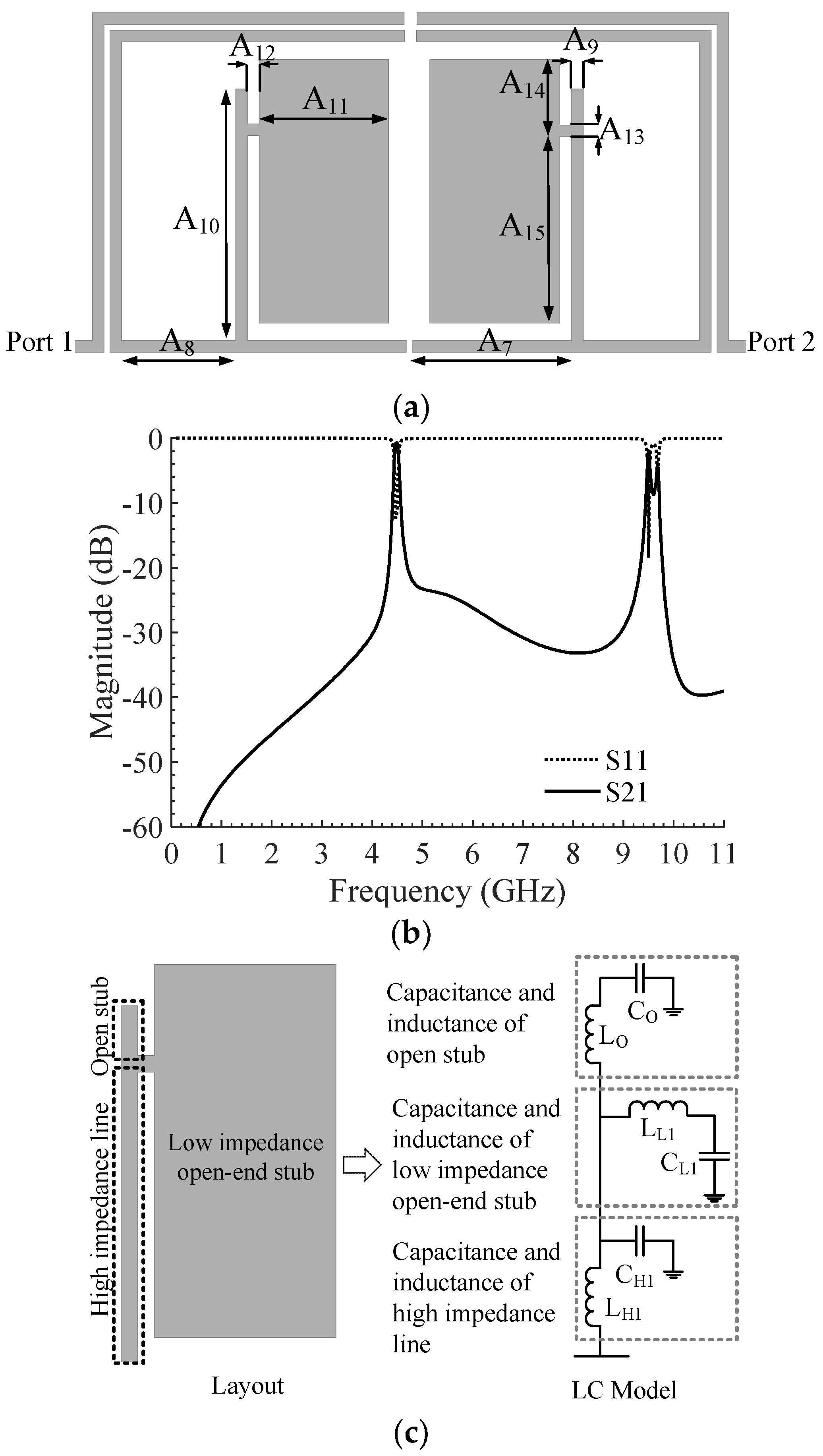
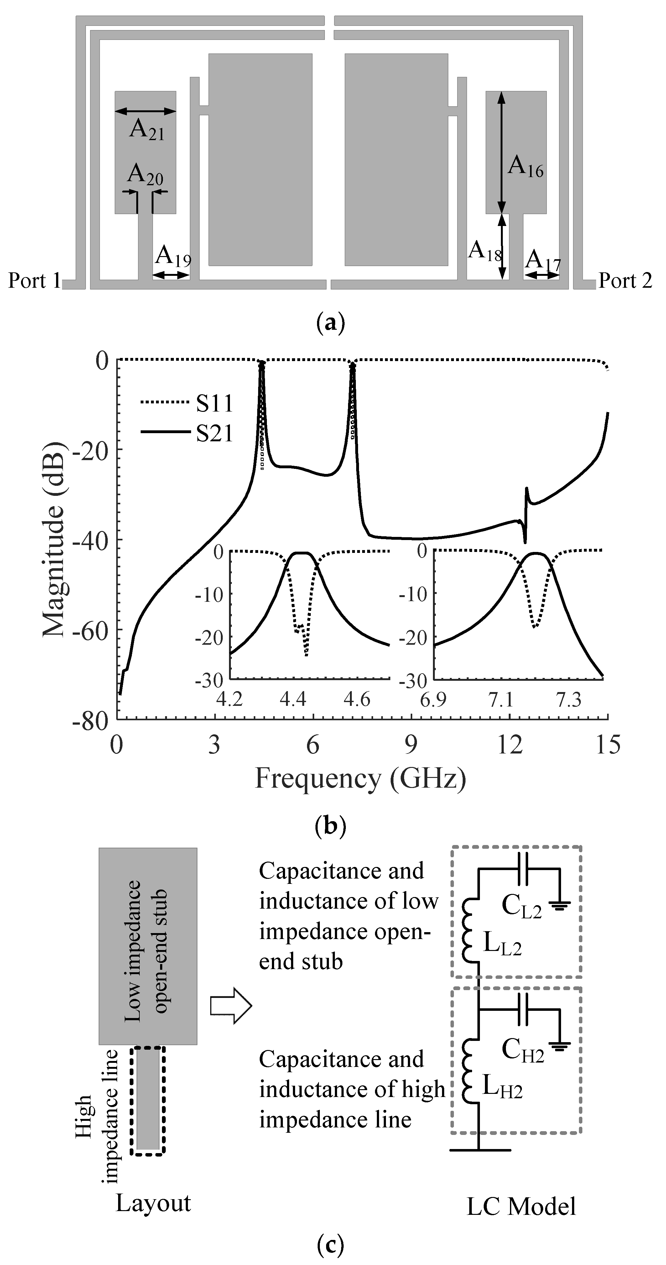
2.2. Proposed Dual-Band BPF

In order to realize an independently controllable dual passband and to shift the operating frequencies of the filter to the lower bands without scaling the filter layout, which leads to an undesirable large circuit size, a pair of flag-shaped resonators are designed and connected to the aforementioned bended coupling configuration as shown in Figure 5a. Applying the flag-shaped resonators pushes down the lower and upper passbands to 4.42 GHz and 9.5 GHz, respectively, as shown in Figure 5b. Each flag-shaped resonator comprises a high impedance line, a high impedance open stub and a low impedance open-end stub. Each section can be modeled using a series inductor and one shunt capacitor as depicted in Figure 5c. In this model, CH1 and LH1 describe capacitance and inductance of the high impedance line. CL1 and LL1 are capacitance and inductance of the low impedance open-end stub. Additionally, capacitance and inductance of the open stub are presented by CO and LO, respectively. In order to calculate the lumped element values of this LC model, the method described in [6,56,61] can be used, in which the initial values are calculated [60] and then optimized to match the frequency responses of the LC model and the electromagnetic (EM) simulation.
To lower the insertion loss of the second passband, a pair of stepped-impedance resonators, including a high impedance line and a low impedance open-end stub, are added to the BPF. The final geometrical configuration of the proposed BPF is shown in Figure 6a. The EM simulation results of this structure are presented in Figure 6b. The capacitances and inductances of the stepped-impedance lines are displayed in Figure 6c. In the LC model, the capacitance and inductance of the high impedance line are depicted by CH2 and LH2. CL2 and LL2 denote the capacitance and inductance of the low impedance open-end stub, respectively.

2.3. Current Distribution Analysis

The filtering mechanism of the proposed dual-band BPF can be further investigated using the current density distributions at the passband frequencies (4.42 GHz and 7.2 GHz) and at the stopband frequencies (1.75 GHz and 6.3 GHz) as demonstrated in Figure 7. It can be seen that both the open stubs and the resonators along with the bended coupling system experience a strong current flow, resulting in a very small insertion loss in the operating frequencies of the filter (left-side snapshots in Figure 7). However, the bended coupling system does not allow flowing strong currents at out-of-band frequencies (right-side snapshots in Figure 7), leading to large insertion loss outside of the operating frequencies of the filter. As can be seen, the flag-shaped resonators at 4.42 GHz dominantly contribute to the first passband, while, in the case of the second passband, both stepped-impedance and flag-shaped resonators contribute to create the passband.

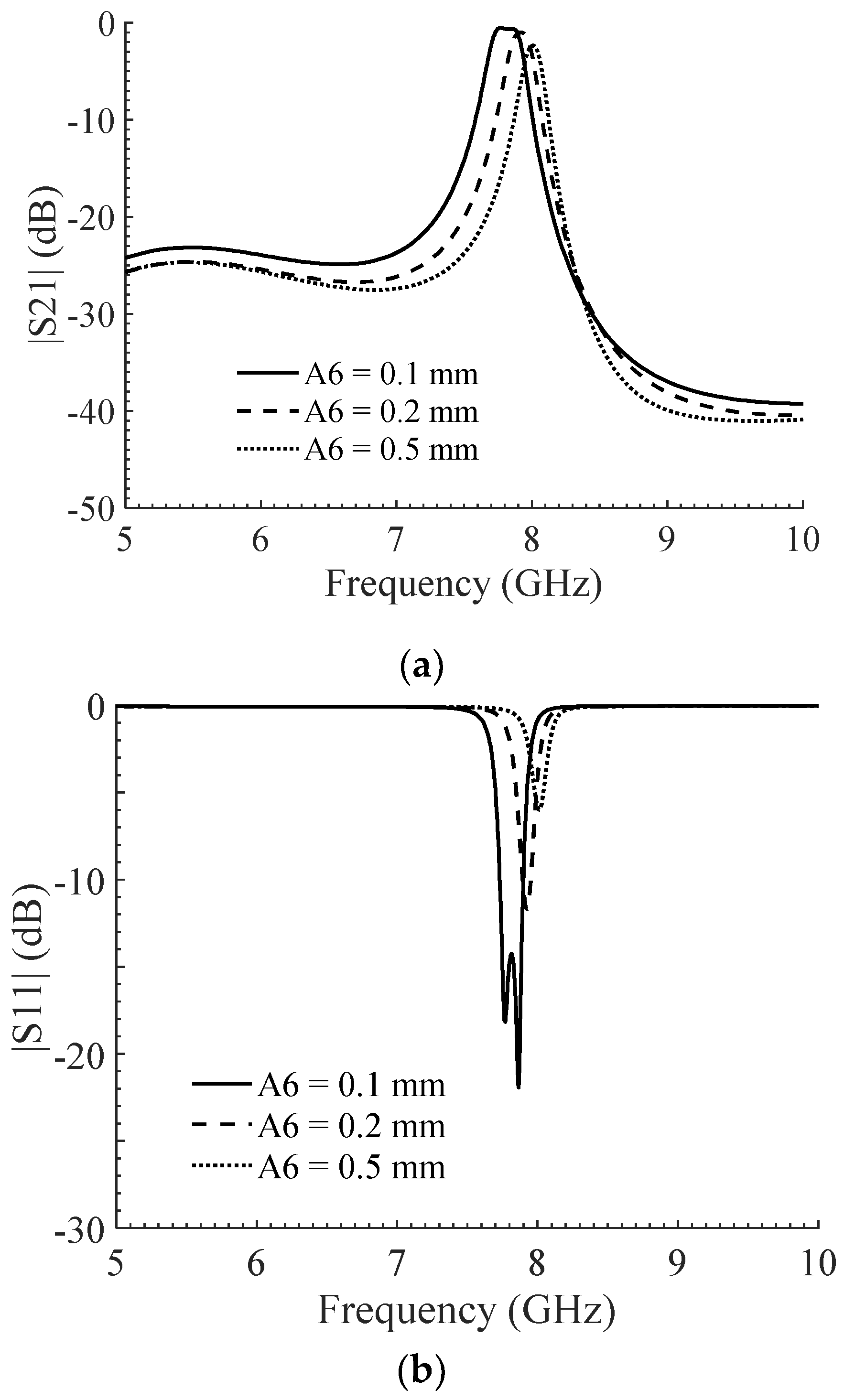
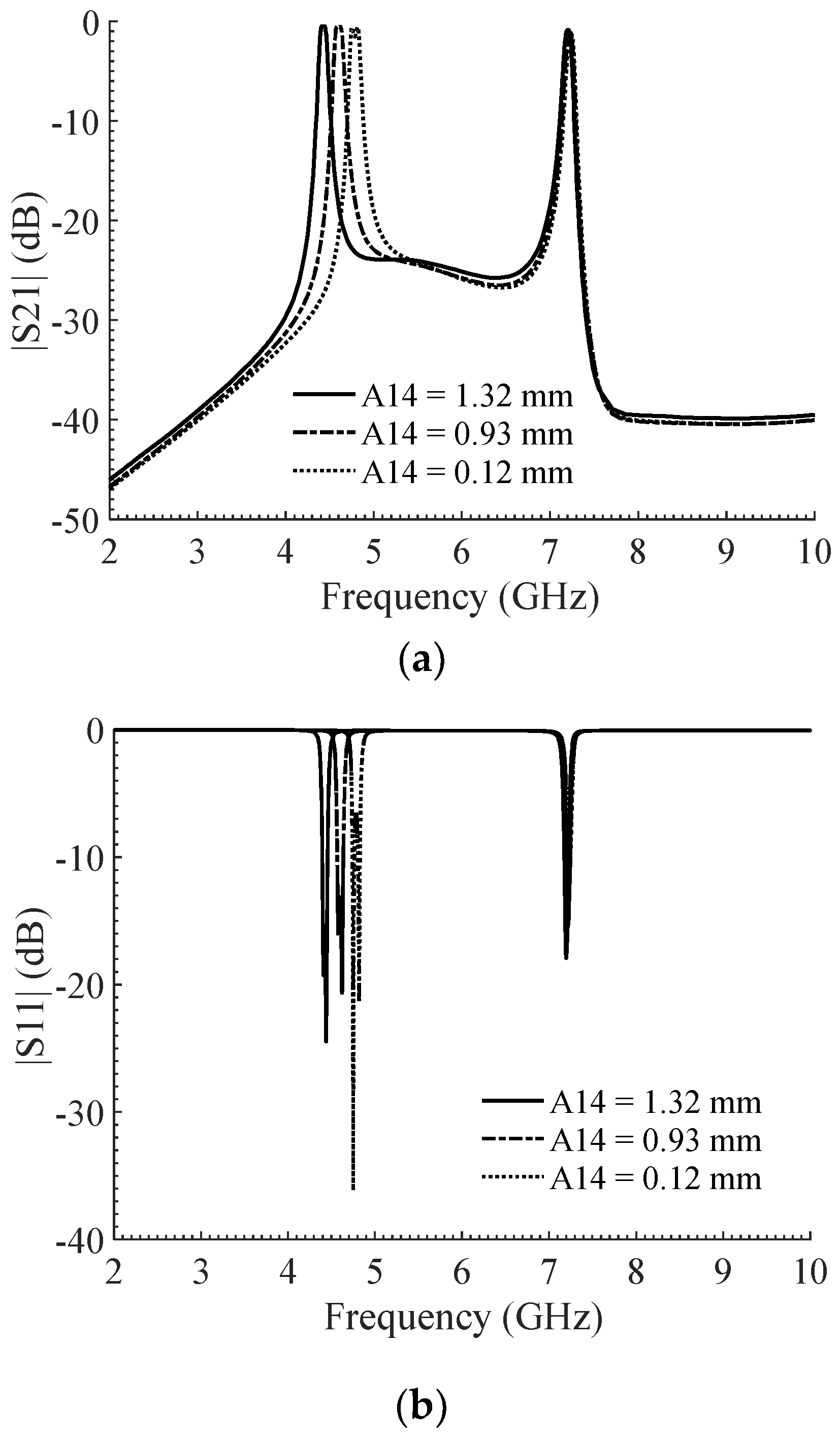
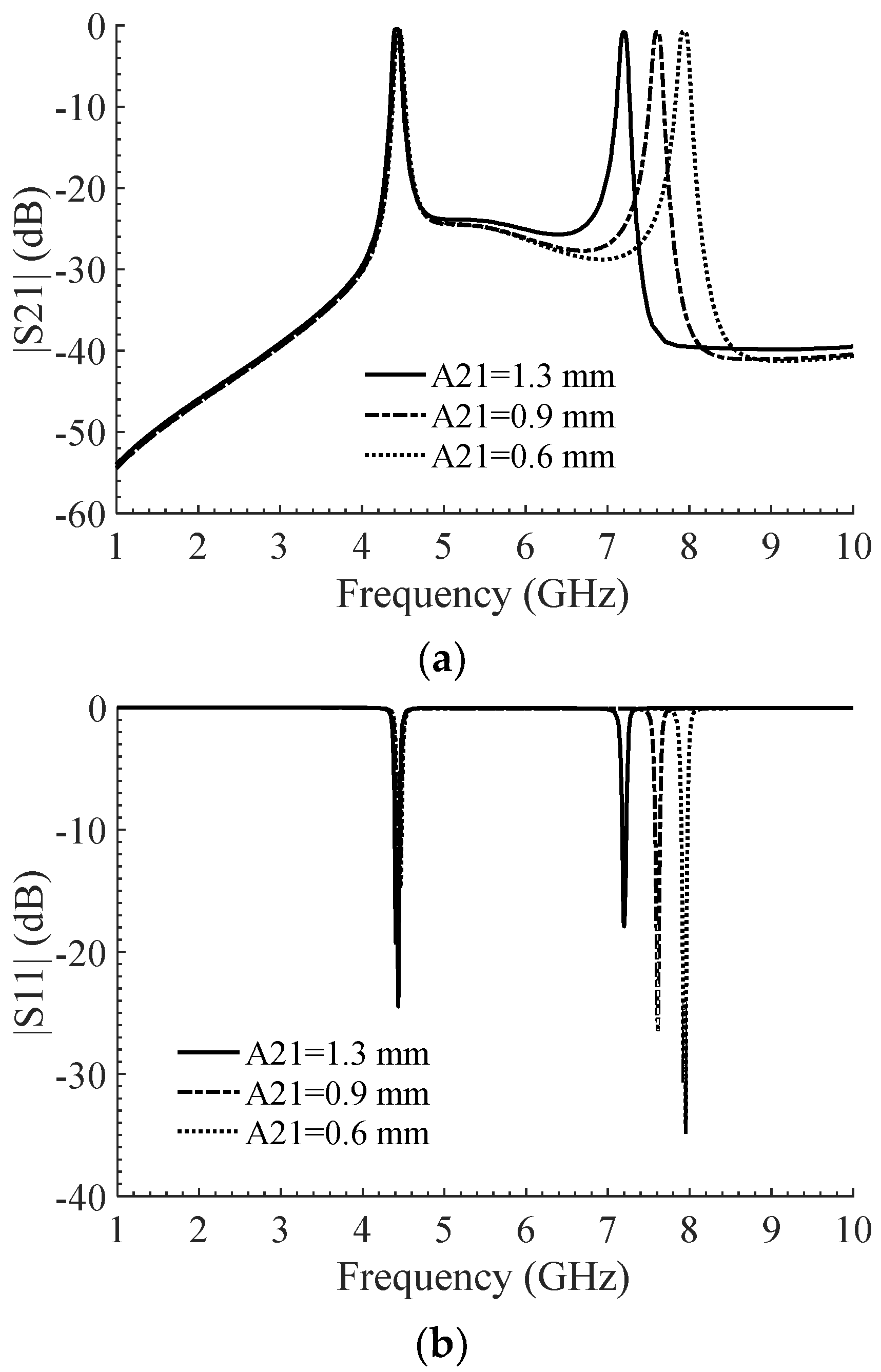
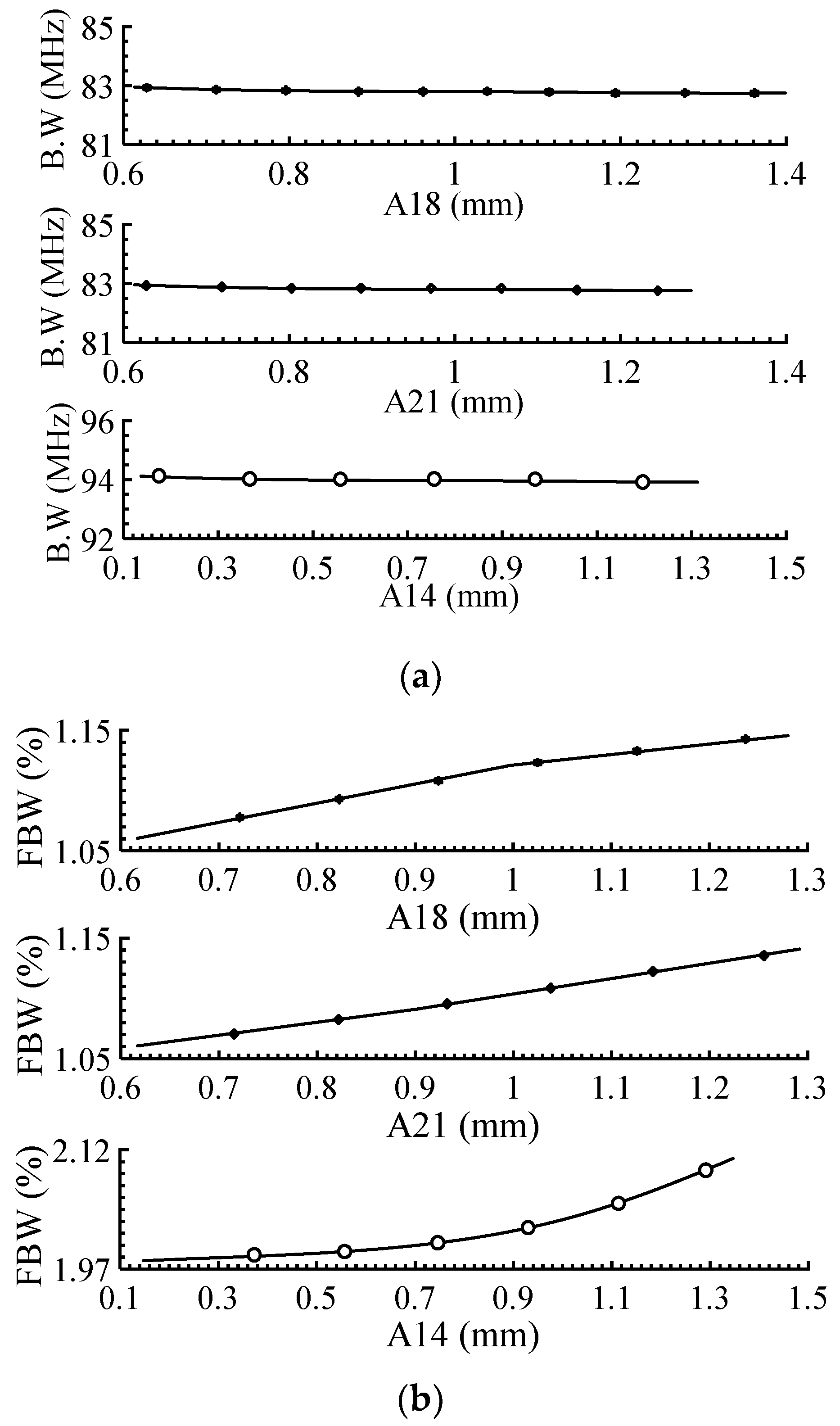
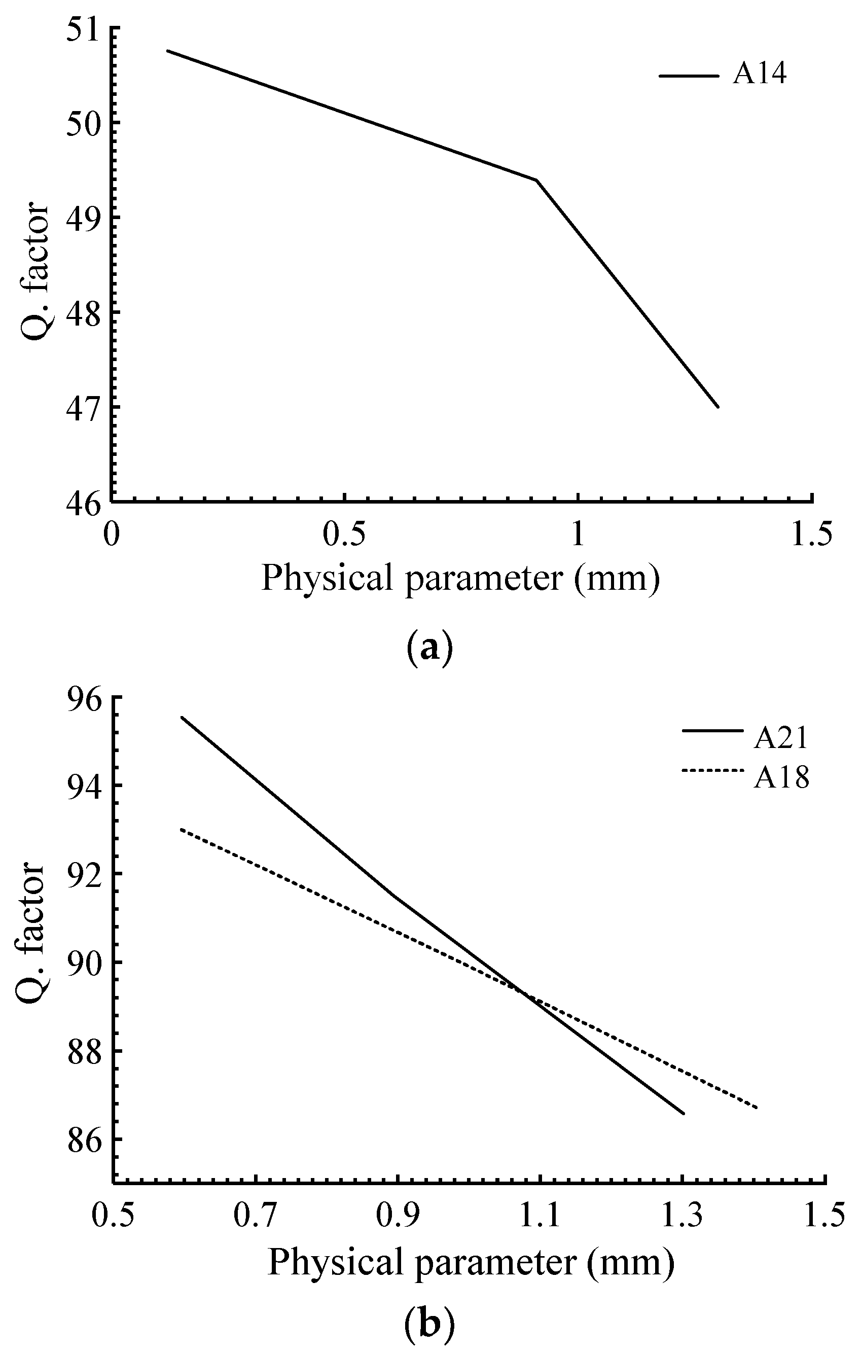
2.4. Passbands Optimization and Tuning of the Filter

One of the major merits of the proposed dual-band BPFs is their configurable passbands so that they can be tuned throughout the C-band without the need for any active or additional modules. The lower band of the proposed filter can be tuned by varying the capacitive section of the flag-shaped resonators (A14), where decreasing A14 would decrease the capacitive effects, shifting the resonance frequency to higher frequencies, resulting in 600 MHz dynamic range (4.4 GHz to 5 GHz) as shown in Figure 8. The second passband can be adjusted by either varying the capacitive (A21) or inductive (A18) sections of the stepped-impedance resonators. Indeed, increasing A21 or A18 would have the same effect on the upper band, increasing the associated capacitor and inductor, respectively, shifting the upper band to lower frequencies. As shown in Figure 9 and Figure 10, the upper band has a large dynamic range of 1000 MHz (from 7 GHz to 8 GHz).
The tunable effects of the filter passbands are depicted in Figure 11. As shown in this figure, the fractional bandwidths (FBWs) of both passbands increase slightly as a result of pushing down the first and second center frequencies, while the actual bandwidths remain almost unchanged. It needs to be mentioned that re-prototyping is required for the practical implementation of this tunability.
Quality factor (Q. factor) is defined as the ratio of operating frequency and bandwidth as shown in (4). Figure 12 shows the Q. factor of the proposed filter as a function of the three physical parameters of A18, A21 and A14. As depicted in this figure, the Q. factor decreases by increasing A18, A21 and A14.
Q . f a c t o r = f 0 B . W

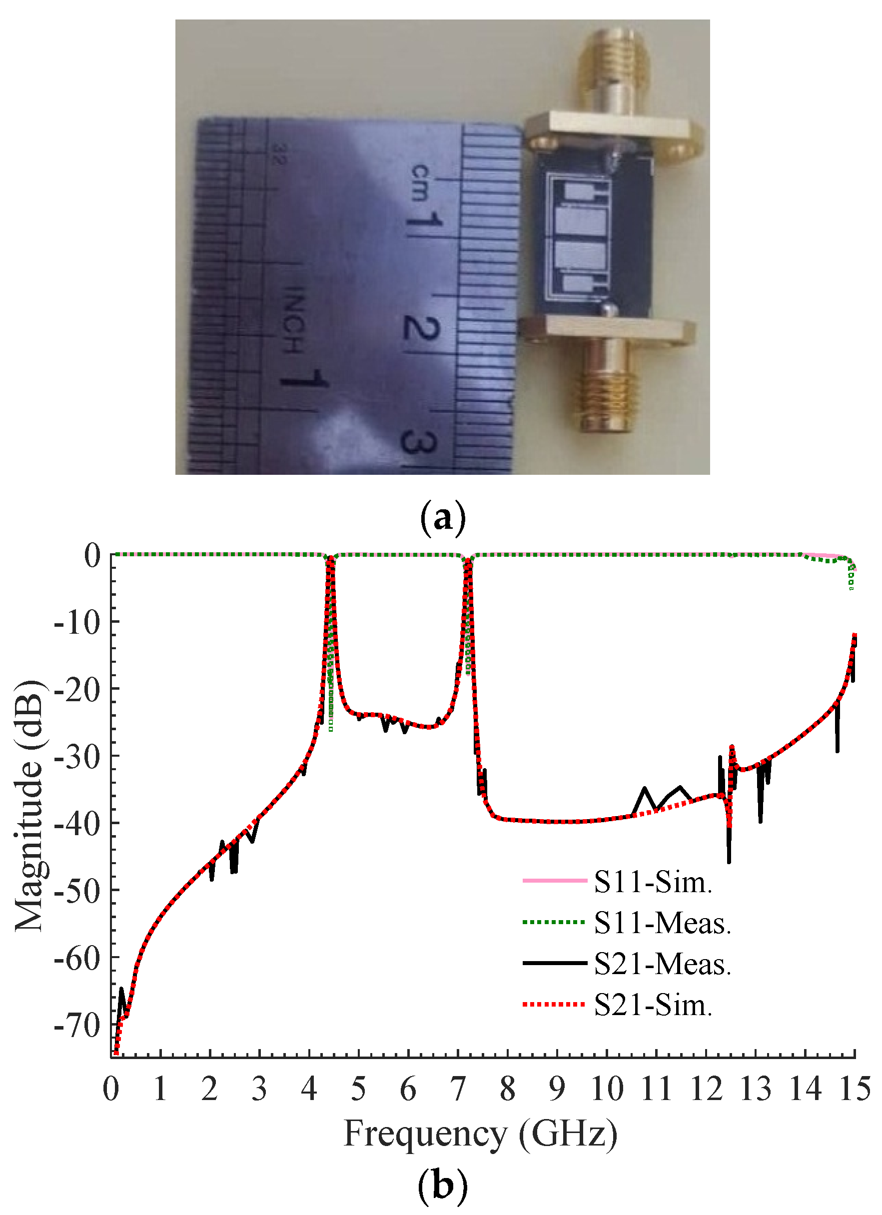
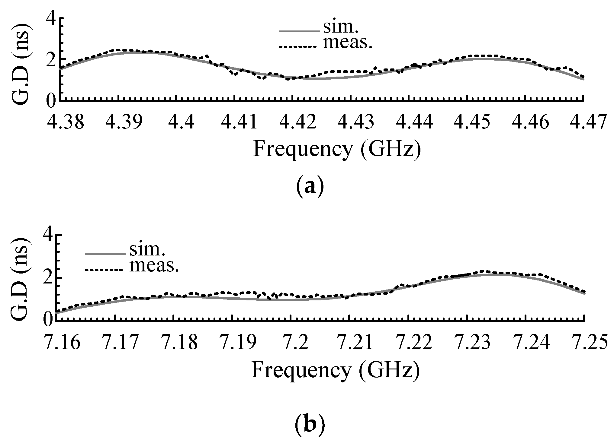
3. Results and Discussions

As shown in Figure 13a, the proposed filter is fabricated on a Rogers Duroid 5880 (Rogers Corporation, Chandler, AZ, USA) substrate with a dielectric constant of 2.2, thickness of 0.508 mm and loss-tangent of 0.0009. The frequency response of the prototyped dual-band BPF is measured by the Agilent N5230A (Agilent Technologies, Santa Clara, CA, USA) network analyzer. The proposed filter simulation was performed using the Advanced Design System 2011.10 (ADS) software, and the EM simulated and experimental results are compared in Figure 13b. According to the measurement, the filter has two passbands with the center frequencies of f1 = 4.42 GHz and f2 = 7.2 GHz, and 3 dB bandwidths of 94 MHz and 83 MHz, respectively. Insertion and return losses at f1 and f2 are about 0.5/17.56 and 0.86/17.9 dB, respectively. The filter provides an excellent out-of-band response, showing a good rejection level of 30 dB in the lower stopband, and a 24 dB isolation level with a 25 dB rejection at upper stopband, which extends up to 14.5 GHz. The measured physical size of the filter is 11.4 mm × 5.8 mm corresponding to 0.23 λg × 0.11 λg, where λg is the guided wavelength at 4.42 GHz. The fabricated filter shows a good selectivity in both bands with sharpness values of 106 dB/GHz and 212 dB/GHz, respectively, calculated using the filter sharpness formula in [61].
The proposed filter has an acceptable group delay (GD) in both passbands, which is plotted in Figure 14a,b. The maximum variations of GD in the first and second passbands are about 1.33 ns and 1.72 ns, respectively, demonstrating a flat group delay in the two passbands.
In Table 1, a summarized comparison is made between some of the recently reported dual-band BPFs and the proposed one. In this table, the normalized circuit size (NCS) is computed using NCS = (physical size)/ λ g 2 [62,63]. The properties of the proposed filter and some of the recently reported BPFs are listed in Table 1. As can be seen, the proposed filter has the lowest insertion loss in the two passbands, the highest suppression levels in the upper stopbands, and the widest upper stopband as compared with the reported works in [34,35,36,37,38,39,40,41,42,43,44]. It can also be observed that the return loss in passbands is better than the works reported in [36,43,45]. In addition, the presented BPF provides a large tuning range as compared with other works in Table 1. Among the recently reported designs, the proposed BPF offers dual adjustable passbands over the widely used C-band frequency regime for applications such as satellite modems, transceivers and wireless networking technologies based on the IEEE 802.11 family of standards.

4. Conclusions

In this paper, a microstrip dual-band BPF with tunable narrow passbands, miniaturized size, sharp response and low-cost fabrication has been designed and fabricated at C-band frequencies. The proposed filter consists of three subsections including a bended coupling system, flag-shaped resonators and stepped-impedance resonators. The coupling system is based on an end-coupled resonator responsible for creating a weak coupling required for a narrowband response. The quality of the response and the selectivity of the filter is then improved by introduction of flag-shaped and stepped-impedance resonators. The measured results show that the filter has two independent passbands centered at 4.42 and 7.2 GHz with a good isolation level of 24 dB and strong attenuations of 25 and 30 dB in the lower and upper stopbands, respectively. The proposed filter shows excellent selectivity with its sharpness values of 106 and 212 dB/GHz at its lower and upper bands.

Author Contributions

Conceptualization, A.L., A.G., W.M. and K.W.K.; methodology A.L., A.G. and W.M.; software, A.L., A.G. and W.M.; validation, A.L., A.G., W.M., R.B.V.B.S., N.B.-M., M.S.A., G.H.L. and K.W.K.; formal analysis, A.L., A.G., W.M., R.B.V.B.S., N.B.-M., M.S.A., G.H.L. and K.W.K.; investigation, A.L., A.G., W.M., R.B.V.B.S., N.B.-M., M.S.A., G.H.L. and K.W.K.; resources, A.L., A.G., W.M., R.B.V.B.S., N.B.-M., M.S.A., G.H.L. and K.W.K.; data curation, A.L., A.G., W.M., R.B.V.B.S., N.B.-M., M.S.A., G.H.L. and K.W.K.; writing—original draft preparation, A.L., A.G., W.M., R.B.V.B.S., N.B.-M. and M.S.A.; writing—review and editing, A.L., A.G., W.M., R.B.V.B.S., N.B.-M., M.S.A., G.H.L. and K.W.K.; visualization, A.L. and A.G.; supervision, W.M. and K.W.K.; project administration, W.M., G.H.L. and K.W.K.; funding acquisition, G.H.L. and K.W.K. All authors have read and agreed to the published version of the manuscript.

Funding

This research was supported by the National R&D Program through the National Research Foundation of Korea (NRF) funded by the Ministry of Education, Science and Technology (No. NRF-2019M1A7A1A02085630) and also supported by the BK21 Plus project funded by the Ministry of Education, Korea (21A20131600011).

Conflicts of Interest

The authors declare no conflict of interest.

References

  1. Karimi, G.; Pourasad, Y.; Lalbakhsh, A.; Siahkamari, H.; Mohamadzade, B. Deign of a compact ultra-narrow band dual band filter for WiMAX application. AEU Int. J. Electron. Commun. 2019, 110, 152827. [Google Scholar] [CrossRef]
  2. Roshani, S.; Roshani, S.; Zarinitabar, A. A modified Wilkinson power divider with ultra harmonic suppression using open stubs and lowpass filters. Analog Integr. Circ. Signal Process. 2019, 98, 395–399. [Google Scholar] [CrossRef]
  3. Ghaderi, A.; Golestanifar, A.; Shama, F. Microstrip bandpass filters using coupled feed lines for third and fourth generation communications. AEU Int. J. Electron. Commun. 2018, 86, 195–201. [Google Scholar] [CrossRef]
  4. Amirian, M.; Karimi, G.; Lalbakhsh, A.; Bayati, M.S. Compact differential bandpass filter with a narrow notched band using APCL structure suitable for UWB application. Microelectron. J. 2015, 46, 869–874. [Google Scholar] [CrossRef]
  5. Rostami, P.; Roshani, S. A miniaturized dual band Wilkinson power divider using capacitor loaded transmission lines. AEU Int. J. Electron. Commun. 2018, 90, 63–68. [Google Scholar] [CrossRef]
  6. Karimi, G.; Lalbakhsh, A.; Dehghani, K.; Siahkamari, H. Analysis of novel approach to design of ultra-wide stopband microstrip low-pass filter using modified U-shaped resonator. ETRI J. 2015, 37, 945–950. [Google Scholar] [CrossRef]
  7. Malakooti, S.A.; Mousavi, S.M.; Fumeaux, C. Tunable bandpass-to-bandstop quasi-Yagi–Uda antenna with sum and difference radiation patterns. IEEE Transact. Antennas Propag. 2019, 67, 2260–2271. [Google Scholar] [CrossRef]
  8. Karimi, G.; Amirian, M.; Lalbakhsh, A.; Ranjbar, M. A new microstrip coupling system for realization of a differential dual-band bandpass filter. AEU Int. J. Electron. Commun. 2019, 99, 186–192. [Google Scholar] [CrossRef]
  9. Jamshidi, M.; Siahkamari, H.; Roshani, S.; Roshani, S. A compact Gysel power divider design using U-shaped and T-shaped resonators with harmonics suppression. Electromagnetics 2019, 39, 1–4. [Google Scholar] [CrossRef]
  10. Lalbakhsh, A.; Karimi, G.; Sabaghi, F. Triple mode spiral wideband bandpass filter using symmetric dual-line coupling. Electron. Lett. 2017, 53, 795–797. [Google Scholar] [CrossRef]
  11. Ghaderi, A.; Golestanifar, A.; Shama, F. Design of a compact microstrip tunable dual-band bandpass filter. AEU Int. J. Electron. Commun. 2017, 82, 391–396. [Google Scholar] [CrossRef]
  12. Doumanis, E.; Goussetis, G.; Kosmopoulos, S. Filter Design for Satellite Communications: Helical Resonator Technology; Artech House: Norwood, MA, USA, 2015. [Google Scholar]
  13. Hunter, I.C.; Billonet, L.; Jarry, B.; Guillon, P. Microwave filters-applications and technology. IEEE Transact. Microw. Theory Tech. 2002, 50, 794–805. [Google Scholar] [CrossRef]
  14. Shaman, H.N. Design of a compact C-band microstrip bandpass filter for satellite communications applications. In Proceedings of the Ninth International Conference on Wireless and Optical Communications Networks (WOCN), Indore, India, 20–22 September 2012; pp. 1–4. [Google Scholar]
  15. Lagunas, E.; Tsinos, C.G.; Sharma, S.K.; Chatzinotas, S. 5G cellular and fixed satellite service spectrum coexistence in C-band. IEEE Access 2020, 8, 72078–72094. [Google Scholar] [CrossRef]
  16. Afzal, M.U.; Lalbakhsh, A.; Esselle, K.P. A low-profile beam-tilted antenna array for receiving direct-broadcast satellite services. In Proceedings of the IEEE Asia-Pacific Conference on Antennas and Propagation (APCAP), Auckland, New Zealand, 5–8 August 2018; pp. 147–148. [Google Scholar]
  17. Lalbakhsh, A.; Afzal, M.U.; Esselle, K.P.; Smith, S.L. Low-cost non-uniform metallic lattice for rectifying aperture near-field of electromagnetic bandgap resonator antennas. IEEE Trans. Antennas Propag. 2020, 68, 3328–3335. [Google Scholar] [CrossRef]
  18. Eng, J.E.; Frank, S.Y. Low Cost Millimeter Wave Receiver and Method for Operating Same. U.S. Patent 10,263,648, 16 April 2019. [Google Scholar]
  19. Afzal, M.U.; Lalbakhsh, A.; Esselle, K.P. Electromagnetic-wave beam-scanning antenna using near-field rotatable graded-dielectric plates. J. Appl. Phys. 2018, 124, 912–915. [Google Scholar] [CrossRef]
  20. Gómez-García, R.; Muñoz-Ferreras, J.M.; Feng, W.; Psychogiou, D. Balanced symmetrical quasi-reflectionless single-and dual-band bandpass planar filters. IEEE Microw. Wirel. Compon. Lett. 2018, 3, 1–3. [Google Scholar] [CrossRef]
  21. Sans, M.; Selga, J.; Vélez, P.; Bonache, J.; Rodríguez, A.; Boria, V.E.; Martín, F. Compact wideband balanced bandpass filters with very broad common-mode and differential-mode stopbands. IEEE Trans. Microw. Theory Tech. 2018, 66, 737–750. [Google Scholar] [CrossRef]
  22. Song, Y.; Liu, H.; Zhao, W.; Wen, P.; Wang, Z. Compact balanced dual-band bandpass filter with high common-mode suppression using planar via-free CRLH resonator. IEEE Microw. Wirel. Compon. Lett. 2018, 28, 996–998. [Google Scholar] [CrossRef]
  23. Fernández-Prieto, A.; Martel, J.; Ugarte-Parrado, P.J.; Lujambio, A.; Martinez-Ros, A.J.; Martín, F.; Medina, F.; Boix, R.R. Compact balanced dual-band bandpass filter with magnetically coupled embedded resonators. IET Microw. Antennas Propag. 2019, 13, 492–497. [Google Scholar] [CrossRef]
  24. Gu, H.; Ge, L.; Xu, L. Simple dual-mode balanced bandpass filter with high selectivity and extended common-mode noise suppression. Electron. Lett. 2018, 54, 833–835. [Google Scholar] [CrossRef]
  25. Yang, L.; Zhu, L.; Zhang, R.; Wang, J.; Choi, W.W.; Tam, K.W.; Gómez-García, R. Novel multilayered ultra-broadband bandpass filters on high-impedance slotline resonators. IEEE Trans. Microw. Theory Tech. 2018, 67, 129–139. [Google Scholar] [CrossRef]
  26. Qiao, H.; Guo, D.; Mou, J.; Li, M.; Ma, Z.; Lv, X. HIS-based bandpass filter with improved upper-stopband performance. Electron. Lett. 2018, 54, 363–364. [Google Scholar] [CrossRef]
  27. Xu, H.; Wang, J.; Zhu, L.; Huang, F.; Wu, W. Design of a dual-mode balun bandpass filter with high selectivity. IEEE Microw. Wirel. Compon. Lett. 2017, 28, 22–24. [Google Scholar] [CrossRef]
  28. Li, P.; Chu, H.; Zhao, D.; Chen, R.S. Compact dual-band balanced SIW bandpass filter with improved common-mode suppression. IEEE Microw. Wirel. Compon. Lett. 2017, 27, 347–349. [Google Scholar] [CrossRef]
  29. Wang, S.; Zhang, D.; Zhang, Y.; Qing, L.; Zhou, D. Novel dual-mode bandpass filters based on SIW resonators under different boundaries. IEEE Microw. Wirel. Compon. Lett. 2016, 27, 28–30. [Google Scholar] [CrossRef]
  30. Lotfi-Neyestanak, A.A.; Lalbakhsh, A. Improved microstrip hairpin-line bandpass filters for spurious response suppression. Electron lett. 2012, 48, 858–859. [Google Scholar] [CrossRef]
  31. Lalbakhsh, A.; Neyestanak, A.A.; Naser-Moghaddasi, M. Microstrip hairpin bandpass filter using modified Minkowski fractal-shape for suppression of second harmonic. IEICE Trans. Electron. 2012, 95, 378–381. [Google Scholar] [CrossRef]
  32. Zhang, R.; Zhu, L. Design of a compact dual-band bandpass filter using coupled stepped-impedance resonators. IEEE Microw. Wirel. Compon. Lett. 2014, 24, 155–157. [Google Scholar] [CrossRef]
  33. Xiang, K.R.; Chen, F.C. Compact microstrip bandpass filter with multispurious suppression using quarter-wavelength and half-wavelength uniform impedance resonators. IEEE Access 2018, 6, 20364–20370. [Google Scholar] [CrossRef]
  34. Chen, C.F.; Wang, G.Y.; Li, J.J. Compact microstrip dual-band bandpass filter and quad-channel diplexer based on quint-mode stub-loaded resonators. IET Microw. Antennas Propag. 2018, 12, 1913–1919. [Google Scholar] [CrossRef]
  35. Zhu, C.; Xu, J.; Zhang, G.; Kang, W.; Wu, W. Split-type dual-band bandpass filters with symmetric/asymmetric response. IEEE Microw. Wirel. Compon. Lett. 2017, 28, 25–27. [Google Scholar] [CrossRef]
  36. Wang, L.T.; Xiong, Y.; Gong, L.; Zhang, M.; Li, H.; Zhao, X.J. Design of dual-band bandpass filter with multiple transmission zeros using transversal signal interaction concepts. IEEE Microw. Wirel. Compon. Lett. 2018, 17, 32–34. [Google Scholar] [CrossRef]
  37. Ren, B.; Ma, Z.; Liu, H.; Guan, X.; Wen, P.; Wang, X.; Masataka, O. Miniature dual-band bandpass filter using modified quarter-wavelength SIRs with controllable passbands. Electron. Lett. 2018, 55, 38–40. [Google Scholar] [CrossRef]
  38. Deng, H.W.; Liu, F.; Xu, T.; Sun, L.; Xue, Y.F. Compact and high selectivity dual-mode microstrip BPF with frequency-dependent source–load coupling. Electron. Lett. 2018, 54, 219–221. [Google Scholar] [CrossRef]
  39. Ieu, W.; Zhang, D.; Zhou, D. High-selectivity dual-mode dual-band microstrip bandpass filter with multi-transmission zeros. Electron. Lett. 2017, 53, 482–484. [Google Scholar] [CrossRef]
  40. Liu, H.; Ren, B.; Guan, X.; Lei, J.; Li, S. Compact dual-band bandpass filter using quadruple-mode square ring loaded resonator (SRLR). IEEE Microw. Wirel. Compon. Lett. 2013, 23, 181–183. [Google Scholar]
  41. Xu, L.J.; Zhang, G.; Tang, Y.M.; Bo, Y.M. Compact dual-mode dual-band bandpass filter with wide stopband for WLAN applications. Electron. Lett. 2015, 51, 1372–1374. [Google Scholar] [CrossRef]
  42. Peng, Y.; Zhang, L.; Fu, J.; Wang, Y.; Leng, Y. Compact dual-band bandpass filter using coupled lines multimode resonator. IEEE Microw. Wirel. Compon. Lett. 2015, 25, 235–237. [Google Scholar] [CrossRef]
  43. Zhang, Z.C.; Chu, Q.X.; Chen, F.C. Compact dual-band bandpass filters using open-/short-circuited stub-loaded λ/4 resonators. IEEE Microw. Wirel. Compon. Lett. 2015, 25, 657–659. [Google Scholar] [CrossRef]
  44. Shen, G.; Che, W.; Feng, W.; Xue, Q. Analytical design of compact dual-band filters using dual composite right-/left-handed resonators. IEEE Trans. Microw. Theory Tech. 2016, 65, 804–814. [Google Scholar] [CrossRef]
  45. Zhu, H.; Abbosh, A.M. Single-and dual-band bandpass filters using coupled stepped-impedance resonators with embedded coupled-lines. IEEE Microw. Wirel. Compon. Lett. 2016, 26, 675–677. [Google Scholar] [CrossRef]
  46. Lalbakhsh, A.; Afzal, M.U.; Zeb, B.A.; Esselle, K.P. Design of a dielectric phase-correcting structure for an EBG resonator antenna using particle swarm optimization. In Proceedings of the IEEE. International Symposium on Antennas Propagation (ISAP), Hobart, Australia, 9–12 November 2015; pp. 408–410. [Google Scholar]
  47. Jamshidi, M.B.; Lalbakhsh, A.; Mohamadzade, B.; Siahkamari, H.; Mousavi, S.M.H. A novel neural-based approach for design of microstrip filters. AEU Int. J. Electron. Commun. 2019, 110, 152847. [Google Scholar] [CrossRef]
  48. Lalbakhsh, P.; Zaeri, B.; Lalbakhsh, A.; Fesharaki, M.N. AntNet with reward-penalty reinforcement learning. In Proceedings of the Second International Conference on Computational Intelligence, Communication Systems and Networks (CICSYN), Liverpool, UK, 28–30 July 2010; pp. 17–21. [Google Scholar]
  49. Jamshidi, M.; Lalbakhsh, A.; Lotfi, S.; Siahkamari, H.; Mohamadzade, B.; Jalilian, J. A Neuro-based approach to designing a Wilkinson power divider. Int. J. RF Microw. Comput. Aided Eng. 2020, 30, e22091. [Google Scholar] [CrossRef]
  50. Lalbakhsh, A.; Afzal, M.U.; Esselle, K. Simulation-driven particle swarm optimization of spatial phase shifters. In Proceedings of the 18th IEEE international Conference on Electromagnetics in Advanced Applications (ICEAA), Australia, Cairns, Australia, 19–23 September 2016; pp. 428–430. [Google Scholar]
  51. Jamshidi, M.B.; Lalbakhsh, A.; Alibeigi, N.; Soheyli, M.R.; Oryani, B.; Rabbani, N. Socialization of industrial robots: An innovative solution to improve productivity. In Proceedings of the IEEE 9th Annual Information Technology, Electronics and Mobile Communication Conference (IEMCON), Vancouver, BC, Canada, 1–3 November 2018; pp. 832–837. [Google Scholar]
  52. Lalbakhsh, P.; Zaeri, B.; Lalbakhsh, A. An improved model of ant colony optimization using a novel pheromone update strategy. IEICE Trans. Inf. Syst. 2013, 96, 2309–2318. [Google Scholar] [CrossRef] [Green Version]
  53. Parinam, S.; Sharma, A.L.; Kumar, V.P.; Kumar, M.; Kumari, N.; Mittal, S.; Karar, V. Optimization of optical parameters for the design of multilayer bandpass filter using genetic algorithm. Mater. Today Proc. 2018, 5, 5091–5096. [Google Scholar] [CrossRef]
  54. Ieu, W.; Zhang, D.; Lv, D.; Wu, Y. Dual-band microstrip bandpass filter with independently-tunable passbands using patch resonator. Electron. Lett. 2018, 54, 665–667. [Google Scholar] [CrossRef]
  55. Khani, S.; Makki, S.V.A.D.; Mousavi, S.M.H.; Danaie, M.; Rezaei, P. Adjustable compact dual-band microstrip bandpass filter using T-shaped resonators. Microw. Opt. Technol. Lett. 2017, 59, 2970–2975. [Google Scholar] [CrossRef]
  56. Karimi, G.; Siahkamari, H.; Hamedani, F.K.; Lalbakhsh, A. Design of modified Z-shaped and T-shaped microstrip filter based on transfer function analysis. Wirel Pers. Commun. 2015, 82, 2005–2016. [Google Scholar] [CrossRef]
  57. Mousavi, S.M.; Raziani, S.; Falihi, A. Design of high performance microstrip lpf with analytical transfer function. Frequenz 2017, 72, 63–71. [Google Scholar] [CrossRef]
  58. Sariri, H.; Rahmani, Z.; Lalbakhsh, A.; Majidifar, S. Compact LPF using T-shaped resonator. Frequenz 2013, 67, 17–20. [Google Scholar] [CrossRef]
  59. Pirasteh, A.; Roshani, S.; Roshani, S. Compact microstrip lowpass filter with ultra sharp response using a square-loaded modified T-shaped resonator. Turkish J. Electr. Eng. Comput. Sci. 2018, 26, 1736–1746. [Google Scholar] [CrossRef]
  60. Hong, J.S.G.; Lancaster, M.J. Microstrip Filters for RF/Microwave Applications; John Wiley & Sons: Hoboken, NJ, USA, 2004; Volume 167. [Google Scholar]
  61. Karimi, G.; Lalbakhsh, A.; Siahkamari, H. Design of sharp roll-off lowpass filter with ultra-wide stopband. IEEE Microw. Wirel. Compon. Lett. 2013, 23, 303–305. [Google Scholar] [CrossRef]
  62. Dehghani, K.; Karimi, G.; Lalbakhsh, A.; Maki, S.V. Design of lowpass filter by using a novel stepped impedance resonator. Electron. Lett. 2014, 50, 37–39. [Google Scholar] [CrossRef]
  63. Karimi, G.; Golestanifar, A.; Ghaderi, A.; Salimpour, N. Ultra sharp transition-band low-pass filter with miniaturized size for GSM applications. Radioengineering 2018, 27, 425–430. [Google Scholar] [CrossRef]
Figure 1. End-coupled transmission line: (a) Layout, (b) electromagnetic (EM) simulation.
Electronics 09 01088 g001
Figure 2. Bended coupling system: (a) Layout, A1 = 5.3, A2 = 4.8, A3 = 5.6, A4 = 5.1, A5 = 4.8, A6 = 0.1 (all in mm), (b) EM simulation.
Electronics 09 01088 g002
Figure 3. Bended coupling system: (a) lumped-element circuit (LC) model, (b) LC simulation.
Electronics 09 01088 g003
Figure 4. Adjustability of the lower passband by varying A6: (a) |S21|, (b) |S11|.
Electronics 09 01088 g004
Figure 5. Integration of flag-shaped resonators with the bended coupled system. (a) Layout, (b) EM simulation, (c) LC model of flag-shaped resonator. The dimensions of the introduced flag-shaped resonators are as follows: A7 = 2.7, A8 = 1.9, A9 = 0.2, A10 = 4.3, A11 = 2.2, A12 = 0.2, A13 = 0.2, A14 = 1.32, A15 = 3.2 (all in mm).
Electronics 09 01088 g005
Figure 6. Completed dual-band bandpass filter (BPF): (a) Layout, A16 = 2.6, A17 = 0.8, A18 = 1.4, A19 = 0.8, A20 = 0.3, A21 = 1.3 (all in mm), (b) EM simulation, (c) LC model of stepped-impedance resonator.
Electronics 09 01088 g006
Figure 7. Current density distributions of the proposed dual-band BPF.
Electronics 09 01088 g007
Figure 8. Adjustability of the lower band of the proposed BPF by varying A14: (a) |S21|, (b) |S11|.
Electronics 09 01088 g008
Figure 9. Adjustability of the upper band of the proposed BPF by varying A21: (a) |S21|, (b) |S11|.
Electronics 09 01088 g009
Figure 10. Adjustability of the upper band of the proposed BPF by varying A18: (a) |S21|, (b) |S11|.
Electronics 09 01088 g010
Figure 11. (a) Variations of bandwidth as a function of A18, A21 and A14, (b) Variations of fractional bandwidth (FBW) as a function of A18, A21 and A14.
Electronics 09 01088 g011
Figure 12. (a) Variations of Q. factor versus physical parameters: (a) A14, (b) A18 and A21.
Electronics 09 01088 g012
Figure 13. Proposed BPF: (a) A photo of the fabricated filter: (b) Simulation and measurement results.
Electronics 09 01088 g013
Figure 14. Group delay (GD): (a) first passband, (b) second passband.
Electronics 09 01088 g014
Table 1. Characteristics of proposed work and some papers.
Refs.f1/f2 (GHz)IL1/IL2 (dB)RL1/RL2 (dB)SL1/SL2 (dB)USBUSB (GHz)TR1/TR2 (MHz) NCS   ( λ g 2 )
This work4.42/7.20.5/0.8617.56/17.930/253 f17.4–15600/10000.0253
[30]0.9/2.20.5/120/2020/203 f12.4–3200/2000.0391
[32]3.8/4.81.38/1.8214/1720/202 f15.6–8500/2000.0496
[33]2.35/5.81.1/1.620/1830/203 f16.5–8-/-0.0288
[35]2.55/3.61.22/2.1320/1820/201 f13.7–5-/-0.1189
[36]2.45/5.20.6/0.920/1920/203 f16–7.5-/-0.0253
[37]2.4/5.21.4/2.730/1220/202 f16–11-/-0.0324
[38]1.57/2.41.26/2.417.5/22.620/203 f12.7–5.5-/-0.0108
[39]2.4/5.81.35/1.9717/1520/203 f16–9-/-0.0975
[40]1.6/2.560.74/0.9320/2020/202 f12.7–4.5-/-0.005
[41]2.5/3.51.2/1.212/1220/203 f14–9-/--
f1: First passband, f2: Second passband, IL1: Insertion loss at f1, IL2: Insertion loss at f2, RL1: Return loss at f1, RL2: Return loss at f2, SL1: Suppression level in lower stopband, SL2: Suppression level in upper stopband, USB: Upper Stopband bandwidth, TR1: Tuning range of f1, TR2: Tuning range of f2.

