Abstract
Many telecommunication applications require antennas capable of operating in a wide (or even ultrawide) frequency band. While LPDA (log-periodic dipole array) antennas are very practical in real-world applications, their usefulness is impeded due to frequency limitations caused by their truncated structures. To increase the upper-frequency range of the LPDA antenna, an additional parameter—the ratio factor—was introduced during the antenna geometry design process. This parameter allows us to improve the properties of an antenna with truncated geometry. In this paper, the proposed technique was used to design, manufacture and present an antenna capable of operating in a frequency range between 760 MHz to 18 GHz. The electrical properties of the proposed antenna were compared with a reference antenna. The designed antenna was experimentally validated, and the simulated results were verified as well.
1. Introduction
Nowadays, wireless communication is the fastest growing sector in the telecommunication systems industry. In the context of these systems, antenna design remains a challenging issue, especially in applications that work best with a wideband antenna. For example, broadband antenna properties are a requisite in communication systems, metrology of electromagnetic field (EM) and EM field sensing. In addition, some systems, such as cognitive radio, require an antenna capable of dynamically and autonomously emitting and/or receiving signals in the desired frequency ranges [1]. Furthermore, in MIMO, WLAN and similar applications, communication systems should be equipped with an antenna capable of supporting a wideband or even ultra-wideband (UWB) frequency range, e.g., [2,3]. Frequency independence is required in antennas used for EMC measurements as these involve scanning a wide band of frequencies. Special attention should be paid to broadband antennas used as probes for measuring radiation from cellular base station equipment. What is more, the probe must be able to measure all frequencies at the same efficiency. In this case, the probe’s antenna must be capable of delivering good performance and must demonstrate a constant measuring efficiency for all measured frequencies [4].
The log-periodic dipole array (LPDA) antenna would be the best candidate for the applications described above, as such antennas offer relatively good broadband properties. Log-periodic antennas have the same radiation resistance over their entire frequency range, and LPDA antennas based on microstrip structures are easy to design and implement. The properties of these antennas vary periodically with the logarithm of frequency. The structure of the LPDA antenna is based on linear dipoles placed in an alternating layout, which enables a 180-degree change in phase between adjacent elements. For frequency-independent antennas, this design is amongst one of the most useful.
The geometry and electrical properties of log-periodic antennas were developed in the 1950s and 1960s. The concepts for the most recognized LPDA antennas were introduced by DuHamel and Isbell, who revealed the log-periodic properties of the array [5,6]. Generally speaking, the LPDA is a coplanar array of unequally spaced linear dipoles with unequal lengths and diameters. In fact, in an LPDA array, the dipole lengths are related by a constant scale factor, as defined below, and are laid along lines that meet at the virtual apex. Dipoles are fed by a twisted (crisscross) balanced line, as presented in Figure 1.
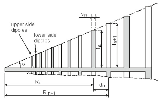
Figure 1.
Schematic view of the log-periodic dipole antenna with a criss-cross feeder line. Dipoles lying on the upper side of the substrate are illustrated with a darker shade.
The LPDA antennas are very useful in practical applications, but they are not without their disadvantages, which should be noted herein. To obtain good periodic performance, the antenna needs to have many dipoles, which increases the size of the structure. For some applications, to reduce the overall dimension of the antenna, meandered dipoles were proposed to reduce dipole length [7], but the most popular design decision is to truncate the array. Such an approach allows us to miniaturize the overall dimensions of the antenna, but such antennas are not frequency-independent due to the limitation in their bandwidth.
In this work, a new approach for LPDA antenna design process is proposed. The novelty of the proposed antenna lies in modifying the lengths of the smallest dipoles. This paper compares the performance of an LPDA antenna designed according to well-accepted rules against the performance of the newly modified antenna.
2. General Principles of LPDA Antenna
The LPDA structure is characterized by its periodic property in the logarithm of frequency. The dimensions of the elements are scaled by scaling constant (τ). In fact, all geometrical dimensions of dipoles are scaled by τ from element to element [8,9].
In addition, the spacing factor (σ) should also be taken into account as a second parameter.
where
- ln—the half of the length of the nth dipole (total length of the nth dipole is Ln = 2 ln),
- Rn—distance from the apex to the nth element,
- sn—width of the nth dipole,
- dn—distance between the nth and (n + 1)th elements.
With the above relationships, LPDA antennas have periodic properties in the logarithm of frequency in accordance with the scaling constant.
In the log-periodic dipole array with its geometrical properties defined by (1)–(2), the dipole ends are laid along two lines. Each line has a virtual apex in the coordinate origin and is inclined at an angle of α [8,10]:
The available literature accurately describes a step by step procedure for designing an LPDA antenna. Generally speaking, only the two factors τ (1) and σ (2) need to be considered when designing an LPDA antenna.
3. Reference-Truncated LPDA Antenna
With an infinite structure, one could achieve an ideal frequency-independent antenna. However, in practical applications, the infinite structure is often truncated, therefore limiting the number of available dipoles. This means that the structure starts with any small dipole and stops at the largest one. Such a structure radiates most of the energy through a limited number of adjacent elements. By its nature, the truncated antenna has limited bandwidth. The highest operating frequency occurs when the shortest dipole is nearly λ/2, and the lowest frequency is determined by the λ/2 length of the longest element.
The investigation of truncation effects was discussed in the literature [9,11,12]. Carrel [9] showed that the elements shorter than the resonating dipoles were important for small values of τ due to remarkable degradation of gain and input impedance. Karoui et al. investigated the number of dipoles in the function of τ, showing that, depending on the bandwidth, the optimum number of dipoles can be as little as 16 for a relatively broad frequency range and as much as 40 for broader bands [12].
A significant number of practical calculations for the total number of dipoles were proposed by De Vito et al. [13], where the number of all dipoles depends on the number of resonating dipoles in the active region. The miniaturization of the array can be achieved when the scaling constant (1) is small, but, on the other hand, the small value of τ results in reduced average gain [8,10].
In this work, the LPDA microstrip antenna has been designed and developed with 12 dipoles, printed on the top and bottom sides of the substrate. This antenna has been designed according to the scale Formulas (1)–(2), with a value of τ = 0.79 and σ = 0.153. Such an antenna, presented in Figure 1, will be treated as the reference antenna, and is the first antenna version developed for comparison with the modified antenna, which has been elaborated upon in the next chapter. The antenna was based on the dielectric substrate FR-4. Values of its electrical properties depend of frequency and they are as follow: at 1 GHz ε = 4.4, tan δ = 0.005; at 10 GHz, ε = 4.3, tan δ = 0.025; at 18 GHz, ε = 4.25, tan δ = 0.02. The substrate is 1.5 mm thick, and the total length of the longest dipole is L12 = 134 mm.
The simulated and measured VSWR of this reference LPDA antenna are presented in Figure 2.
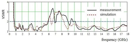
Figure 2.
Simulated and measured VSWR of the reference LPDA antenna.
Accepting VSWR = 2 as the maximum threshold, the reference LPDA antenna operates in a frequency range of 760 MHz to 6 GHz. The measured value coincides relatively closely with the simulation. For the higher frequency, this value can also be calculated analytically based on the length of the shortest dipole. The wavelength λmin can be determined as follows:
and the highest cutoff frequency fmax can be determined from the relationship:
where: εef – effective dielectric constant, according to [14,15].
The length of 1st dipole is L1 = 5.012 mm, and using (6), the upper frequency cutoff is approximately fmax = 8.7 GHz. However, for the reference antenna, the upper frequency value (in both simulations and measurements), as illustrated in Figure 2, is approx. 6 GHz—a less favorable result. A real reference antenna value of fmax is a bit lower than the theoretical value, as predicted with the relationship (6). The existing divergence between the analytical assessment of the value (using (6)) and simulation/measurement is due to the simplicity of the Equation (6), which was developed for microstrip antennas with simple shapes, without other adjacent dipoles. Smith [16] proposed experimental relationships for assessing fmax, but these equations can only be used when the parameter τ is high enough, i.e., τ > 0.95, which is significantly higher than the value accepted in the work (τ = 0.79).
4. LPDA with Modified Truncation
The main goal of this work is to increase the upper frequency range without increasing the footprint of the antenna. To obtain better matching properties of the LPDA antenna with truncated structure in higher frequencies, we propose to shorten the first few dipoles. In this case, the rule of scaling all dipoles with the same scaling constant (τ) will not apply, as the value τ will be different for shorter dipoles. The same can be said for the electrical influence of the first few dipoles on the remaining dipoles in the structure. To analyze this problem, the well-accepted concept of active regions may be useful to interpret energy conveyed along the LPDA [16].
According to the concept of active regions, the LPDA structure is viewed as if it were composed of three separate regions: the transmission-line region, the active region, and the reflection region [16]. In the transmission region, the dipole lengths are shorter than resonating lengths, and the impedance of this part of the antenna can be treated as capacitive. In the active region, the dipole lengths are comparable to λ/2, and these dipoles are responsible for radiating energy. Because of the resistive component of impedance in the resonance, a significant part of conveyed energy is decayed. In the third region, dipole lengths are greater than λ/2 and, in addition, they are supplied by a small amount of energy. Taking into account this concept of conveying energy along the antenna, in the first step of the analysis there is a need to interpret the change of impedance when the few shorter dipoles are completely removed (creating a truncated structure), as presented in Figure 1. Therein, one can observe a so-called gap region (without dipoles) between the first existing dipole and coordinate origin. In fact, non-complete structures, such as the one presented in Figure 1, are often used in LPDA antenna design, as they allow to reduce its overall dimensions. However, in a truncated structure, a range of higher frequencies does not appear in the transmission-line region and the input impedance has a resistive value, resulting in deterioration of the matching.
The question remains regarding how many dipoles can be shortened and which shortening function can guarantee the best matching condition. Nevertheless, the issue of the shortening function is still relevant for matching.
First of all, there is a need to decide how many dipoles must be shortened. In the work, three dipoles were additionally shortened, making up 25% of the total number of antenna elements. This guarantees that the remaining number of elements (remaining dipoles) protect the scaling factor of τ = 0.79. The first, intuitive approach, is to shorten the dipoles using a linear shortening function, as it is presented in Figure 3. In fact, such a simple attempt is not optimal from the matching point of view.
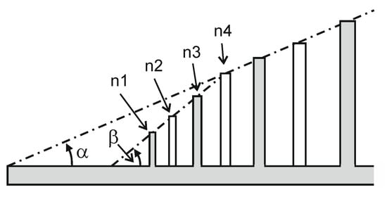
Figure 3.
Schematic view of the PLDA antenna with the first three dipoles linearly shortened (not optimal); n1, n2, n3, n4 are element numbers.
For the optimized shortening technique, the shortening function is an important task. In the simplest case, presented in Figure 3, the ends of the three first elements lie along the line inclined at angle β. This bigger angle β results in a lower value of τ (=τ2). For such linear shortening, the values of τ for the first seven dipoles are presented in Figure 4. One can notice that values for elements 4–12 are equal to τ = 0.79, while for elements of a lower number, τ has a lower value.
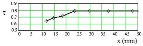
Figure 4.
Values of scaling constants for the first seven dipoles of an antenna with simple linear shortened elements; x—distance from the apex.
Taking into account that the matching condition with linear shortening depends also on the value of angle β the electrical properties of the whole antenna can be even worse. This is because the presence of two angles (α and β) in one structure is against the log-periodic rule. Nevertheless, it is possible to find a shortening function which can be considered optimal for the purposes of matching.
The optimal shortening function can be found, but not by analyzing the lengths of elements (according to (1)), as is presented in the literature. Rather, it is necessary to take into consideration differences between shortened dipole lengths. The proposed ratio factor (τΔ) can be defined as follows:
where
For the structure with an infinite number of dipoles, the ratio factor is equal to the scaling constant.
Equation (9) can be easy proved by substituting and into (8) and (7). Because of relationship (9) the log periodic properties of the structure can be protected using also parameter τΔ. The advantage of proposed ratio factor can be seen when the structure has been truncated. Value of proposed parameter (τΔ) is determined basing on three neighboring dipoles—(n − 1)th, nth and (n + 1)th, while in conventional LPDA structure the scaling constant (τ) takes into account only two elements i.e., nth and (n + 1)th according to (1). With (7) it is possible to optimize lengths of the shortest dipoles.
We experimentally found that a better matching condition can be obtained when the ratio factor for the three shortened elements is linear. With this requirement in mind, the dipole lengths for the design with modified truncation were calculated using Equation (7) and are presented in Table 1. This table also includes dipole lengths for the reference truncated antenna, as discussed in Section 3.

Table 1.
Dipole lengths.
In Figure 5, values of τΔ were depicted for both antennas: for proposed shortening (antenna with modified truncation), in Figure 5a, and for the reference truncated antenna, in Figure 5b.
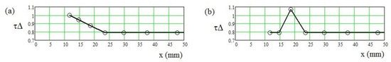
Figure 5.
Values of ratio factor: (a) for proposed shortening, (b) for comparison, for the reference truncated antenna, presented in Figure 3.
The function of the ratio factor for the proposed design is presented in Figure 5a. For comparison, in Figure 5b, values of τΔ have also been presented for the structure shown in Figure 3, i.e., with linear dipole shortening. The introduced parameter τΔ (8) allows us to demonstrate how gentle the dipole shortenings are. In the case of linear shortening (as presented in Figure 3), due to the ratio factor, the significant jump in the function of τΔ (Figure 5b) can be identified.
Considering that the introduced ratio factor in (7) is a very useful parameter, the proposed technique of shortening the first few elements may be used to optimize dipole lengths based on this ratio factor. The lengths of elements have been calculated based on Equation (7), with a linear function of τΔ. The iterative technique should be adopted for calculation, as lengths of lower-numbered elements depend on adjacent elements. This technique was introduced to improve the matching of the antenna. In the proposed model, the lengths of the first dipoles (the three first elements, in this work) were shortened in compliance with the rule of proposed function of τΔ, as presented in Figure 6.
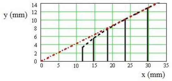
Figure 6.
Lengths of shortened dipoles in the modified antenna structure. The red dotted line shows the line from Figure 1 with the angle of α.
In Figure 6, the lengths of the first five dipoles have been presented. Distance x identifies the dipole positions along the antenna. For this case, the values of parameter τ were shown in Figure 7.
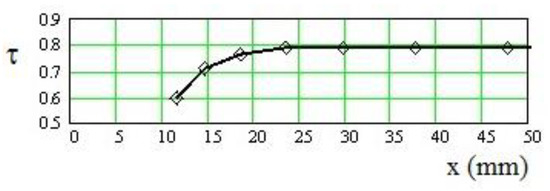
Figure 7.
Values of scaling constant for the proposed antenna structure with optimized shortened elements.
Comparing values of τ for an antenna with linearly shortened elements (simplest case) (Figure 4) and an antenna in which dipole geometry is based on the ratio factor (Figure 7), one can notice that the proposed method results in a smoother curve of dipole lengths. An LPDA antenna has been designed and developed using the proposed technique, and a view of the manufactured antenna is depicted in Figure 8. The value of VSWR is presented in Figure 9.
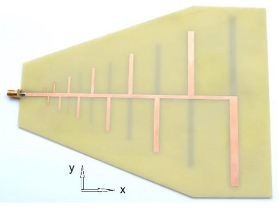
Figure 8.
Illustration of the manufactured, proposed LPDA antenna.
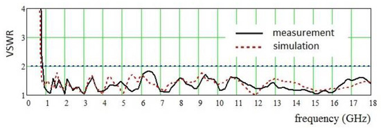
Figure 9.
Simulated and measured VSWR of the proposed LPDA antenna with first three dipoles shortened using the proposed method.
The LPDA antenna with the first three shortened dipoles shows good matching properties, from 760 MHz up to a frequency of 18 GHz. The simulated results match with the measured data.
The enlarged range for higher frequencies presented in Figure 9, despite the truncated structure, is due to the optimal dipole shortening of the shortest dipoles. Such an optimal shortening function was obtained using the ratio factor. It should be also emphasized that the conventional scaling constant allows us to calculate the length of any dipole based on the length of one neighboring dipole, according to Equation (1). The proposed ratio factor takes into account two neighboring dipoles—one longer and one shorter than the analyzed dipole.
It also worth noting that such a good value of VSWR was obtained with a FR-4 substrate, even though this substrate is typically not recommended for higher frequencies. We decided to investigate this material anyway, considering that many laboratories use this dielectric substrate.
Figure 10 and Figure 11 report the frequency relationship of the directivity and gain. Gain was measured according to the ANSI/IEEE standard. The simulated directivity and measured gain of the proposed antenna with modified first three dipoles are presented in Figure 10. A comparison of the measured gain of the proposed modified antenna and reference antenna is shown in Figure 11.
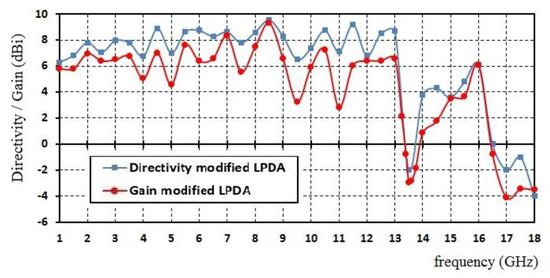
Figure 10.
Simulated directivity and measured gain of the proposed antenna.
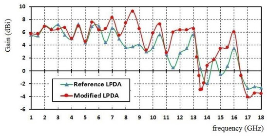
Figure 11.
Comparison of the measured gains of the reference and proposed antennas.
In this work, directivity and gain are presented in Figure 10 and Figure 11, with reference to direction θ = 90°. This allows us to reveal the directivity or non-directivity of the antenna at different frequencies. Figure 10 shows that, in frequencies higher than 13 GHz, both directivity and gain are reduced. This means that such a structure is more akin to an omni-directional antenna. On the other hand, when directivity has a negative value (above 16.5 GHz for discussed antennas), the antenna radiates significantly in different directions to θ = 90°. In fact, a similar tendency for LPDA antennas at high frequencies was reported in [17,18].
A comparison of measured gains of the reference and proposed antennas is presented in Figure 11.
Figure 11 shows that the gains of reference and proposed antennas have a similar tendency at frequencies below 6 GHz. In this frequency range, VSWR values of both antennas are lower than 2 (see also Figure 2). At higher frequencies, the proposed antenna exhibits better gain. Obtained values show that modification of shorter dipole lengths in truncated LPDA antennas yields better antenna properties.
The normalized radiation patterns of both antennas (reference and proposed) in the “xy” plane are depicted in Figure 12. Presented diagrams refer to three representative frequencies: 5 GHz (frequency of good matching for both antennas), 7 GHz (with VSWR higher than 2 for the reference antenna), and 16 GHz (range of higher frequencies).
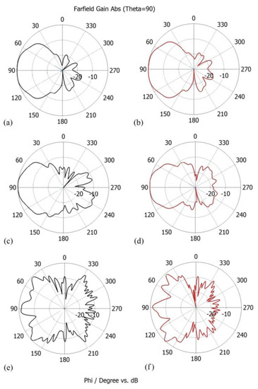
Figure 12.
Normalized radiation patterns of reference and proposed antennas in the “xy” plane; at 5 GHz: (a) reference, (b) proposed antenna; at 7 GHz: (c) reference, (d) proposed antenna, and at 16 GHz: (e) reference, (f) proposed antenna.
Diagrams in Figure 12a,b show that, at a frequency of 5 GHz, radiation patterns of the reference and proposed antennas are quite similar. However, at 7 GHz and 16 GHz, the proposed antenna with modified dipole lengths has better directional properties.
Table 2 summarizes a comparision of the key features of the proposed antenna with other related work. It can be noticed that the proposed solution provides a novel LPDA antenna design, allowing us to obtain a broad frequency band with shorter overall antenna length.
Table 2.
Comparison with other related work.
5. Conclusions
The aim of this work was to design an LPDA antenna which would be more effective at higher frequencies. The proposed antenna is composed of 12 dipoles based on a FR-4 substrate, with a thickness of 1.5 mm. A new design methodology was presented in the work, based on analyzing the newly introduced parameter, which is the ratio factor. This is a very useful parameter, as it allows us to optimize antenna performance and ensures good return loss. Using the proposed technique, the designed and manufactured antenna operates at a frequency range of 760 MHz to 18 GHz. It was possible to obtain such good performance by shortening the first three dipoles with the optimization technique described in the work. The proposed antenna, despite its truncated structure, can be treated as a frequency-independent antenna in the upper-frequency range.
Author Contributions
Conceptualization, R.K., M.C., D.L.; methodology, R.K., D.L.; Software, M.C., D.L.; validation, M.C., D.L.; Formal analysis, R.K., M.C.; Writing—original draft preparation, R.K., M.C.; writing—review and editing, M.C., D.L. All authors have read and agreed to the published version of the manuscript.
Funding
This research received no external funding.
Conflicts of Interest
The authors declare no conflict of interest.
References
- Haykin, S.; Thomson, D.J.; Reed, J.H. Spectrum sensing for cognitive radio. Proc. IEEE 2009, 97, 849–877. [Google Scholar] [CrossRef]
- Chen, L.; Hong, J.; Amin, M. A twelve-ports dual-polarized MIMO log-periodic dipole array antenna for UWB applications. Radioengineering 2019, 28, 68–73. [Google Scholar] [CrossRef]
- Liang, J.J.; Hong, J.S.; Zhao, J.B.; Wu, W. Dual-band dual-polarized compact log-periodic dipole array for MIMO WLAN applications. IEEE Antennas Wirel. Propag. Lett. 2015, 14, 751–754. [Google Scholar] [CrossRef]
- ICNIRP guidelines for limiting exposure to time-varying electric, magnetic, and electromagnetic fields (up to 300 GHz). In Health Physics; 1974; Volume 4, pp. 494–522. Available online: https://www.icnirp.org/cms/upload/publications/ICNIRPrfgdl2020.pdf (accessed on 13 August 2020).
- DuHamel, R.H.; Isbell, D.E. Broadband logarithmically periodic antenna structures. IRE Nat. Conv. Record 1957, 5, 119–128. [Google Scholar]
- Isbell, D.E. Log-periodic dipole arrays. IRE Trans. Antennas Propagat. 1960, 8, 260–267. [Google Scholar] [CrossRef]
- Trinh-Van, S.; Kwon, O.H.; Jung, E.; Park, J.; Yu, B.; Kim, K.; Seo, J.; Hwang, K.C. A low-profile high-gain and wideband log-periodic meandered dipole array antenna with a cascaded multi-section artificial magnetic conductor structure. Sensors 2019, 19, 4404. [Google Scholar] [CrossRef] [PubMed]
- Balanis, C.A. Antenna Theory: Analysis and Design; John Wiley & Sons: New York, NY, USA, 1996. [Google Scholar]
- Carell, R.L. Analysis and Design of the Log-Periodic Dipole Antenna. Ph.D. Thesis, Electrical Engineering Department, University of Illinois, Champaign and Urbana, IL, USA, 1961. [Google Scholar]
- Miligan, T.A. Modern Antenna Design; John Wiley & Sons, Inc.: Hoboken, NJ, USA, 2005. [Google Scholar]
- Hall, P.S. Bandwidth limitations of log-periodic microstrip patch antenna arrays. Electron. Lett. 1984, 20, 437–438. [Google Scholar] [CrossRef]
- Karoui, S.; Skima, A.; Ghariani, H.; Samet, M. Study of log-periodic antenna with printed dipole. In Proceedings of the Fourth International Multi-Conference on Systems, Signals & Devices, Hammamet, Tunisia, 19–22 March 2007. [Google Scholar]
- De Vito, G.; Stracca, G.B. Comments on the design of log-periodic dipole antennas. IEEE Trans. Antennas Propag. 1973, 21, 3. [Google Scholar] [CrossRef]
- Bahl, J.; Garg, R. Simple and accurate formulas for a microstrip with finite strip thickness. Proc. IEEE 1977, 65, 11. [Google Scholar] [CrossRef]
- Chen, Z.N.; Chia, M.Y. Broadband Planar Antennas: Design and Applications; John Wiley & Sons: West Sussex, UK, 2006. [Google Scholar]
- Jordan, E.C.; Deschamps, G.A.; Dyson, J.D.; Mayes, P.E. Developments in broadband antennas. IEEE Spectr. 1964, 1, 58–71. [Google Scholar] [CrossRef]
- Product Catalogue, Aaronia AG, Ultra-Broadband LogPer Antennas. Germany. Available online: https://aaronia.com (accessed on 12 August 2020).
- Bozdag, G.; Kustepeli, A. Subsectional tapered fed printed LPDA antenna with a feeding point patch. IEEE Antennas Wirel. Propag. Lett. 2016, 15, 437–440. [Google Scholar] [CrossRef]
- Casula, G.A.; Maxia, P.; Montisci, G.; Mazzarella, G.; Gaudiomonte, F. A printed LPDA fed by a coplanar waweguide for broadband applications. IEEE Antennas Wirel. Propag. Lett. 2013, 12, 1232–1235. [Google Scholar] [CrossRef]


© 2020 by the authors. Licensee MDPI, Basel, Switzerland. This article is an open access article distributed under the terms and conditions of the Creative Commons Attribution (CC BY) license (http://creativecommons.org/licenses/by/4.0/).