Abstract
Moulds for aeronautical applications must fulfil highly demanding requirements, including the geometrical tolerances before and after curing cycles at high temperatures and pressures. The growing availability of thermoplastic materials printed by material extrusion systems requires research to verify the geometrical accuracy after three-dimensional printing processes to assess whether the part can meet the required geometry through milling processes. In this sense, the application of automated techniques to assess quick and reliable measurements is an open point under this promising technology. This work investigates the integration of a 3D vision system using a structured-light 3D scanner, placed onto an industrial robot in an eye-in-hand configuration and synchronized by a computer. The complete system validates an in-house algorithm, which inspects the whole reconstructed part, acquiring several views from different poses, and makes the alignment with the theoretical model of the geometry of big parts manufactured by 3D printing. Moreover, the automation of the validation process for the manufactured parts using contactless detection of the offset-printed material can be used to define milling strategies to achieve the geometric qualifications. The algorithm was tested using several parts printed by the material extrusion of a thermoplastic material based on black polyamide 6 reinforced with short carbon fibres. The complete inspection process was performed in 38 s in the three studied cases. The results assure that more than 95.50% of the evaluated points of each reconstructed point cloud differed by more than one millimetre from the theoretical model.
1. Introduction
Over the last two decades, additive manufacturing (AM) technology, also called three-dimensional (3D) printing, has acquired an important role under manufacturing processes due to its high flexibility for designing complex geometrical parts and the associated reduction in lead time, material waste and manufacturing costs [1,2]. Under AM processes, the part is created layer by layer from a model generated by computer-aided design (CAD) software [2]. Hence, compared to conventional machining processes, which remove material based on prism-shaped blocks, the AM processes consume the required material defined in the CAD model, including some offset material in the outer perimeters that must be milled to achieve the required geometrical dimensions.
One of the most promising AM technology categories defined in the ISO/ASTM 52900:2021 [3] standard is the so-called material extrusion (MEX) method by means of filament or pellet material fusion [4,5]. The underlying reasons are the simplicity, relatively low cost and the wide diversity of usable thermoplastic polymers [6,7,8]. However, some of the drawbacks include shrinking and low dimensional accuracy, among others [9]. These issues are affected by parameters like the selected thermoplastic material, the features of the material extrusion machine and the printing strategies. In fact, low dimensional accuracy depends on the nozzle dimensions, the layer height and the printing speed [10,11], which can generate irregular surfaces that must be machined to achieve the required geometrical accuracy. This drawback has been more noticeable in the last ten years because researchers have increased the deposition feed rate [12,13,14], developing bigger extrusion systems able to print larger parts [15]. These systems with a high deposition feed rate are being studied for manufacturing large-sized moulds for different sectors, i.e., aeronautical, automotive or wind sectors [16,17]. One of the challenges is related to the production of manufactured goods of high quality. Some researchers focus their works on the optimization of the process parameters during the printing process by means of data-driven predictive models to improve the quality of the part [18]. Another alternative focused on the improvement of the printing process is based on the introduction of image processing techniques to detect defects during the additive manufacturing process with the aim to save money and time [9]. Additionally, other researchers are focused on improving the dimensional quality of the part after the printing process [19]. This strategy requires quality inspection systems to ensure that the part meets the geometrical specification via visual inspection or advanced techniques such as computed tomography (CT) scanning [20] or X-ray inspection, which are typically used after post-processing processes [21]. Although there are some reviews concerning quality inspection systems, due to the importance of delivering high-quality products in manufacturing [22,23], agricultural [24] and aerospace applications [25,26,27], few research papers have focused on the inspection of moulds after being printed by material extrusion systems.
In this research paper, an automatized process to assess the quality of large parts after a printing process via material extrusion is proposed. The whole automated process comprises the integration of a 3D vision system into an industrial robot. The objective is to include it in a full-hybrid manufacturing system composed of three interchangeable modules using an automatic tool changer. The considered interchangeable modules are an AM system, an inspection system and a machining system. This article details the development of an automated in-house algorithm for digitally reconstructing large, printed parts for the aeronautical sector, aligning the printed part with the theoretically designed CAD part model and comparing them for dimensional validation. The results of this algorithm will enable the machining process on the basis of actual data and not just theoretical data.
In addition to the introduction, this paper is divided into four main sections. Section 2 includes the related works investigating the state of the art considering the dimensional evaluation of large parts manufactured by material extrusion. Section 3 describes the methodology, including the experimental equipment and the data collection for reconstructing the large piece. It also describes in detail the implemented algorithm to assess the dimensional accuracy of the manufactured part in contrast to the theoretically designed CAD model of the part. Section 4 describes the results of the automated inspection process in the selected mould following the methods and algorithms described in Section 3. Finally, in Section 5, the conclusions and future work are presented.
2. Related Work
To meet geometrical specifications, an accurate machining process is required. The aim for high-quality tolerances, one of the challenges for machining parts is related to the initial positioning of the part considering a global reference coordinate system. This has been identified in processes such as casting or forging, causing part rejections due to incorrect reference surfaces or features affected by the incorrect positioning [28]. To minimize those problems, some researchers have investigated the automatic alignment of parts, taking advantages of mobile contact-based coordinate measuring systems (CMMs). Moreover, until the end of the last century, the problem of aligning a CAD model with a workpiece was focused on the localization of the part in the workspace, with very little attention paid to the envelopment problem, that is, to solve whether a specific workpiece with unfinished surfaces has enough material to be removed during the machining process [29]. In this sense, some researchers have focused on the self-localization and referencing of the part within the robot coordination system to determine the “zero workpiece” under a more complex framework [23]. Some of the literature is focused on solving the mathematical problem of surface alignment considering the final geometry with the aim of eliminating problems due to a lack of material [30,31,32]. Nevertheless, the characteristics of the 3D-printed parts complicate the selection of a CMM, entailing the selection of a device able to digitalize the complete irregular shape using a contactless method. However, other emerging 3D scanning techniques based on laser triangulation or structured light can be used to reconstruct physical objects [33]. Table 1 summarizes the comparison of several aspects such as flexibility, process time and advantages and disadvantages between the most current inspection techniques, using a qualitative manner based on the literature [34,35,36].

Table 1.
Comparison between most relevant inspection systems.
Systems based on laser profiling or triangulation can generate a full 3D point cloud of the part surface by synchronized sweeps of the laser beam [37,38]. The need to move the system to achieve the full 3D point cloud makes the systems slower and less suitable for automating the process, but they can be a suitable solution when the part is moving on a conveyor. On the contrary, 3D scanners based on the projection of a series of patterns generate a point cloud with the part geometry giving the position of the scene referenced in system coordinates without the need for sweeps. In addition, structured-light scanners are systems that project known coded light patterns and generate a dense point cloud [39]. Moreover, another advantage of this type of 3D scanner lies in the flexibility of automation and the quick response to obtain the reconstructed surfaces. Hence, these kinds of systems are widely used in industrial applications [25]. Considering that the parts to be inspected in the use case could be in different forms, shapes and sizes, the most suitable technology to use is the 3D scanner based on pattern series projection, keeping in mind the scalability for future applications.
There is a wide variety of 3D scanners using a structured-light system on the market, each with different characteristics and peculiarities. The selection of one or another sensor has been made, thus far, considering factors such as the properties of the surface to be reconstructed, the required measurement accuracy, the maximum cycle time or the physical limitations of the working space. As a result of this study and considering the accumulated experience for this kind of application, the vision system selected for digitizing the moulds printed by AM is a 3D vision scanner based on structured-light technology.
This work tackles the problem of the localization and alignment of a large part, printed via AM that presents irregular surfaces due to the inherent manufacturing process. The proposed solution is based on an industrial robot and a 3D scanner for inspecting the complete manufactured part. It is noteworthy that the theoretical CAD model and the printed part are quite dissimilar; hence, an intermediate CAD model, a so-called oversized CAD model, must be generated to be used in a preliminary alignment. This article presents the results of this methodology using real printed parts with the aim of being applied using a more automated process in the near future.
3. Materials and Methods
3.1. Experimental Setup
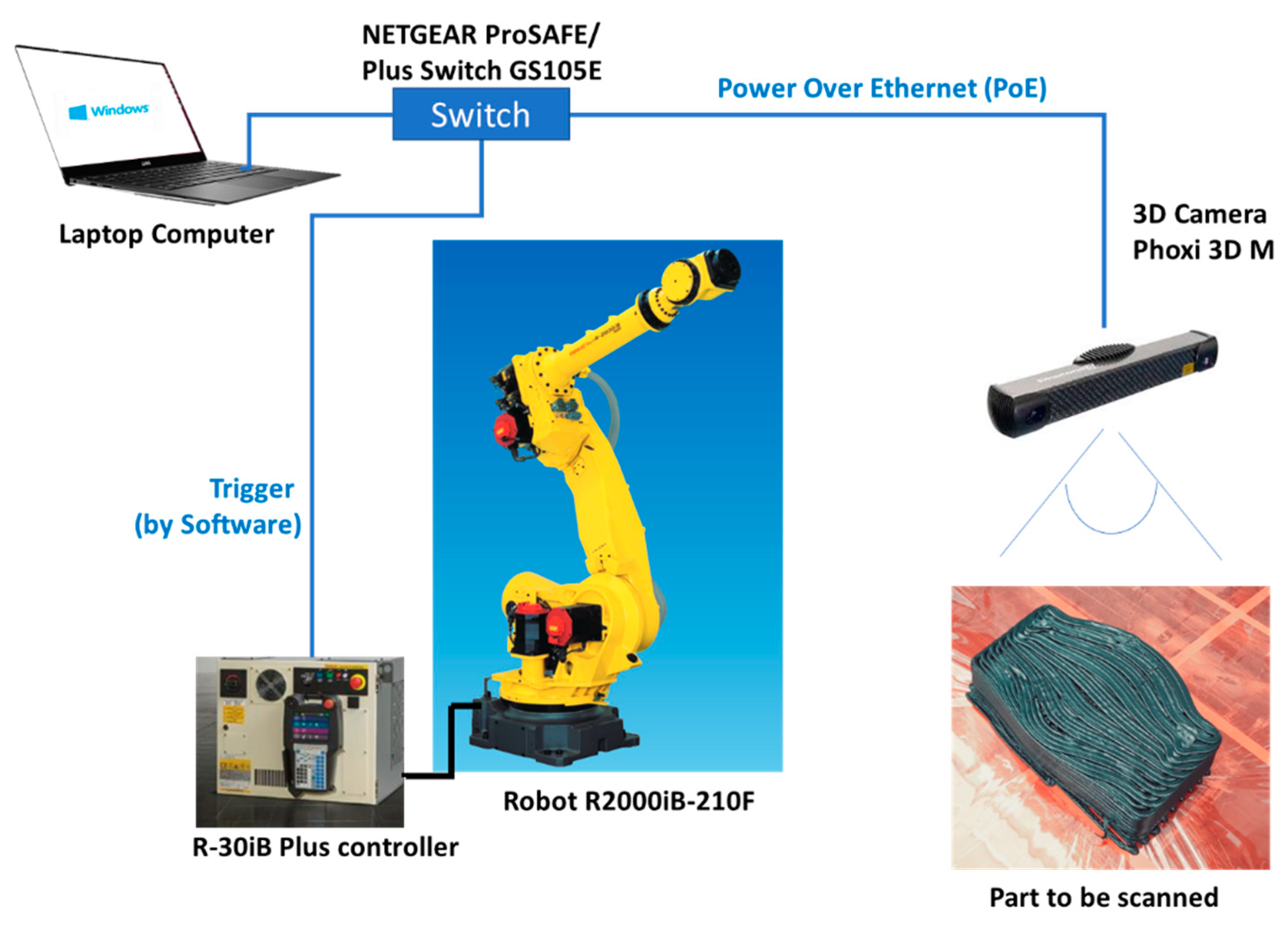
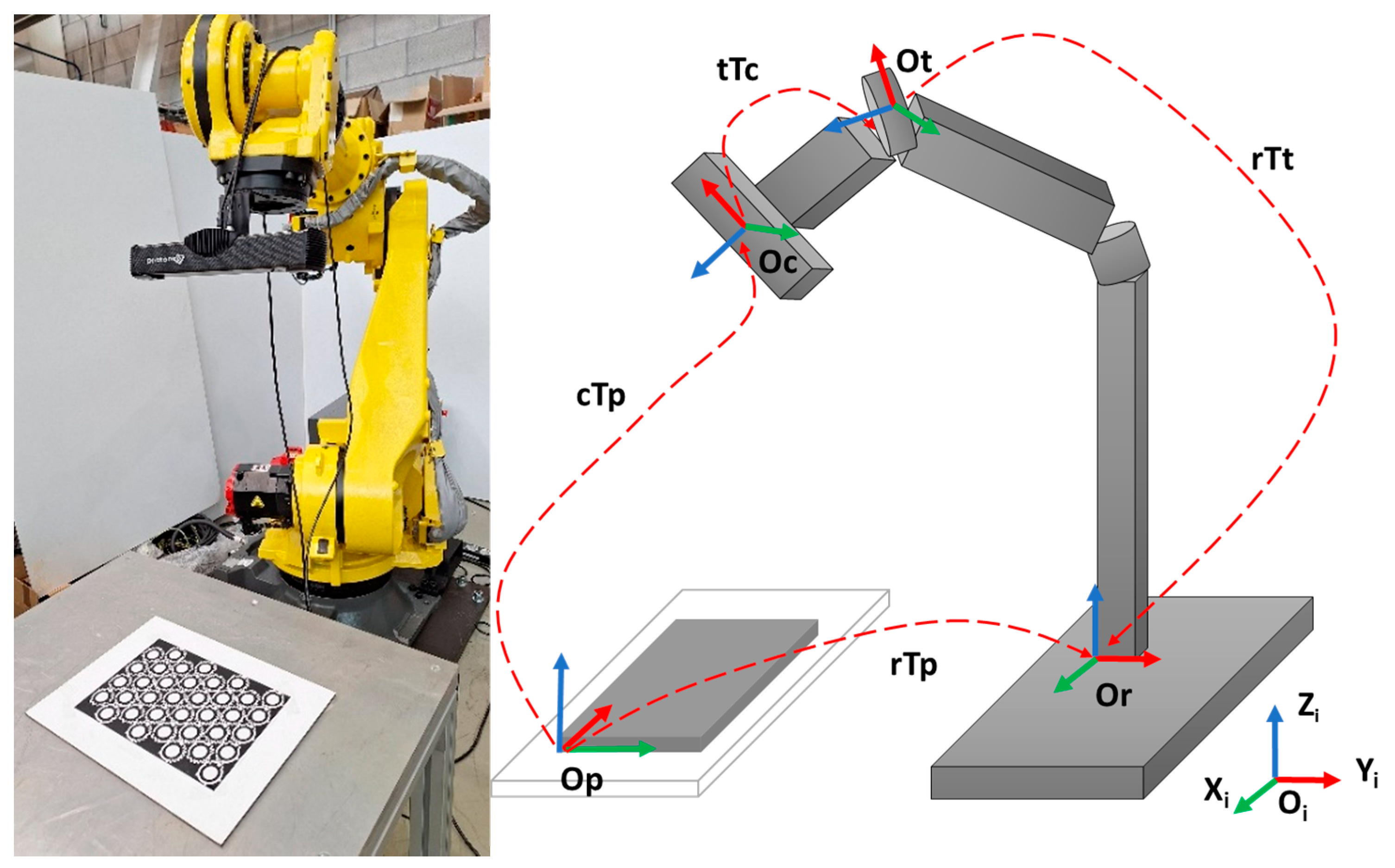
An experimental setup was defined to automatically inspect large parts manufactured by material extrusion. As shown in Figure 1, this setup consisted of a robot R2000iB-210F and its controller R30iB Plus (Fanuc Corporation, Oshino-mura, Japan), a structured-light scanner Phoxi 3D M (Photoneo s.r.o., Bratislava, Slovakia) and a laptop computer (Dell Technologies Inc., Round Rock, USA), which operates to synchronize the movements of the robot with the action to acquire the data of the image via Ethernet communication. Several software packages were also used, such as Open3D library [40] and GOM Inspect software (Carl Zeiss GOM Metrology GmbH, Braunschweig, Germany).
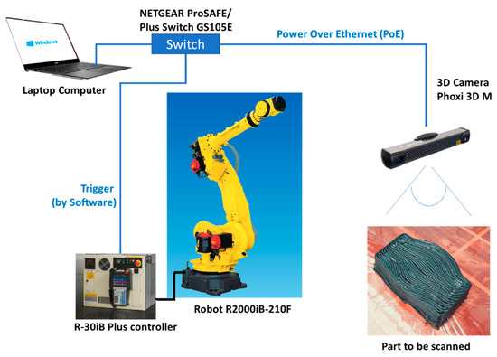
Figure 1.
Experimental setup for quality inspection of big parts.
The 3D scanner presents good versatility as the scanning area is highly variable, depending on the distance to the part. Potentially, the area of interest extends to the reach of the robot, but it was reduced to the size of the table on which parts can be placed (800 mm × 2000 mm). The field of view (FoV) of the camera is 800 mm × 600 mm over a distance of 850 mm, with a resolution of 0.3 mm and with a calibration accuracy of 0.1 mm. This FoV is sufficient to reconstruct the whole piece using the selected robot. The internal parameters such as the shutting exposure of the laser power were fixed considering the type of material, the black colour and the surface brightness. After experimental tests, the duration of the projection of the single pattern was also fixed at 40 ms. Moreover, the scanner captures the 3D point cloud of the view in less than one second.
Before automating the inspection process, a calibration method was used to find the related position between the camera and the robot. The calculated transformation matrix was used to transform the 3D points from the camera coordinate frame to the robot coordinate frame. The Phoxi 3D M camera was placed onto the robot in an eye-in-hand configuration. Photoneo’s camera robot calibration tool [41] was used to calculate the exact position of the device mounted on the moving robot arm with regard to the tool centre point (TCP) of the robot. The tool needed between ten and fifteen scans from different points of view of the marker pattern. Along the process, the scans were saved with the current pose of the TCP of the robot arm. The accuracy of the calibration process depends on the number of scans, the quality of the marker detection and the distance and rotations from the different poses. Knowledge of the exact position of the device on the robot is necessary to transform the position of the scanned object into the coordinate space of the robot. Furthermore, the intrinsic parameters of the camera were used to solve the corresponding relationship between the coordinates of the feature points in both the image and the world coordinates. Knowing the intrinsic matrix of the camera, the extrinsic matrix with respect to the robot-calibration tool was calculated. The camera calibration was performed through the method developed by Zhang Zhengyou [42] as this method is simple to operate with higher precision and lower equipment requirements [43,44]. However, the calibration precision is influenced by the patten of the calibration board. It was demonstrated that an asymmetric circular grid pattern as shown in Figure 2 (left) achieves better accuracy [19].

Figure 2.
Robot–camera calibration process (left). Coordination systems and transformations (right): p: pattern, c: camera, T: transformation, r: robot, t: tool. O: origin of the coordinate systems.
In Figure 2—right, the whole coordinate system is illustrated, including the relationship between the different frames for the calibration process. On the left, the industrial robot, the 3D scanner and the pattern are shown. The origins of the defined coordinate system correspond to Op (pattern coordinate system), Or (robot base coordinate system), Ot (tool coordinate system) and Oc (camera/3D scanner coordinate system). Also, in the figure, the transformation matrix between these coordinate systems is indicated as follows: cTp, the transformation of the pattern in camera frame; rTt, the transformation of the TCP in robot frame; tTc, the transformation of the camera in TCP frame; rTp, the transformation of the pattern in robot frame. The eye-in-hand calibration process solves the A·X = Z·B equation considering that the A (cTp) and B (rTt) matrices are known, while X (tTc) and Z (rTp) must be estimated. The approach of the simultaneous estimation of the hand–eye transformation and the pose of the robot in the world was used [45]. The calibration process solved the equations using different poses and scans and an optimization algorithm of Photoneo’s tool [41]. For this process, 17 images from different poses were acquired obtaining the following calibration matrix (rTp):
The mean reprojection error per camera point corresponded to 0.766571, calculated in pixels.
Once the calibration is performed between the camera and the robot, the location of other objects can be determined in the robot coordinate system, allowing other operations in the future such as machining post-processes.
The MOLDAM additive manufacturing system (Tecnalia, Donostia-San Sebastián, Spain) for thermoplastic material extrusion [46] was used to print the part. The selected part for the evaluation of the hereinafter explained algorithm was printed using black polyamide 6 reinforced with carbon fibres with the parameters identified by Additive Manufacturing System II (AMS II) in previous research [47]. To describe the developed methodology, a part of a complete mould pre-form of an aeronautical mould was selected. The main dimensions of the theoretical CAD model of the piece were 373 mm (width) × 237 mm (depth) × 100 mm (height), as shown in Figure 3 (left). It was printed using a bead size of 8 mm (width) × 4 mm (height) to reduce the manufacturing time but to also maintain a good quality of the bead. A theoretical offset of 8 mm was applied on every face to be milled after inspection (Figure 3–right) with the aim of compensating for any lack of precision during the printing process. The difference in final dimensions of the part after machining must be lower than 0.1 mm according to the end-user requirements.
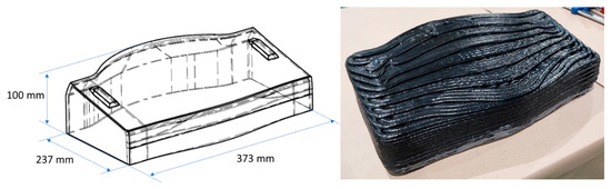
Figure 3.
Designed part. Isometric view of the theoretical CAD model (left). Manufactured part (right).
3.2. Methodology: Automation Inspection Process
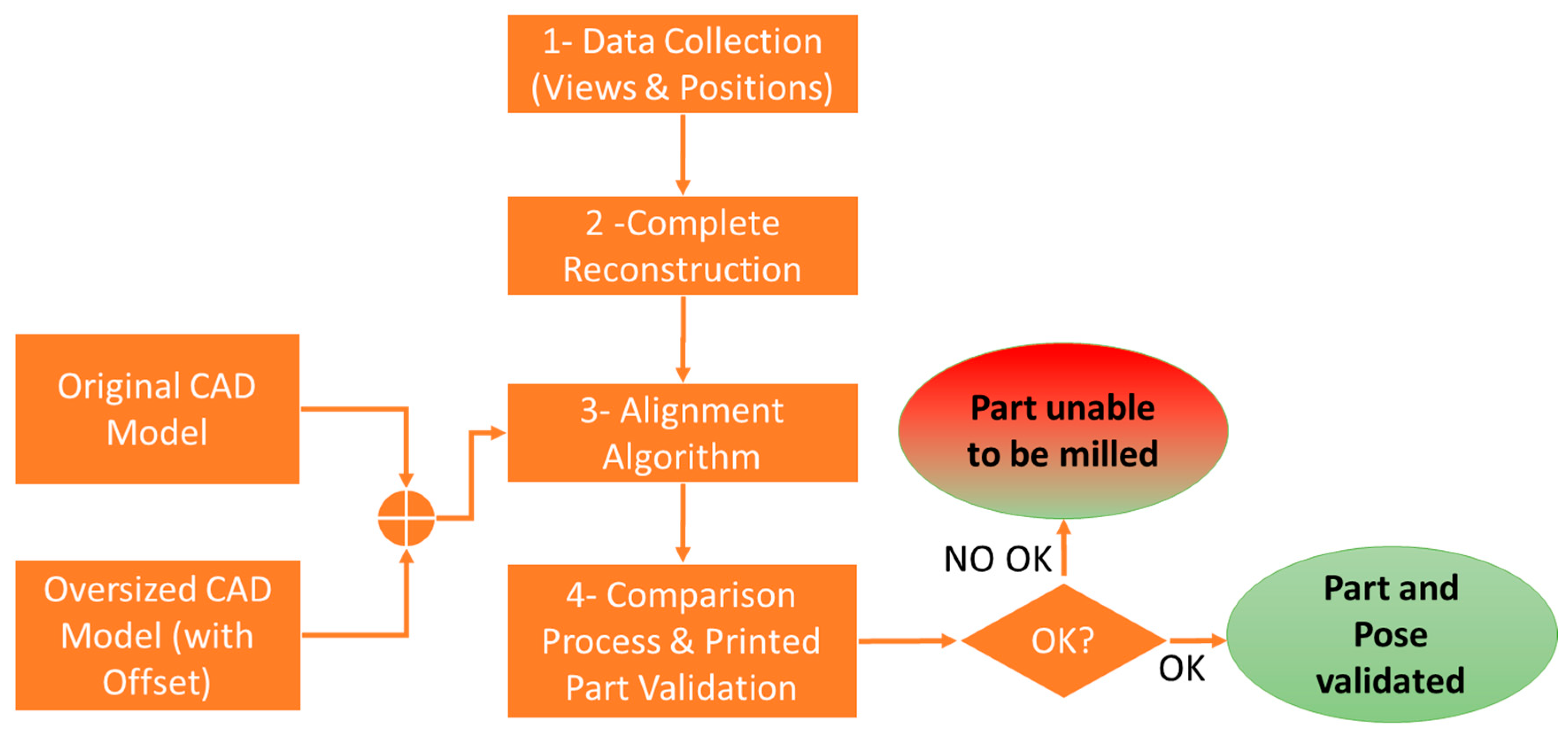
The developed methodology for inspecting these kinds of large parts is summarized in Figure 4. It assumes that the manufactured part is placed on a planar surface and referenced to the table on which it has been printed. Also, the algorithm considers that the offset of the material excess is known. All the stages are detailed hereinafter.

Figure 4.
Workflow of the computer-vision-based framework.
3.2.1. Data Collection
The data collection stage defines the positions to which the robot must be moved to acquire all views needed to reconstruct the complete large part. Firstly, the implementation of the communications between the robot controller and the 3D scanner must be established to synchronize the capture of the different views of the piece and the pose of the robot. This communication was implemented by means of the power-over-Ethernet (PoE) protocol in combination with a trigger signal via Ethernet between the computer and the robot controller. Afterward, a module software was developed to perform the automatic inspection of the complete printed part. To obtain the complete reconstruction of the part, the 3D scanner must be moved around the piece, creating one point cloud in each different pose’s view, saving both the point cloud and the robot pose. The module was programmed in C++ language, integrating the scanner libraries and open-source 3D point cloud processing libraries, such as Open3D library [40].
The automation of the registration of the views captured with the Phoxi 3D M scanner is commanded by the robot following a master–slave communication. Although some researchers have developed a method for autonomously digitalizing whole unknown objects [48], under this specific use case, the scanning distance and the number of views were determined in a first approach via several trials to find the best positions depending on the overall size of the piece. Using this trial-and-error method, the required capture positions of the robots to reconstruct the entire part were precisely known.
The 3D scanner acquires high-resolution points clouds at an acceptable speed for the process, i.e., less than one second. Therefore, the quality of the 3D point cloud obtained by the digitalization of the surface of the part was validated prior to integration into the robotic system. In this case, it was verified that the camera generated point clouds with sufficient quality to make the measurements within the required tolerances of 0.2 mm.
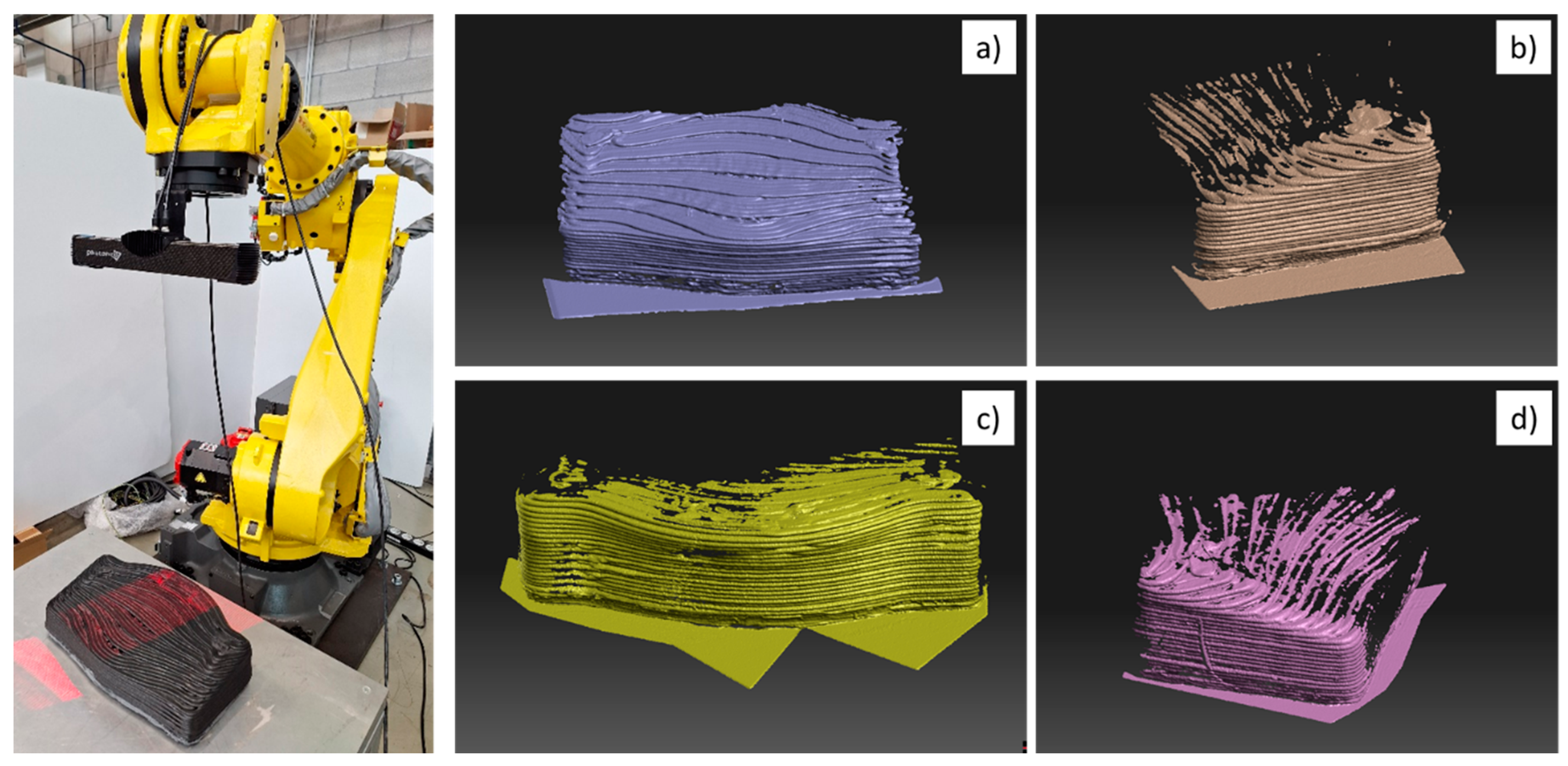
A total of four capture positions were defined after the experimental tests, which were used for parts with similar dimensions. For parts with larger or smaller sizes, more complex geometries or, for higher accuracies, a preliminary study should first be carried out. Figure 5—left shows the moment at which the automatic inspection programme performs one of the captures of the views to complete the 3D reconstruction of the piece. Figure 5 also illustrates the result of the point cloud data collection in the different robot positions prior to completing the reconstruction of the part.
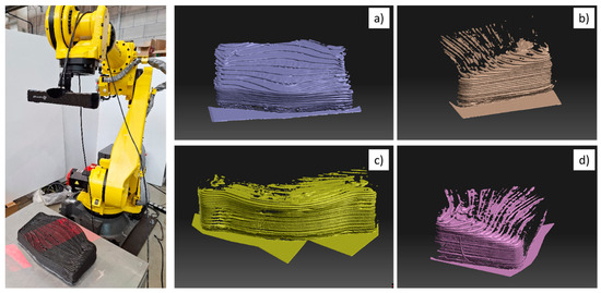
Figure 5.
Left: Robot and 3D scanner placed in an eye-in-hand configuration capturing the image of the part. Acquired views for reconstructing the complete piece. (a) Pose 1—front side; (b) Pose 2—right side; (c) Pose 4—back side; (d) Pose 3—left side.
3.2.2. Complete Reconstruction
After the data collection and view registration process, the next stage comprises the complete 3D reconstruction of the whole piece. The strategy uses the robot poses to automate the alignment of the different views obtained by the camera. Consecutive views include overlapping areas to avoid incomplete information about the part surface. Hence, there are redundant data, matching in two continuous captures.
As the calibration is performed, using the transformation matrix, the positions provided by the camera are converted into positions expressed in robot coordinates. The result of this process is a first positioning of each view, which is adjusted by an iterative closest point (ICP) algorithm. This algorithm is currently employed to minimize the differences between two clouds of points and is the most commonly used iterative algorithm in current 3D alignment [49]. After recording the views and obtaining a single mesh representing the complete part, the coordinates of the mesh points are available in the robot’s reference system. It is noteworthy that, in this process, the algorithm performs five steps:
- Matching of the robot pose and the cloud of points in a position, recording both matrix values.
- Robot and 3D scanner synchronization.
- Point cloud processing to prepare the point cloud, simplify the cloud, delete holes or smooth out the squares among other operations.
- Loading views and aligning them using the ICP algorithm.
- Triangular meshing to convert single individual points into a continuous surface referenced to the robot coordinate system.
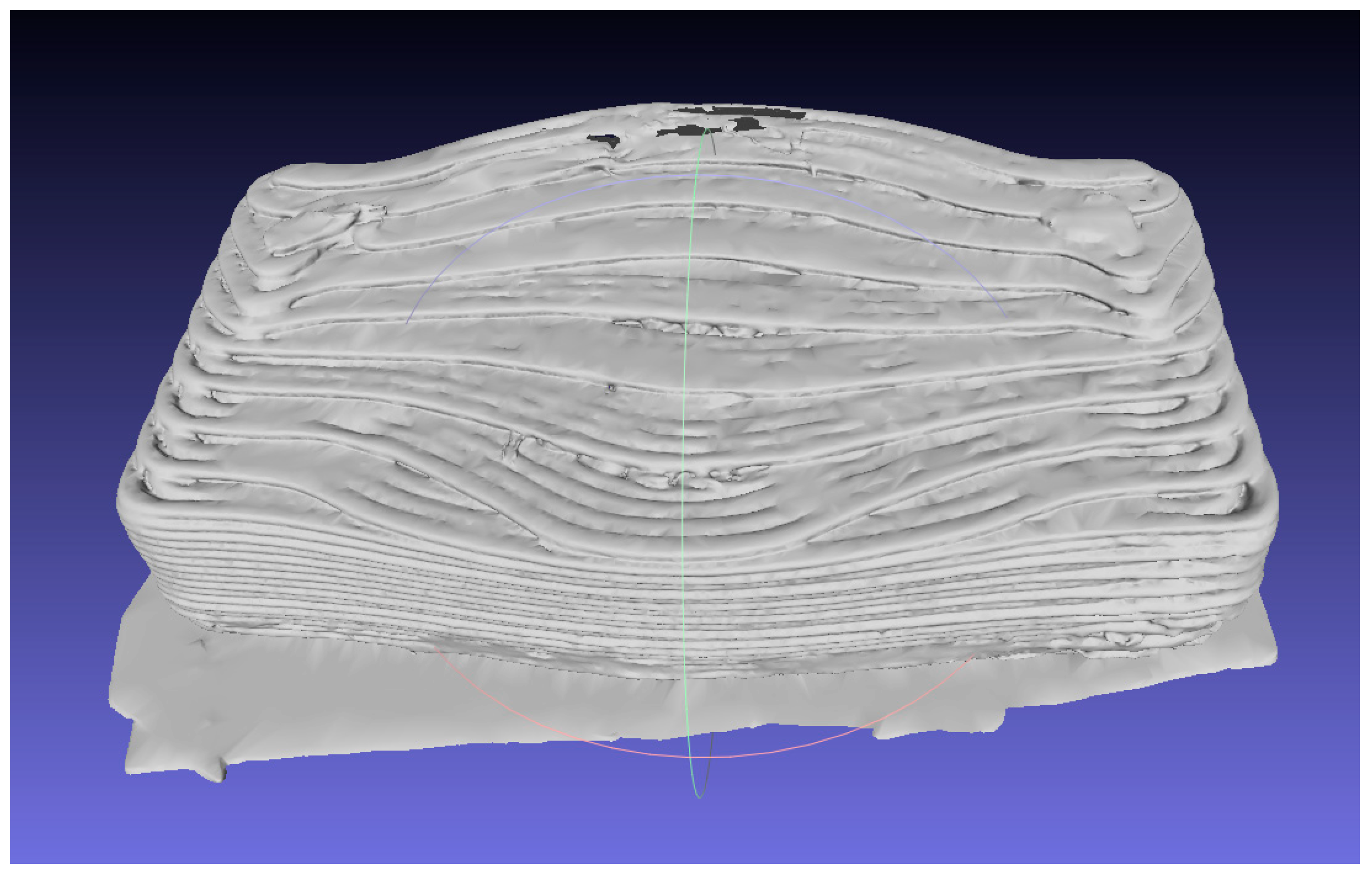
Figure 6 illustrates the result of the point cloud after combining the data collection from the different positions, finishing the complete reconstruction of the part.

Figure 6.
Digitalization of the manufactured part by 3D printing process.
3.2.3. Alignment Algorithm
Once the 3D reconstruction of the piece is completed, the programme executes the alignment of the mesh against the theoretical CAD model of the part and the CAD model generated with the known offset of the excess material, also called as oversized model in this research. This model is used as an auxiliary model to pre-align the manufactured part with the excess material.
During a 3D alignment process of a manufactured part with its theoretical CAD (Figure 7—left), the geometry and dimensions of the manufactured part correspond to those of the CAD. However, in this case, the part was manufactured by a 3D printing system using over-dimensioning with the aim to reduce the effects of a possible lack of material in some areas during the AM process, which influences the subsequent machining process. In addition, its surface was rough and irregular, which significantly hinders the alignment process.

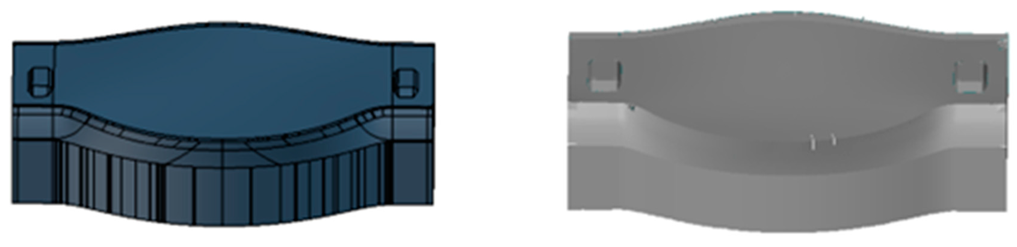
Figure 7.
Theoretical CAD model of the use case (Left). Generated CAD model applying 8 mm oversize (right).
In this context, to facilitate the alignment process of the manufactured 3D part, a strategy was designed to minimize the error in the global alignment of the 3D surface obtained from the reconstruction of the part with the theoretical CAD of the part. The first step in the strategy was to create the CAD model that simulates the part with surplus material (Figure 7—right), so that it better represents the geometry and dimensions of the manufactured part. This oversized CAD model was generated using a scaling function of the GOM Inspect programme. The oversized CAD model included an 8 mm excess all around the volume; therefore, a surplus of 8 mm of material was added to all the faces. To have the same basis reference, this oversized CAD model must be cut by 8 mm on its base, placing the oversized CAD model on the table, to align both CADs symmetrically. This modified CAD model was used to perform the rough alignment so that the digitalized part, also called the reconstructed part, was located with respect to the CAD model with the manufactured surplus offset. The reference in both CAD files, original and oversized, was the same. The alignment process steps are illustrated in Figure 8, in which Tp and Tm represent the transformation matrix of the part and the model with respect to the robot frame, respectively.
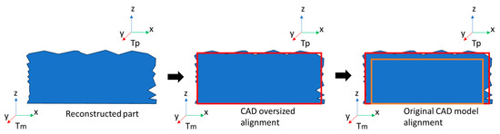
Figure 8.
Alignment process steps. Reconstructed part location (left), oversized CAD model alignment to the reconstructed part (red—centre) and alignment of the original CAD (orange—right) to oversized CAD models (red—right).
As the theoretical CAD and the CAD with the offset are known, the reconstructed part can be aligned after defining several criteria in the alignment algorithm, based on point-to-point measurements between the mesh of the reconstructed part and both CAD files: theoretical and oversized CAD models.
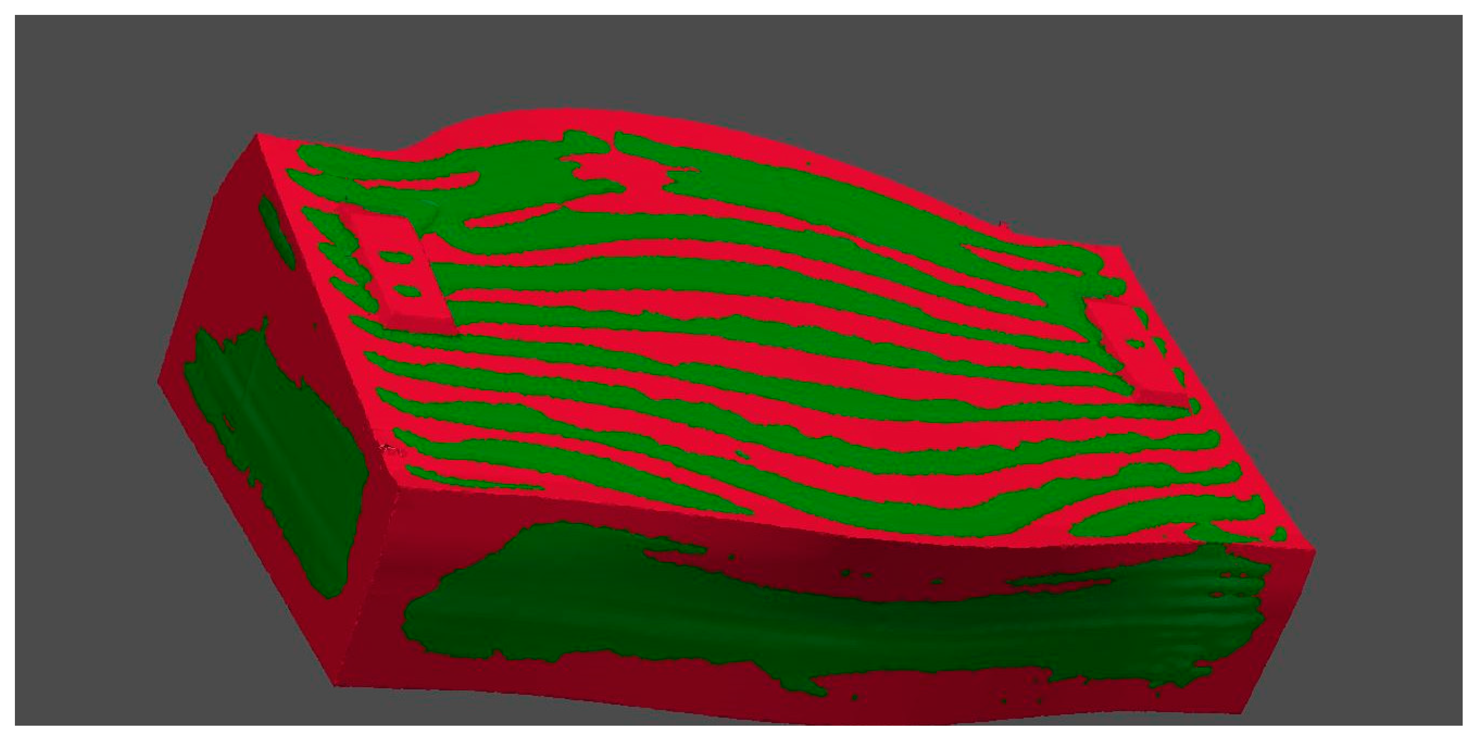
Although the surface of the manufactured part and the oversized CAD model were different, using, firstly, a best fitting algorithm after selecting some characteristic points of the part, a rough alignment was performed. In a subsequent step, an optimization algorithm based on ICP performed a finest alignment minimizing the Euclidean distance error between oversized CAD model points and points of the digitalized part. Figure 9 illustrates the result of the 3D alignment process, in which the red areas correspond to the oversized CAD model, and the green areas show the reconstructed 3D-printed part. As seen in the figure, some areas of the oversized CAD model were out of the 3D-printed part, demonstrating an irregular printing process in some areas such as corners and top-layer changes.

Figure 9.
Result of 3D alignment process. Three-dimensionally printed part (green) and oversized CAD model (red).
3.2.4. Comparison Process and Printed Part Validation
In this process, the reconstructed manufactured part is compared to the theoretical CAD model of the part. The surfaces are compared to evaluate whether the manufactured part can be machined correctly due to the detection of enough surplus material that is potentially machinable. Hence, the computer vision system must measure the dimensions and detect any deformations or defects on the surface.
Part validation is performed by verifying whether the part is dimensionally functional. This means that the surplus over the entire surface of the part meets the requirements specified for the machining process, between 0 and 8 mm.
After studying different methods for measuring the thickness of the surplus over the manufactured part, a method based on the concept of surface comparison (see Figure 10) was selected. Additionally, this method was used to determine whether the manufactured part was suitable for a subsequent machining process. Therefore, the distance between the surface of the reconstructed part and the theoretical CAD value projected from the normal of the CAD surface was calculated to validate whether the surplus volume was sufficient for all the machinable surfaces.
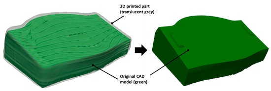
Figure 10.
Original CAD enclosed inside the digitalized printed part (left) and the original CAD (right).
That is, the point-to-point distances projected from the normal of the theoretical CAD surface with respect to reconstructed part are calculated and the manufactured part is determined to be correct if 95% of the evaluated points are at a distance greater than the specified value recommended by the machining process, in this case, more than one mm.
The complexity of the design of this algorithm is because the theoretical CAD of the final part does not “look like” the real part, so a “best fit” of the surfaces used for locating parts in 3D is not enough in this case. The pseudo-code represented in Algorithm 1 summarizes the implementation of the whole 3D reconstruction and alignment process among the theoretical CAD, the oversized CAD and the digitalized manufactured part.
| Algorithm 1 Pseudo-code of the inspection 3D digitalized part alignment | ||
| 1 | : | function DataCollection |
| 2 | : | if (robotConnected) and (camera) then |
| 3 | : | Home Position |
| 4 | : | for posenum loop |
| 5 | : | Go to position |
| 6 | : | Scan |
| 7 | : | Save point cloud and robot pose |
| 8 | : | |
| 9 | : | function CompleteReconstruction |
| 10 | : | load(point_clouds) |
| 11 | : | load (robot_poses) |
| 12 | : | For posenum loop |
| 13 | : | Transformed_p = transform(point_cloud, robot_pose) |
| 14 | : | complete_pointcloud = final_alignment_icp(transformed_p) |
| 15 | : | mesh = generate_mesh (complete_pointcloud) |
| 16 | : | |
| 17 | : | function Alignment |
| 18 | : | load(mesh) |
| 19 | : | load (CAD) |
| 20 | : | CADSurplus = calculate_CADwithSurplus |
| 21 | : | if CADSurplus then |
| 22 | : | best_fit (CADSurplus, mesh) |
| 23 | : | Validation_ok = compare (CAD, mesh) |
| 24 | : | return validation_ok |
| 25 | : | Else |
| 26 | : | return False |
4. Results
As a result of the application of the previously detailed methodology, the process engineer can determine whether a part is valid for machining post-processes. Moreover, as seen in Figure 11, the resulting colour map during the comparison process allows knowledge about the extra thickness in each area. In Table 2, the percentages of the points at different distance ranges are classified, taking into account that the reconstruction comprises 1,994,266 points. The calculation of the percentage of the points inside the point cloud was performed by summing up each point included in the defined ranges (in Table 2) and dividing by the total number of acquired points. As listed in Table 2, 95.50% of the points in the point cloud of the manufactured part 3D reconstruction were more than 1 (one) mm apart from those in the CAD version. The percentage of calculated points under 0 mm corresponded to areas in which the 3D reconstruction identified holes or lack of material on the surface.
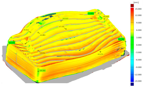
Figure 11.
Comparison between the theoretical CAD model and the reconstructed parts of the printed part—colour map view.
Table 2.
Percentage of acquired points under different ranges.
The described algorithm in this article was executed in 38 s for the presented manufactured part. Table 3 shows the calculated data of each process considering that the process only acquired four views. In this time evaluation, only the robot movement time between poses could be optimized, increasing the robot speed between pose views.
Table 3.
Process time evaluation when four view acquisitions were performed.
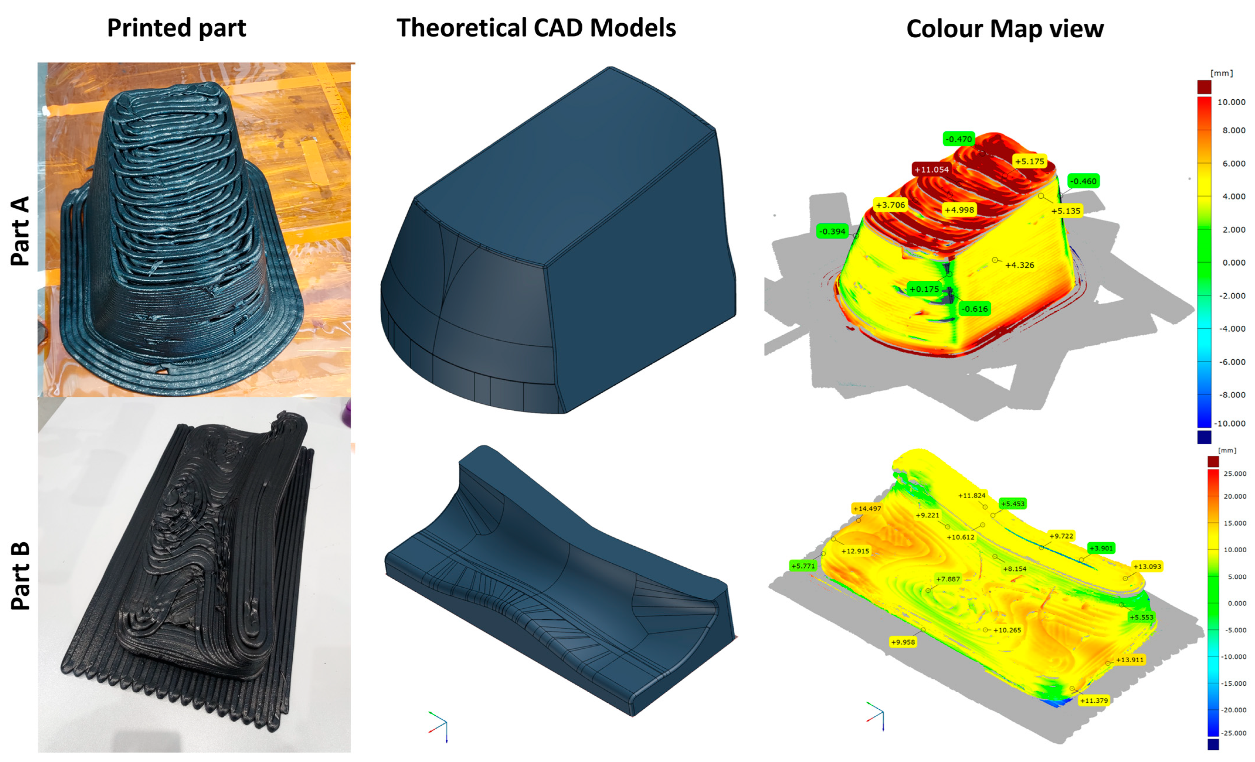
To verify its applicability, the developed methodology was applied to inspect two other parts, A and B, printed using the same process parameters during the manufacturing process. The theoretical maximum dimensions (width × depth × height) of each part were 220 mm × 290 mm × 167 mm and 432 mm × 186 mm × 84 mm, respectively. The theoretical CAD model and the comparison between the CAD and the reconstructed part of the printed parts are shown in Figure 12. Part A was printed without any additional surplus material, whereas Part B was manufactured applying 8 mm of surplus material around the visible faces. The percentage of acquired points over 1 mm from the theoretical CAD models were 96.18% and 97.15%, respectively. The process time was equal to that previously reported since the number of acquired views was four, and the dimensions of the parts were quite similar.
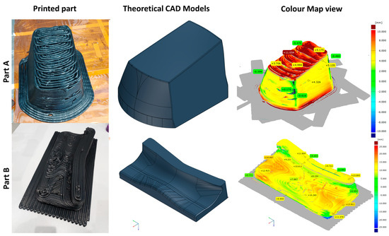
Figure 12.
Printed parts, theoretical CAD models and comparison between the CAD and the reconstructed parts of the printed parts A and B—colour map view.
5. Conclusions and Future Work
In this work, an automatization process to assess the quality of big parts printed by material extrusion is described and validated using a piece of an aeronautical mould preform. Moreover, the same method was used to inspect two more parts printed with the same material and with similar dimensions. The inspection system consisted of an industrial robot in which a 3D camera with structured light was attached in an eye-in-hand configuration. The in-house algorithm used the original CAD model and an oversized CAD model with a predetermined known offset to align and reference the 3D-printed part under the robot coordinates. The algorithm solved the problem of referencing and aligning the 3D-printed part with the theoretical CAD model to determine whether the component met the required tolerances prior to machining post-processes. More than 95% of the points in the cloud differed by more than one mm, validating that the printed parts had enough material to be milled. The aim was the creation of parts with oversized dimensions to compensate for the lack of precision during the additive manufacturing process due to the printing parameters, e.g., bead width and height and process speed.
Once the part is validated, the real reconstruction points can be used to correct or adjust the machining trajectory. Firstly, the machining trajectories could be calculated over the theoretical CAD model. In this case, the machining can be carried out using the same robotic system, changing the tool in a multi-technology system by means of an automatic tool changer. Therefore, the trajectory points are transformed in the same robot coordinate frame. Sharing the same coordinate system, the global process time is reduced as long as manipulation operations are reduced. As the vision system has been calibrated in the robot coordinate frame, the 3D points of the reconstructed part are referenced in the robot. Using all the transformation matrices in this process, the trajectory of the machining process could be corrected and transformed automatically in the robot coordinate frame. Using this scan and plan system, the suitability of a subsequent machining process is determined, based on real and not theoretical data, to reach the correct dimensions of the mould for curing parts onto it, following the requirements of the end user. This methodology can be applied with other 3D-printed parts with similar sizes; although, by increasing the number of views and positions, it can cover bigger parts. The developed inspection solution has been previously applied for other types of materials, such as metals, composites and plastics. The limitations of this methodology are related to the robot’s reach or the maximum process time required for the application. The greater the precision, the greater the quantity of acquisition views and, hence, the greater the total inspection process time. In addition, reflective materials should be avoided. Another limitation could come from space limitations, which could limit the ability to properly perform the view acquisitions.
Author Contributions
The contribution of each author is mentioned here. Conceptualization, J.C.A.-U.; Methodology, R.P.G. and N.A.O.; Software, R.P.G. and N.A.O.; Validation, J.C.A.-U. and A.I.L.P.; Formal analysis, R.P.G. and N.A.O.; Investigation, J.C.A.-U., R.P.G. and N.A.O.; Data curation, R.P.G. and N.A.O.; Writing—original draft, J.C.A.-U., R.P.G. and N.A.O.; Writing—review and editing, J.C.A.-U. and A.I.L.P.; Visualization, R.P.G. and N.A.O.; Supervision, J.C.A.-U. and A.I.L.P. All authors have read and agreed to the published version of the manuscript.
Funding
This research was co-funded by EIT Manufacturing, code 22017 and 23025.
Data Availability Statement
The data presented in this study are available upon request due to privacy restrictions.
Acknowledgments
The work leading to this publication was co-funded by EIT Manufacturing under the code 22017 and 23025. EIT Manufacturing is supported by the European Institute of Innovation and Technology (EIT), a body of the European Union. The views and opinions expressed are, however, those of the author(s) only and do not necessarily reflect those of the European Union or EIT Manufacturing. Neither the European Union nor EIT Manufacturing can be held responsible for them. The authors would like to thank Richard Seddon for his help in reviewing this article.
Conflicts of Interest
The authors declare that they have no known competing financial interests or personal relationships that could have appeared to influence the work reported in this paper.
References
- Tao, Y.; Kong, F.; Li, Z.; Zhang, J.; Zhao, X. A review on voids of 3D printed parts by fused filament fabrication. J. Mater. Res. Technol. 2021, 15, 4860–4879. [Google Scholar] [CrossRef]
- Tofail, S.A.M.; Koumoulos, E.P.; Bandyopadhyay, A.; Bose, S.; O’Donoghue, L.; Charitidis, C. Additive manufacturing: Scientific and technological challenges, market uptake and opportunities. Mater. Today 2018, 21, 22–37. [Google Scholar] [CrossRef]
- UNE-EN ISO/ASTM 52900-21; Additive Manufacturing—General Principles—Fundamentals and Vocabulary. UNE-EN (Una Norma Española Sobre Norma Europea): Madrid, Spain, 2021.
- Dey, A.; Eagle, I.N.R.; Yodo, N. A review on filament materials for fused filament fabrication. J. Manuf. Mater. Process. 2021, 5, 69. [Google Scholar] [CrossRef]
- Pignatelli, F.; Percoco, G. An application- and market-oriented review on large format additive manufacturing, focusing on polymer pellet-based 3D printing. Prog. Addit. Manuf. 2022, 7, 1363–1377. [Google Scholar] [CrossRef]
- Valino, A.D.; Dizon, J.R.C.; Espera, A.H.; Chen, Q.; Messman, J.; Advincula, R.C. Advances in 3D printing of thermoplastic polymer composites and nanocomposites. Prog. Polym. Sci. 2019, 98, 101162. [Google Scholar] [CrossRef]
- Patel, A.; Taufik, M. Extrusion-Based Technology in Additive Manufacturing: A Comprehensive Review. Arab. J. Sci. Eng. 2022, 49, 1309–1342. [Google Scholar] [CrossRef]
- Zhuo, P.; Li, S.; Ashcroft, I.A.; Jones, A.I. Material extrusion additive manufacturing of continuous fibre reinforced polymer matrix composites: A review and outlook. Compos. Part B Eng. 2021, 224, 109143. [Google Scholar] [CrossRef]
- Hammouda, A.B.; Frikha, A.; Koubaa, S.; Mrad, H. Defect detection in additive manufacturing using image processing techniques. Procedia Comput. Sci. 2024, 232, 2157–2166. [Google Scholar] [CrossRef]
- Roschli, A.; Gaul, K.T.; Boulger, A.M.; Post, B.K.; Chesser, P.C.; Love, L.J.; Blue, F.; Borish, M. Designing for Big Area Additive Manufacturing. Addit. Manuf. 2019, 25, 275–285. [Google Scholar] [CrossRef]
- Sola, A. Materials Requirements in Fused Filament Fabrication: A Framework for the Design of Next-Generation 3D Printable Thermoplastics and Composites. Macromol. Mater. Eng. 2022, 307, 2200197. [Google Scholar] [CrossRef]
- Monzón, M.D.; Gibson, I.; Benítez, A.N.; Lorenzo, L.; Hernández, P.M.; Marrero, M.D. Process and material behavior modeling for a new design of micro-additive fused deposition. Int. J. Adv. Manuf. Technol. 2013, 67, 2717–2726. [Google Scholar] [CrossRef]
- Babu, S.S.; Love, L.; Dehoff, R.; Peter, W.; Watkins, T.R.; Pannala, S. Additive manufacturing of materials: Opportunities and challenges. MRS Bull. 2015, 40, 1154–1161. [Google Scholar] [CrossRef]
- Go, J.; Schiffres, S.N.; Stevens, A.G.; Hart, A.J. Rate limits of additive manufacturing by fused filament fabrication and guidelines for high-throughput system design. Addit. Manuf. 2017, 16, 1–11. [Google Scholar] [CrossRef]
- Love, L.J.; Duty, C.E.; Post, B.K.; Lind, R.F.; Lloyd, P.D.; Kunc, V.; Peter, W.H.; Blue, C.A. Breaking Barriers in Polymer Additive Manufacturing. In SAMPE 2015; SAMPE North America: Baltimore, MD, USA, 2015. [Google Scholar]
- Abderrafai, Y.; Diouf-Lewis, A.; Sosa-Rey, F.; Farahani, R.D.; Piccirelli, N.; Lévesque, M.; Therriault, D. Additive manufacturing and characterization of high temperature thermoplastic blends for potential aerospace applications. Compos. Sci. Technol. 2023, 231, 109839. [Google Scholar] [CrossRef]
- Chesser, P.; Post, B.; Roschli, A.; Carnal, C.; Lind, R.; Borish, M.; Love, L. Extrusion control for high quality printing on Big Area Additive Manufacturing (BAAM) systems. Addit. Manuf. 2019, 28, 445–455. [Google Scholar] [CrossRef]
- Li, X.; Zhang, M.; Zhou, M.; Wang, J.; Zhu, W.; Wu, C.; Zhang, X. Qualify assessment for extrusion-based additive manufacturing with 3D scan and machine learning. J. Manuf. Process. 2023, 90, 274–285. [Google Scholar] [CrossRef]
- Tu, Y.; Gong, H.; Hassan, A.; Siadat, A.; Chen, Z. Computer vision-based evaluation of dimensional accuracy for MEAM in new product development. Procedia CIRP 2023, 119, 444–449. [Google Scholar] [CrossRef]
- Mac, G.; Mandal, M.; Rastogi, A.; Gailani, G.; Pearce, H.; Gupta, N. Application of micro-computed tomography for authentication of 3D printed composite parts. Addit. Manuf. Lett. 2022, 3, 100104. [Google Scholar] [CrossRef]
- Kanishka, K.; Acherjee, B. Revolutionizing manufacturing: A comprehensive overview of additive manufacturing processes, materials, developments, and challenges. J. Manuf. Process. 2023, 107, 574–619. [Google Scholar] [CrossRef]
- Babic, M.; Farahani, M.A.; Wuest, T. Image Based Quality Inspection in Smart Manufacturing Systems: A Literature Review. Procedia CIRP 2021, 103, 262–267. [Google Scholar] [CrossRef]
- Lupi, F.; Maffei, A.; Lanzetta, M. CAD-based Autonomous Vision Inspection Systems. Procedia Comput. Sci. 2024, 232, 2127–2136. [Google Scholar] [CrossRef]
- Zhang, B.; Gu, B.; Tian, G.; Zhou, J.; Huang, J.; Xiong, Y. Challenges and solutions of optical-based nondestructive quality inspection for robotic fruit and vegetable grading systems: A technical review. Trends Food Sci. Technol. 2018, 81, 213–231. [Google Scholar] [CrossRef]
- da Silva Santos, K.R.; de Oliveira, W.R.; Villani, E.; Dttmann, A. 3D scanning method for robotized inspection of industrial sealed parts. Comput. Ind. 2023, 147, 103850. [Google Scholar] [CrossRef]
- Yasuda, Y.D.V.; Cappabianco, F.A.M.; Martins, L.E.G.; Gripp, J.A.B. Aircraft visual inspection: A systematic literature review. Comput. Ind. 2022, 141, 103695. [Google Scholar] [CrossRef]
- Samarathunga, A.I.; Piyasundara, N.; Wanigasooriya, A.I.; Kumara, B.S.; Vithanage, V.P.; Chathuranga, D.S. A Robotic Platform for Aircraft Composite Structure Inspection Using Thermography. Robotics 2022, 11, 62. [Google Scholar] [CrossRef]
- Cascón-Morán, I.; Gómez, M.; Fernández, D.; Gil Del Val, A.; Alberdi, N.; González, H. Towards Zero-Defect Manufacturing Based on Artificial Intelligence through the Correlation of Forces in 5-Axis Milling Process. Machines 2024, 12, 226. [Google Scholar] [CrossRef]
- Chu, Y.X.; Gou, J.B.; Li, Z.X. On the Hybrid Localization/Envelopment Problem. Int. J. Rob. Res. 1999, 18, 491–501. [Google Scholar] [CrossRef]
- WAN, N.; SHEN, X.; CHANG, Z.; CHEN, Z.C. A new localization theory of adaptive machining of near-net-shape blades. Chin. J. Aeronaut. 2021, 34, 18–32. [Google Scholar] [CrossRef]
- Kovács, I.; Várady, T. Constrained fitting with free-form curves and surfaces. Comput. Des. 2020, 122, 102816. [Google Scholar] [CrossRef]
- Lei, P.; Zheng, L. An automated in-situ alignment approach for finish machining assembly interfaces of large-scale components. Robot. Comput. Integr. Manuf. 2017, 46, 130–143. [Google Scholar] [CrossRef]
- Haleem, A.; Javaid, M.; Singh, R.P.; Rab, S.; Suman, R.; Kumar, L.; Khan, I.H. Exploring the potential of 3D scanning in Industry 4.0: An overview. Int. J. Cogn. Comput. Eng. 2022, 3, 161–171. [Google Scholar] [CrossRef]
- Stojkic, Z.; Culjak, E.; Saravanja, L. 3D measurement—Comparison of CMM and 3D scanner. Ann. DAAAM Proc. Int. DAAAM Symp. 2020, 31, 780–787. [Google Scholar] [CrossRef]
- Ebrahim, M.A.-B. 3D Laser Scanners’ Techniques Overview. Int. J. Sci. Res. 2015, 4, 323–331. [Google Scholar]
- Softić, A.; Bašić, H.; Baljić, K. A Comparison of the CMM and Measuring Scanner for Printing Products Geometry Measurement. In New Technologies, Development and Application IV; Karabegović, I., Ed.; Springer International Publishing: Cham, Switzerland, 2021; pp. 301–309. [Google Scholar]
- Son, S.; Park, H.; Lee, K.H. Automated laser scanning system for reverse engineering and inspection. Int. J. Mach. Tools Manuf. 2002, 42, 889–897. [Google Scholar] [CrossRef]
- Milroy, M.J.; Weir, D.J.; Bradley, C.; Vickers, G.W. Reverse engineering employing a 3D laser scanner: A case study. Int. J. Adv. Manuf. Technol. 1996, 12, 111–121. [Google Scholar] [CrossRef]
- Salvi, J.; Fernandez, S.; Pribanic, T.; Llado, X. A state of the art in structured light patterns for surface profilometry. Pattern Recognit. 2010, 43, 2666–2680. [Google Scholar] [CrossRef]
- Zhou, Q.-Y.; Park, J.; Koltun, V. Open3D: A Modern Library for 3D Data Processing. arXiv 2018, arXiv:1801.09847. [Google Scholar]
- Photoneo, S.R.O. User Manual for Phoxi Control Version 1.9; Photoneo s.r.o.: Bratislava, Slovakia, 2023. [Google Scholar]
- Zhang, Z. A flexible new technique for camera calibration. IEEE Trans. Pattern Anal. Mach. Intell. 2000, 22, 1330–1334. [Google Scholar] [CrossRef]
- Zimiao, Z.; Hao, Z.; Kai, X.; Yanan, W.; Fumin, Z. A non-iterative calibration method for the extrinsic parameters of binocular stereo vision considering the line constraints. Measurement 2022, 205, 112151. [Google Scholar] [CrossRef]
- Sun, J.; Wang, H.; Zhu, X. A fast underwater calibration method based on vanishing point optimization of two orthogonal parallel lines. Measurement 2021, 178, 109305. [Google Scholar] [CrossRef]
- Strobl, K.H.; Hirzinger, G. Optimal Hand-Eye Calibration. In Proceedings of the 2006 IEEE/RSJ International Conference on Intelligent Robots and Systems, Beijing, China, 9–15 October 2006; IEEE: New York City, NY, USA, 2006; pp. 4647–4653. [Google Scholar]
- Antolín-Urbaneja, J.C.; Bengoa Ganado, P.; Mateu, A.; Fernández Valares, J.B.; Hernandez Vicente, J.; Bellvert Rios, E.; Vallejo Artola, H.; Alberdi Olaizola, N.; Pacheco Goñi, R.; Luengo Pizarro, A.I. Automated MOLDAM Robotic System for 3D printing: Manufacturing aeronautical mould preforms. In V International Congress on Computer Science, Electronic and Industrail Engineering (CSEI); Universidad Técnica de Ambato. Facultad de Ingeniería en Sistemas, Electrónica e Industrial: Ambato, Ecuador, 2023. [Google Scholar]
- Antolin-Urbaneja, J.C.; Vallejo Artola, H.; Bellvert Rios, E.; Gayoso Lopez, J.; Hernández Vicente, J.I.; Luengo Pizarro, A.I. Experimental Characterization of Screw-Extruded Carbon Fibre-Reinforced Polyamide: Design for Aeronautical Mould Preforms with Multiphysics Computational Guidance. J. Manuf. Mater. Process. 2024, 8, 34. [Google Scholar] [CrossRef]
- Khalfaoui, S.; Seulin, R.; Fougerolle, Y.; Fofi, D. An efficient method for fully automatic 3D digitization of unknown objects. Comput. Ind. 2013, 64, 1152–1160. [Google Scholar] [CrossRef]
- Zhou, Q.; Shen, Z.; Huang, G.; Zhi, P.; Zhao, R. Chapter 3—Localization for unmanned vehicle. In Theories and Practices of Self-Driving Vehicles; Zhou, Q., Shen, Z., Yong, B., Zhao, R., Zhi, P., Eds.; Elsevier: Amsterdam, The Netherlands, 2022; pp. 63–93. ISBN 978-0-323-99448-4. [Google Scholar]


Disclaimer/Publisher’s Note: The statements, opinions and data contained in all publications are solely those of the individual author(s) and contributor(s) and not of MDPI and/or the editor(s). MDPI and/or the editor(s) disclaim responsibility for any injury to people or property resulting from any ideas, methods, instructions or products referred to in the content. |
© 2024 by the authors. Licensee MDPI, Basel, Switzerland. This article is an open access article distributed under the terms and conditions of the Creative Commons Attribution (CC BY) license (https://creativecommons.org/licenses/by/4.0/).