Article

Design and Analysis of VARONE a Novel Passive Upper-Limb Exercising Device

by
Luis Daniel Filomeno Amador
1,2,
Eduardo Castillo Castañeda
1,
Med Amine Laribi
3,* and
Giuseppe Carbone
2
1
Instituto Politécnico Nacional, CICATA Unidad Querétaro, Querétaro 76090, Mexico
2
Department of Mechanical, Energy and Management Engineering, University of Calabria, 87036 Rende, Italy
3
Department GMSC, Pprime Institute, CNRS—University of Poitiers—ENSMA, UPR 3346, 86073 Poitiers, France
*
Author to whom correspondence should be addressed.
Robotics 2024, 13(2), 29; https://doi.org/10.3390/robotics13020029
Submission received: 10 January 2024 / Revised: 3 February 2024 / Accepted: 6 February 2024 / Published: 8 February 2024

Abstract

:
Robots have been widely investigated for active and passive rehabilitation therapy of patients with upper limb disabilities. Nevertheless, the rehabilitation assessment process is often ignored or just qualitatively performed by the physiotherapist implementing chart-based ordinal scales or observation-based measures, which tend to rely on professional experience and lack quantitative analysis. In order to objectively quantify the upper limb rehabilitation progress, this paper presents a noVel pAssive wRist motiOn assessmeNt dEvice (VARONE) having three degrees of freedom (DoFs) based on the gimbal mechanical design. VARONE implements a mechanism of three revolute passive joints with controllable passive resistance. An inertial measurement unit (IMU) sensor is used to quantify the wrist orientation and position, and an encoder module is implemented to obtain the arm positions. The proposed VARONE device can also be used in combination with the previously designed two-DoFs device NURSE (cassiNo-qUeretaro uppeR limb aSsistive dEvice) to perform multiple concurrent assessments and rehabilitation tasks. Analyses and experimental tests have been carried out to demonstrate the engineering feasibility of the intended applications of VARONE. The maximum value registered for the IMU sensor is 36.8 degrees, the minimum value registered is −32.3 degrees, and the torque range registered is around −80 and 80 Nmm. The implemented models include kinematics, statics (F.E.M.), and dynamics. Thirty healthy patients participated in an experimental validation. The experimental tests were developed with different goal-defined exercising paths that the participant had to follow.

1. Introduction

Globally, stroke affects 101 million individuals, with around 65% experiencing residual upper limb disabilities [1]. These disabilities can vary from weakness to complete paralysis of the hand and arm. Additionally, up to 66.2% of stroke survivors suffer wrist and hand injuries even after undergoing physical therapy [2]. To enhance rehabilitation for individuals with upper limb disabilities, the use of assistive devices is highly recommended, and the rehabilitation assessment process plays an essential part in physiotherapy sessions. The assessment task implements the base intervention directions at the beginning of the rehabilitation and the treatment result once the treatment has ended [3].
Currently, the assessment step is manually carried out by implementing observation-based evaluations such as the Action Research Arm Test (ARAT) [4], Brunnstrom Stages of Recovery [5], Fugl–Meyer Assessment (FMA) [6], or Modified Ashworth scale [7], where the therapist must establish the therapy evaluation based on his/her experience, resulting in a lack of quantitative motion analysis. Most recent methods for upper limb assessment lie in the use of cameras and markers implemented on experimental platforms [8], or simply using a low-cost image capture using the Kinect sensor (Microsoft) [9]. Thus, the first kind of proposal presents a multi-modal characteristic (kinematics and electrophysiological), but it does not have a fixed mechanism for controlled movements, and the second one presents a single-modal image capture system that does not allow for a complete diagnosis of upper limb movements. In the current state of the art of medical devices, the use of monolithic compliant structures [10,11] is often used; nevertheless, one of the principal challenges is the limitation due to material’s fatigue life and loss of precision over time owing to material creep or plastic deformation. Therefore, implementing rigid-link mechanisms is highly recommended. The use of fixed mechanisms requires an experimental platform that allows predefined path movements, ensuring the complete wrist motion scheme. Table-top devices tend to place the prototype on a table, and the patient is situated in front of it to develop the goal/path displacements that a specialist has designed for him/her. Thus, the tracking trajectory path becomes easy to follow.
Robotic prototypes can be classified as passive or active devices. In addition, passive devices can be classified into passive energy storage mechanisms and fully passive no-assistance devices [12]. Passive energy storage mechanisms utilize elements like springs or moving masses to provide resistance during exercises, as shown in [13]. Examples of passive devices include tone-compensating orthoses and serious game controllers [14,15]. Passive devices offer several advantages for home-based rehabilitation [16]. They are affordable, compact, and easy to operate without professional supervision. The adaptability of passive devices enables stroke survivors to continue rehabilitation independently in their homes, promoting long-term engagement and improving functional recovery and quality of life, such as reported in [17] for posture rehabilitation.
This paper presents the design process and validation of VARONE, a novel passive portable device for wrist assessment and treatment with three rotational degrees of freedom (DoFs) based on a gimbal mechanic system. This device introduces a novel assessment approach to quantify the upper limb rehabilitation process. Kinematic data (position and orientation) are subtracted from the predefined goal/task, and then the data are pre-processed to obtain statistical properties of each subject and compare against the modeled equations system to validate it. Furthermore, VARONE includes innovative variable magnetic stiffness joints that enable concurrent measuring and treatment of a patient. VARONE can also be integrated with serious gaming strategies, promoting patient engagement and facilitating upper limb rehabilitation assessment at home, as also mentioned in [18].
The main contributions of this work can be summarized as the following:
  • Introduction of a portable assessment device for tracking the motions of diverse goal/task human wrist movements, offering enhanced subject motion tracking compared to conventional methods using cameras or arm markers [19,20];
  • Utilization of variable stiffness joints enabling the recording of kinetic (force) capabilities, facilitating the quantification of more precise and qualitative physical information;
  • Utilizing the above-mentioned variable stiffness joints to provide adjustable resistance in each degree of freedom of the wrist motion. This allows for providing treatment exercises adjustable to patients with varying levels of injury;
  • Provide a wrist device that can be combined with the wrist of other devices (such as, for example, NURSE) to enable a wider range of motion assessments and treatments.
  • See the end of the document for further details on references.
The remaining parts are structured as follows: Section 2 discusses the underlying rehabilitation problem, provides a brief overview of the NURSE device, and highlights its limitations. Subsequently, we outline the design requirements for VARONE, an innovative passive wrist motion assessment device that can be complemented with NURSE for achieving a wide range of concurrent assessment and rehabilitation tasks of the upper limb. Section 3 and Section 4 delve into the device’s characteristics, covering its kinematic properties, static Finite Element Method (FEM) modeling, and dynamic modeling, respectively. Finally, Section 5 presents preliminary experimental validation results with thirty users to demonstrate the feasibility and effectiveness of the proposed design, and Section 6 presents the conclusions of the work, highlighting the experimental testing results.

2. The Attached Problem

The human wrist has theoretically 3 DoFs [21]. Feasible motions include flexion/extension, ulnar/radial deviation, and pronosupination, as shown in the scheme of Figure 1. Experimental tests have been carried out to identify the most relevant motions that are performed for the activity of daily living (ADL). Figure 2 reports the experimental setup used and the measured path that was tracked using an experimental stereo camera setup. Figure 3 identifies the specific wrist and arm exercises that represent the main focus of this work by restraining the distal part to planar motions only. Such motions require specific rotations that are summarized in Table 1 [22].

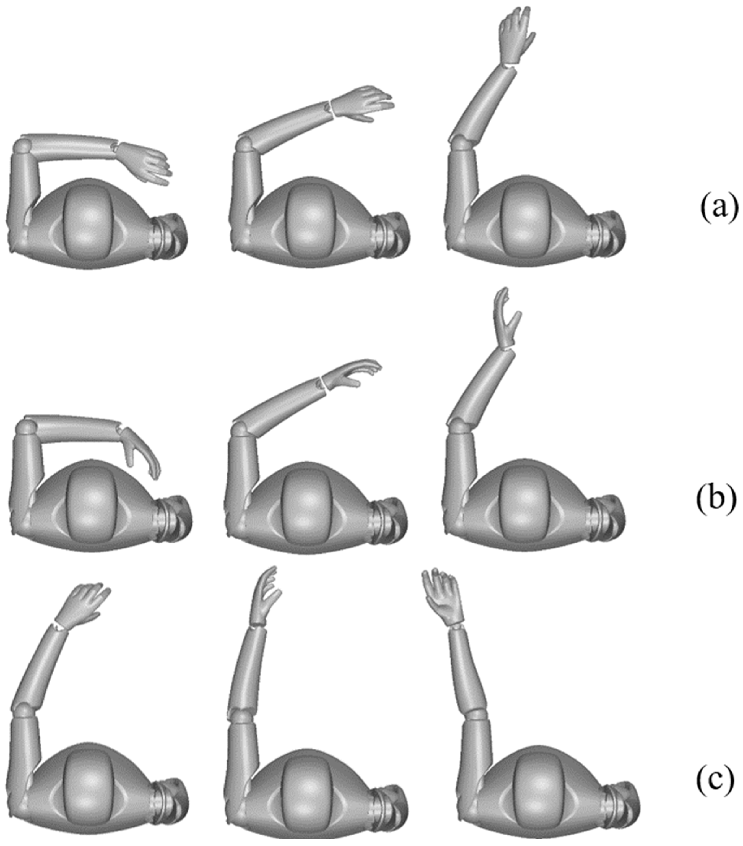
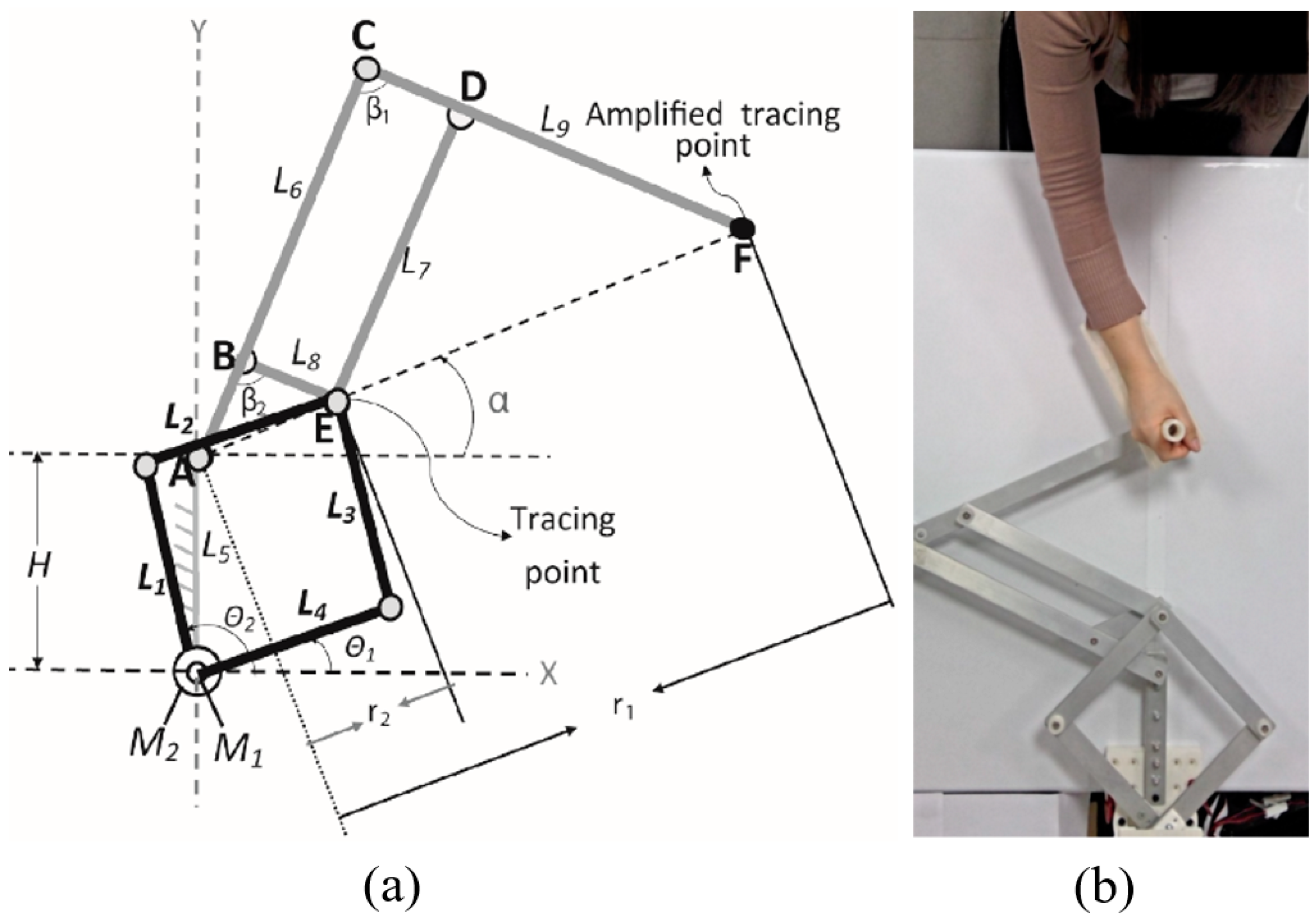
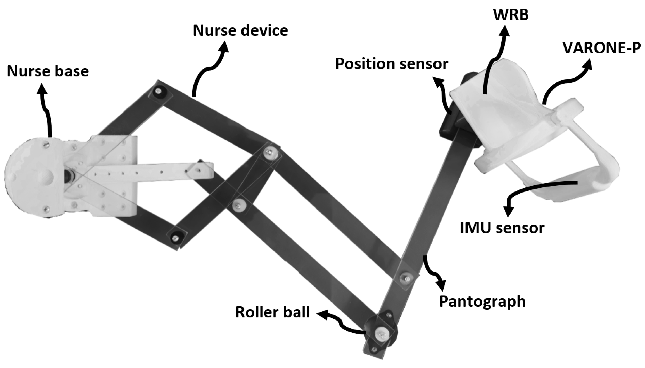
2.1. The NURSE Device

NURSE (cassiNo-qUeretaro uppeR limb aSsistive dEvice) is an upper limb planar movement passive assistance device. It can guide the motion of the human arm along predefined paths on a horizontal plane [23]. Its main features are summarized in Figure 4. The NURSE has two passive planar DoFs consisting of translations along the X and Y axes. The low number of DoFs significantly limits the exercises that can be performed. In particular, NURSE is not able to provide the required rotations that have been identified in the previous section. Hence, a specific novel device should be designed to cover this need. Accordingly, the VARONE device is proposed to work as a standalone or to complement the NURSE device and achieve a wide range of exercises with different wrist postures.

2.2. The Proposed Design Procedure for VARONE

In general, the design process starts with a high review of the state of the art, and then the requirement list is created. VARONE considers the adaptability to the NURSE device, sensing implementation, and wrist full-motion ADL. Moreover, the condition of design requirement verification is applied. Once the design requirements are met, the VARONE design is completed. The joint design configuration was identified by means of a topology search. It is inspired by the gimbal mechanical design [24] to obtain an ergonomic shape while enabling a full-range average human wrist motion. Note that VARONE is designed to incorporate energy storage devices. This strategic design allows for the potential realization of not only passive but also active operations in the future.

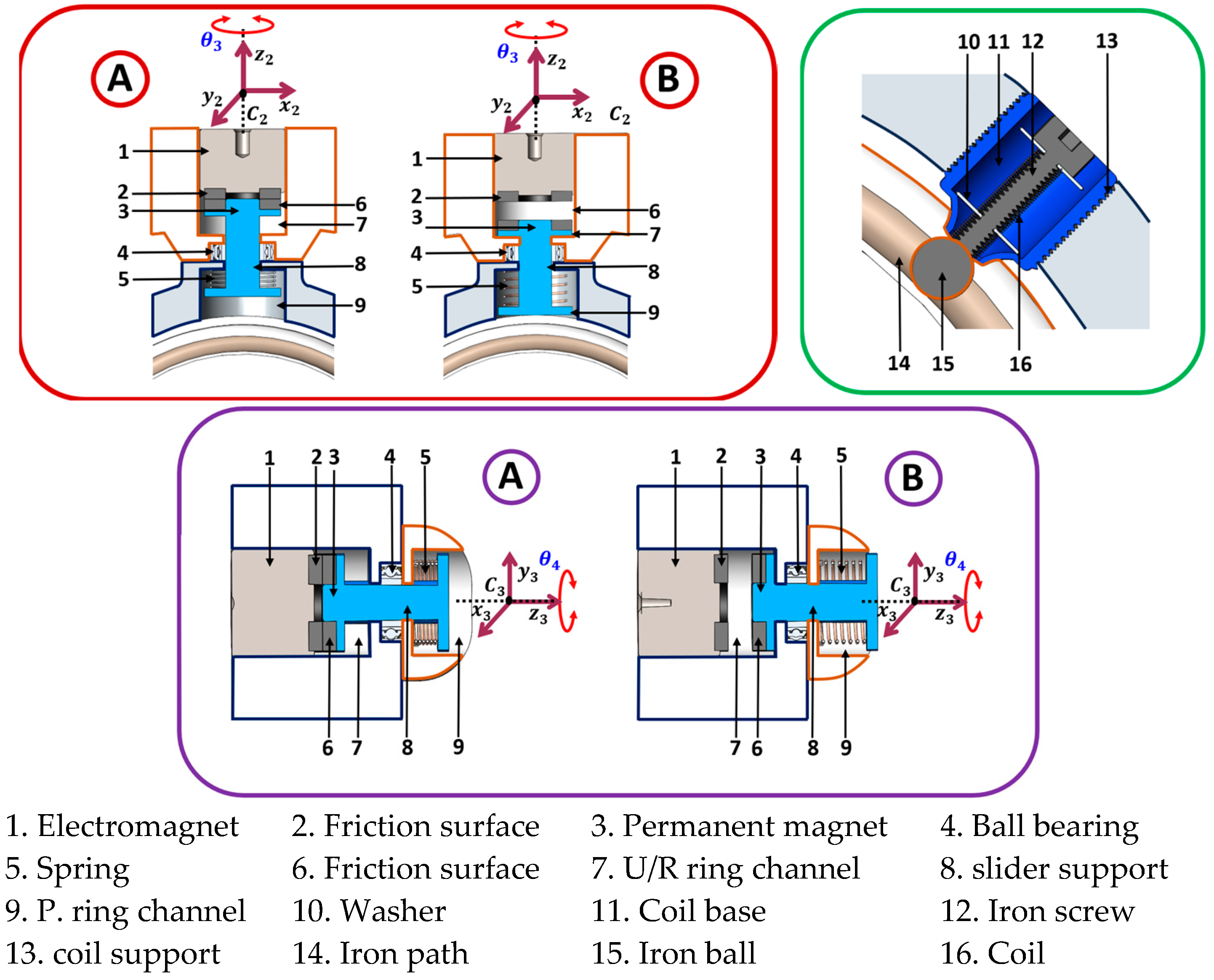
2.3. The Proposed Design Solution

The VARONE CAD model is shown in Figure 5. It is composed of the wrist support, pronosupination ring, ulnar/radial ring, and flexion/extension handgrip. The IMU sensor that measures and reports the angular rate is installed inside the handgrip. Each component is fixed to provide the 3-DoFs passive motion of the wrist joint. Each joint can provide variable resistance.
The VARONE device is composed of four bear points that connect the pronosupination ring link to the wrist support, allowing rotation around C 1 ; this movement is denoted as θ 2 . The ulnar/radial ring is positioned through a roller bearing, fixing it to the pronosupination ring, permitting the turn of the ulnar/radial ring throughout C 2 ; this rotation is called θ 3 . The flexion/extension handgrip is attached to the ulnar/radial ring using a roller bearing, creating motion all over C 3 ; this motion is named θ 4 . The friction effect of VARONE with the floor is through a spherical contact ball, as shown in Figure 5. It is worth noting that commonly variable stiffness joints are achieved using motors in combination with springs implementing Hooke’s law. We are proposing a novel approach based on using electromagnets as the attraction force and rubber as a contact material, as shown in Figure 6 and Figure 7. VARONE uses the friction principle to vary the resistance of radial/ulnar deviation and flexion/extension. The pronosupination movements implement the magnetic principle to create a resistance force, as depicted in Figure 8.
Models and simulations will be carried out in the following sections to prove the feasibility of the proposed design of VARONE. Note that VARONE can be used alone for human wrist assessments and exercising, or it can be used as the wrist of the NURSE device to create a 5-DoFs mechanism. The combined device is shown in the 3D model of Figure 9. The combination of VARONE with NURSE provides a wide range of feasible concurrent assessment and rehabilitation exercises.

3. Kinematic and F.E.M. (Finite Element Method) Analysis

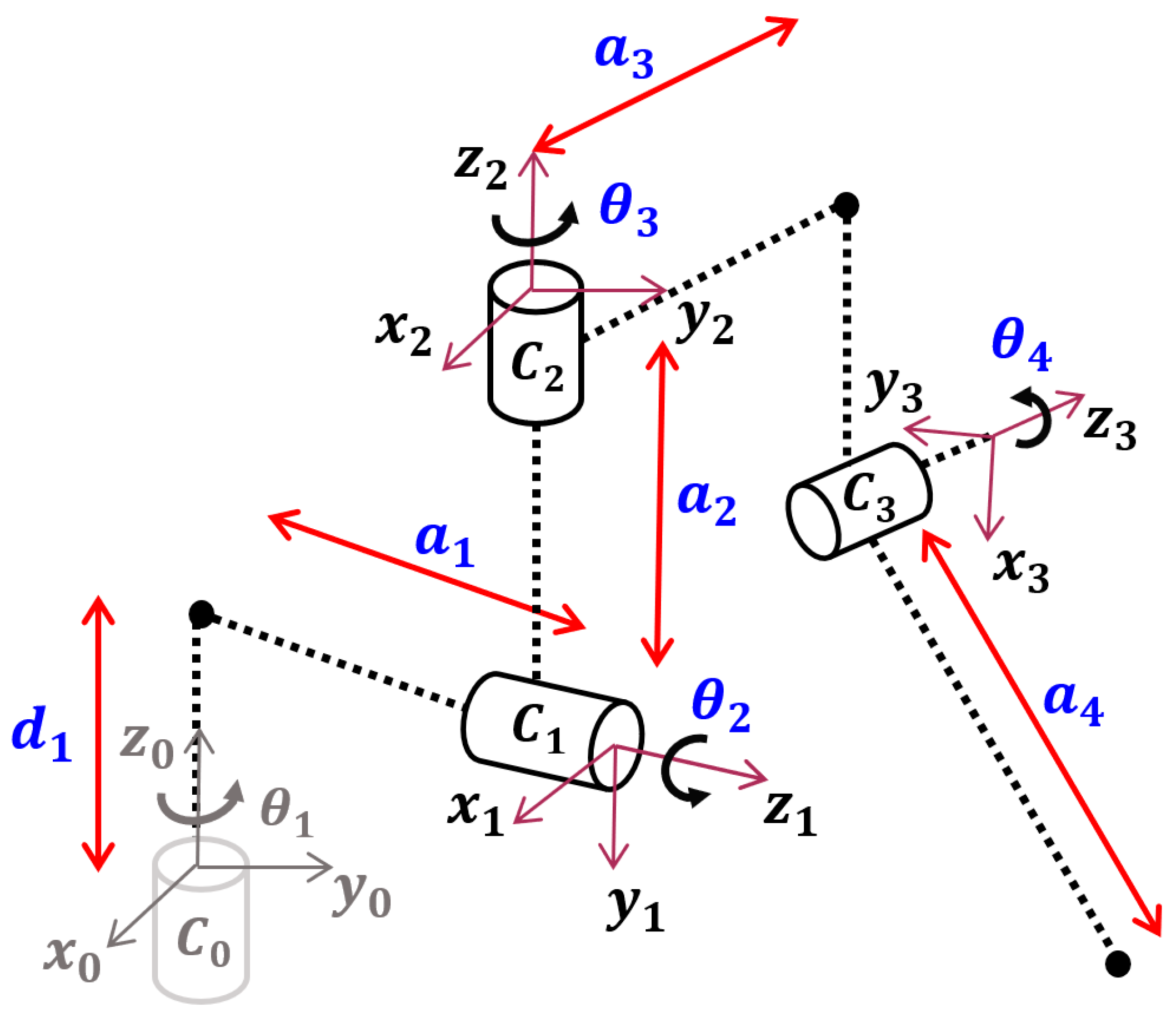
3.1. The Proposed Design Procedure for VARONE

The kinematic analysis of VARONE was created using the D–H parameters [25]. Figure 10 shows the kinematic study diagram. The coordinate system C 0 represents the initial reference moved through d 1 and a 1 to become C 1 with θ 2 value. This reference is shifted through a 2 to suit the position reference C 2 with the θ 3 variable. Finally, the location point is displaced through a 2 and a 3 to develop C 3 with θ 4 motion range and the a 4 maneuverability distance. For analysis purposes, θ 1 is the attached point between NURSE and VARONE. Therefore, θ 1 is a constant in the kinematic and dynamic analysis.
The relation between the variables and parameters shown in Figure 10 contrasted with the Denavit–Hartenberg parameters permits the creation of Table 2. The four joint displacement matrices are implemented into (1) to complete the motion matrix (2).
p 8   0 = i = 1 8 [ T i   i 1 ( q i ) ] p 8
T 4   0 = [ U x V x W x q x U y V y W y q y U z V z W z q z 0 0 0 1 ]
Equations (1) and (2) allow for the calculation of the end-effector position given the angular values of each DoF ( θ 1 , θ 2 , θ 3 , θ 4 ). However, in real applications, it is also necessary to solve the inverse kinematics problem.

3.2. Inverse Kinematic Analysis

The FE handgrip provides a space track motion (Figure 10) where the motion variables ( θ 2 , θ 3 , θ 4 ) must be computed using inverse kinematic analysis. Equation (2) is solved algebraically to determine the joint angles from a desired trajectory.
Computing T 4   1 (3) is solved as
T 4   1 = ( T 1   0 ) 1 T 5   0
Calculating θ 3 , it is required to use q z from (2), resulting in
θ 3 = sin 1 ( q y a 3 )
Calculating θ 2 , it is necessary to use W y and W z from (2), resulting in
W z 2 + W y 2 = sin θ 2 2 sin θ 3 2 + cos θ 3 2
sin θ 2 2 = W z 2 + W y 2 cos θ 3 2 sin θ 3 2
θ 2 = sin 1 ( W z 2 + W y 2 cos θ 3 2 sin θ 3 2 )
with θ 3 0 .
Calculating θ 4 , it is essential to use U x and U z from (2), which is obtained from (6).
U x = cos θ 2 cos θ 3 cos θ 4 sin θ 2 sin θ 4 U z = cos θ 3 cos θ 4 sin θ 2 + cos θ 2 sin θ 4
(6) is implemented using linear algebra, yielding
A   x = b A = [ cos θ 2 cos θ 3 sin θ 2 cos θ 3 sin θ 2 cos θ 2 ] , x = [ cos θ 4 sin θ 4 ] , b = [ U x U z ] a = sin θ 4 = ( U z cos ( θ 2 ) + U x sin ( θ 2 ) b = cos θ 4 = ( U x cos ( θ 2 ) U z sin ( θ 2 ) cos ( θ 3 )
θ 4 = tan 1 ( a b )  
It is possible to compute the velocity and acceleration values using the relationship between the configuration described in Figure 10 and (4), (5), and (7) after calculating the position values θ 2 , θ 3 , and θ 4 of the joint angles as follows:
T n   0 ˙ = [ R n V n ˙ 0 1 ] ˙ = i = 1 n [ θ i ˙ Z i 1 θ i ˙ Z i 1 P i 1 + d i Z i 1 0 1 ]
x ˙ = J   q ˙
x ˙ = [ i = 1 n [ θ i ˙ ( Z i 1 x P n   i 1 ) + Z i 1 d i ˙ ] i = 1 n [ θ i ˙ Z i 1 ] ] Z i 1 = R i 1   0 [ 0 0 1 ] T r i   i 1 = [ a i cos θ i a i sin θ i d i ] T P n   i 1 = R i 1   0 r i   i 1
J ( : , i ) = [ Z i 1   x P n     i 1   Z i 1 ]
where n = 1,…, 4 and x stands for cross product. The Jacobian formulation of the kinematic analysis is depicted in (9). Assuming that all the links are homogeneous and have a small cross-section, the position of the center of mass is given by P i 1 .
The model in (1)–(9) was implemented in Matlab, allowing for the calculation of the desired motions for performing rehabilitation exercises. Simulation results will be reported in the validation results section.

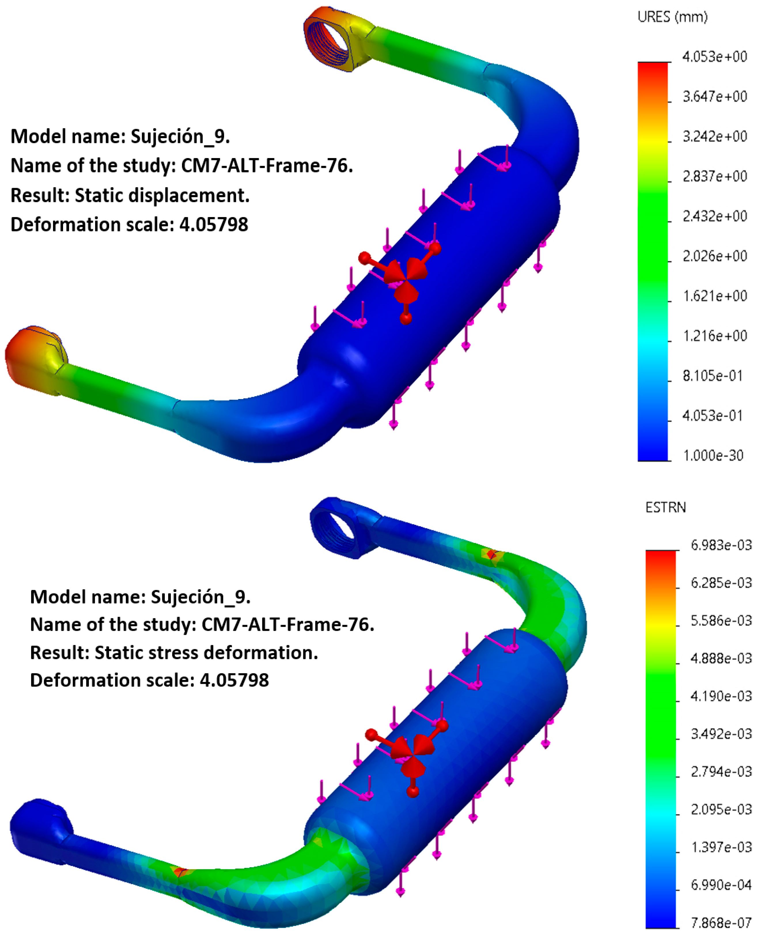
3.3. F.E.M. Analysis
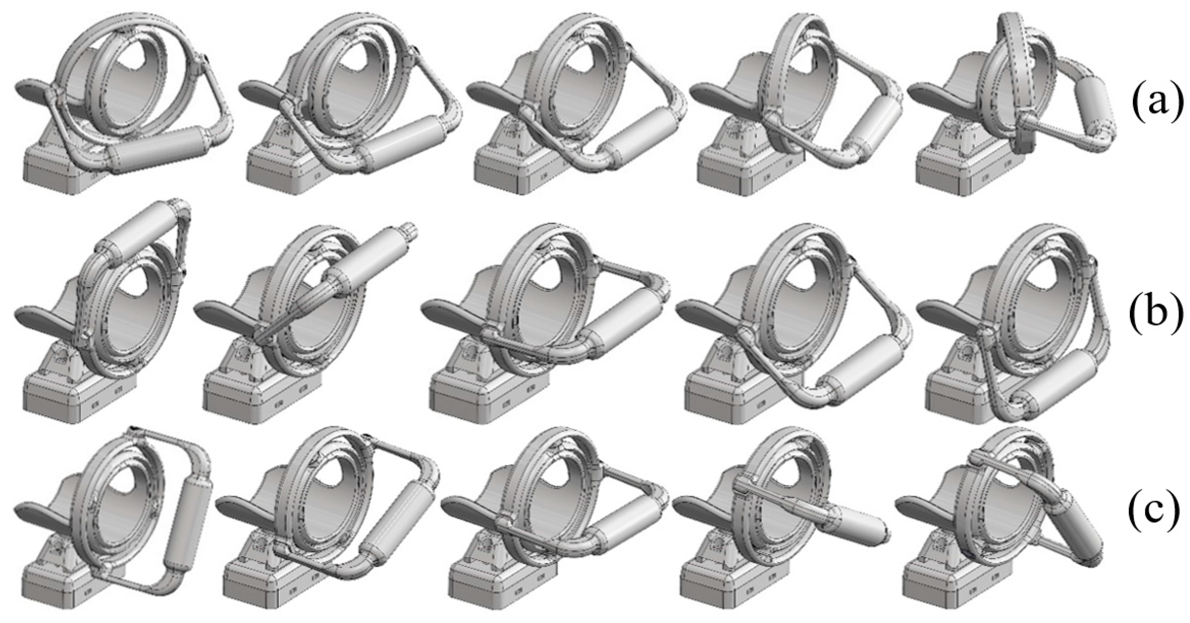
To demonstrate the feasibility of the VARONE, a linear static analysis was created using F.E.M. The static load used for the F.E.M. analysis is the hand and wrist weight in a constant force due to gravity; in this paper, we consider a 3.98 N vector downwards (0.406 kg hand weight) [26]. The base structure and the mechanical parts of the VARONE device are fabricated using PLA material. The general properties of PLA are listed in Table 3. The mechanical components in a general state of the 3D structure have been evaluated for the stress analysis criterion using the Von Mises stress function. Table 4 presents the mesh information for F.E.M.
Figure 11 shows the result of the FEM analysis of the FE handgrip; it presents the displacement analysis as well as the maximum value.

4. Dynamic Analysis

The VARONE prototype, shown in Figure 12, is fabricated with PLA (prototype weight, 0.858 kg) using the Creality K1 3D printer. Once the hand grips the FE handgrip while exerting force to produce a specific trajectory, the maneuver is constructed using combinate motion (x, y, θ 1 , θ 2 , θ 3 , θ 4 ). Thus, it is possible to develop the main wrist paths used in physiotherapy exercises (Figure 13).
The Lagrangian model and energy principles were used to generate dynamic analysis based on [23]. As shown in (10), the Lagrangian equation uses partial derivatives as a function of time, the velocity vector (8), and the position vector (4), (5), and (7).
One can write the Lagrange equation as
d dt ( L q i ˙ ) L q i = Q i ,   i = 1 ,   2 ,   ,   n
The inertial matrices are given by
I i = dp c dt v ρ dV = mv c
where I i denotes the inertial matrix and the dp c / dt represents the change in the position of the center of mass, ρ stands for the change in density, dV refers to the change in volume, m stands for mass, and v c depicts the linear velocity.
Examining Figure 10, the kinetic energy can be written as
K i = 1 2 V ci m i   T V ci + 1 2 w i I i   T w i
The velocity analysis used in (8) is written in matrix form using the theory of the instantaneous motion of the screw as
x ˙ ci = J i q ˙
where x ˙ ci = [ v ci w i ] , J i = [ J vi J wi ] .
Variable J i represents the Jacobian matrix of the linear and angular velocity, and x ˙ ci denotes the linear and angular velocity. Substituting (13) into (12) yields
K = 1 2 q ˙ T [ i = 1 n ( J vi m i   T J vi + J wi I i   T J wi ) ]
Defining the inertial matrix with the (n × n) dimension, the result can be reduced to
M = i = 1 n ( J vi m i   T J vi + J wi I i   T J wi )
The simplification allows for a smaller number of equations required to calculate the velocity coupling vector presented to complete the energy analysis. n = 1, 2,3)
V n = j = 1 3 k = 1 3 ( M n , j q vi 1 2 M j , k q n ) q ˙ j q ˙ k
The potential energy is represented by the gravitational vector; this energy is accumulated in the end-effector and is expressed by the amount of work required to raise the center of mass at each displacement in the therapy sessions. The gravitational vector (n = 1, 2, 3) is
G n = j = 1 3 m j g T P vi   n
The contribution of each gravitational vector is shown by the mass ( m j ) of the end-effector, the gravity vector ( g T ), and the position of the mechanism ( P vi   3 ).
To define the dynamic equation, we first replace (14) and (17) in (18) to obtain a condensed version of the Lagrangian shown in (19).
L = K U
L = 1 2 q ˙ T M q ˙ + j = 1 n m j g T P vi
The Lagrange function is used to calculate the contribution of kinetic and potential energy. Equation (20) provides the partial derivate relative to the position vector, while (21) provides the partial derivate of Lagrange with respect to the velocity vector.
L q i = 1 2 j = 1 n k = 1 n M j , k q i q ˙ j q ˙ k + j = 1 n m j g T J vj   i
d dt ( L q ˙ i ) = j = 1 n M i , j q ¨ j + j = 1 n k = 1 n M i , j q k q ˙ j q ˙ k
Using the compact version of the Lagrange function, (20) and (21) yield
M q ¨ + V + G = Q
V i = j = 1 n k = 1 n ( M i , j q k 1 2 M j , k q i ) q ˙ j q ˙ k ,   G i = j = 1 n m j g T J vj   i
The model in (10)–(22) was implemented in Matlab, allowing for the calculation of the required torques for performing rehabilitation exercises. Simulation results will be reported in the validation section (Section 5) to be compared with the experimental results.

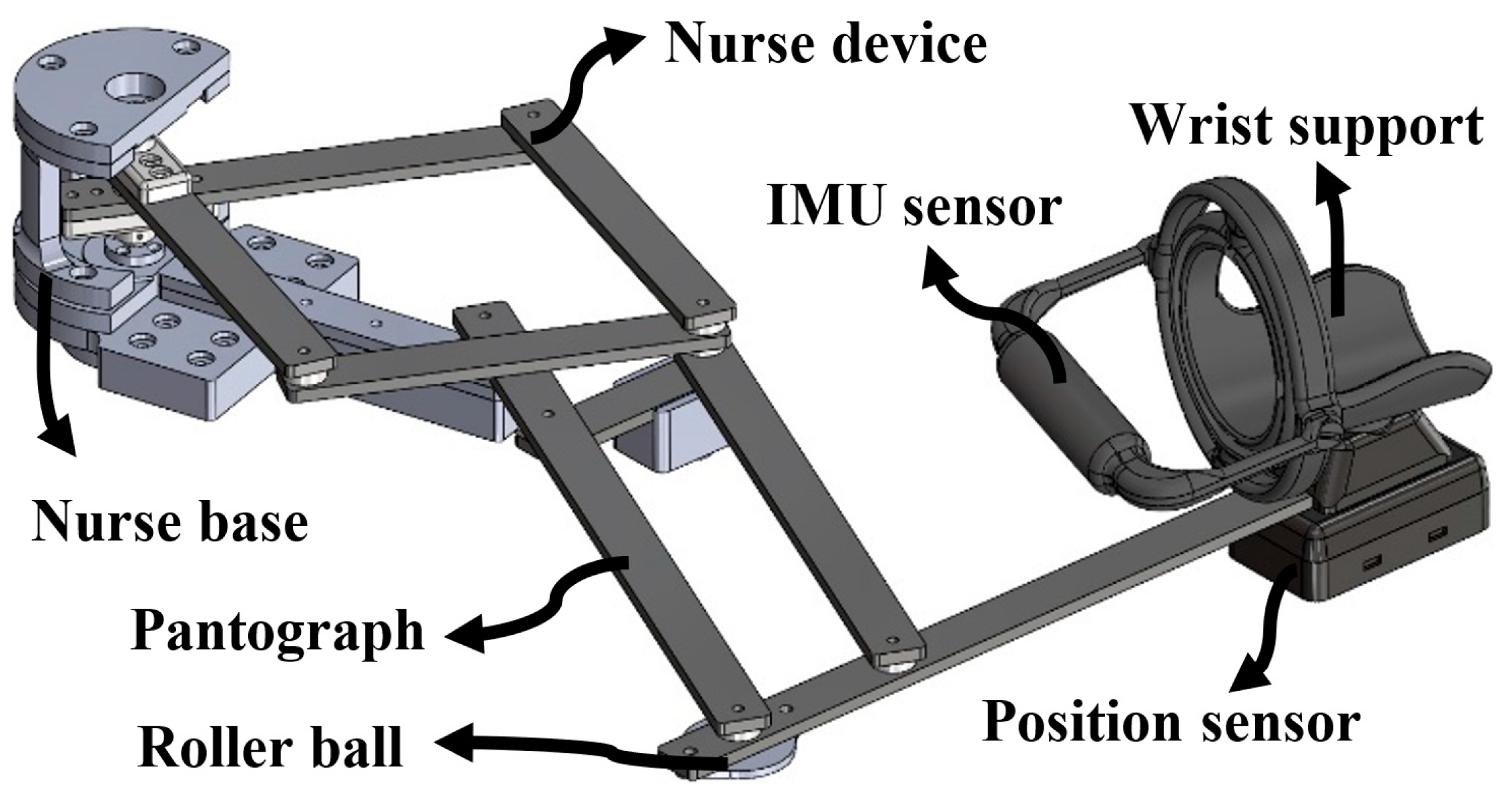
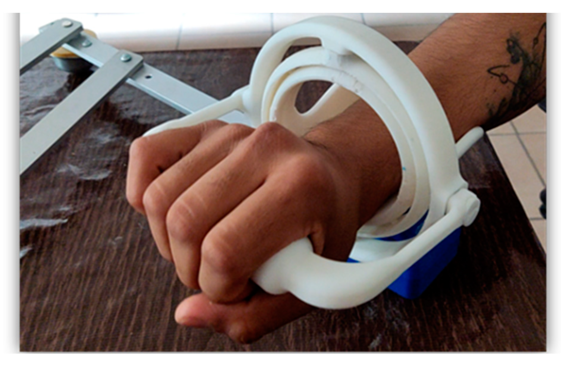
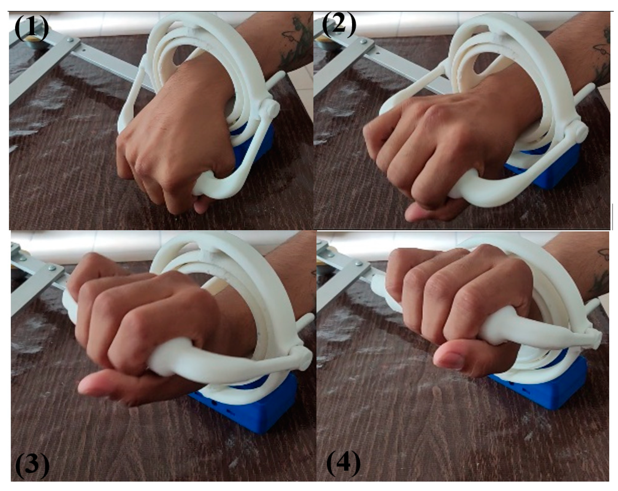
5. A Setup for Experimental Validation

The main advantage of this prototype is that it can be installed on a standard table and a chair for the user, as illustrated in Figure 14. It can be easily used at home, clinic, or laboratory.
The user then proceeds to generate the three-degree displacement for the wrist that a specialist has developed for him. Each shift and orientation created in the layout designed by the specialist is recorded by the hand grip sensors. Once the configuration is installed, each user must remain seated and grasp the handgrip while resting the forearm on the wrist support of the VARONE.

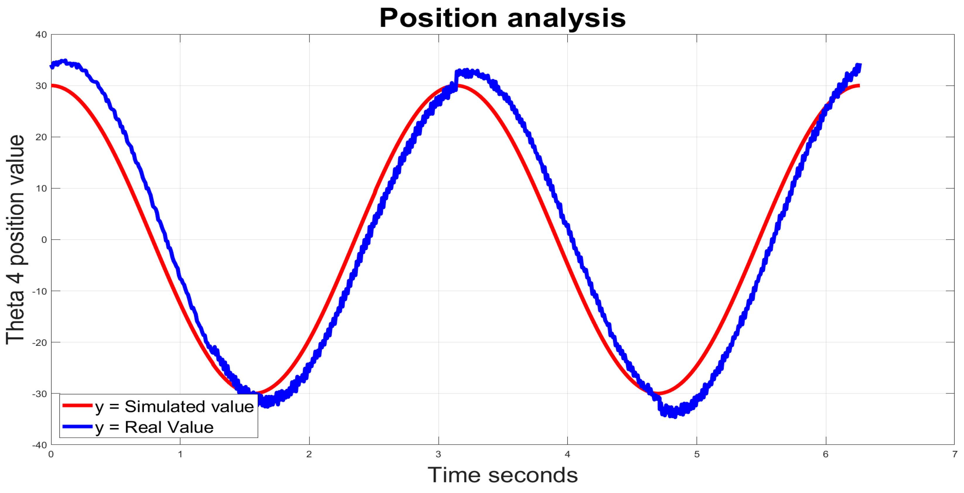
Validation Tests and Results

To determine the standard level of the kinematic device, the evaluation of θ 4 was carried out. Since the VARONE is portable and can be set up in any location, it was first attached to a clean table and connected to the NURSE device. Afterward, 30 healthy participants were invited as subjects (18 males and 12 females; age range: 22–42 years) to use the mechanism, and each participant must perform the same movement trajectory (23), considering the time employed. Once the position information was collected, the root mean square and a lower pass filter were applied. Finally, the collected data were sorted to provide an overview of the kinematical analysis.
p = 30   cos ( 2 f )
The handle, the component of the mechanism that interacts most with the upper limb, contains the sensing device, as shown in Figure 15. However, for research purposes, the electronic components are listed below:
  • Module MPU-9250;
  • Module CC2640R2F;
  • Lithium battery;
  • Microprocessor ARM ABX00032;
  • Imada ZTA-LM-110.
Note that informed consent has been required for each experimental test. The experimental method does not require ethical approval since VARONE is fully passive and there is no risk for a user. Once the user has completed the test, a satisfaction interview was employed to quantify the contentment level of each participant. For further details on the satisfaction interview, see [27].
The mechanism was prepared to transmit the position coordinates from the suggested trajectory calculated by (23), as shown in Figure 16. Once the electronics were installed into the FE handgrip, the subject was asked to perform the suggested trajectory. The results were compared with the solution of the kinematic equations once the data were collected using the microprocessor and transferred to the computer system through the CC2640R3F module, as shown in Figure 17.
The dynamic analysis results are presented, and the CAD model shown in Figure 5 highlights the joints’ coordinates. This analysis implies the use of an IMU and the IMADA sensor to quantify the necessary force to rotate the θ 4 joint. The results were recorded, processed, and represented as follows (23).
The desired motion (23) and the model constraints were trained using Solidworks movement analysis. Once the desired trajectory was analyzed, the physical and analytic results are depicted in Figure 18. This considers the external forces and the mass of the upper limb. The interaction torque was measured via Imada ZTA-LM-110 and IMU, which measure the perpendicular force required to rotate the joint θ 4 .
Contrasting the torque performance of the VARONE with the predicted trajectory demonstrates that the task maintains a sinusoidal function operation. However, the torque measurement gives different amplitudes and different frequency points due to external forces including hand, gravity variants, and the calibration of the force sensor.

6. Conclusions

In conclusion, this study addresses the existing gap in suitable devices for the quantitative assessment of various upper limb conditions requiring physical rehabilitation. The proposed solution, VARONE, emerges as a novel and portable device designed to simultaneously assess and rehabilitate the human wrist. When combined with the NURSE device, it forms a 5-DoFs mechanism, expanding the potential for concurrent assessment and rehabilitation of planar exercises across the entire upper limb. The paper provides a thorough analysis of the proposed design, covering its kinematic properties, static (FEM) modeling, and dynamic modeling. Special emphasis is given to our innovative design solution, utilizing electromagnets to achieve variable joint stiffness, allowing for the regulation of resistance in wrist motion and adjustment of stiffness in each degree of freedom, catering to patients with varying levels of injury. Following a comprehensive analysis of VARONE, we report the results of a preliminary experimental validation involving thirty users. This positions VARONE as a versatile, portable, and adaptable solution for the evaluation and treatment of upper limb movement disorders, as affirmed by the reported numerical models as well as by the experimental outcomes. In future work, VARONE will be able to record physiological signals from the patient; in this way, the combination of kinematical and physiological signals using artificial intelligence will bring a potential device to objectively measure the rehabilitation process in upper limb rehab sessions.

Author Contributions

Conceptualization, L.D.F.A. and G.C.; methodology, L.D.F.A.; validation, L.D.F.A., G.C. and M.A.L.; formal analysis, G.C., M.A.L. and E.C.C.; investigation, L.D.F.A. and E.C.C.; writing—original draft preparation, L.D.F.A.; writing—review and editing, L.D.F.A., G.C., M.A.L. and G.C.; visualization, L.D.F.A. and E.C.C.; supervision, E.C.C., G.C. and M.A.L.; funding acquisition, M.A.L. and G.C. All authors have read and agreed to the published version of the manuscript.

Funding

This paper was partially funded by the PNRR Next Generation EU “AGE-IT”—CUP H23C22000870006 and PNRR MUR project PE0000013-FAIR. The first author also acknowledges the partial support of CONACYT granting a scholarship for spending a research period at the University of Calabria.

Informed Consent Statement

Informed consent was obtained from all subjects involved in the study.

Data Availability Statement

Data are contained within the article.

Conflicts of Interest

The authors declare no conflicts of interest. The funders had no role in the design of the study; in the collection, analyses, or interpretation of data; in the writing of the manuscript; or in the decision to publish the results.

References

  1. World Stroke Organization (WSO). Global Stroke Fact Sheet 2022. Int. J. Stroke 2022, 17, 478. [Google Scholar] [CrossRef] [PubMed]
  2. Waller, E.; Bowens, A.; Washmuth, N. Prevalence of and prevention for work-related upper limb disorders among physical therapists: A systematic review. BMC Musculoskelet. Disord. 2022, 23, 453. [Google Scholar] [CrossRef] [PubMed]
  3. Noé, E.; Gómez, A.; Bernabeu, M.; Quemada, I.; Rodríguez, R.; Pérez, T.; López, C.; Laxe, S.; Colomer, C.; Ríos, M.; et al. Guía: Principios básicos de la neurorrehabilitación del paciente con daño cerebral adquirido. Recomendaciones de la Sociedad Española de Neurorrehabilitación. Neurología 2023, n. 244612681. [Google Scholar] [CrossRef]
  4. Pike, S.; Lannin, N.A.; Wales, K.; Cusick, A. A systematic review of the psychometric properties of the Action Research Arm Test in neurorehabilitation. Aust. Occup. Ther. J. 2018, 65, 449–471. [Google Scholar] [CrossRef] [PubMed]
  5. Brunnstrom, S. Motor testing procedures in hemiplegia: Based on sequential recovery stages. Phys. Ther. 1966, 46, 357–375. [Google Scholar] [CrossRef]
  6. Fugl-Meyer, A.R.; Jääskö, L.; Leyman, I.; Olsson, S.; Steglind, S. The post-stroke hemiplegic patient. 1. a method for evaluation of physical performance. Scand. J. Rehabil. Med. 1975, 7, 13–31. [Google Scholar] [CrossRef]
  7. Bohannon, R.; Smith, M. Upper extremity strength deficits in hemiplegic stroke patients: Relationship between admission and discharge assessment and time since onset. Arch. Phys. Med. Rehabil. 1987, 68, 155–157. [Google Scholar] [PubMed]
  8. Wang, C.; Peng, L.; Hou, Z.-G.; Li, J.; Zhang, T.; Zhao, J. Quantitative Assessment of Upper-Limb Motor Function for Post-Stroke Rehabilitation Based on Motor Synergy Analysis and Multi-Modality Fusion. IEEE Trans. Neural Syst. Rehabil. Eng. 2020, 28, 943–952. [Google Scholar] [CrossRef]
  9. Olesh, E.V.; Yakovenko, S.; Gritsenko, V. Automated Assessment of Upper Extremity Movement Impairment due to Stroke. PLoS ONE 2014, 9, e104487. [Google Scholar] [CrossRef]
  10. Sun, Y.; Zhang, D.; Liu, Y.; Lueth, T.C. FEM-Based Mechanics Modeling of Bio-Inspired Compliant Mechanisms for Medical Applications. IEEE Trans. Med. Robot. Bionics 2020, 2, 364–373. [Google Scholar] [CrossRef]
  11. Tschiersky, M.; Hekman, E.E.G.; Brouwer, D.M.; Herder, J.L. Gravity Balancing Flexure Springs for an Assistive Elbow Orthosis. IEEE Trans. Med. Robot. Bionics 2019, 1, 177–188. [Google Scholar] [CrossRef]
  12. Fan, H.; Wei, G.; Ren, L. Prosthetic and robotic wrists comparing with the intelligently evolved human wrist: A review. Robotica 2022, 40, 4169–4191. [Google Scholar] [CrossRef]
  13. Carbone, G.; Gherman, B.; Ulinici, I.; Vaida, C.; Pisla, D. Design issues for an inherently safe robotic rehabilitation device. Mech. Mach. Sci. 2018, 49, 1025–1032. [Google Scholar] [CrossRef]
  14. Kim, J.; Kim, J.; Jung, Y.; Lee, D.; Bae, J. A Passive Upper Limb Exoskeleton with Tilted and Offset Shoulder Joints for Assisting Overhead Tasks. IEEE/ASME Trans. Mechatron. 2022, 27, 4963–4973. [Google Scholar] [CrossRef]
  15. Demers, M.; Rowe, J.; Prochazka, A. Passive Devices for Upper Limb Training. In Neurorehabilitation Technology; Reinkensmeyer, D.J., Marchal-Crespo, L., Dietz, V., Eds.; Springer: Berlin/Heidelberg, Germany, 2022. [Google Scholar] [CrossRef]
  16. Chen, J.; Li, X. Determining human upper limb postures with a developed inverse kinematic method. Robotica 2022, 40, 4120–4142. [Google Scholar] [CrossRef]
  17. Ferreira, F.; De Paula Rúbio, G.; Dutra, R.; Van Petten, A.; Vimieiro, C. Development of portable robotic orthosis and biomechanical validation in people with limited upper limb function after stroke. Robotica 2022, 40, 4238–4256. [Google Scholar] [CrossRef]
  18. Iranzo, S.; Piedrabuena, A.; Iordanov, D.; Martinez-Iranzo, U.; Belda-Lois, J.M. Ergonomics assessment of passive upper limb exoskeletons in an automotive assembly plant. Appl. Ergon. 2020, 87, 103120. [Google Scholar] [CrossRef]
  19. Kikuchi, T.; Sato, C.; Yamabe, K.; Abe, I.; Ohno, T.; Kugimiya, S.; Inoue, A. Upper limb training/assessment program using passive force controllable rehabilitation system. In Proceedings of the 2017 International Conference on Rehabilitation Robotics (ICORR), London, UK, 17–20 July 2017; pp. 505–510. [Google Scholar] [CrossRef]
  20. Maura, R.M.; Rueda Parra, S.; Stevens, R.E.; Weeks, D.L.; Wolbrecht, E.T.; Perry, J.C. Literature review of stroke assessment for upper-extremity physical function via EEG, EMG, kinematic, and kinetic measurements and their reliability. J. NeuroEngineering Rehabil. 2023, 20, 21. [Google Scholar] [CrossRef] [PubMed]
  21. Bos, R.A.; Haarman, C.J.; Stortelder, T.; Nizamis, K.; Herder, J.L.; Stienen, A.H.; Plettenburg, D.H. A structured overview of trends and technologies used in dynamic hand orthoses. J. Neuroeng. Rehabil. 2016, 13, 62. [Google Scholar] [CrossRef]
  22. Miao, S.; Shen, C.; Feng, X.; Zhu, Q.; Shorfuzzaman, M.; Lv, Z. Upper limb rehabilitation system for stroke survivors based on multi-modal sensors and machine learning. IEEE Access 2021, 9, 30283–30291. [Google Scholar] [CrossRef]
  23. Chaparro-Rico, B.D.M.; Cafolla, D.; Ceccarelli, M.; Castillo-Castaneda, E. NURSE-2 DoF Device for Arm Motion Guidance: Kinematic, Dynamic, and FEM analysis. Appl. Sci. 2020, 10, 2139. [Google Scholar] [CrossRef]
  24. Sharma, S.; Dijkstra, T.; Prasad, R.V. Open Gimbal: A 3 Degrees of Freedom Open Source Sensing and Testing Platform for Nano- and Micro-UAVs. IEEE Sens. Lett. 2023, 7, 2502704. [Google Scholar] [CrossRef]
  25. Craig, J.J. Introduction to Robotics: Mechanics and Control, 3rd ed.; Pearson Prentice Hall: Upper Saddle River, NJ, USA, 2005. [Google Scholar]
  26. Yusuf, E.; Nelissen, R.G.; Ioan-Facsinay, A.; Stojanovic-Susulic, V.; DeGroot, J.; van Osch, G.; Middeldorp, S.; Huizinga, T.W.J.; Kloppenburg, M. Association between weight or body mass index and hand osteoarthritis: A systematic review. Ann. Rheum. Dis. 2010, 69, 761–765. [Google Scholar] [CrossRef] [PubMed]
  27. Satisfaction Interview. Available online: https://forms.gle/i6JMMCriyZth3iZw9 (accessed on 7 February 2024).
Figure 1. Human upper limb motion description (dashed lines stands for the bone axes, arrows represent the feasible motions).
Robotics 13 00029 g001
Figure 2. An example of motion tracking. (a) Record of the hand motion, (b) measured “∞” path trajectory.
Robotics 13 00029 g002
Figure 3. Wrist and arm exercises: (a) radial/ulnar deviation (max = 40°, min = −20°) with elbow flexion/extension (max = 90°, min = 0°), (b) wrist flexion/extension (max = 10°, min = −40°) with elbow flexion/extension (max = 90°, min = 0°), and (c) pronosupination (max = 90°, min = −60°) with elbow flexion/extension (max = 10, min = −10).
Robotics 13 00029 g003
Figure 4. NURSE. (a) Kinematical scheme, (b) a built prototype [23].
Robotics 13 00029 g004
Figure 5. 3D CAD model of VARONE.
Robotics 13 00029 g005
Figure 6. 3D CAD model of VARONE.
Robotics 13 00029 g006
Figure 7. Views of the cross sections A and B of VARONE’s 3D CAD model with list of main components.
Robotics 13 00029 g007
Figure 8. A scheme with the working principle of VARONE: showing two cases with electromagnet activation and without electromagnet activation.
Robotics 13 00029 g008
Figure 9. NURSE combined with VARONE mechanism.
Robotics 13 00029 g009
Figure 10. VARONE kinematic diagram.
Robotics 13 00029 g010
Figure 11. Displacement and stress deformation analysis for the handle of VARONE.
Robotics 13 00029 g011
Figure 12. A preliminary prototype of VARONE.
Robotics 13 00029 g012
Figure 13. Simulations of VARONE’s motion, (a) UR deviation, (b) wrist FE, (c) forearm pronosupination.
Robotics 13 00029 g013
Figure 14. Set up of experimental validation.
Robotics 13 00029 g014
Figure 15. FE handgrip position and orientation sensors (arrows identify the motion, forces and the sensor).
Robotics 13 00029 g015
Figure 16. Photo sequence taken from a video of a proposed trajectory for VARONE (1- initial configuration; 2- first intermediate configuration; 3-second intermediate configuration; 4-final configuration of a wrist motion).
Robotics 13 00029 g016
Figure 17. Results of the position analysis with comparison of numerical and experimental results.
Robotics 13 00029 g017
Figure 18. Dynamical equations results.
Robotics 13 00029 g018
Table 1. Upper-limb displacement ranges for ADL.
JointMovementRotation Ranges (Degrees)
GlenohumeralFlexion/extension330°–0°–90°
RadiohumeralFlexion/extension320°–0°–90°
Proximal/distalPronosupination270°–0°–60°
RadiocarpalFlexion/extension320°–0°–75°
Radial/ulnar310°–0°–20°
Table 2. D–H parameters of VARONE.
Joint i α i a i d i θ i
1 π / 2 a 1 d 1 θ 1
2 π / 2 a 2 0 θ 2
3 π / 2 a 3 a 3 θ 3
4 0 a 4 0 θ 4
Table 3. PLA general properties.
PropertiesValueUnits
Heat Deflection Temperature (HDT)126°F
Density1.24g/cm3
Tensible strength50MPa
Flexural strength80MPa
Impact strength96.1J/m
Shrink rate0.37–0.41%in/in
Heat deflection temperature (HDT)126°F
Density1.24g/cm3
Table 4. PLA mesh properties.
Mesh TypeSolid Mesh
Mesher usedCurvature-based mesh
Jacobian points3
Maximum element size68.34 mm
Minimum element size4.54 mm
Total nodes254,567
Total elements257,980
Disclaimer/Publisher’s Note: The statements, opinions and data contained in all publications are solely those of the individual author(s) and contributor(s) and not of MDPI and/or the editor(s). MDPI and/or the editor(s) disclaim responsibility for any injury to people or property resulting from any ideas, methods, instructions or products referred to in the content.

