Article

Design of a Wheelchair-Mounted Robotic Arm for Feeding Assistance of Upper-Limb Impaired Patients

1
DIMEG, Department of Mechanics, Energy, and Management Engineering, University of Calabria, 87036 Rende, Italy
2
CESTER, Research Center for Industrial Robots Simulation and Testing, Technical University of Cluj-Napoca, 400641 Cluj-Napoca, Romania
3
Technical Sciences Academy of Romania, 010413 Bucharest, Romania
*
Author to whom correspondence should be addressed.
Robotics 2024, 13(3), 38; https://doi.org/10.3390/robotics13030038
Submission received: 13 January 2024 / Revised: 13 February 2024 / Accepted: 20 February 2024 / Published: 26 February 2024

Abstract

:
This paper delineates the design and realization of a Wheelchair-Mounted Robotic Arm (WMRA), envisioned as an autonomous assistance apparatus for individuals encountering motor difficulties and/or upper limb paralysis. The proposed design solution is based on employing a 3D printing process coupled with optimization design techniques to achieve a cost-oriented and user-friendly solution. The proposed design is based on utilizing commercial Arduino control hardware. The proposed device has been named Pick&Eat. The proposed device embodies reliability, functionality, and cost-effectiveness, and features a modular structure housing a 4-degrees-of-freedom robotic arm with a fixing frame that can be attached to commercial wheelchairs. The arm is integrated with an interchangeable end-effector facilitating the use of various tools such as spoons or forks tailored to different food types. Electrical and sensor components were meticulously designed, incorporating sensors to ensure user safety throughout operations. Smooth and secure operations are achieved through a sequential procedure that is depicted in a specific flowchart. Experimental tests have been carried out to demonstrate the engineering feasibility and effectiveness of the proposed design solution as an innovative assistive solution for individuals grappling with upper limb impairment. Its capacity to aid patients during the eating process holds promise for enhancing their quality of life, particularly among the elderly and those with disabilities.

1. Introduction

Over the years, the integration of robotic systems into the field of rehabilitation has become increasingly prevalent. This advancement has facilitated the adoption of new technologies aimed at enhancing functional recovery in human physiology, and in cases of trauma or highly invasive pathologies, it aims to provide users with a degree of independence and a semblance of normalcy [1]. According to a report conducted by the World Health Organization in the last decade, approximately 15% of the global population lives with some form of disability [2]. Additionally, between 2.2% and 3.8% of individuals experience functional limitations, a statistic that is on the rise due to aging populations and chronic conditions [3]. These statistics have led to the emergence of a new market and, consequently, the rapid development of robotic devices tailored for rehabilitation or assistance. Irrespective of their intended application, these robotic systems can generally be categorized into three types: conventional systems, robotic/exoskeletal systems, and robotic arms for wheelchairs [4]. The latter category combines a workstation with a mobile-based robot, aiming to provide independence and simple assistance to the elderly and disabled, thereby addressing the complex tasks of daily life [5,6].
Over the past two decades, various manipulators have been introduced to the market, customising their features to meet the needs of end users, and demonstrating their benefit in performing the required tasks [1]. Several examples of such devices are currently available on the market. Manus, developed by Exact Dynamics, is a 6-degrees-of-freedom (DoFs) robot equipped with a gripper as an end-effector. It is mounted on the left side of the operator and controlled using a joystick and a 16-button keyboard [7]. The Manus project led to the creation of the final iARM model [8], also a 6-DoF robot weighing 9 kg. It is powered by the same battery as the wheelchair, boasts a reach of 90 cm, and has a lifting capacity of 1.5 kg. Control options include keyboard, joystick, or a single button.
Another device, Raptor, introduced by Phybotics in 2008 [6], is a Wheelchair-Mounted Robotic Arm (WMRA) featuring a 4-DoF manipulator with two gripping fingers made of polymer material. It is mounted on the right side of the wheelchair and can be controlled via joystick/keyboard or using Sip and Puff (SNP) technology [9]. The University of Pittsburgh has conducted numerous studies showcasing Raptor’s effectiveness in various daily activities [10]. Jaco, marketed since 2009 by the Canadian company Kinova [11], is a 6-DoF manipulator designed for patients with upper limb disabilities such as muscular dystrophy or spinal injuries. Weighing just 5 kg, it offers easy usability and robust gripping capabilities thanks to its three-fingered end-effector, along with software programmability [12]. However, like most devices currently on the market, Jaco is expensive and requires a certain level of understanding and visual skills to be fully utilized.
In addition to industrial products, numerous global research groups have developed a variety of prototypes for Wheelchair-Mounted Robotic Arms (WMRAs) and explored innovative approaches in the realm of robotic solutions for meal assistance. For instance, the Korea Advanced Institute of Science and Technology (KAIST) has designed two 6-degrees-of-freedom (DoFs) manipulators, KARES I [13] and KARES II [10]. KARES I can be controlled manually via a keyboard or voice commands, while KARES II can be guided by a vision system, sensory glove, or electromyographic (EMG) signals, empowering users to autonomously execute a range of actions. The Automation Institute at the University of Bremen developed FRIEND II in 2007 [14], a 7-DoF manipulator equipped with a brain–computer interface capable of interpreting signals through electroencephalography. This interface enables users to perform actions without relying on limb movement. The Bath Institute of Medical Engineering has introduced Weston [15], an assistive robot utilizing a SCARA robot with five motors on its upper arm. Though slightly larger than other WMRAs, Weston offers a more expansive workspace, allowing it to comfortably approach tables and desks from its rear-mounted position. Asimov, a WMRA designed by the University of Lund, Sweden [16], features a modular structure with 8-DoF. Controlled via a joystick, each module is driven by independent motors, enhancing flexibility and adaptability. Furthermore, Perera et al. [17] presented an EEG-controlled meal assistance robot with camera-based automatic mouth position tracking and mouth open detection. Building upon this, Candeias and colleagues [18] introduced vision-augmented robot feeding. Park et al. [19] shared insights on active robot-assisted feeding using a general-purpose mobile manipulator, offering valuable perspectives on design, evaluation, and lessons learned. Additionally, Song et al. [20] conducted a usability test on the KNRC self-feeding robot, shedding light on its performance. Bilyea and colleagues [21] provided a comprehensive overview of robotic assistants in personal care through a scoping review, contributing valuable insights for future developments in the field.
In summary, assistive robotics technology has demonstrated its effectiveness in enhancing autonomy and aiding elderly and disabled individuals [22]. Studies have reported a 40% increase in daily activities and a 30% reduction in caregiver demands [23,24]. When comparing commercially available devices with those under development and various innovative approaches in robotic meal assistance solutions, it becomes evident that commercial manipulators offer established solutions characterized by high costs. On the other hand, prototypes and research solutions represent the technological forefront with innovative and advanced approaches, albeit requiring further development and potentially being less affordable. This situation is influenced by factors such as continuous maintenance, significant size, and notably high costs. The cost issue is exacerbated by the lack of financial recognition from insurance plans and subsidies [25], with costs increasing in correlation with payload capacity and degrees of freedom, as also mentioned in [26].
Considering the current absence of a cost-effective, user-friendly, and easily portable solution, this study introduces the mechanical, electrical, and control design of the “Pick&Eat” device as shown in Figure 1. This device is a wheelchair-mounted robotic arm designed to provide autonomous assistance to patients with upper limb paralysis during mealtimes. The proposed design has been meticulously engineered to prioritize flexibility, adaptability, efficiency, and ease of use. The device is designed to seamlessly adapt to wheelchairs of various sizes without causing disturbance or impedance. Additionally, the inclusion of an interchangeable end-effector allows users to select between a fork and a spoon based on individual preferences and needs. The primary objective of this work is to propose an innovative, reliable, cost-effective, and user-friendly device that enhances the quality of life for individuals by promoting functional independence while minimizing assistance costs.
This manuscript is structured as follows: Section 2 details the mechanical design of the proposed Pick&Eat device, with particular emphasis on the preliminary analyses conducted and the modelling. Section 3 focuses on the kinematic analyses performed to characterise the device under consideration, in order to ensure proper operation and identify the different permissible configurations. Section 4 highlights the dynamic analyses conducted, which are necessary to accurately size the hardware components and achieve the performance required to meet the desired target requirements. Section 5 analyses the entire control architecture, providing details on the electronic configuration and highlighting the sensor components employed to ensure adequate and stable device operation. Section 6 reports the experimental results obtained, demonstrating both the feasibility and effectiveness of the proposed design, the use of which claims significant independence for users with upper limb paralysis. A preliminary version of this paper has been presented at the IFToMM World Congress 2023 held in Tokyo, Japan, [27].

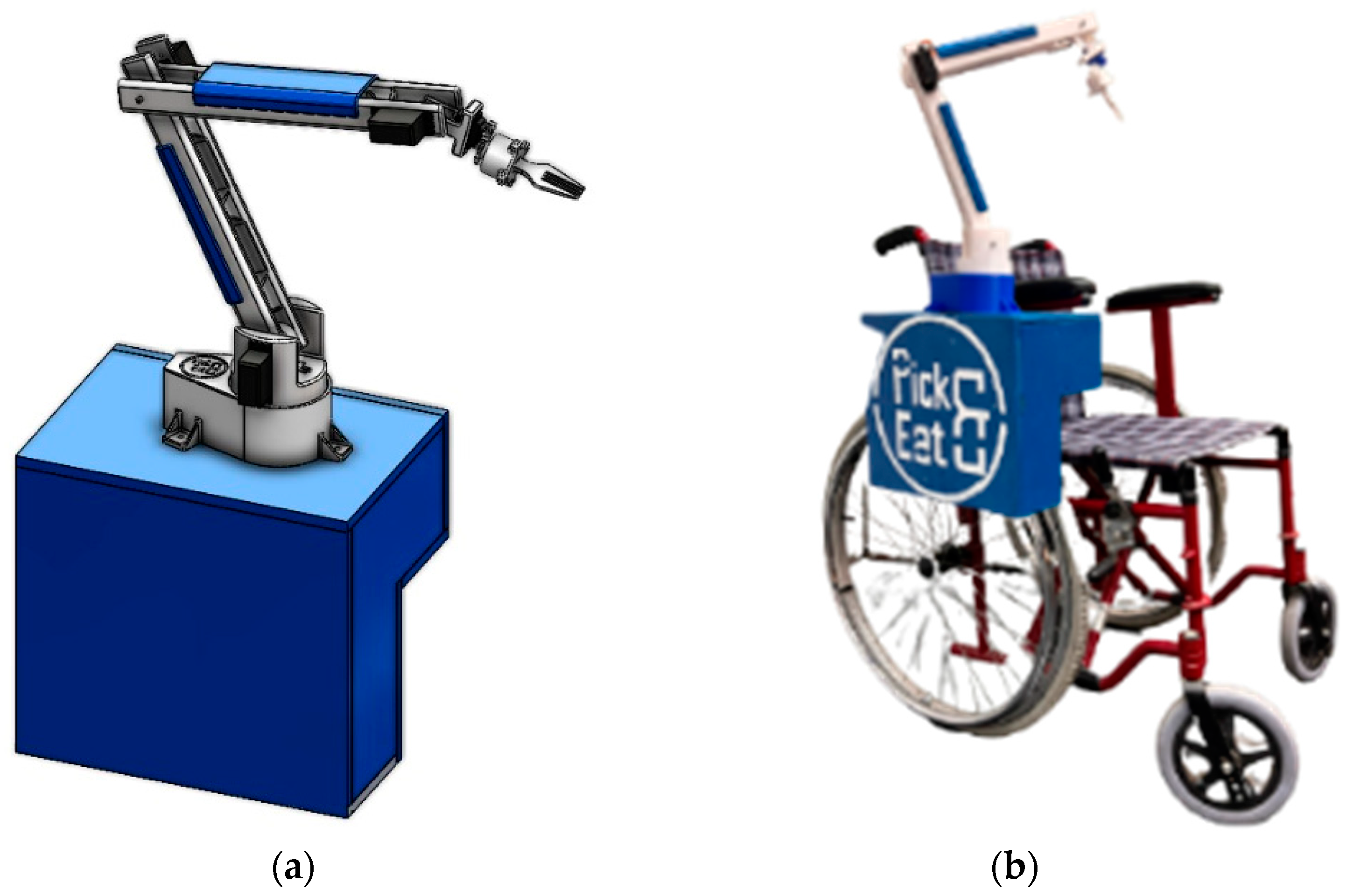
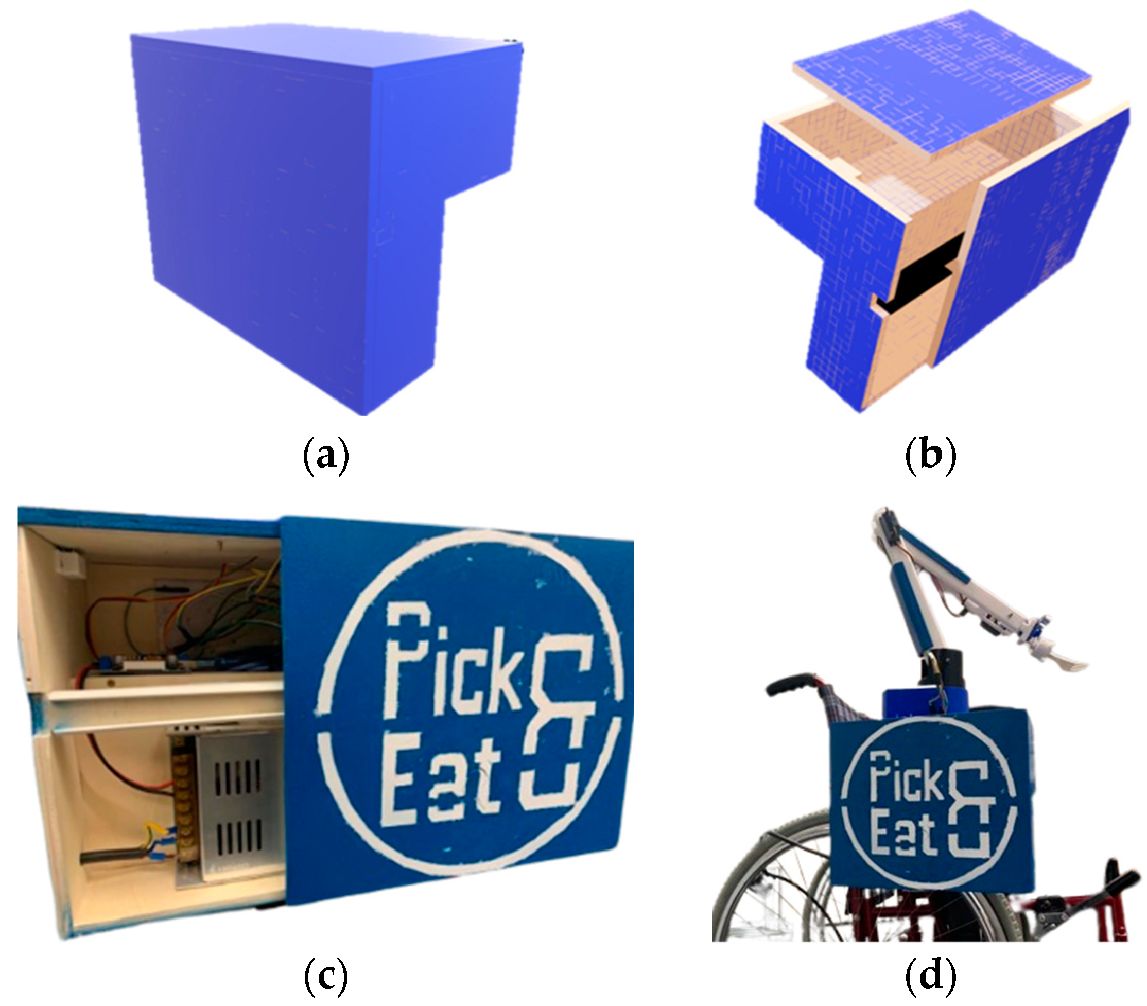
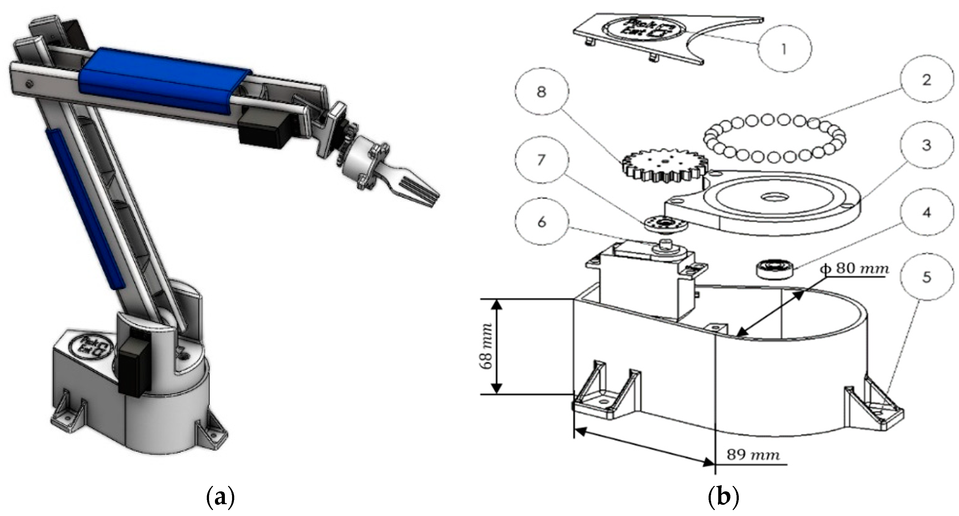
2. Mechanical Design

One should note that the proper functioning of the device in terms of human-like food feeding motions requires three independent translations and one rotation. Accordingly, the goal of the developed 4-DoF system is to provide a practical and reliable support for users’ feeding.
Following a thorough analysis of the literature and currently available technologies on the market [6,7,8,9,10,11,12,13,14,15,16,17,18,19,20,21,22,23,24,25,26], it was possible to identify the technical and performance specifications required for the product, outlining the following design requirements:
  • Adaptability to different types of wheelchairs.
  • Device length less than 70 mm (to meet the workspace and necessary manoeuvres without being cumbersome).
  • Allow a payload of up to 0.1 Kg (necessary to ensure the lifting of food).
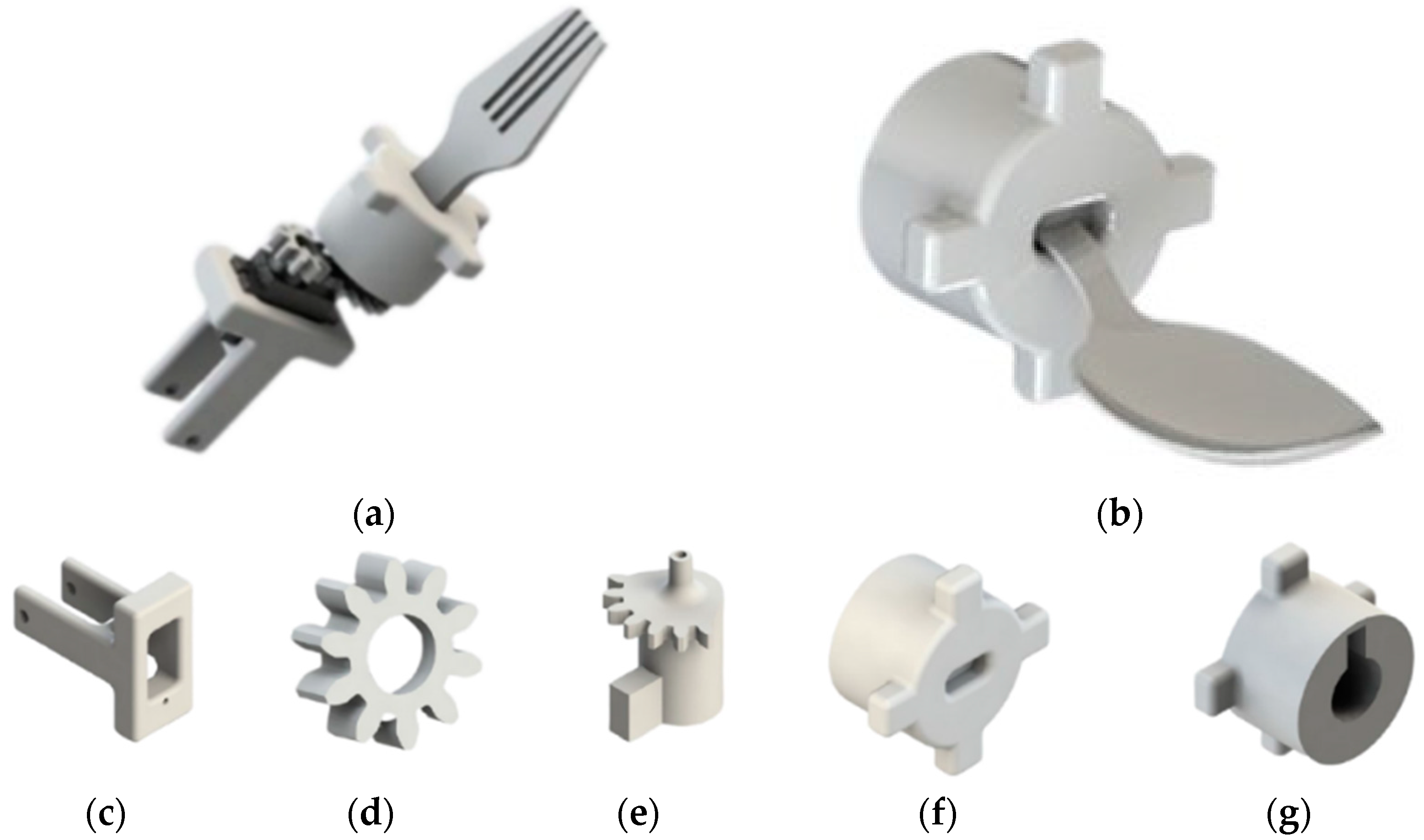
  • Interchangeability of the end-effector (ability to use a spoon or fork depending on the dish on the plate).
  • DC power supply ranging from 12 to 24 V.
  • Manipulator weight less than 1 kg (for portability and to avoid instability).
  • Ensure a high level of safety through appropriate sensors (to avoid possible impacts and/or collisions).
  • Speed less than 3 cm/s (for proper and timely task execution).
As additional requirements, the device must be easy to install, user-friendly, feature eco-friendly materials, and not require specific professional skills for fully autonomous operation.

2.1. Preliminary Analysis

Before proceeding to the modelling of the prototype and the subsequent motion analysis, it was essential to conduct a study of the movements required to complete the task. To achieve this goal, a team member was filmed while eating and, using the ‘motion tracking’ function of the commercial software DaVinci Resolve Studio version 18 (Figure 2a), it was possible to identify the essential movements, identify the degrees of freedom (DoFs) and determine the usable workspace. The results of this analysis showed the need to perform four basic movements, defined in order of execution as ‘Home Phase’, ‘Tool Phase’, ‘Pick Phase’ and ‘Users Eat Phase’, whose behaviour is described in the logic state diagram in Figure 2b. Consequently, it was decided to characterise the device with only four degrees of freedom (DoFs) and a working space of 450 × 350 × 400 mm3, as illustrated in Figure 3.

2.2. Design Overview

In compliance with the design requirements and based on the preliminary analyses conducted, we adopted several creative tactical strategies in the design process. The use of morphological graphs facilitated the synthesis of the topology of our device, shown in Figure 1, by characterising it into three main modules: the frame, the central body, and the end-effector. The components of these modules were created by CAD modelling and then manufactured by 3D printing, ensuring a lightweight and functional design.
The frame, visible in Figure 4a, with dimensions 260 × 300 × 195 mm3, is characterised by an L-shaped geometry specially designed to allow connection to several wheelchairs without interfering with the movement of the wheel. To facilitate future maintenance, there are two removable panels: the upper one secured with magnetic clips while the front one equipped with a linear guide for easy movement (Figure 4b). It also provides space to accommodate the necessary electronic components (Figure 4c), ensuring a robust design made entirely of wood with a total weight of 2.33 kg. The frame is designed to be installed and secured on both sides of the wheelchair, according to the individual needs of each patient. The central body of the device is then mounted onto it, as clearly depicted in Figure 4d.
The central body (Figure 5a) is a 4-DoF manipulator with three links, one of which is the end-effector. It consists of a base and a housing module attached to the frame, on which two links are mounted. The exploded view of the base, which can be seen in Figure 5b, allows the housing module to rotate by means of gear and bearings, ensuring the necessary movement by means of a servomotor (MG996R Digital Servo—Stall Torque: 9.4 kgf cm (kg force centimetres), 4.8 V, 500 mA, 0.17 s/60°). Both manipulator arms, measuring 295 × 447 × 30 mm3, have been designed to ensure the movement necessary to bring the food from the plate to the user’s mouth, while also considering the aesthetics and size of the respective servomotors (respectively: a HITEC D485 HW—Stall Torque: 4.8 kgf cm, 4.8 V, 500 mA, 0.2 s/60° and a MG996R Digital Servo—Stall Torque: 9.4 kgf cm, 4.8 V, 500 mA, 0.17 s/60°).
The dimensions are the result of a thorough analysis of the required movement and the topology of the structure. They are characterised by through slots that reduce weight and allow for the passage of motors and wiring; the result of the analyses carried out later is in Section 2.3. In addition, there is a specially designed cover to increase the safety of the device.
Finally, the end-effector (Figure 6a) represents the main element of our device, specifically designed to facilitate the user during the eat action. Its distinctive feature lies in interchangeability, offering to the users the possibility to use a fork (Figure 6a) or a spoon (Figure 6b) according to their personal preferences. This component can be divided into two fundamental parts: the actuation mechanism, designed to ensure a smooth transition between utensils, and the interchangeable module. The actuating mechanism consists of a base firmly anchored to the second link of the manipulator (Figure 6c), which houses the micro servo motor (SG90 Microservomotor—Stall Torque: 2.5 kgf cm (kgforce centimeter) 4.8 V, 500 mA, 0.1 s/60°). Attached to it is a gear wheel (Figure 6d) which engages with a cylindrical pin in the form of a mechanical tongue (Figure 6e).
The interchangeable module, depicted in Figure 6f, features a cross-shaped upper part with a hole, specifically designed to insert the fork or spoon, facilitating the switch between utensils. In the lower part of this module (Figure 6g), there is a hole intended to house the cylindrical pin, thus allowing for easy interchangeability of utensils.
The rotation and exchange process begin when the user wishes to change the utensil. The micro servo motor rotates the gearwheel. The gearwheel rotates acylindrical pin with the tab that was designed to allow a 120° rotation with the interchangeable module shape. This movement enables the quick detachment of the in-use utensil, providing a fast utensil change. The assembly of the different parts results in an overall length of the end-effector of 86 mm, not including the fork or spoon (in which case it is approximately 150 mm).

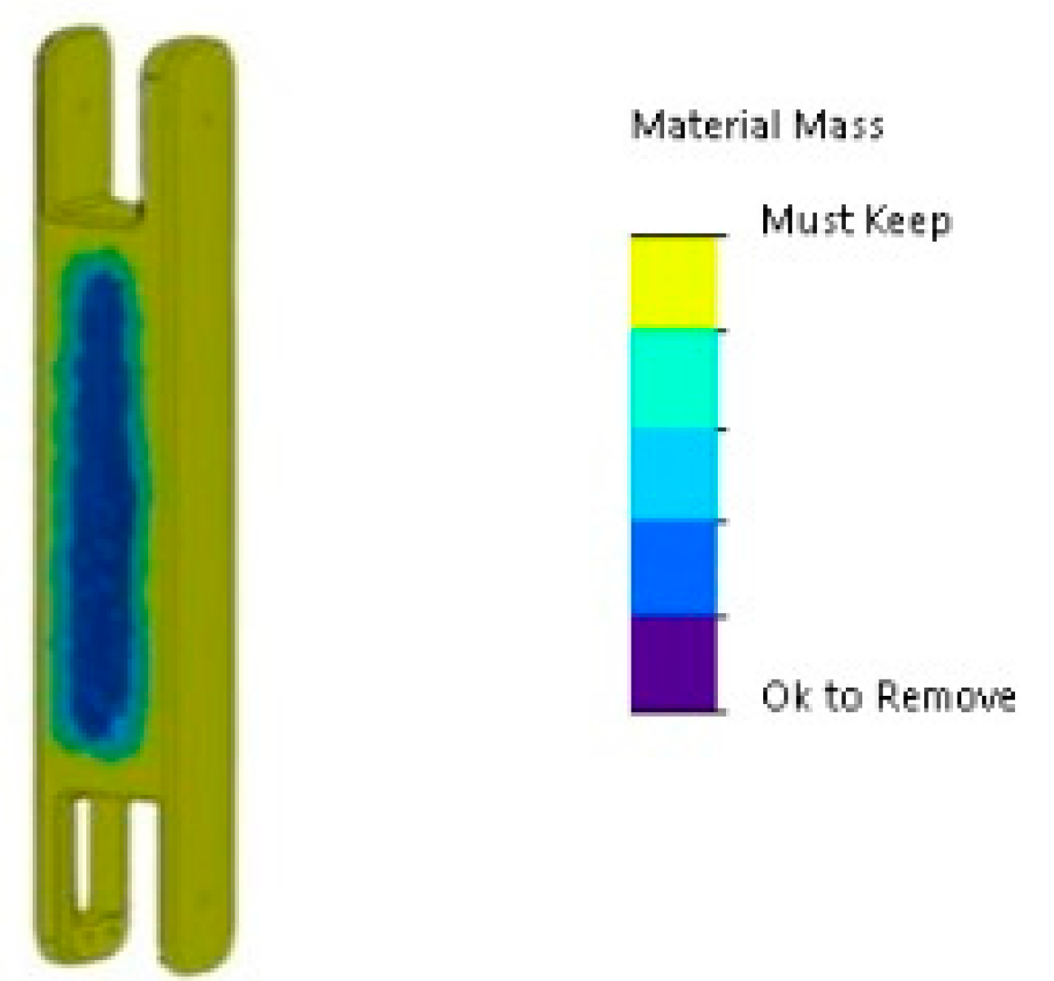
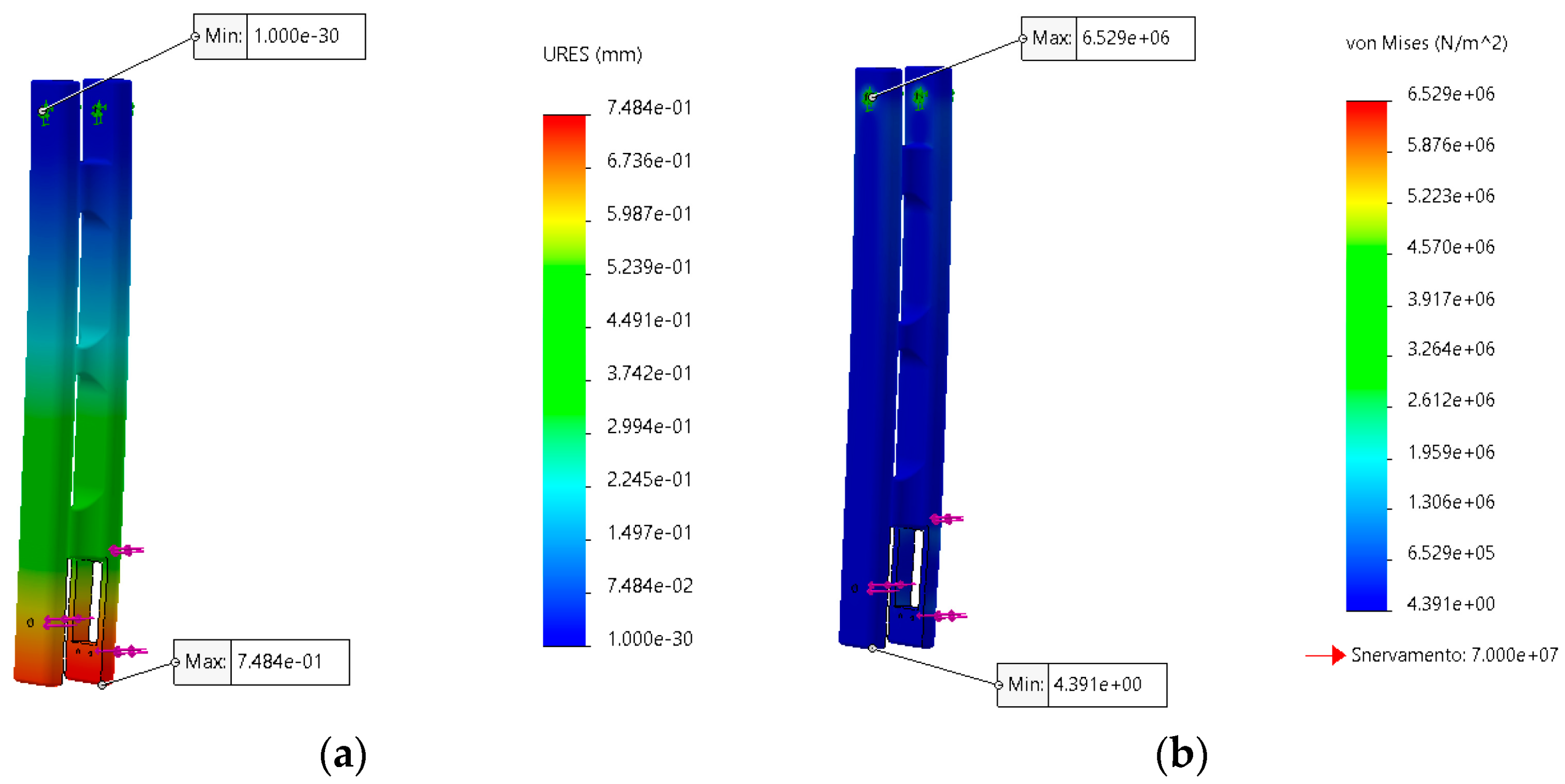
2.3. FEM Simulations

Several simulations were conducted with SolidWorks to optimise the design and ensure the strength of the two links under high stress. The initial design was analysed statically, revealing excessive weight and displacement around the motor housing. Therefore, a topological analysis (Figure 7) was conducted on the first design, which revealed that material could be removed from the front faces of the two links. This allowed the design of the two links to be optimised, resulting in a weight reduction percentage of approximately 32%.
Once the optimal design was identified, further analyses were carried out. In particular, the load was gradually increased from 5 N to 10 N per side to account for the cross-sectional difference obtained from the rapid prototyping and software calculations. The results of the Von Mises stresses and the maximum displacement are shown in Figure 8.

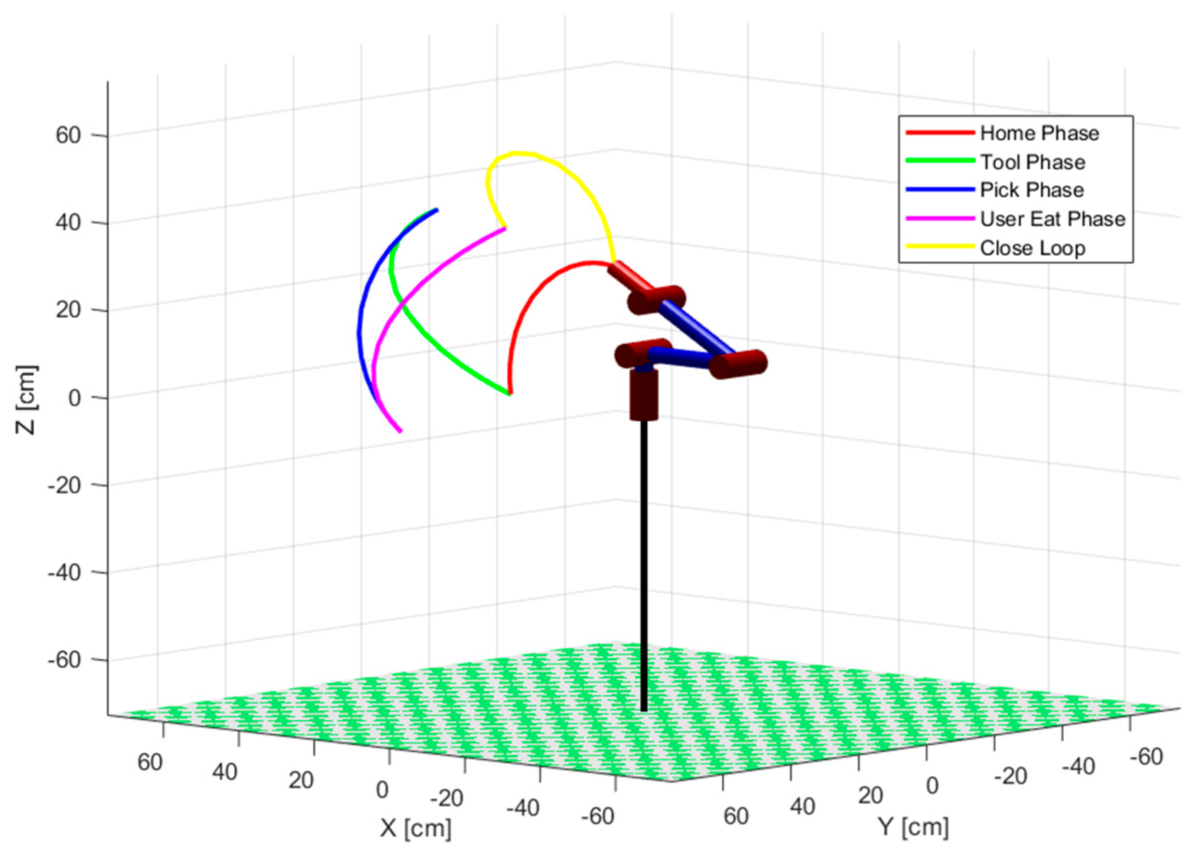
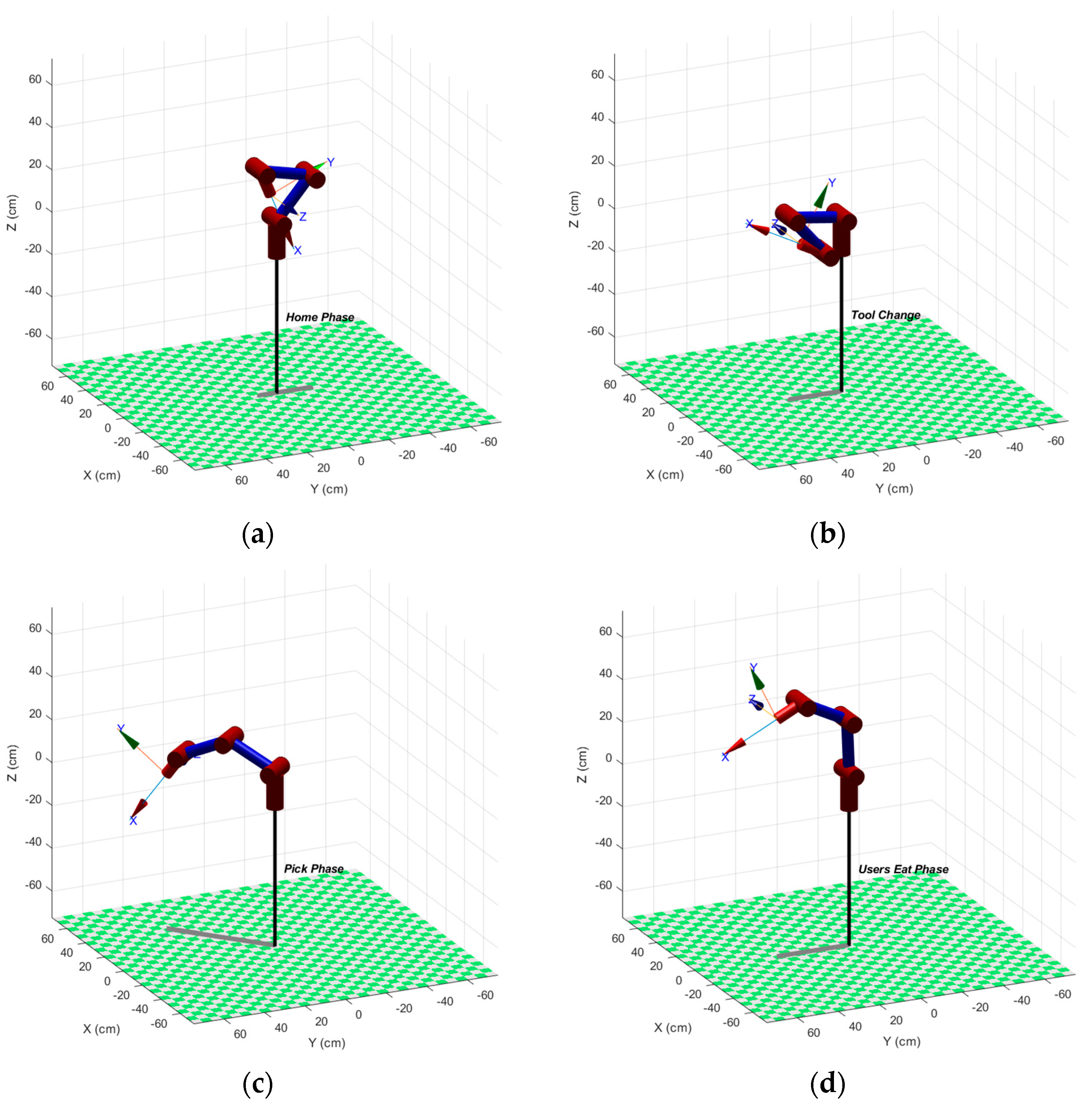
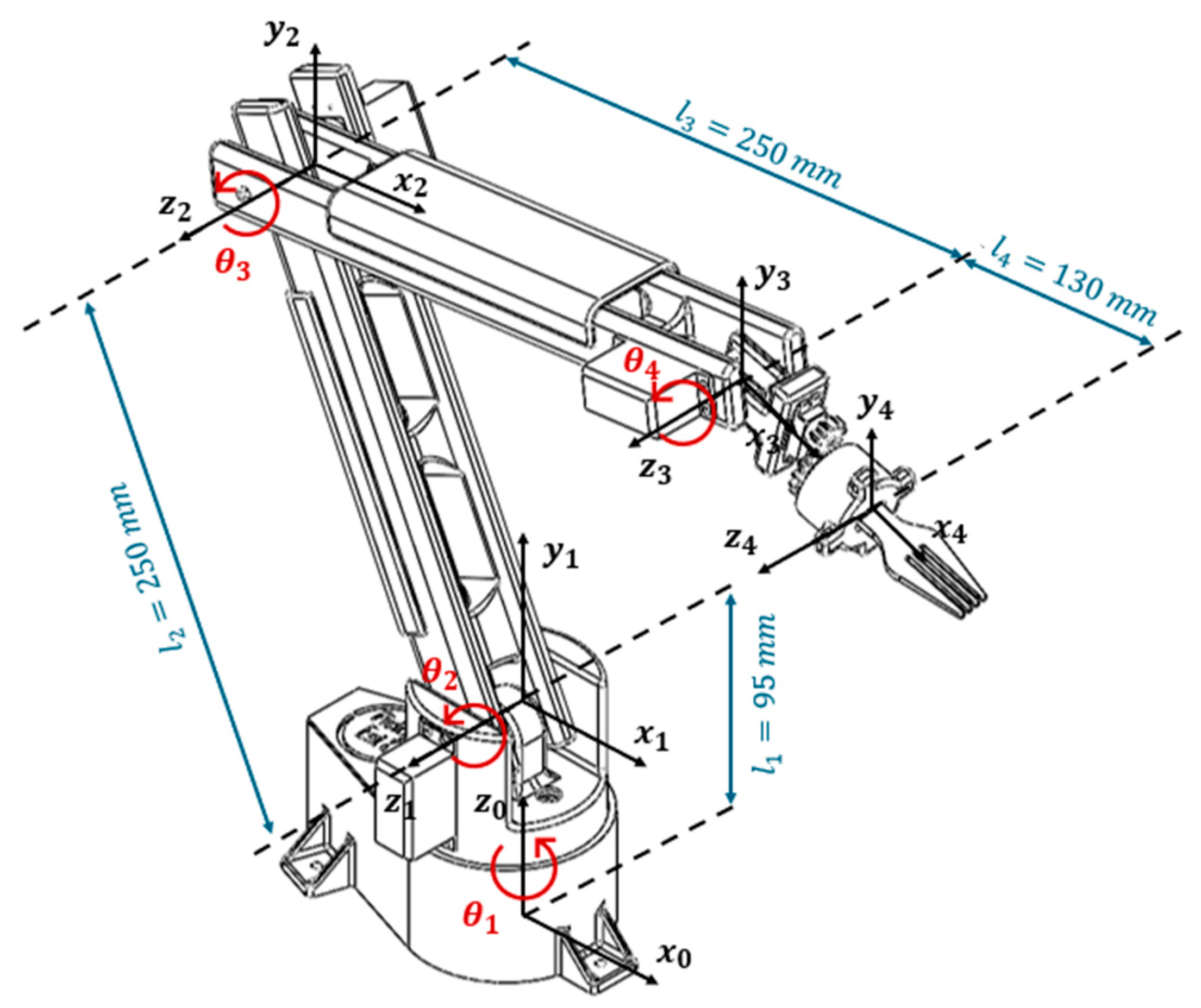
3. Kinematic Analysis

After conducting preliminary analyses regarding the fundamental movements to be performed, the necessary degrees of freedom, and the usable workspace, a detailed analysis of the motion of the examined system was carried out. This proves to be a crucial aspect for designing an effective control algorithm, aiming to accurately understand the position and orientation of the end-effector relative to the global reference system placed on the wheelchair.

3.1. Forward Kinematic Model

Using the manipulator schematisation, shown in Figure 9, and the Denavit–Hartenberg (D-H) convention, the kinematic analysis was performed and the parameters for each arm link were derived, as shown in Table 1.
The adoption of the D-H convention allowed for the establishment of the homogeneous transformation matrix T that correlates the transformation between the reference system (i − 1) and the reference system (i). In the present case, this matrix is equal to as follows:
T 4 0 = T 1 0 T 2 1 T 3 2 T 4 3 = c 1 c 234 c 1 s 234 s 1 c 1 ( l 2 c 2 + l 3 c 23 + l 4 c 234 ) s 1 c 234 s 1 s 234 c 1 s 1 ( l 2 c 2 + l 3 c 23 + l 4 c 234 ) s 234 c 234 0 l 1 + l 2 s 2 + l 3 s 23 + l 4 s 234 0 0 0 1
where s 1 = sin θ 1 , c 1 = cos θ 1 , s 2 = sin θ 2 , c 2 = cos θ 2 , s 23 = sin θ 2 + θ 3 , c 23 = cos θ 2 + θ 3 , s 234 = sin θ 2 + θ 3 + θ 4 , c 234 = sin θ 2 + θ 3 + θ 4 .
From the transformation matrix, the absolute coordinates of the end-effector with respect to the fixed frame are obtained as follows:
p x = cos θ 1 l 2 cos θ 2 + l 3 cos θ 2 + θ 3 + l 4 cos θ 2 + θ 3 + θ 4 p y = sin θ 1 l 2 cos θ 2 + l 3 cos θ 2 + θ 3 + l 4 cos θ 2 + θ 3 + θ 4 p z = l 1 + l 2 sin θ 2 + l 3 sin θ 2 + θ 3 + l 4 sin θ 2 + θ 3 + θ 4

3.2. Inverse Kinematic Model
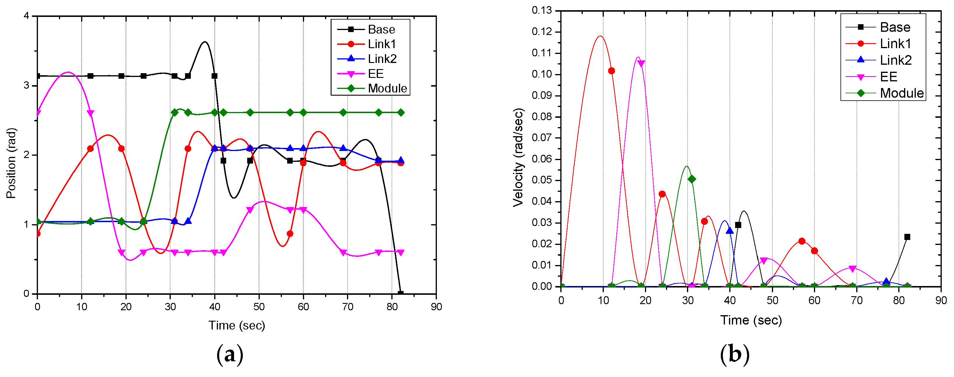
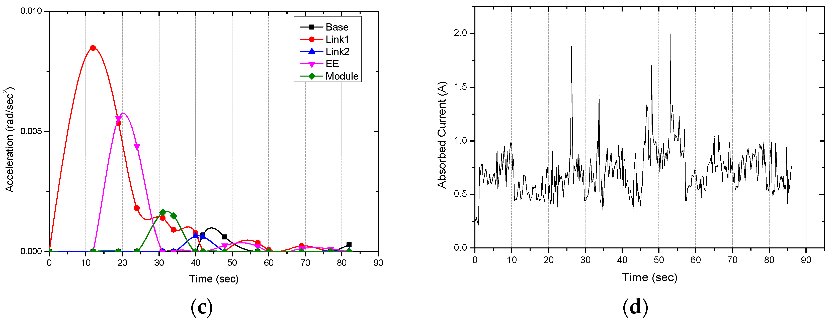
Once the functional relationships between the joint variables and the end-effector pose have been defined through forward kinematics, the next crucial step lies in solving the inverse kinematics. To perform such analyses, MATLAB software Version R2016 and the geometric method were employed to solve the system of nonlinear equations obtained by equating the transformation matrix T 4 0 (1) from forward kinematics with the known position of the end-effector expressed by the homogeneous matrix A (3).
T 4 0 q = A R ( q ) e b P q e b 0 1 = R P 0 1
The solution of the system of nonlinear equations enables to calculate the range of permissible joint angle values for the device, as shown in Table 2.
After the validation of the calculated positions within the work area, a MATLAB script was developed to generate the path planning, visible in Figure 10. This script uses a fifth-order polynomial to interpolate between different poses, aiming to generate smooth trajectories between configurations.
Specifically, the device transitions from the generic position to the resting configuration (Figure 11a), called the “Home Phase”. It then transitions from the Home Phase to the utensil change configuration, “Tool Phase” (Figure 11b), in which the utensils are detached/attached; from the Tool Phase to the “Pick Phase” (Figure 11c), reaching the required pose to pick up food from the dish; and finally, it moves from the dish to the patient’s mouth, called the “User Eat Phase” (Figure 11d).

4. Dynamic Analysis

The dynamic analysis of the examined device was carried out using the analytical Lagrange method. This is an energy-based approach that allows deriving the equations of dynamics in closed form, where the Lagrangian function calculated in the joint space serves as the difference between kinetic energy (T) and potential energy (U) and can be written as follows:
L θ , θ ˙ = T θ , θ ˙ U θ d d t L θ ˙ L θ = Q k
To estimate the dynamic effects, a simplified model of the device was developed, incorporating certain simplifying assumptions. Specifically, the rotation of the base was considered negligible, and the masses of each link, derived from the 3D CAD model of the device, were treated as concentrated at their respective centres of gravity. These considerations allowed for the derivation of expressions for kinetic and potential energy, as presented in Equation (5), once the coordinates of the centre of mass for each link and their respective velocities were obtained.
  T = T 1 + T 2 + T 3 = 1 2 m 1 v 1 2 + 1 2 I g θ ˙ 1 2 + 1 2 m 2 v 2 2 + 1 2 I g θ ˙ 2 2 + 1 2 m 3 v 3 2 + 1 2 I g θ ˙ 3 2 U = U 1 + U 2 + U 3 = m 1 g h 1 + m 2 g h 2 + m 3 g h 3
The substitution of these expressions (5) into Equation (4) allowed the determination of the Lagrangian function (6) and, through derivation, the Euler–Lagrange equation.
L = 1 2 m 1 v 1 2 + I g θ ˙ 1 2 + m 2 v 2 2 + I g θ ˙ 2 2 + m 3 v 3 2 + I g θ ˙ 3 2 g m 1 h 1 + m 2 h 2 + m 3 h 3
To solve the latter and determine the required torques for each motor to move the prototype under examination, MATLAB software was utilized. The obtained torque values, visible in Equation (7), were calculated considering the weight of each component and a precautionary food payload of 0.1 Kg.
τ 0 = τ 1 = F × r = 1.27   N m τ 2 = τ 3 = F × r = 0.46   N m
where the index “i” relating to τ i identifies, respectively, the torque required by the motor at the base to enable rotation ( τ 0 ), the motor at the first link ( τ 1 ), the motor at the second link ( τ 2 ) and finally the motor for the orientation of the end-effector ( τ 3 ).
The results obtained, illustrated in Equation 7, led to the selection of specific motors to guarantee the torque required to carry out each movement of the device. Two MG996R servomotors (Stall Torque: 9.4 kgf cm, 4.8 V, 500 mA, 0.17 s/60°) were used for the rotation of the base and the movement of the first link, two HITEC D485 HW servomotors (Stall Torque: 4.8 kgf cm, 4.8 V, 500 mA, 0.2 s/60°) were used for the movement of the second link and the end-effector, and finally, an SG90 micro servo motor (Stall Torque: 2.5 kgf cm, 4.8 V, 500 mA, 0.1 s/60°) was used for the release and/or coupling of the interchangeable tool module.
The analysis conducted and the readings of the potentiometers present in the servomotors made it possible to extract and plot useful information regarding the position (Figure 12a), speed (Figure 12b) and acceleration (Figure 12c) of the device. Furthermore, by processing the theoretical data and reading the data provided by a display connected to the step-down, it was possible to obtain the current values absorbed by each individual servomotor, visible in Figure 12d.

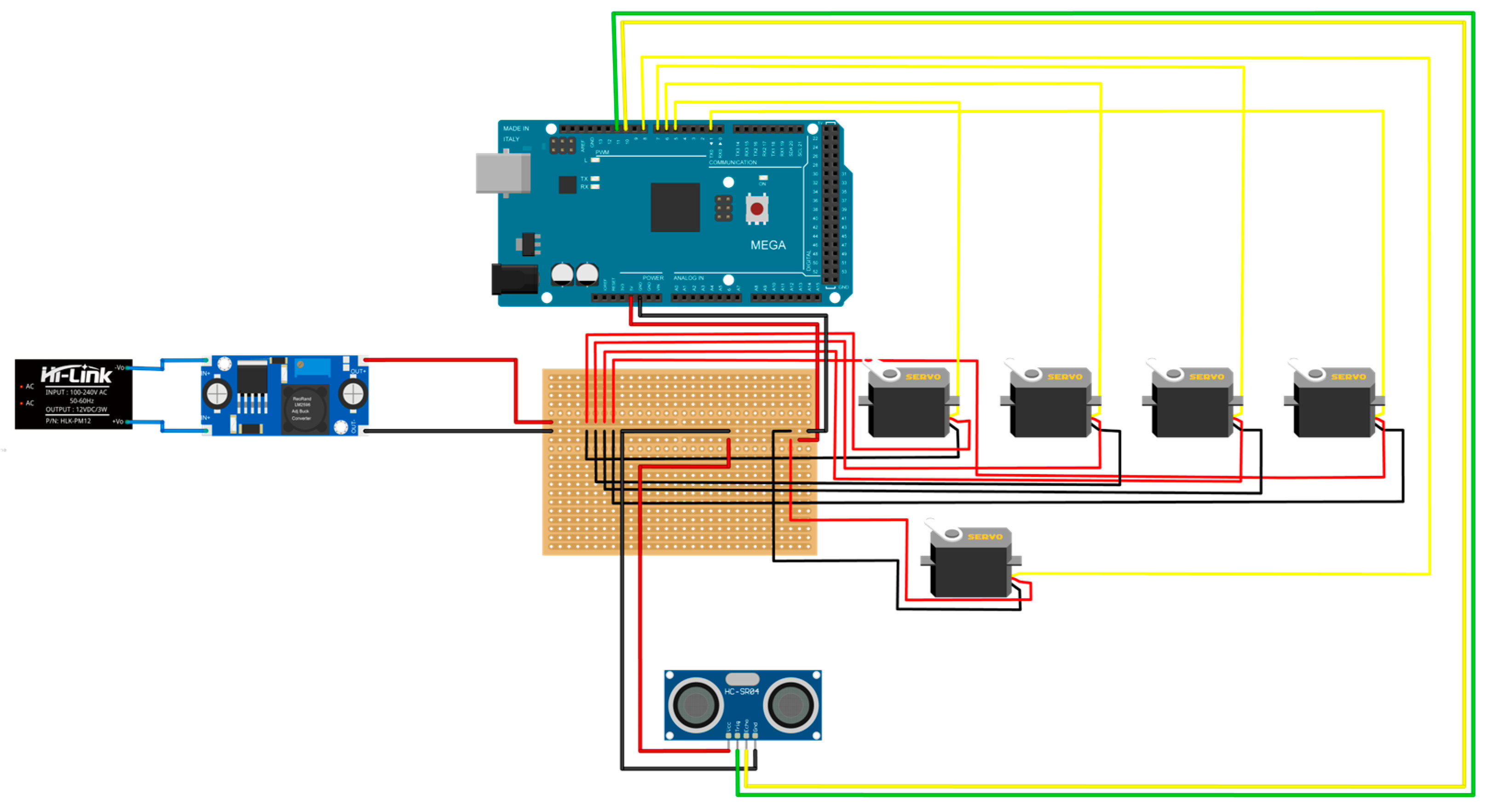
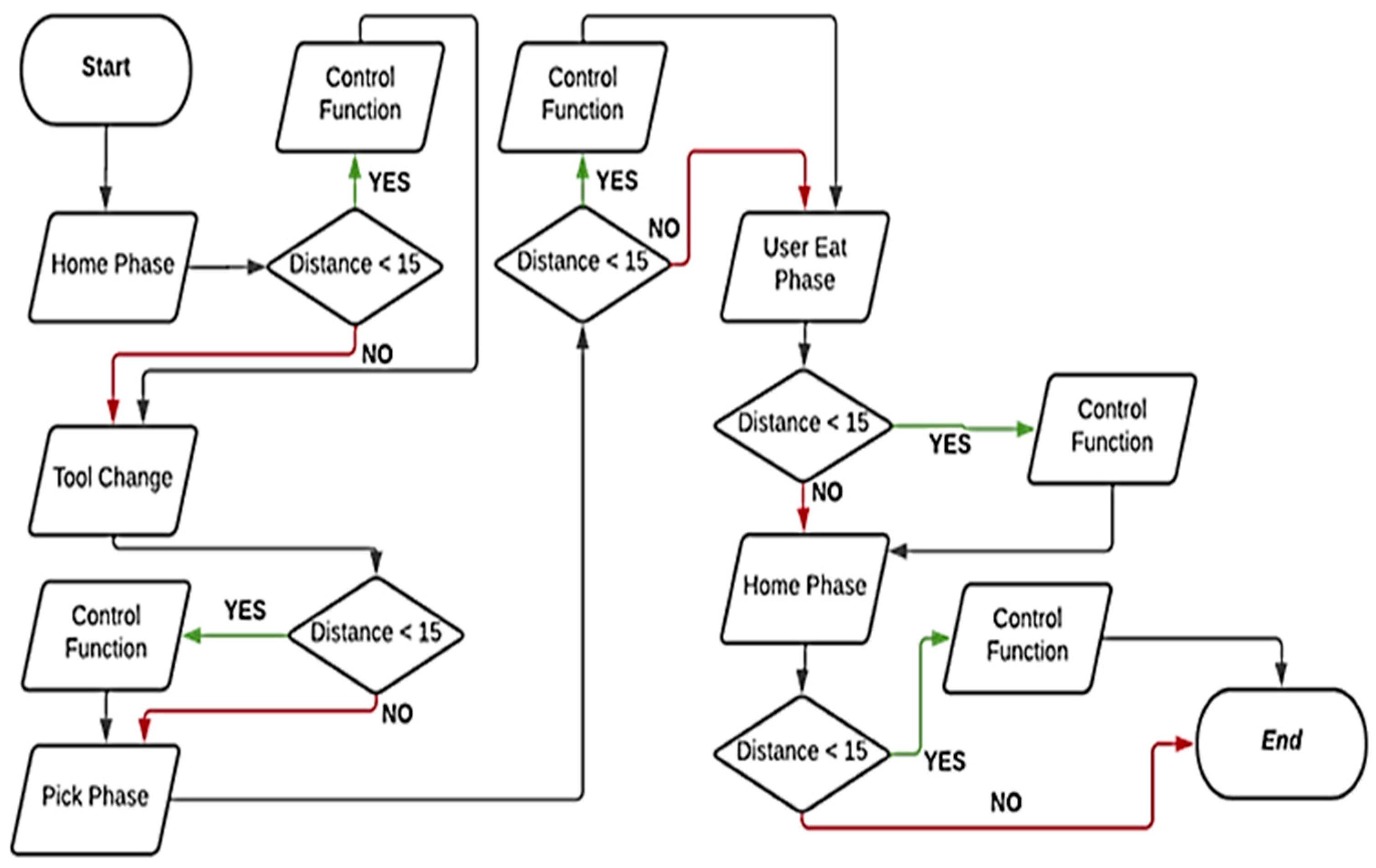
5. Control Architecture

The control architecture for the robotic device has been implemented using an Arduino MEGA, allowing all electronic components of the proposed device to be powered with the required operating voltages.
The electrical diagram, presented in Figure 13, is characterized by a transformer, placed inside the frame, to convert AC 220 V to DC 12 V and a step-down converter to lower the voltage to 7.5 V, optimal for the used servomotors. Specifically, two distinct power supply lines were created: the first line at 7.5 V, necessary to power the servomotors, and a second line at 5 V, which powers the micro servo and the ultrasonic sensor.
The introduction of the HC-SR04 ultrasonic sensor (operating voltage: 5 V DC, operating current: 15 mA, and ranging distance: 2 cm–4 m), mounted at the end of the end-effector, is of paramount importance as it ensures patient safety. In fact, the implemented control logic activates the sensor, causing the movement of the device to slow down if it detects an obstacle at a distance of less than 15 cm, or to stop immediately if the distance is less than 5 cm.
The implementation of the control logic represents the outcome of a thorough study of the needed function of the device. Moreover, user safety was taken in account during design. This process is shown in the flowchart in Figure 14, which is divided into four main functions, named accordingly with the phase explained in Section 3.2. In each of these functions there is a continuous loop operation during which
  • The values of the servomotor angles are constantly adjusted based on conducted analyses and the described path.
  • The sensor is called upon to check, during the movement of the device to bring the food to the mouth, for the presence or absence of obstacles.
During the “void Home” function, the device reaches the position described in the “Home Phase”, verifying the correct motor positions, and performing a self-calibration. The next “void ToolChange” function enables the manipulator to set the optimal configuration to attach or detach the tool module, the two links positions are adjusted accordingly to the required angle values. This function allows the entry and rotation of the L-shaped pin, either clockwise or counterclockwise, into the specific interchangeable module hole. Once the correct attachment/detachment of the tool module is verified, the “void ToolChange” ends, and the “void PhasePick” function starts. This function adjusts the motors’ angles to optimise food picking from the dish. Finally, the “void UsersEatPhase” function drives the manipulator to the final configuration, bringing the food 5 cm away from the patient’s mouth, a distance ensured by the presence of the sensor.

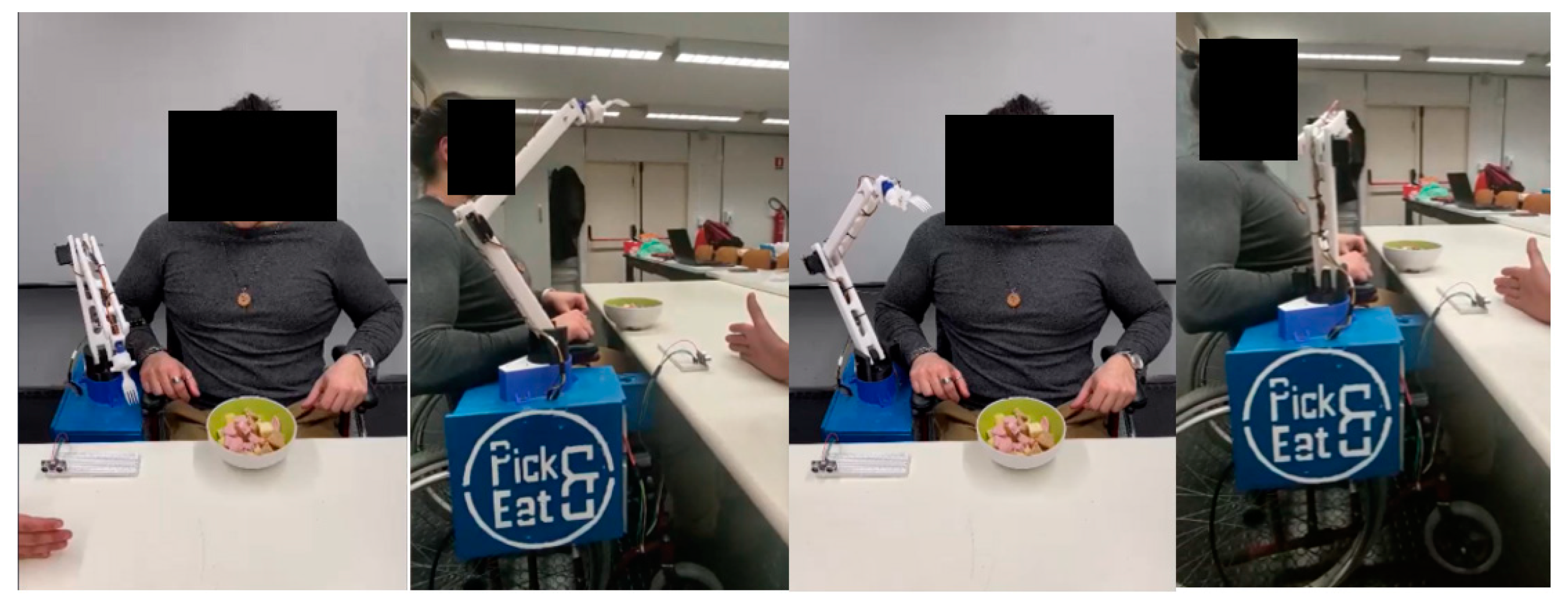
6. Preliminary Tests

To certify the safety, stability and functionality of the entire device, a series of rigorous and successive tests were conducted using a prototype developed in the mechatronics laboratory of the University of Calabria. After attaching the device to the wheelchair, several tests were conducted using the following main steps:
  • Verification of the stability of the frame placed at the side of the wheelchair.
  • Switching on the device, via a close switch, and checking the sensory feedback that is transmitted and stored in a laptop for further investigation.
  • Checking the efficiency of the ultrasonic sensor by placing a series of obstacles at different distances and confirming slowing down and/or stopping the motion if the reading gives a distance of between 15 cm and 5 cm, respectively, as visible in the frames in Figure 15.
  • Verification of the correct operation of the individual modules, by successively actuating the respective servomotors on the rotation of the device base, the movement of the first link, the second link, and the end-effector.
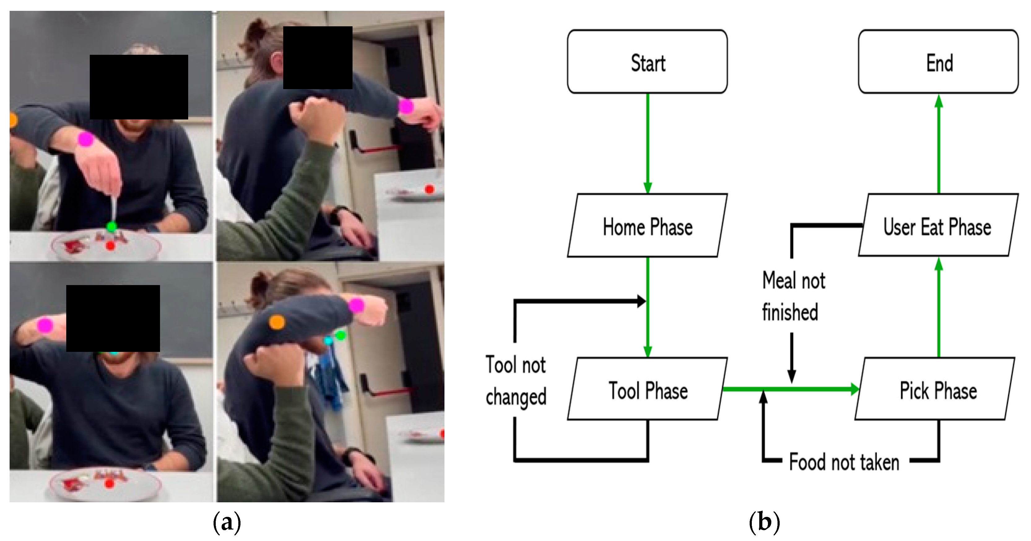
  • Verification of the various functions implemented and the consequent movements to achieve the optimum path, as well as the result of the analyses conducted.
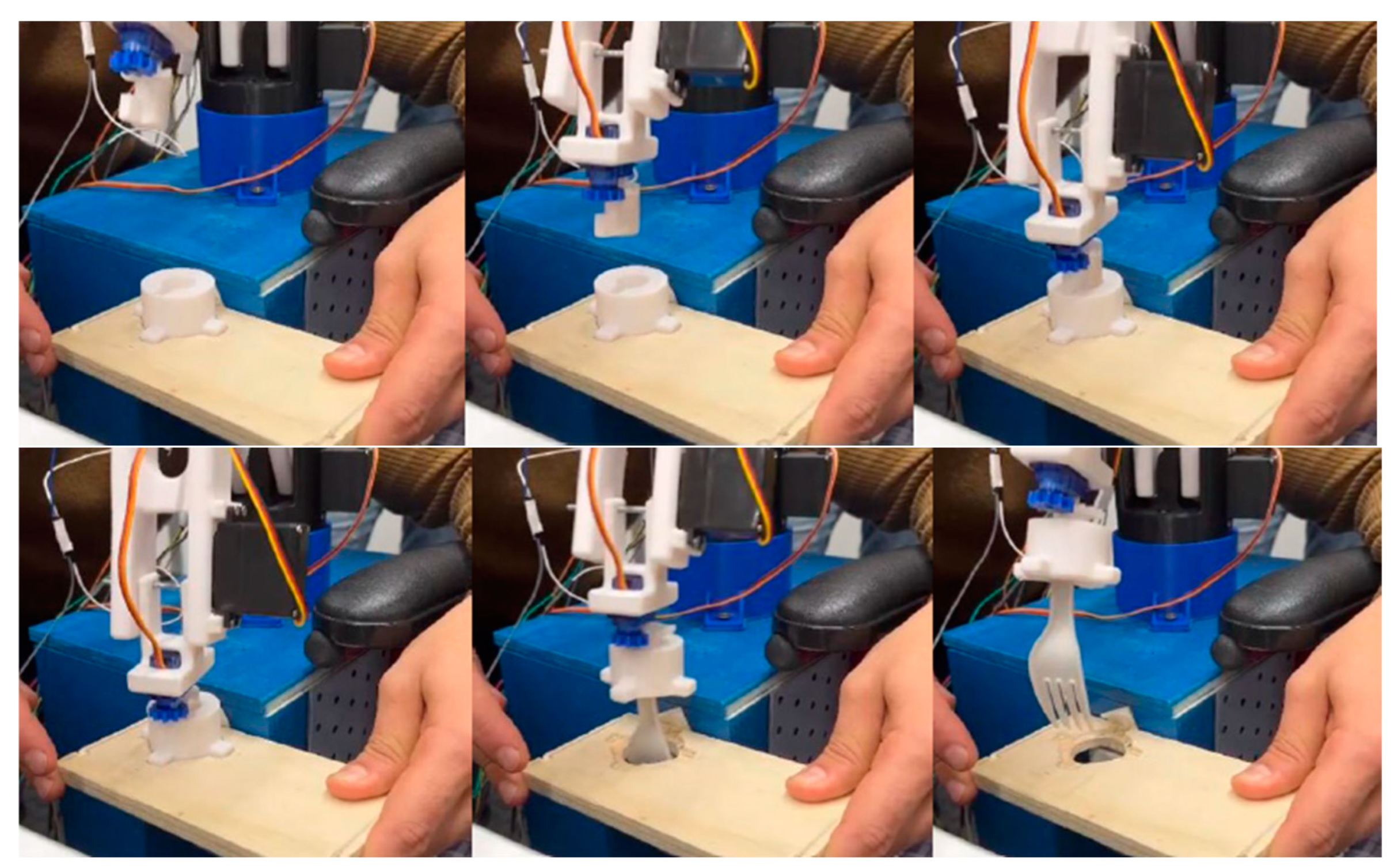
  • Check the correct release and/or coupling of the interchangeable tool module, with reference to the detail provided in Figure 16, to ensure the correct execution of the operation.
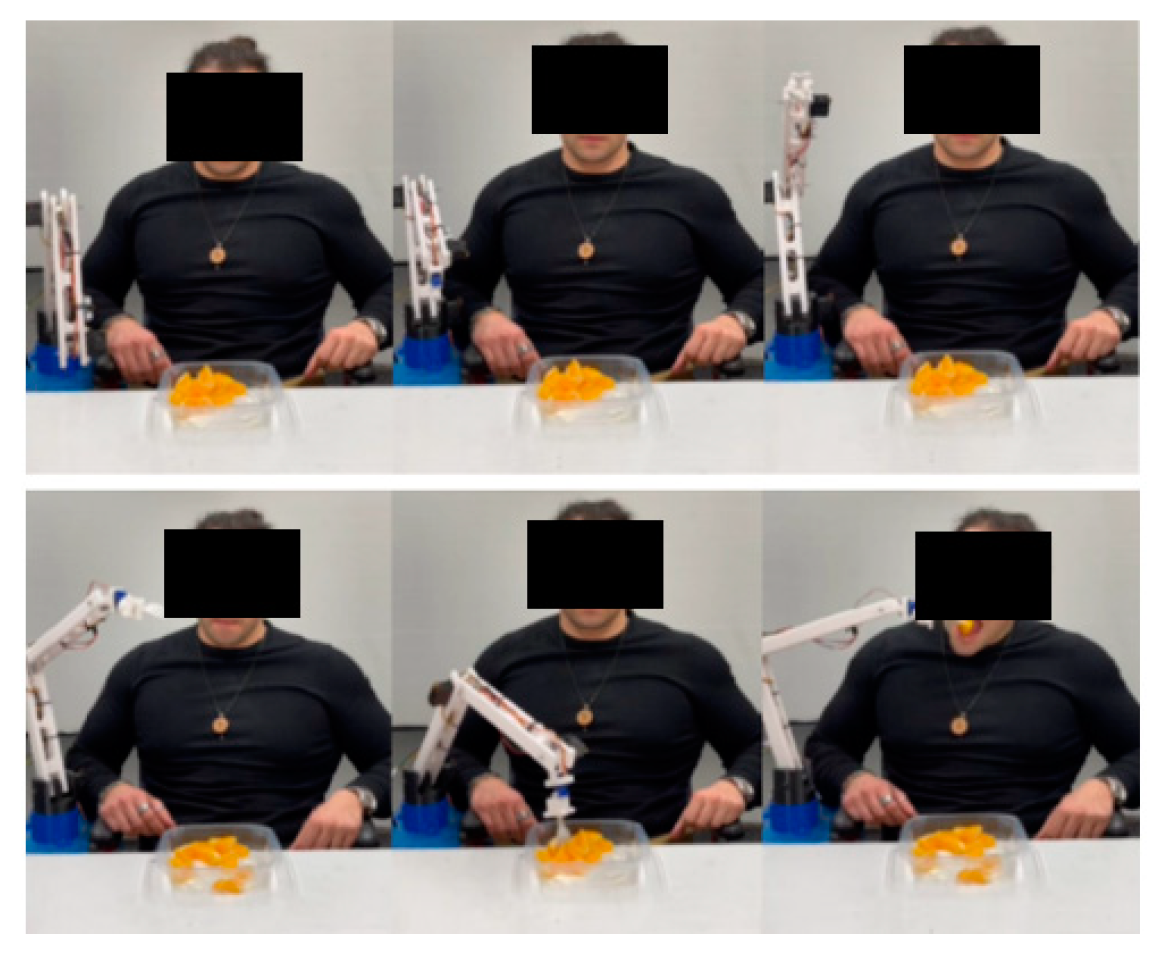
  • Verification of the correct operation of the entire path studied, verifying the effective taking of the food from the plate and the movement required to bring it to the user’s mouth.
  • Verification of the correct functioning of the device under different operating conditions.
Figure 17 and Figure 18 show, respectively, the front and side frames extracted from a video during the final phase of the tests carried out on the device. In particular, Figure 17 shows the frames related to the different phases of the design, while Figure 18 shows the detail of the release and/or attachment of the interchangeable tool module.
The tests conducted on the Pick&Eat device have successfully demonstrated the engineering feasibility of the proposed design that fulfils all predefined objectives and yielded excellent results consistent with the simulated values. The device was able to complete the task within an average time of 40 s. It is important to note that the purpose of this study was to introduce a conceptual design. Further investigations will be carried out in the future, aligning with previous simulation research efforts as reported in [28]. Additionally, future work will delve into control aspects, exploring impedance and admittance control for optimal robot–environment interaction, as proposed in works such as [29]. Attention will also be directed towards active learning of collision distance functionality, as suggested in [30,31]. Furthermore, we aim to explore different end-effectors, such as grippers capable of manipulating not only food but also a wide range of objects, as proposed by Fu et al. [32], Dong and Zhang [33], Carbone et al. [34], and Yao et al. [35]. Their collective work offers valuable insights into control strategies, motion planning, flexible grasping, grasp detection technology, and optimal design of robotic mechanisms, thereby opening multiple avenues for further enhancement of this research.

7. Conclusions

This paper presents the design of the new ‘Pick&Eat’ robotic system, a wheelchair-mounted robotic arm (WMRA), conceived to provide low-cost, safe, and reliable assistance to people with upper limb paralysis. This device aims to enable such individuals to independently perform one of the most basic, everyday activities, namely eating, while reducing dependence on operational assistance. The proposed device is based on an optimised design, characterised by a lightweight structure with high adaptability and portability, whose valid functioning has been preliminarily validated through laboratory tests. The preliminary results obtained and the feedback from beta users effectively attest to the feasibility, engineering effectiveness and potential of the proposed project, which is currently being tested. The system is expected to significantly improve the quality of life, psychological well-being, and social integration of users, while simultaneously reducing the workload of healthcare personnel. The ongoing experimentation will further consolidate the evidence on the validity and usefulness of the device, making it a valuable resource for the overall improvement of support for people with upper limb disabilities.

Author Contributions

Conceptualization and methodology S.L., L.G., V.R., A.S., F.L., E.M.C. and G.C.; investigation, S.L., L.G., V.R., S.M., A.S. and G.C; writing—original draft preparation, S.L., L.G., V.R., A.S. and G.C.; supervision, G.C. and D.P., funding G.C. and D.P. All authors have read and agreed to the published version of the manuscript.

Funding

This research has been supported by the project new frontiers in adaptive modular robotics for patient-centred medical rehabilitation—ASKLEPIOS, funded by European Union—NextGenerationEU and Romanian Government, under National Recovery and Resilience Plan for Romania, contract no. 760071/23.05.2023, code CF 121/15.11.2022, with Romanian Ministry of Research, Innovation and Digitalization, within Component 9, investment I8. We also acknowledge support of the Next Generation EU, PNRR MUR projects AGE-IT, DM 1557, 11.10.2022 and PNRR MUR project PE0000013-FAIR.

Informed Consent Statement

Informed consent was obtained from all subjects involved in the study.

Data Availability Statement

All the available data have been reported within this paper.

Conflicts of Interest

The authors declare no conflicts of interest.

References

  1. Sharkawy, A.-N. A survey on applications of human-robot interaction. Sens. Transducers 2021, 251, 19–27. Available online: https://www.sensorsportal.com/HTML/DIGEST/P_3221.htm (accessed on 19 September 2023).
  2. Italian Agency for Development of Cooperation. Available online: https://www.aics.gov.it/home-eng/fields/human-development/disability/ (accessed on 19 September 2023).
  3. World Health Organization. World Report on Ageing and Health. 2015. Available online: https://apps.who.int/iris/handle/10665/186463 (accessed on 19 September 2023).
  4. Atashzar, S.F.; Carriere, J.; Tavakoli, M. Review: How Can Intelligent Robots and Smart Mechatronic Modules Facilitate Remote Assessment, Assistance, and Rehabilitation for Isolated Adults with Neuro-Musculoskeletal Conditions? Front. Robot. AI 2021, 8, 610529. [Google Scholar] [CrossRef] [PubMed]
  5. Jiang, H.R.; Wachs, J.P.; Duerstock, B.S.; Pendergast, M. 3D Joystick for Robotic Arm Control by Individuals with High Level Spinal Cord Injuries. In Proceedings of the IEEE International Conference on Rehabilitation Robotics, Seattle, WA, USA, 24–26 June 2013. [Google Scholar]
  6. Alqasemi, R.M.; McCaffrey, E.J.; Edwards, K.D.; Dubey, R.V. Analysis, Evaluation and Development of Wheelchair-Mounted Robotic Arms. In Proceedings of the IEEE 9th International Conference on Rehabilitation Robotics, Chicago, IL, USA, 28 June–1 July 2005; pp. 469–472. [Google Scholar]
  7. Eftring, H.; Boschian, K. Technical results from manus user trials. In Proceedings of the ICORR ’99: International Conference on Rehabilitation Robotics, Stanford, CA, USA, 1–2 July 1999; pp. 136–141. [Google Scholar]
  8. Ranky, G.N.; Adamovich, S. Analysis of a commercial EEG device for the control of a robot arm. In Proceedings of the 2010 IEEE 36th Annual Northeast Bioengineering Conference (NEBEC), New York, NY, USA, 26–28 March 2010. [Google Scholar]
  9. Hillman, M.; Gammie, A. The Bath institute of medical engineering assistive robot. In Proceedings of the ICORR ’94, Wilmington, DE, USA, 14–15 June 1994; pp. 211–212. [Google Scholar]
  10. Chaves, E.; Koontz, A.; Garber, S.; Cooper, R.; Williams, A. Clinical Evaluation of a Wheelchair Mounted Robotic Arm. In Proceedings of the RESNA 26th International Annual Conference, Atlanta, GA, USA, 19–23 June 2003. [Google Scholar]
  11. Maheu, V.; Frappier, J.; Archambault, P.S.; Routhier, F. Evaluation of the JACO robotic arm: Clinico-economic study for powered wheelchair users with upper-extremity disabilities. In Proceedings of the 2011 IEEE International Conference on Rehabilitation Robotics, Zurich, Switzerland, 29 June–1 July 2011. [Google Scholar]
  12. Borboni, A.; Maddalena, M.; Rastegarpanah, A.; Saadat, M.; Aggogeri, F. Kinematic performance enhancement of wheelchair-mounted robotic arm by adding a linear drive. In Proceedings of the 2016 IEEE International Symposium on Medical Measurements and Applications (MeMeA), Benevento, Italy, 15–18 May 2016; pp. 1–6. [Google Scholar]
  13. Song, W.-K.; Lee, H.-Y.; Kim, J.-S.; Yoon, Y.-S. KARES: Intelligent rehabilitation robotic system for the disabled and the elderly. In Proceedings of the 20th Annual International Conference of the IEEE, Hong Kong, China, 1 November 1998. [Google Scholar]
  14. Volosyak, I.; Ivlev, O.; Graser, A. Rehabilitation robot FRIEND II—The general concept and current implementation. In Proceedings of the 9th International Conference on Rehabilitation Robotics, Chicago, IL, USA, 28 June–1 July 2005. [Google Scholar]
  15. Hillman, M.; Hagan, K.; Hagan, S.; Jepson, J.; Orpwood, R. The Weston wheelchair mounted assistive robot—The design story. Robotica 2002, 20, 125–132. [Google Scholar] [CrossRef]
  16. Fridenfalk, M.; Ulf, L.; Gunnar, B. Virtual prototyping and experience of modular robotics design based on user involvement. In Proceedings of the 5th European Conference for the Advancement of Assistive Technology, Düsseldorf, Germany, 1–4 November 1999. [Google Scholar]
  17. Perera, C.J.; Lalitharatne, T.D.; Kiguchi, K. EEG-controlled meal assistance robot with camera-based automatic mouth position tracking and mouth open detection. In Proceedings of the 2017 IEEE International Conference on Robotics and Automation (ICRA), Marina Bay Sands, Singapore, 29 May–3 June 2017; pp. 1760–1765. [Google Scholar]
  18. Candeias, A.; Rhodes, T.; Marques, M.; Costeira, J.P.; Veloso, M. Vision augmented robot feeding. In Computer Vision—ECCV 2018 Workshops; Lecture Notes in Computer Science; Springer Publishing Company: Cham, Switzerland, 2019; pp. 50–65. [Google Scholar]
  19. Park, D.; Hoshi, Y.; Mahajan, H.P.; Kim, H.K.; Erickson, Z.; Rogers, W.A.; Kemp, C.C. Active robot-assisted feeding with a general-purpose mobile manipulator: Design, evaluation, and lessons learned. Rob. Auton. Syst. 2020, 124, 103344. [Google Scholar] [CrossRef]
  20. Song, W.K.; Song, W.J.; Kim, Y.; Kim, J. Usability test of KNRC self-feeding robot. In Proceedings of the 2013 IEEE 13th International Conference on Rehabilitation Robotics (ICORR), Seattle, WA, USA, 24–26 June 2013; pp. 1–5. [Google Scholar]
  21. Bilyea, A.; Seth, N.; Nesathurai, S.; Abdullah, H.A. Robotic assistants in personal care: A scoping review. Med. Eng. Phys. 2017, 49, 1–6. [Google Scholar] [CrossRef] [PubMed]
  22. Rodriguez, L.A.; MacKenzie, L. Development and Analysis of a Wheelchair Mounted Robotic Manipulator. In Proceedings of the National Conference on Undergraduate Research (NCUR) 2016, University of Memphis, Memphis, TN, USA, 6–8 April 2017. [Google Scholar]
  23. Choi, J.; Gu, Z.; Lee, J.; Lee, I. Impedance matching control between a human arm and a haptic joystick for long-term. Robotica 2022, 40, 1880–1893. [Google Scholar] [CrossRef]
  24. Maciel, G.M.; Pinto, M.F.; da SJúnior, I.C.; Coelho, F.O.; Marcato, A.L.M.; Cruzeiro, M.M. Shared control methodology based on head positioning and vector fields for people with quadriplegia. Robotica 2022, 40, 348–364. [Google Scholar] [CrossRef]
  25. Calabrò, R.S.; Müller-Eising, C.; Diliberti, M.L.; Manuli, A.; Parrinello, F.; Rao, G.; Barone, V.; Civello, T. Who Will Pay for Robotic Rehabilitation? The Growing Need for a Cost-effectiveness Analysis. Innov. Clin. Neurosci. 2020, 17, 14–16. [Google Scholar]
  26. Mashrur, T.; Ghulam, Z.; French, G.; Abdullah, H.A. Assistive feeding robot for upper limb impairment—Testing and validation. Int. J. Adv. Robot. Syst. 2023, 20, 17298806231183571. [Google Scholar] [CrossRef]
  27. Leone, S.; Giunta, L.; Rino, V.; Mellace, S.; Sozzi, A.; Lago, F.; Curcio, E.M.; Pisla, D.; Carbone, G. Design of a Wheelchair-Mounted Arm for Mealtimes Assistance of Upper-Limb-Paralyzed Patients. In Advances in Mechanism and Machine Science; IFToMM WC 2023; Mechanisms and Machine Science; Okada, M., Ed.; Springer: Cham, Switzerland, 2023; Volume 148, pp. 919–927. [Google Scholar] [CrossRef]
  28. Curcio, E.M.; Carbone, G. Mechatronic design of a robot for upper limb rehabilitation at home. J. Bionic Eng. 2021, 18, 857–871. [Google Scholar] [CrossRef]
  29. Ye, D.; Yang, C.; Jiang, Y.; Zhang, H. Hybrid impedance and admittance control for optimal robot–environment interaction. Robotica 2023, 42, 510–535. [Google Scholar] [CrossRef]
  30. Kim, J.; Park, F.C. Active learning of the collision distance function for high-DOF multi-arm robot systems. Robotica 2024, 1–15, published online. [Google Scholar] [CrossRef]
  31. Yang, D.; Dong, L.; Dai, J.K. Collision avoidance trajectory planning for a dual-robot system: Using a modified APF method. Robotica 2024, 42, 846–863. [Google Scholar] [CrossRef]
  32. Fu, J.; Yu, Z.; Guo, Q.; Zheng, L.; Gan, D. A variable stiffness robotic gripper based on parallel beam with vision-based force sensing for flexible grasping. Robotica 2023, 1–19, published online. [Google Scholar] [CrossRef]
  33. Dong, M.; Zhang, J. A review of robotic grasp detection technology. Robotica 2023, 41, 3846–3885. [Google Scholar] [CrossRef]
  34. Carbone, G.; Gerding, E.C.; Corves, B.; Cafolla, D.; Russo, M.; Ceccarelli, M. Design of a Two-DOFs Driving Mechanism for a Motion-Assisted Finger Exoskeleton. Appl. Sci. 2020, 10, 2619. [Google Scholar] [CrossRef]
  35. Yao, S.; Ceccarelli, M.; Carbone, G.; Zhan, Q.; Lu, Z. Analysis and optimal design of an underactuated finger mechanism for LARM hand. Front. Mech. Eng. 2011, 6, 332. [Google Scholar] [CrossRef]
Figure 1. The proposed Pick&Eat design: (a) 3D cad model; (b) the built prototype of Pick&Eat at DIMEG, University of Calabria.
Robotics 13 00038 g001
Figure 2. Preliminary analysis conducted: (a) tracking the movement of the task to be performed with frontal view to the left and lateral view to the right (voluntary person in the image is one of the co-authors of this work); (b) logical State Diagram.
Robotics 13 00038 g002
Figure 3. Workspace and reachable points by the manipulator (note: in the figure hyphen (-) stands for a minus sign (−)).
Robotics 13 00038 g003
Figure 4. The proposed frame design for the Pick&Eat device: (a) 3D CAD model of the frame; (b) a CAD model of the removable panels; (c) a detailed view of the frame interior; and (d) the assembly of the frame onto the wheelchair.
Robotics 13 00038 g004
Figure 5. The design of the central body of the proposed Pick&Eat device: (a) 3D cad model of the central body; (b) exploded view of the CAD model of the central body base (1—Cover, 2—Driven gear wheel, 3—Bearing balls, 4—Ball housing, 5—Bearing Block, 6—Fixing base, 7—Servo Motor DM996R, 8—Servo Motor Disk, 9—Driving gear wheel).
Robotics 13 00038 g005
Figure 6. The design of the end-effector of the proposed Pick&Eat device: (a) 3D CAD model of the end-effector with interchangeable module and fork; (b) 3D CAD model of the interchangeable module with spoon; (c) 3D CAD model of the actuating mechanism: detail of the micro servo motor housing; (d) 3D CAD model of the actuating mechanism: detail of the gear wheel; (e) 3D CAD model of the actuating mechanism: detail of the cylindrical pin shaped with a mechanical tab; (f) front view of the 3D CAD model of the interchangeable module; and (g) rear view of the 3D CAD model of the interchangeable module.
Robotics 13 00038 g006
Figure 7. Topological analysis conducted on the link design.
Robotics 13 00038 g007
Figure 8. Static FEM analysis with a stress of 10 N: (a) von Mises stress; (b) static displacement.
Robotics 13 00038 g008
Figure 9. A schematisation of the manipulator.
Robotics 13 00038 g009
Figure 10. Path planning carried out: in red “Home Phase”, in green “Tool Phase”, in blue “Pick Phase”, in magenta “User Eat Phase” and in yellow “Close Loop” ((note: in the figure hyphen (-) stands for a minus sign (−)).
Robotics 13 00038 g010
Figure 11. Robot configurations to perform the complete task: (a) “Home Phase”, (b) “Tool Phase”, (c) “Pick Phase”, and (d) “User Eat Phase” (note: in the figure hyphen (-) stands for a minus sign (−)).
Robotics 13 00038 g011
Figure 12. Experimentally measured plots of the position (a), velocity (b), and acceleration (c) of the device and total absorbed electrical current about all servomotors (d).
Robotics 13 00038 g012aRobotics 13 00038 g012b
Figure 13. A scheme of the electrical wiring.
Robotics 13 00038 g013
Figure 14. A flowchart of the proposed control loop.
Robotics 13 00038 g014
Figure 15. Photo sequence of task execution: detail of correct sensor operation (Voluntary person in the image is one of the co-authors of this work).
Robotics 13 00038 g015
Figure 16. Photographic sequence of the task execution: detail of the correct engagement/disengagement of the interchangeable tool module.
Robotics 13 00038 g016
Figure 17. Photographic sequence of the task execution: front view of the different configurations to perform the task (Voluntary person in the image is one of the co-authors of this work).
Robotics 13 00038 g017
Figure 18. Photographic sequence of the task execution: side view of the detail of the release and/or attachment of the interchangeable tool module (voluntary person in the image is one of the co-authors of this work).
Robotics 13 00038 g018
Table 1. D-H parameter.
L i n k ( i ) a i α i d i θ i
1 0 π / 2 l 1 θ 1
2 l 2 0 0 θ 2
3 l 3 0 0 θ 3
4 l 4 0 0 θ 4
Table 2. Range of permissible values of joint angles for the device.
J o i n t   A n g l e s R a n g e   o f   V a l u e s
θ 1 0 ° 90 °
θ 2 30 ° 120 °
θ 3 60 ° 150 °
θ 4 30 ° 70 °
Disclaimer/Publisher’s Note: The statements, opinions and data contained in all publications are solely those of the individual author(s) and contributor(s) and not of MDPI and/or the editor(s). MDPI and/or the editor(s) disclaim responsibility for any injury to people or property resulting from any ideas, methods, instructions or products referred to in the content.

