Abstract
Controlling a laparoscopic camera during robotic surgery represents a multifaceted challenge, demanding considerable physical and cognitive exertion from operators. While manual control presents the advantage of enabling optimal viewing angles, it is offset by its taxing nature. In contrast, current autonomous camera systems offer predictability in tool tracking but are often rigid, lacking the adaptability of human operators. This research investigates the potential of two distinct network architectures: a dense neural network (DNN) and a recurrent network (RNN), both trained using a diverse dataset comprising autonomous and human-driven camera movements. A comparative assessment of network-controlled, autonomous, and human-operated camera systems is conducted to gauge network efficacies. While the dense neural network exhibits proficiency in basic tool tracking, it grapples with inherent architectural limitations that hinder its ability to master the camera’s zoom functionality. In stark contrast, the recurrent network excels, demonstrating a capacity to sufficiently replicate the behaviors exhibited by a mixture of both autonomous and human-operated methods. In total, 96.8% of the dense network predictions had up to a one-centimeter error when compared to the test datasets, while the recurrent network achieved a 100% sub-millimeter testing error. This paper trains and evaluates neural networks on autonomous and human behavior data for camera control.
1. Introduction
The advent of robotic surgical systems and their widespread use has changed the way surgery is performed. However, with this new technology comes the drawback of needing to view the surgical scene through a camera. This can lead to several problems, namely depth perception and camera control. In current clinical systems, the only way to control the laparoscopic camera is for the surgeon to press a clutch pedal or button which shifts the control over to the camera arm, move the camera, then resume work with the manipulator tools. This method of camera control requires the surgeon to divert their attention away from the surgery to move the camera. It might also result in one or both tools being out of the cameras’ field of view at some points due to suboptimal camera positioning. Recently, autonomous camera control systems have been developed that track the tools and keep them in the field of view. Such systems may increase patient safety significantly as the surgeon is always able to see the tools and does not need to interrupt the surgical flow to move the camera. However, they are limited in their capabilities and are unable to adapt to the surgeons’ needs. A third method has been developed for camera control: an external operator via joystick. This method shares many of the drawbacks of clutch control such as suboptimal views and additionally requires vocalization from the surgeon to communicate with the joystick-operator. However, it does outperform both the clutch and autonomous systems in terms of task execution times and does not narrow the camera focus on the tools [1]. It is difficult to articulate the ideal position for the endoscopic camera vocally or algorithmically.
To address this, an autonomous camera controller was developed using deep neural networks trained on combined datasets from rule-based and human-operated camera control methods. Deep neural networks have shown an impressive ability to process and generalize a large quantity of information in a particular setting. When properly trained, they can maximize and combine the advantages of rule-based autonomous and manual camera control while minimizing the drawbacks present in each method. This paper compares two network architectures with the existing system and evaluates their ability to find an optimal camera position.
2. Background
Making the laparoscopic camera autonomous has been the focus of many research groups over the years. The general capabilities of these systems involve tracking the manipulator arms using various methods [2]. In 2020, Eslamian et al. published an autocamera system that tracks tools using kinematic information from encoders to find the centroid of the tools and positions the camera such that the centroid is in the center of the camera image. The zoom level of the system is dependent on the distance between the tools, the movement of the tools, and time. The autocamera algorithm will move the camera in or out if the tools are stationary at a preset distance for a fixed amount of time [1]. Da Col et al. developed a similar system—SCAN (System for Camera Autonomous Navigation)—with the ability to track the tools using kinematics [3]. Garcia-Peraza-Herrera et al. created a system that uses the camera image to segment the tools in the field of view and track them. This system tracks one tool if only one is visible, and tracks both if both are visible. It also provides the ability to set a dominance factor to focus more on one tool over the other [4]. Elazzazi et al. extended autocamera systems to include a voice interface which allows the surgeon to vocally give commands and customize some basic system features [5]. While these systems do allow the operator to avoid context switching and focus solely on performing the surgery, they are limited by an explicit set of rules that must be hard coded into the system and often do not match what the operator would prefer.
Machine learning and deep neural networks are widely being researched as methods for surgical instrument tracking or segmentation. It was recently proven that the timing of the camera movements can be predicted using the instrument kinematics and artificial neural networks, but no camera control was applied [6]. Sarikaya et al. used deep convolutional networks to detect and localize the tools in the camera frame with 91% accuracy and a detection time of 0.103 s [7]. For actual camera control, Lu et al. developed the SuPer Deep framework that used a dual neural network approach to estimate the pose of the tools and create depth maps of deformable tissue. Both networks are variations of the ResNet CNN architecture; one network localizes the tools in the field of view and the other tracks and creates a point cloud depth map of the surrounding tissue [8]. Azqueta-Gavaldon et al. created a CycleGAN and U-Net based model for use on the MiroSurge surgical system. The authors used CycleGAN to generate images which were then fed to the U-Net model for segmentation [9]. Wagner et al. developed a cognitive task-specific camera viewpoint automation system with self-learning capabilities. The cognitive model incorporates perception, interpretation, and action. The environment is perceived through the endoscope image, and position information for the robot, end effectors, and camera arm. The study uses an ensemble of random forests to classify camera guidance quality as good, neutral, or poor, which is a classification system learned from the annotated training data. These ensembles are then used during inference to sample possible camera positions according to quality [10]. Li et al. utilized a GMM and YOLO vision model to extract domain knowledge from recorded surgical data for safe automatic laparoscope control. They developed a novel algorithm to find the optimal trajectory and target for the laparoscope and achieved proper field-of-view control. The authors successfully conducted experiments validating their algorithm on the dVRK [11]. Similarly, Liu et al. developed a real-time surgical tool segmentation model using YOLOv5 as the base. On the m2cai16-tool-locations dataset they achieved a 133 FPS inference speed with a 97.9% mean average precision [12]. These methods share the same advantages as the above autonomous approaches and are more adaptable to different situations, but they require dataset annotation, do not use human demonstrations for training, or suffer from high computational costs due to the use of convolutional networks. The methods discussed in this paper are computationally efficient while maintaining the advantages of rule-based automation and human-operated control. The networks are trained with data gathered from human demonstrations that can be used without annotation.
3. Materials and Methods
This section describes the da Vinci Surgical System and Research Kit (dVRK), the datasets used, the neural network architectures, and the dVRK integration. Python3 was used for the development of the neural networks, employing the Keras framework with a TensorFlow backend [13]. Many of the network hyperparameters given in this section are as they are simply because they are what produced the best results, and as such there is not an exploration of the network performances given using different hyperparameter values.
3.1. da Vinci Research Kit (dVRK)
The da Vinci Standard Surgical System used for this research consists of the tools or patient side manipulators (PSMs) (2×) and the endoscopic camera manipulator (ECM) (1×) as depicted in Figure 1a. The da Vinci Research Kit (dVRK) seen in Figure 1b provides the control hardware and associated Robot Operating System (ROS) Melodic software interfaces to control the the da Vinci Standard robot hardware [14]. This is performed by creating a network of nodes and topics using the framework provided using ROS. It also provides visualization of the three manipulators using ROS and RViz (as seen in Figure 2) which move in sync with their hardware counterparts. The visualization can be used independently of the hardware to develop and test software as well as for the playback of previously recorded manipulator data.
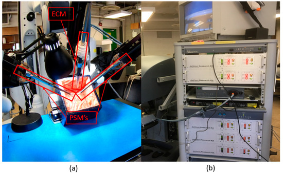
Figure 1.
Hardware configuration of the da Vinci Surgical System. (a) The instrument cart with the patient side manipulators (PSMs) and endoscopic camera manipulator (ECM) hardware. (b) The dVRK hardware control tower.
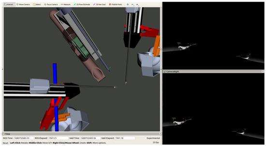
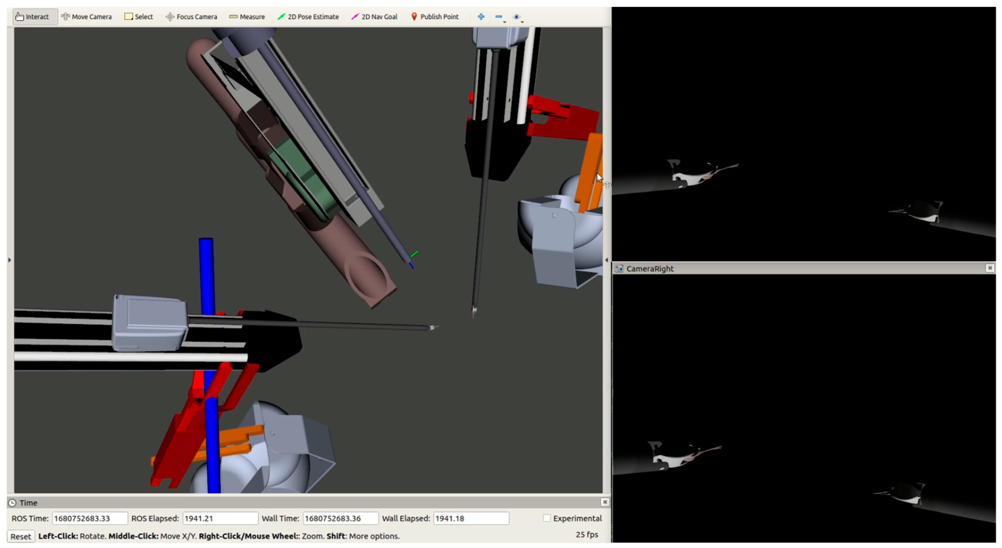
Figure 2.
RViz view of the PSMs and ECM, and the camera views from the left (top) and right (bottom) cameras of the ECM.
3.2. Data
The data used to train and evaluate the neural networks were recorded from a user-study conducted by our lab and published by Eslamian et al. [1]. The 20-subject study had the da Vinci operators move a wire across a breadboard while the camera was controlled via one of three methods: clutch control using the da Vinci operator, an external human-operated joystick, and the previously mentioned autonomous algorithm (autocamera) by Eslamian et al. which tracks the midpoint of the tools. One camera operator (for joystick control) was well-trained and chosen so that there was a consistent operator across all 20 participants. The task was chosen such that it would require dexterous movement of the tools and handling of suture-like material, thereby closely mimicking a surgical suturing task. (Please reference supplementary materials).
The results of the study report that the joystick-operated camera control method narrowly edged out the autonomous control method in terms of timing but that the autonomous method was preferred for its ability to track the tools. Both the human-operated joystick and autonomous methods outperformed the clutch-controlled camera. The study demonstrated notable benefits of the predominant camera control techniques. Specifically, the autonomous system excelled in maintaining tool visibility, while the joystick-based human operation used task awareness, resulting in improved movement timing [1]. Consequently, the decision was made to train the networks using a hybrid approach, incorporating data from both autonomous and joystick camera control methods. As such, the training data comprised a 70:30 split of autonomous–joystick. Clutch control data were excluded due to it being clearly outperformed by the other methods and offering no distinct advantages. The relevant data captured at 100 Hz contained only the 3D cartesian tooltip and camera positions obtained via forward kinematics. The tool and camera positions are in respect to the base of each manipulator arm as seen in Figure 3. The orientation of the manipulators was not used as it has no impact on how the camera controller positions the camera. The data underwent no normalization or standardization so as to not distort the spatial correlations between the datapoints.
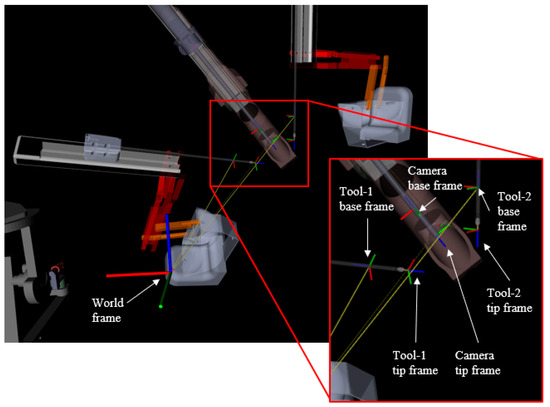
Figure 3.
An RViz visualization of the da Vinci instrument cart showing the tool base/tip frames, the camera base/tip frames, and the world frame.
3.3. Dense Neural Network
Dense neural networks consist of layers of neurons where each neuron is connected to every neuron in the previous and next layer. In this case, dense networks provide a simple baseline to compare with more complicated models. The dense network trained for this study consisted of an input layer with six neurons (xyz of each PSM), three hidden layers with two-hundred and fifty-six neurons, and one output layer with three neurons (xyz position of the ECM). All hidden layer neurons had the rectified linear unit (ReLU) activation function, and the network had a parameter count of 134,147. The network input was a tensor of dimensions (batch size, features dimension), or specific to our case (batch size, 6), where the features were the two (x, y, z) coordinates of the PSMs. The output of the network was the coordinates of the ECM. For training, mini-batch stochastic gradient descent (SGD) was used with a batch size of 50 and the Adam optimizer with a learning rate of 1 × 10⁻⁵ and mean squared error (MSE) loss. The over one million data points were split into 70:20:10 for training, validation, and testing. To prevent overfitting, early stopping based on monitoring validation loss was used. The patience to stop when the monitor sees no improvement in loss was set to ten epochs.
3.4. Recurrent Neural Network
The dense model used in this study processes each timestep individually, with no memory of previous timesteps. On the other hand, a recurrent neural network (RNN) processes the input step-by-step but stores states between timesteps and uses them to influence the output. Since the data are sampled at 100 Hz, the difference in positions between timesteps will never be too large, making this feature prime for exploitation by the RNN. Moreover, the ECM mechanically zooms after an idle period of 250 ms, making the recurrent units especially suited to imitate this behaviour. The gated recurrent unit (GRU) is the RNN cell used; the GRU has states and gates with learnable weights, which operate on and are updated by the current input and information carried over from previous timesteps [15,16]. It was chosen because it has less parameters than other RNN cells and is better suited for smaller timesteps.
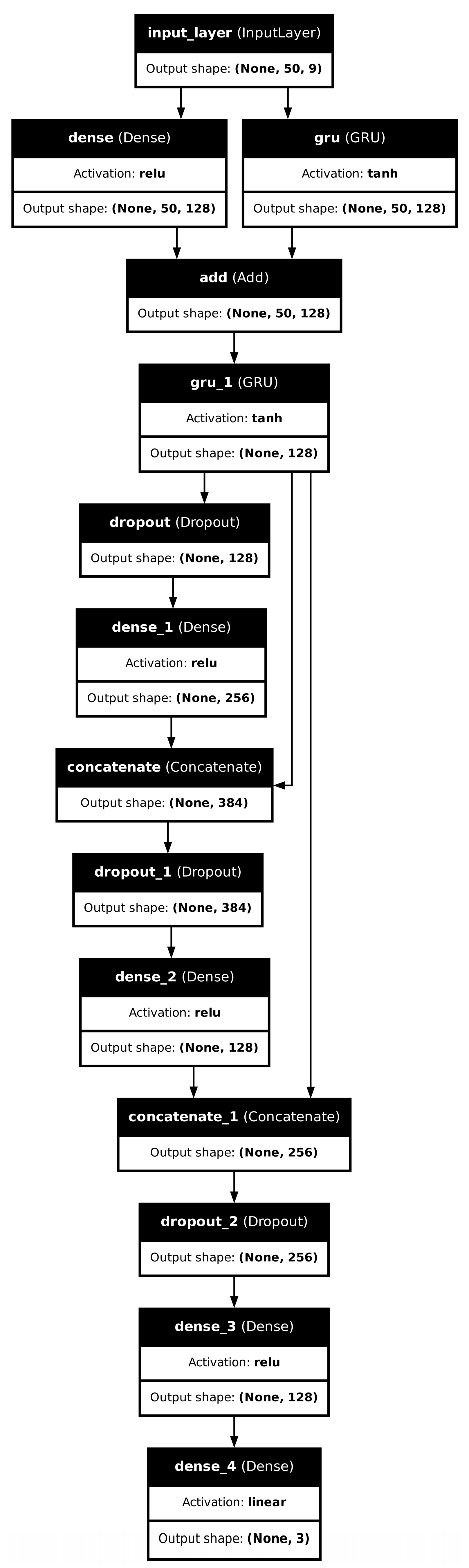
The input tensor to the network had dimensions (batch size, timesteps, features dimension) or, specific to our case, a tensor of shape (batch size, 50, 9) where the reccurent unit processed 50 timesteps and nine features: 2 PSM and 1 ECM 3D cartesian positions. The 50 timestep inputs to the network were cascadedly sampled from the dataset, treating it as a sequence prediction problem. The timesteps were chosen based on the 250 millisecond time taken for the autonomous system to zoom, with some buffer included. The actual architecture of the network can be found in Figure A1 and Table 1.

Table 1.
GRU network architecture showing the layers, activations, recurrent activations (when relevant), and number of parameters.
Firstly, the tensor input is fed to a dense layer and a GRU layer separately; both of these layers return tensors of the same dimension, so their results can be added. There are also skip connections and concatenation layers present downstream. These are there for better gradient flow—especially the residual connection from gru_1 to concatenate_1, and the hypothesis that the network will fit the data better than a sequential architecture. The output is the coordinates for the ECM.
The RNN was trained with similar parameters to the dense-only network, with mini-batch SGD, an Adam optimizer with MSE loss, and a learning rate of 1 × 10⁻⁵ The train, validation, testing split for the 1M+ data points was 60:30:10.
3.5. da Vinci Researck Kit (dVRK) Integration
The integration of the neural networks and dVRK was created to allow modularity in the interface. First, the forward kinematics are computed in the camera control class, and the pose of the tools is obtained. From this, the positions are extracted and sent to the neural network class via a ROS service call. If the selected network is the dense network, then the neural network class immediately feeds the data as inputs to the network and returns the output camera position via the ROS service response. If the selected network is the recurrent network, then the class will fill a buffer with the requisite timesteps before feeding it into the network and obtaining the camera position, which is then returned to the camera controller.
Once the Cartesian camera positions have been returned, the camera controller uses the Rodrigues Rotation Formula to calculate the rotation matrix between the returned position and the known camera trocar point (also referred to as the base frame seen in Figure 3). The rotation matrix is combined with the returned Cartesian position to obtain the transformation matrix which is then used to compute the inverse kinematics (IK). The joint angles from the IK are given to the dVRK software (dVRK version 1.4.0/CISST version 1.0.8) to move the camera.
To find the transformation matrix (T) necessary for the inverse kinematics calculations, the desired orientation (Rdesired) of the ECM must first be computed. The keyhole (k) of the system is the trocar point around which the ECM rotates (also referred to as the base frame in Figure 3), and the desired position (p) is the output of the neural networks. With this information, a vector (g) is calculated to define the direction that the ECM should be pointing.
The current direction that the ECM is pointing (c) is the difference between the ECM’s current position (b), as calculated using forward kinematics, and the keyhole.
Next are a series of calculations to determine the angle (θ) between the current (c) and the desired (g) ECM directions, and to calculate the unit vector (u) about which that rotation takes place.
The skew–symmetric matrix (U) of u is defined below as well.
Using the above calculations, the rotation matrix (Rcg) between the current (c) and desired (g) vectors is determined as follows:
The desired ECM rotation matrix can now be computed using the current orientation (Rcurrent) as obtained from forward kinematics and the previously calculated Rcg.
Finally, the transformation matrix can be built as follows:
The camera control and neural network classes are separated to allow full modularity and ease with respect to the network loaded in. Any network with any inputs and outputs can be loaded in, if what is given from and returned to the camera control class remains the same—namely, the coordinates of the PSMs and the ECM.
4. Results
The performance of the neural networks was evaluated in four ways: first, using the train–validation loss graphs; second, using direct comparison of the Euclidean distance between the network-predicted value and the value from the test portion of the dataset; third, using the visualization of the predicted value and the dataset’s ECM and PSM values; and fourth, by having the neural network control the camera and evaluating based on the views from the camera itself and by counting the number of frames in which the tools were in/out of view. To ensure a fair comparison during the fourth evaluation, a sequence of PSM motions were pre-recorded and played back as necessary for each method of ECM control. The experiments were performed in simulation to allow for an effective and accurate interpretation of the data, methods, and results.
4.1. Dense Neural Network
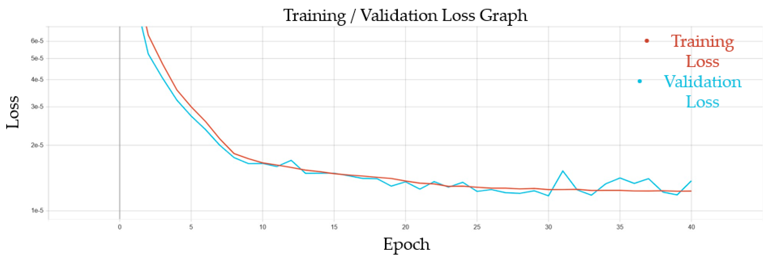
The train–validation loss graph showed the exponential decay of the loss value until both losses plateaued just above 1 × 10⁻⁵ after 40 epochs, after which training was stopped as seen in Figure 4. This indicated no overfitting and a good generalizability for the network.

Figure 4.
Loss graph for the fully connected neural network showing the training and validation losses over 40 epochs. The red line is the training loss, and the blue line is the validation loss. The losses plateau at a value of 1 × 10⁻⁵ after 40 epochs.
However, Figure 5 shows that when evaluated against an unseen dataset, the Euclidean distance between the dense network’s predicted position and the dataset-given position can be as high as 0–1 cm for 96.8% of the test data and as low as 10 mm for 12.3%. Further evaluation and visualization of the 3D positions in Rviz, such as in Figure 6 indicate that this error is due to the temporal nature of the ECM’s mechanical zoom in the autocamera algorithm. Given that the manipulators of da Vinci all have a remote center of motion, there is only one possible joint configuration that allows the ECM to be in the predicted position. The visualization results suggest that despite the difference between the predicted and dataset-given values, the network-predicted ECM positions are still valid such that the PSMs may be in the camera view.
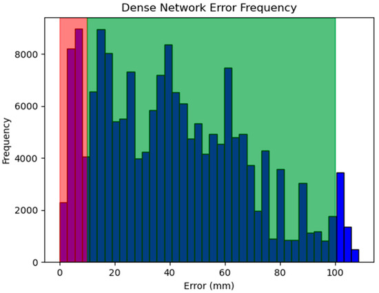
Figure 5.
Histogram of the dense network error frequency. The error observed here is the Euclidean distance in millimeters between the predicted and dataset-given values for a sample of test data. The bars highlighted in red indicate the number of predictions that were at or below the 10 mm error tolerance (21,851 frames), green is at or below 1 cm (171,953 frames), and total 177,686 frames.
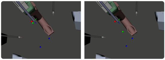
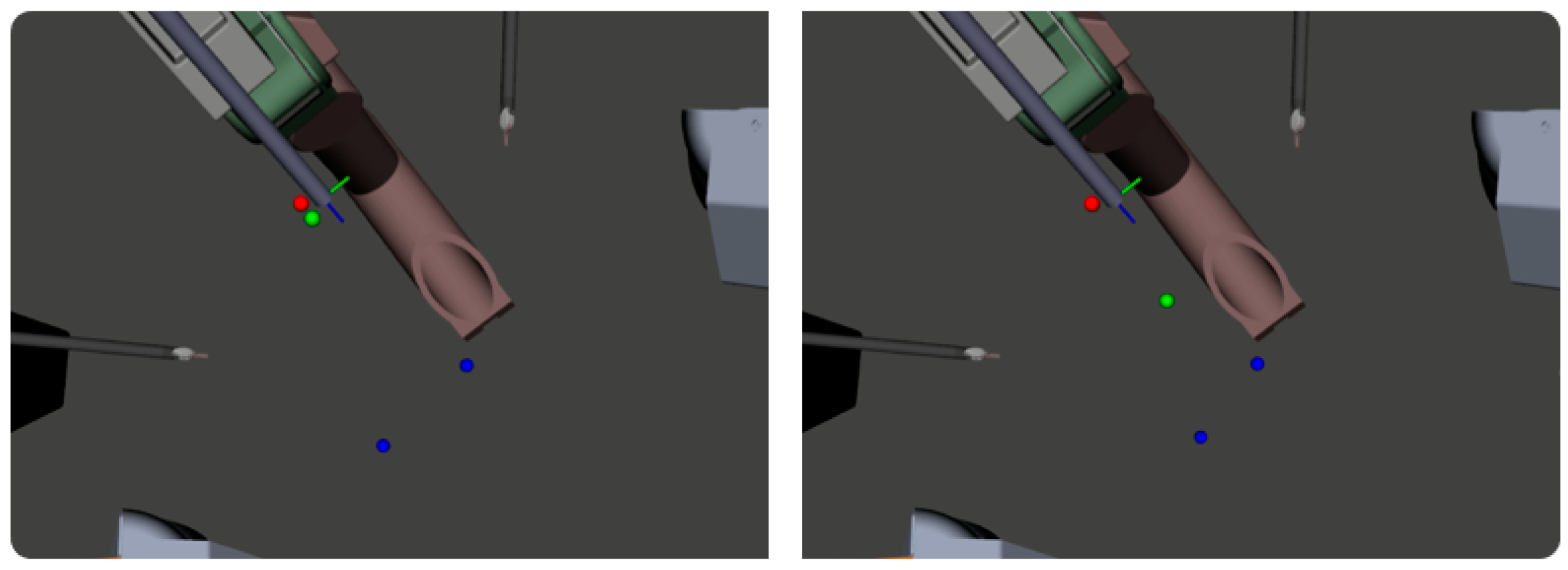
Figure 6.
A visualization of the network-predicted ECM position (green), the dataset-given ECM position (red), and the dataset-given PSM positions (blue). Note that the actual ECM/PSMs are only shown for context to allow an uninterrupted view of the predicted/dataset positions.
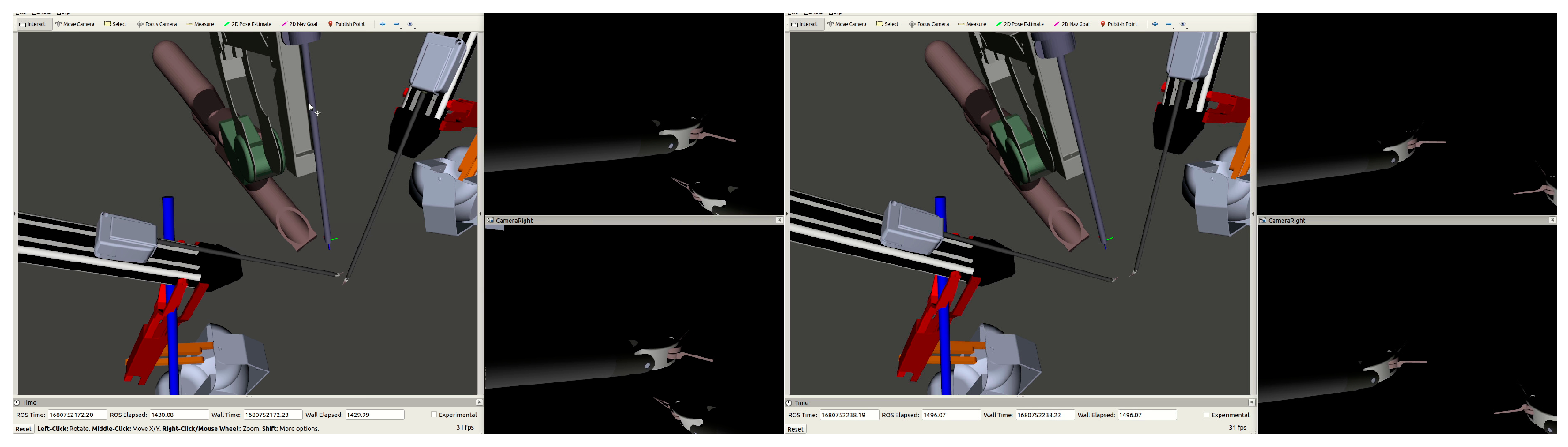
A full system evaluation with pre-recorded PSM motions was performed and ECM control was given to the dense network. The analysis results had 1333 of 1333 frames with at least one tool in view. The image stills from the full system test in Figure 7 show that the dense network is capable of learning to position the ECM such that the PSMs remain in the field of view, but that it will often zoom in more than is necessary. The narrow focus results in a loss of situational awareness and can be considered detrimental to the operation.
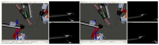
Figure 7.
Two stills of a dense-network-controlled ECM at different PSM positions. The left pane of each image shows the relative positions of the ECM and the PSMs, while the top and bottom panes on the right are images from the left and right cameras of the ECM, respectively.
4.2. Recurrent Neural Network
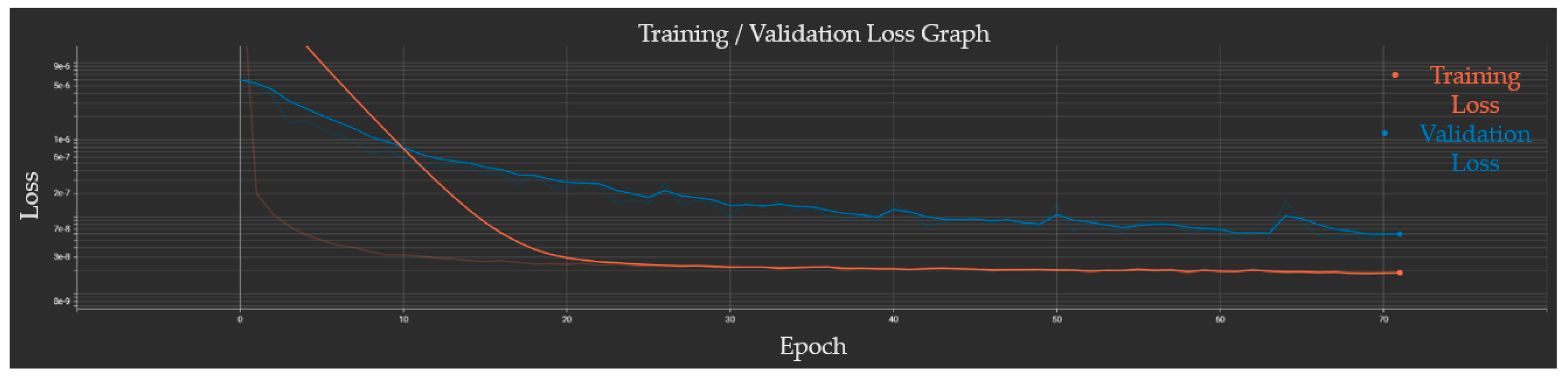
The train–validation loss graph for the GRU network similarly indicated good network generalizability. The training loss plateaued at a value of 2 × 10⁻⁸ while the validation loss plateaued at 6 × 10⁻⁸ after 72 epochs (due to having no improvements over the last 10 epochs) as seen in Figure 8. The validation loss for the recurrent network is nearly 1000 times better than that of the dense network, suggesting that the GRU will perform better overall.

Figure 8.
GRU network train–validation loss graph. The orange and blue lines are, respectively, the training and validation losses. The training loss plateaued at a value of 2 × 10⁻⁸, and the validation loss plateaued at 6 × 10⁻⁸ after 72 epochs.
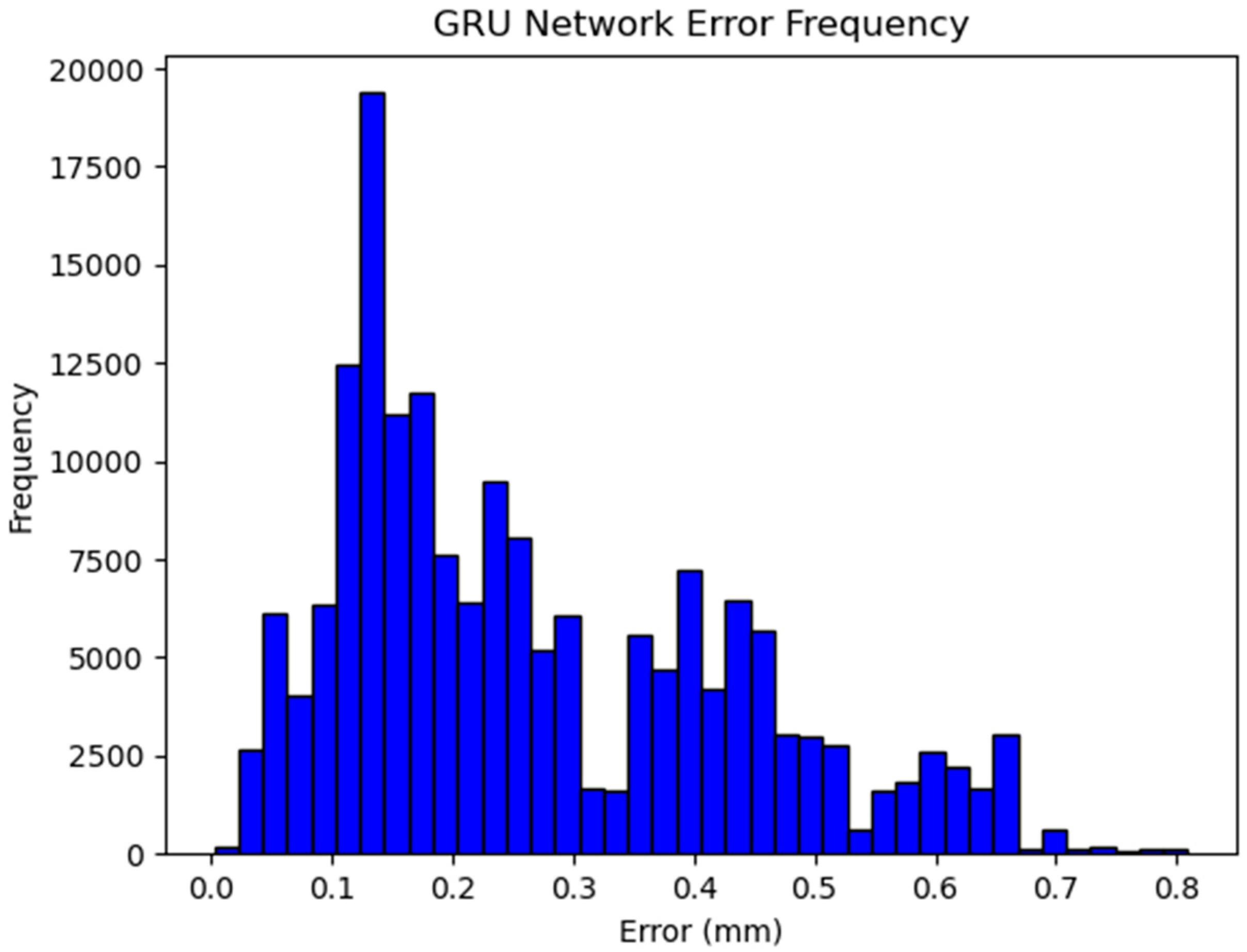
Figure 9 shows the difference in the Euclidean distance between the GRU network-predicted ECM positions and the dataset-given ECM positions for the same test dataset as in Figure 5. The GRU achieved sub-millimeter accuracy for 100% of the test data, suggesting an ability to learn the temporal aspects of the autocamera’s zoom algorithm with respect to the mechanical zoom of the ECM. This is further supported by the visualization of the GRU-predicted ECM position along with the dataset-given positions of the ECM and PSMs seen in Figure 10. The full system test resulted in at least one tool being in view for 1282 of the 1354 frames, with the tools being out-of-view for 72 frames. Upon further analysis, it was found that those frames all corresponded with the time needed to fill the timestep buffer for the GRU, during which it would not be providing outputs for the camera position. Image stills from the test as seen in Figure 11 show that the GRU keeps both PSMs in the field-of-view without zooming in too closely when not needed, providing a significantly better view of the scene.
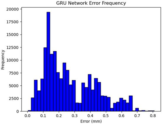
Figure 9.
Histogram of the GRU network error frequency. The error observed here is the Euclidean distance in millimeters between the predicted and dataset-given values for a sample of test data.
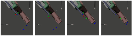
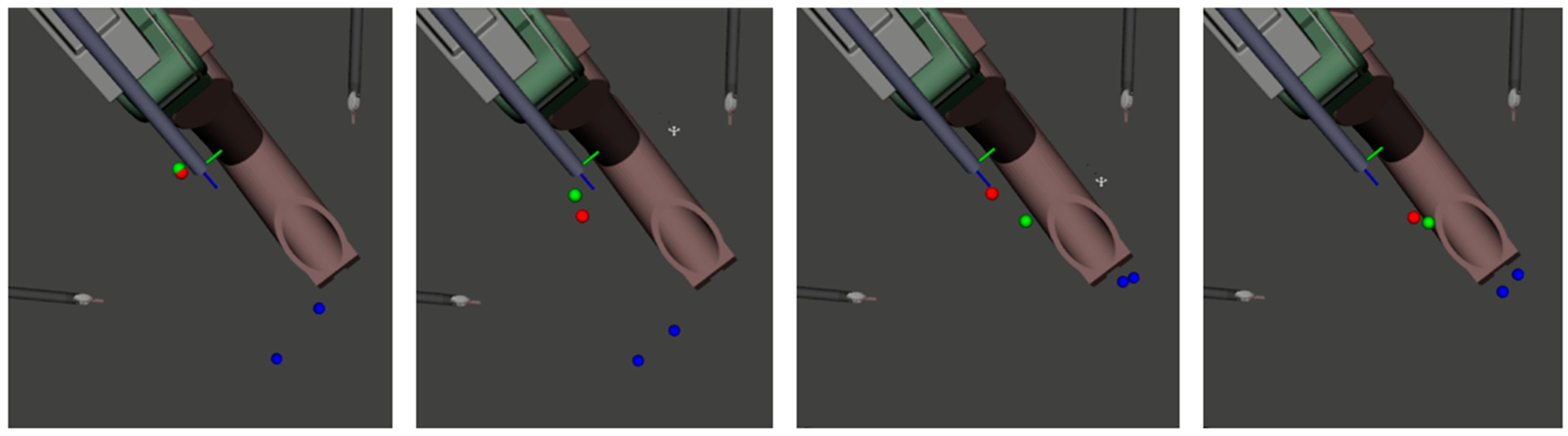
Figure 10.
Visualization of the GRU predicted ECM position (green), the dataset-given ECM position (red), and the dataset-given PSM positions (blue) over time. Note that the actual ECM/PSMs are only shown for context to allow an uninterrupted view of the predicted/dataset positions.
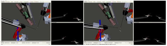
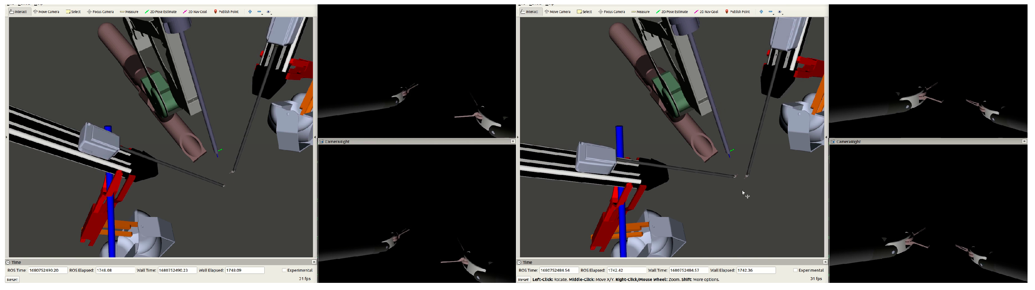
Figure 11.
Two stills from the GRU-controlled ECM at different points along pre-recorded and played-back PSM motions. The left pane of each still shows the relative positions of the ECM and the PSMs, while the top and bottom panes on the right are the images from the left and right cameras of the ECM, respectively.
4.3. Neural Network and ROS Latency
In time-sensitive applications such as surgery, latency must be minimized. As a result, evaluating the latency in our system was vitally important. The average latency of the developed neural networks was measured with and without the ROS system developed in this paper. The latency of the entire dVRK ROS network was not considered. The networks and system were tested on a machine with an Intel i7 2.60 GHz CPU, 16 GB DRAM, and an NVIDIA GTX 1060 with 6 GB VRAM.
The results in Table 2 show a base prediction time of 2 ms for the dense network and 33 ms for the GRU network after it fills the buffer of 50 timesteps. When considering the networks with the ROS service calls, the dense network had a prediction time of 13 ms, compared to the GRU’s 45 ms. This indicates that the latency added using ROS is, on average, 11.5 ms.
Table 2.
Measured average deep neural network prediction times with and without the ROS network. The ROS time refers to the time it takes for the camera control class to make the service request and send the data + the time it takes for the neural network to make its prediction + the time it takes for the service response to get back to the camera control class.
5. Discussion
The results demonstrate that both the dense and recurrent network were able to learn to appropriately position the ECM based on the positions of the PSMs. The dense network is predictably fast with an inference speed of 2 ms and showed good accuracy in providing an appropriate camera position on two of the three axes (X and Y) but was unable to learn the zoom level—associated with the Z-axis of the camera—due to the temporal nature of that algorithm. This resulted in either the camera being too zoomed in or out, thereby losing some valuable information. On the other hand, the GRU was able to learn the position and zoom level and achieved sub-millimeter accuracy when compared to the dataset-given values. This can be attributed to the nature of the GRU cell, which allows it to take the temporal aspect of the zoom into consideration. The GRU-based network is slower in inference with an average inference time of 33 ms owing to the much more complex architecture, but it may still be fast enough for surgical camera applications.
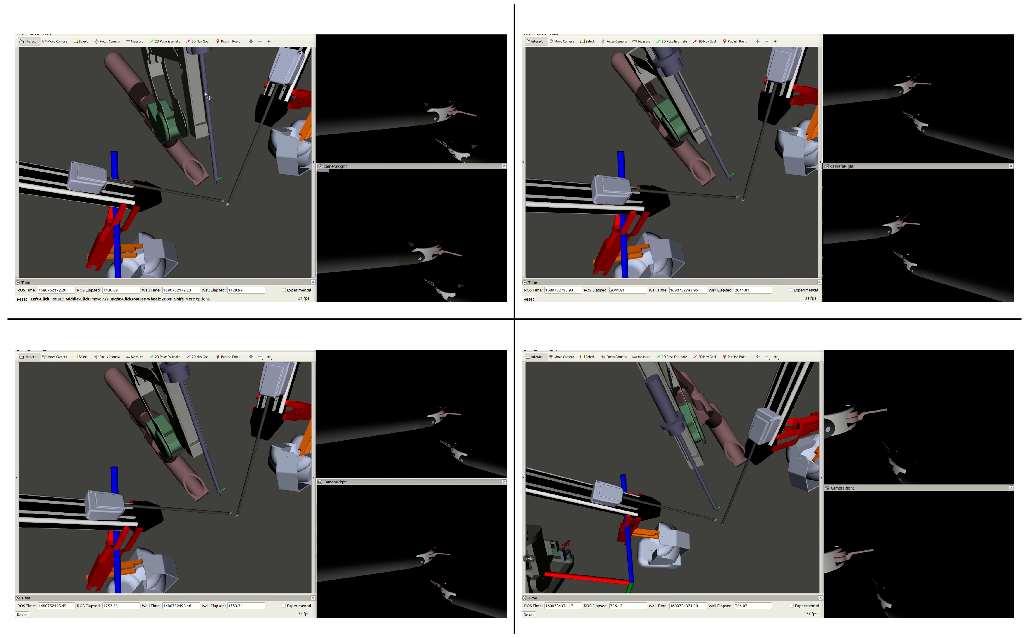
The deep-learning-based approach developed in this paper is able to imitate the best of both worlds by learning the appropriate camera position based on data from a human-controlled ECM and an autonomous system. Figure 12 shows the difference in the camera position and view when controlled by the neural networks, joystick, and autonomous camera control methods. All methods were given the same set of PSM motions and videos showing the performance of each can be found in the supplementary materials. As seen in the figure, the joystick operator sometimes allows the tools to go out of the field-of-view leading to unsafe conditions, but otherwise it retains a good view of the scene and tools. As previously stated, the autocamera is bound by a rigid set of rules, as evidenced by it keeping the PSMs directly in the center of the camera view and having them be the sole focus. In comparison, the dense network keeps the tools in view, but fares a little worse than the autocamera algorithm regarding the zoom level due to the reasons stated above and may occasionally lose sight of the PSMs due to attempting to keep the rest of the scene in view. The GRU network maintains a good view of the tools and the surrounding scene, and, while the viewpoint given by the GRU-controlled network does not always have the tools centered in the view, it does nonetheless always retain a view of them. The snapshots provided in Figure 6, Figure 7, Figure 10, Figure 11 and Figure 12 represent broader trends seen in all the camera control methods. Ultimately, the networks—the GRU in particular—have demonstrated the capability to learn safe camera positioning from the autonomous system and perhaps (due to its memory units) better predictive movement timing from the human joystick–operator. However, it is inherently difficult to formalize the behavior of humans, especially in this situation where they may have been reacting to visual stimuli in the camera view. This being the case, the behavior considered to have transferred over to the networks is the enhanced predictive timing of the joystick operator in the study. It is, however, believed that the networks learned other human behaviors that cannot be explicitly formalized in a systematic way. This lack of explainability in neural networks is a topic of much contention and research, especially where it relates to the field of medicine [17,18,19,20]. Overall, the ability of neural networks to accurately learn camera positioning is perhaps not that surprising given that neural networks have been shown to be excellent linear- and nonlinear-function approximators given the right network configuration [21,22].
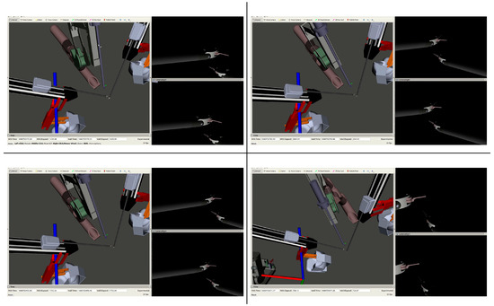
Figure 12.
Stills captured from each camera control method: Dense (top left), GRU (bottom left), autocamera (top right), and joystick (bottom right). Each shows the relative positions of the PSMs and ECM, as well as the views from both the left and right lenses of the ECM camera.
6. Conclusions and Future Work
In conclusion, this study effectively demonstrates the distinct learning capabilities of dense neural networks and gated recurrent units in the context of teleoperated robotic camera control. Both networks successfully learned to position the endoscopic camera manipulator based on the positions of the patient side manipulators from data gathered from an automated algorithm and human operated data. While the DNN showed proficiency in basic tool tracking, it struggled with the camera’s zoom functionality due to its inherent architectural constraints. In contrast, the GRU not only replicated these behaviors but also excelled in learning the task of timing-based camera zooming, a function crucial for optimal surgical views. The integration of human joystick-operated data added a layer of complexity to the learning process, potentially enhancing the GRU’s ability to predict and time camera movements more effectively. This suggests that the GRU could assimilate some aspects of human behavioral patterns, although the exact nature of this learning remains challenging to formalize systematically. This research underscores the potential of neural networks in enhancing the efficiency and adaptability of robotic surgical systems, marrying autonomous precision with nuanced human-like control.
For future work, a more comprehensive collection and analysis of complex human camera movements in surgical contexts is essential. This endeavor should focus on obtaining a larger, more diverse dataset that captures a wide range of human-operated camera control behaviors during various surgical procedures. Such data will offer invaluable insights into the nuances of human control, particularly in complex and dynamic surgical environments. With this new approach, it may be possible to understand and quantify the intricate decision-making processes and contextual adjustments made by human operators and capture this using advanced neural network models. Along with more thorough training on a wider variety of surgical tasks, the camera controller can be integrated as part of an on-demand system. In this system, the surgeon can toggle the autonomous system and take manual control at will, therefore, retaining a level of control over the endoscopic camera.
Subsequently, a rigorous human factors assessment is necessary, where neural network-based camera control methods, including both current and advanced models (deep inverse reinforcement learning, convolutional NN), should be systematically compared against traditional human-operated methods. This evaluation should aim to measure not only the accuracy and efficiency of camera positioning but also factors like ease of use, the cognitive load on the surgeon, and its overall integration within the surgical workflow. By doing so, the study can illuminate the practical implications of implementing NN-based camera control in real-world surgical settings and guide the development of more intuitive, responsive, and context-aware artificial intelligence systems in robotic surgery.
Supplementary Materials
The following supporting information can be downloaded at https://www.mdpi.com/article/10.3390/robotics13030047/s1.
Author Contributions
Conceptualization, L.J. and A.P.; methodology, L.J. and A.P.; software, L.J. and A.S.-C.; validation, L.J. and A.S.-C.; formal analysis, L.J. and A.S.-C.; investigation, L.J., A.S.-C., A.S. and A.P.; resources, A.P.; data curation, L.J. and A.P.; writing—original draft preparation, L.J., A.S.-C., A.S. and A.P.; writing—review and editing, L.J., A.S.-C., A.S. and A.P.; visualization, L.J. and A.S.-C.; supervision, A.P.; project administration, L.J. and A.P.; funding acquisition, A.P. All authors have read and agreed to the published version of the manuscript.
Funding
This research received no external funding.
Institutional Review Board Statement
The data was reused from our previous paper (Eslamian et al., Development and evaluation of an autonomous camera control algorithm on the da Vinci Surgical System, https://doi.org/10.1002/rcs.2036 (accessed on 23 September 2023)), which was conducted in accordance with the Declaration of Helsinki. And, the protocol was approved by the Ethics Committee of Wayne State University’s Institutional Review Board (IRB) with IRB No. 082105B3E(R).
Data Availability Statement
Datasets available on request from the authors.
Conflicts of Interest
The authors declare no conflicts of interest.
Appendix A

Figure A1.
GRU network architecture with activations.
Figure A1.
GRU network architecture with activations.
References
- Eslamian, S.; Reisner, L.A.; Pandya, A.K. Development and evaluation of an autonomous camera control algorithm on the da Vinci Surgical System. Int. J. Med. Robot. Comput. Assist. Surg. 2020, 16, e2036. [Google Scholar] [CrossRef] [PubMed]
- Pandya, A.; Reisner, L.A.; King, B.; Lucas, N.; Composto, A.; Klein, M.; Ellis, R.D. A review of camera viewpoint automation in robotic and laparoscopic surgery. Robotics 2014, 3, 310–329. [Google Scholar] [CrossRef]
- Da Col, T.; Mariani, A.; Deguet, A.; Menciassi, A.; Kazanzides, P.; De Momi, E. Scan: System for camera autonomous navigation in robotic-assisted surgery. In Proceedings of the 2020 IEEE/RSJ International Conference on Intelligent Robots and Systems (IROS), Las Vegas, NV, USA, 24 October 2020–24 January 2021; pp. 2996–3002. [Google Scholar]
- Garcia-Peraza-Herrera, L.C.; Gruijthuijsen, C.; Borghesan, G.; Reynaerts, D.; Deprest, J.; Ourselin, S.; Vercauteren, T.; Vander Poorten, E. Robotic Endoscope Control via Autonomous Instrument Tracking. Front. Robot. AI 2022, 9, 832208. [Google Scholar]
- Elazzazi, M.; Jawad, L.; Hilfi, M.; Pandya, A. A Natural Language Interface for an Autonomous Camera Control System on the da Vinci Surgical Robot. Robotics 2022, 11, 40. [Google Scholar] [CrossRef]
- Kossowsky, H.; Nisky, I. Predicting the timing of camera movements from the kinematics of instruments in robotic-assisted surgery using artificial neural networks. IEEE Trans. Med. Robot. Bionics 2022, 4, 391–402. [Google Scholar] [CrossRef]
- Sarikaya, D.; Corso, J.J.; Guru, K.A. Detection and localization of robotic tools in robot-assisted surgery videos using deep neural networks for region proposal and detection. IEEE Trans. Med. Imaging 2017, 36, 1542–1549. [Google Scholar] [CrossRef]
- Lu, J.; Jayakumari, A.; Richter, F.; Li, Y.; Yip, M.C. Super deep: A surgical perception framework for robotic tissue manipulation using deep learning for feature extraction. In Proceedings of the 2021 IEEE International Conference on Robotics and Automation (ICRA), Xi’an, China, 30 May–5 June 2021; pp. 4783–4789. [Google Scholar]
- Azqueta-Gavaldon, I.; Fröhlich, F.; Strobl, K.; Triebel, R. Segmentation of surgical instruments for minimally-invasive robot-assisted procedures using generative deep neural networks. arXiv 2020, arXiv:2006.03486. [Google Scholar]
- Wagner, M.; Bihlmaier, A.; Kenngott, H.G.; Mietkowski, P.; Scheikl, P.M.; Bodenstedt, S.; Schiepe-Tiska, A.; Vetter, J.; Nickel, F.; Speidel, S. A learning robot for cognitive camera control in minimally invasive surgery. Surg. Endosc. 2021, 35, 5365–5374. [Google Scholar] [CrossRef] [PubMed]
- Li, B.; Lu, Y.; Chen, W.; Lu, B.; Zhong, F.; Dou, Q.; Liu, Y.-H. GMM-based Heuristic Decision Framework for Safe Automated Laparoscope Control. IEEE Robot. Autom. Lett. 2024, 9, 1969–1976. [Google Scholar] [CrossRef]
- Liu, Z.; Zhou, Y.; Zheng, L.; Zhang, G. SINet: A hybrid deep CNN model for real-time detection and segmentation of surgical instruments. Biomed. Signal Process. Control. 2024, 88, 105670. [Google Scholar] [CrossRef]
- Available online: https://keras.io (accessed on 23 September 2023).
- Kazanzides, P.; Chen, Z.; Deguet, A.; Fischer, G.S.; Taylor, R.H.; DiMaio, S.P. An open-source research kit for the da Vinci® Surgical System. In Proceedings of the 2014 IEEE International Conference on Robotics and Automation (ICRA), Hong Kong, China, 31 May–7 June 2014; pp. 6434–6439. [Google Scholar]
- Cho, K.; Van Merriënboer, B.; Gulcehre, C.; Bahdanau, D.; Bougares, F.; Schwenk, H.; Bengio, Y. Learning phrase representations using RNN encoder-decoder for statistical machine translation. arXiv 2014, arXiv:1406.1078. [Google Scholar]
- Chung, J.; Gulcehre, C.; Cho, K.; Bengio, Y. Empirical evaluation of gated recurrent neural networks on sequence modeling. arXiv 2014, arXiv:1412.3555. [Google Scholar]
- Xu, F.; Uszkoreit, H.; Du, Y.; Fan, W.; Zhao, D.; Zhu, J. Explainable AI: A brief survey on history, research areas, approaches and challenges. In Proceedings of the Natural Language Processing and Chinese Computing: 8th CCF International Conference, NLPCC 2019, Dunhuang, China, 9–14 October 2019; pp. 563–574. [Google Scholar]
- Samek, W.; Wiegand, T.; Müller, K.-R. Explainable artificial intelligence: Understanding, visualizing and interpreting deep learning models. arXiv 2017, arXiv:1708.08296. [Google Scholar]
- Yu, L.; Xiang, W.; Fang, J.; Chen, Y.-P.P.; Zhu, R. A novel explainable neural network for Alzheimer’s disease diagnosis. Pattern Recognit. 2022, 131, 108876. [Google Scholar] [CrossRef]
- Hughes, J.W.; Olgin, J.E.; Avram, R.; Abreau, S.A.; Sittler, T.; Radia, K.; Hsia, H.; Walters, T.; Lee, B.; Gonzalez, J.E. Performance of a convolutional neural network and explainability technique for 12-lead electrocardiogram interpretation. JAMA Cardiol. 2021, 6, 1285–1295. [Google Scholar] [CrossRef]
- Hassoun, M.H. Fundamentals of Artificial Neural Networks; MIT Press: Cambridge, MA, USA, 1995. [Google Scholar]
- Hornik, K. Approximation capabilities of multilayer feedforward networks. Neural Netw. 1991, 4, 251–257. [Google Scholar] [CrossRef]


Disclaimer/Publisher’s Note: The statements, opinions and data contained in all publications are solely those of the individual author(s) and contributor(s) and not of MDPI and/or the editor(s). MDPI and/or the editor(s) disclaim responsibility for any injury to people or property resulting from any ideas, methods, instructions or products referred to in the content. |
© 2024 by the authors. Licensee MDPI, Basel, Switzerland. This article is an open access article distributed under the terms and conditions of the Creative Commons Attribution (CC BY) license (https://creativecommons.org/licenses/by/4.0/).