Article

A Reconfigurable UGV for Modular and Flexible Inspection Tasks in Nuclear Sites

by
Ivan Villaverde
*,†,
Arkaitz Urquiza
and
Jose Luis Outón
TECNALIA, Basque Research and Technology Alliance (BRTA), Mikeletegi Pasealekua 7, 20009 Donostia-San Sebastián, Gipuzkoa, Spain
*
Author to whom correspondence should be addressed.
These authors contributed equally to this work.
Robotics 2024, 13(7), 110; https://doi.org/10.3390/robotics13070110
Submission received: 12 June 2024 / Revised: 5 July 2024 / Accepted: 15 July 2024 / Published: 22 July 2024
(This article belongs to the Section Aerospace Robotics and Autonomous Systems)

Abstract

:
Current operations involving Dismantling and Decommissioning (D&D) in nuclear and other harsh environments rely on manual inspection and assessment of the sites, exposing human operators to potentially dangerous situations. This work presents a reconfigurable Autonomous Mobile Robot (AMR) able to mount a wide range of nuclear sensors for flexible and modular inspection tasks in these operations. This AMR is part of the CLEANDEM solution, which uses Unmanned Ground Vehicles (UGVs), nuclear sensors, and a Digital Twin to facilitate a tool for improving D&D operations in nuclear sites. Both the AMR used as a UGV and the system have been successfully tested in real nuclear sites, showing that these tools can greatly aid in operations management and hazard reduction.

1. Introduction

One of the main motives driving the introduction of robotics in various applications is to increase the safety of human operators while reducing the labor risks that they face [1].
The nuclear sector is one paradigmatic example of a hazardous environment. In addition to the risk of exposure to ionizing radiation or accidents, nuclear workers face a variety of hazards ranging from chemical and mechanical (high temperatures, high noises, low ergonomics) to the psychological stresses related to working in a high-risk and high-security environment [2]. Regardless of their potential applicability, robots face various challenges in such environments, including restricted accessibility, lack of reliable communications, cluttered spaces, potential radiation, reliability, autonomous decision-making, and more [3]. Thus far, these challenges have prevented the widespread use [4] that has happened in other sectors such as manufacturing and logistics.
However, from very early on, the use of robots in nuclear environments and sites has been explored. Perhaps the most famous examples are related to accidents, such as Three Mile Island, Chernobyl, and Fukushima, where robots were used to clean up, collect samples, and evaluate the situation [5].
Beyond this, both Autonomous Mobile Robots (AMRs) and robotic manipulators are currently being evaluated for use in other situations related to the daily operation or decommissioning of nuclear facilities, including waste manipulation [6], sampling, monitoring, and inspection, with most research focused on mobile manipulators [7,8]. The research focus is usually placed on facing the challenges mentioned above, exploring advanced sensing and map-making approaches [9], autonomous navigation [10] and path-planning [11,12], drone swarms [13], HMIs, and teleoperation [14].
In the specific case of Dismantling and Decommissioning (D&D) operations, one of the key tasks is radiological assessment of the site. This task must be performed continuously during the operations, from the initial to the final characterization, with multiple intermediate inspection rounds to assess the effect of the cleaning actions carried out. This operation, especially the initial characterization, is one of the situations where operators are at high risk of facing the previously mentioned hazards [2]. In [15], the authors provide an extensive review of the robots used for nuclear site characterization over the last 50 years. The review shows that while many applications have been developed, the particular solutions are usually tailored to the specific geometries of the operation site. Recent approaches use land robots with specific sets of sensors [16], focusing more on the processing of data. Alternatively, they may use different robots for different tasks and sensors, such as Unmanned Ground Vehicles (UGVs) and Unmanned Aircraft Systems (UAS) [17]. Currently, there is a trend towards using small, low-cost, and quasi-disposable robots [8,18].
In this context, the present work presents some of the results of the CLEANDEM project [19] (funded by the EU’s Horizon 2020 Euratom Nuclear Fission and Radiation Protection Research call) [20], where a UGV is used for radiation monitoring and nuclear site characterization. Rooted in the lessons learned during the development of the previous RIANA robot [8], this UGV is used as a low-cost deployment vector for a varied range of nuclear sensors in different configurations that is able to operate in as many operational environments as possible.
In this paper, we briefly introduce the CLEANDEM project (described in [19]). The proposed system and the elements composing it are described in Section 2. The AMR used as a UGV is described in Section 2.2. In Section 3, we describe the integration of the different sensors in the UGV and the several configurations available. In the following Section 4, we present the testing iterations and real-life demonstrators carried out at actual nuclear facilities during the development of the project. In the final Section 5, we discuss the challenges overcome, mainly related to environmental and integration issues, along with the results and future work.

2. System Description

2.1. Application

The goal application of the CLEANDEM project is to assist the operations and reduce risks to human operators during D&D at nuclear sites. This application comes in the form of an SW/HW platform that eases radiological assessment of the environment, providing a comprehensive tool for continuous monitoring. Currently, D&D operations require intensive human intervention. These human operators can be exposed to harsh and potentially dangerous environments, especially during the initial assessment. Automation of the initial phase and further monitoring tasks can significantly reduce human operators’ exposure to these harsh environments. In addition, the Digital Twin (DT)-driven fully 3D representation monitoring tool helps in tracking the situation and planning activities.
The platform is composed of three pillars [19]: a range of sensors that provide radiological measurements, a DT to display the measurements, and a UGV to deploy the sensors in the site to be monitored. One of the key elements of the platform is its modularity and reconfigurability, allowing for greater flexibility in the planning of the operations. The wide range of sensors and the multiple UGV–sensor configurations provide extensive monitoring capabilities that can adapt to a great variety of use cases.
In this work, we focus on the AMR used as a UGV (as we refer to it further on); thus, we provide only a brief description of the other systems composing the CLEANDEM platform.

2.2. UGV

The UGV is the central pillar of the system, responsible for deploying the sensors inside the space to be monitored. Based on the initial assessment of the requirements as well as our previous experience in the development of industrial mobile manipulators [21,22] and the nuclear inspection robot RIANA [8], its development followed several criteria:
  • Use off-the-shelf components: Previous experience with the RIANA robot showed that the engineering requirements for customizing a robot for the nuclear environment represent a major driver of costs and delivery times. Because the main objective in this project was the integration of multiple sensors, the UGV, and the DT into a single platform, hardware adaptations to the nuclear environment (e.g., air filtering, avoiding certain materials, shapes minimizing contamination risk, etc.) were not deemed a requirement. Thus, the base platform should be a single commercial platform that fulfills the functional requirements as closely as possible while requiring only minor modifications, such as adding new sensors or providing additional power supplies and connectivity.
  • Indoor–outdoor operation: Due to the wide variety of potential environments for application, the UGV should be able to operate both outdoors and indoors as well as in GPS-denied environments.
  • Rough terrain operation: At least one of the potential use cases implies navigation in outdoor, unpaved, and uneven terrain. In indoor environments, the platform may need to overcome small obstacles or trenches. Thus, it should be able to operate in rough terrain and should ideally possess off-road capabilities.
  • Autonomous and teleoperated: The UGV should have the capacity for either manually teleoperated (first-time exploration, manual control on difficult-to-reach spots, etc.) or fully autonomous operation (routine inspections, exploration beyond communications range, etc.).
  • Modular configuration: The UGV must mount a variety of sensors in different configurations. Thus, it should be able to engage in:
    -
    Arm and arm-less operation: Certain sensors are required to be mounted on a robotic arm to ensure that they can be placed close to the radioactive source. However, the arm takes up a lot of space, which could hinder the available space for other sensor configurations. Thus, the arm should be easily detachable, and the robot be able to operate both with and without the arm without requiring complex configuration changes.
    -
    Electrical and communication interfaces: The UGV should provide sufficient varied interfaces for different sensors, including their mounting, power, and communications.
    -
    Help with data management: The UGV should be able to relay all the sensor data to the DT, allow sensors to be managed remotely, retain data in case of communications fault, and ensure that all of the sensors are synchronized.

2.2.1. Platform

Considering the previous requirements, a market survey of available commercial AMRs and robotic arms was carried out. The selected platform was the RB-VOGUI robot [23] from the Spanish manufacturer Robotnik Automation. This platform matched most of the requirements while falling into the available budget, and has full ROS (Robot Operating System) [24] support. The robot uses a swerve drive to achieve omnidirectional movement. It is equipped with four rubber wheels with independent steering and drive on an elevated chassis, allowing it to drive both indoors and outdoors on rough, uneven, and unpaved floors. Its wheel size and height also allow it to overcome small obstacles and trenches, and even to climb small steps. It is big enough to accommodate several sensors and their electronics boxes at a time while still being small enough to fit through doors and into elevators.
Over this base platform, several customizations were made to fit the requirements:
  • Additional sensor suite: 2D LiDAR, 3D LiDAR, GPS, and IMU.
  • Flexible 3D LiDAR mounting, allowing elevation or tilting of the 3D LiDAR to cope with the occlusions caused by the different elements that could be mounted (arm, sensor electronics boxes).
  • Additional wireless communications hardware.
  • Additional DC power supplies for 5, 12, 24, and 48 V and PoE, with external IP54 connection ports.
  • Additional external RJ-45 and USB ports with IP54 protection.
  • Top mounting plate with threaded holes for easy module installation.
  • Removed some holes and structural elements prone to accumulating dust.
  • Removable anchor points for lifting.
For the robotic arm, an UR-5e [25] from Universal Robots was chosen, as their compact controller allowed for embedded installation on the RB-VOGUI platform and the arm was big enough to reach the floor from the mounting plate. The modularity of the ROS allows the arm to be an optional component of the system, making it possible to run with or without the arm being present. In addition, following standard safety procedures for arm mounting, the absence of the arm when operating in armless mode should trigger a safety signal. To avoid this, a mechanism for easily bypassing the arm’s safety signal was installed.

2.2.2. Autonomous Capabilities

One of the aims of the CLEANDEM solution is to achieve a substantial advancement from previous developments in terms of environmental perception, location accuracy, and accurate navigation.
The default navigation provided by the UGV manufacturer used the standard 2D navigation stack from ROS. We used a similar approach in our previous experience with the RIANA robot [8] and concluded that the performance of 2D laser-based navigation was not adequate in this kind of environment and for the application requirements, especially regarding positioning accuracy and robustness. Thus, the localization solution adopted should enhance measurement accuracy and repeatability in environments where traditional 2D localization is insufficient, such as outdoor areas and tight, cluttered, or corridor-based indoor environments.
The approach that we followed was to shift from 2D to 3D localization/navigation. Three-dimensional environments provide richer information, enabling better accuracy with quickly generated maps and improved localization in both vast, featureless outdoor settings and tight and repetitive indoor ones; however, although many modules cover different aspects of 3D Navigation in ROS, there is currently no standard 3D navigation suite available that covers all of them in a single solution. Thus, the autonomous navigation solution that we adopted was to create a 3D navigation suite by combining various freely available modules and integrating them with the standard ROS navigation stack.
The compiled suite follows a 2.5D navigation approach; mapping and localization are performed in full 3D with six degrees of freedom, while path planning takes place over a 2D transitability map extracted from the 3D map. This suite is composed of three main software modules:
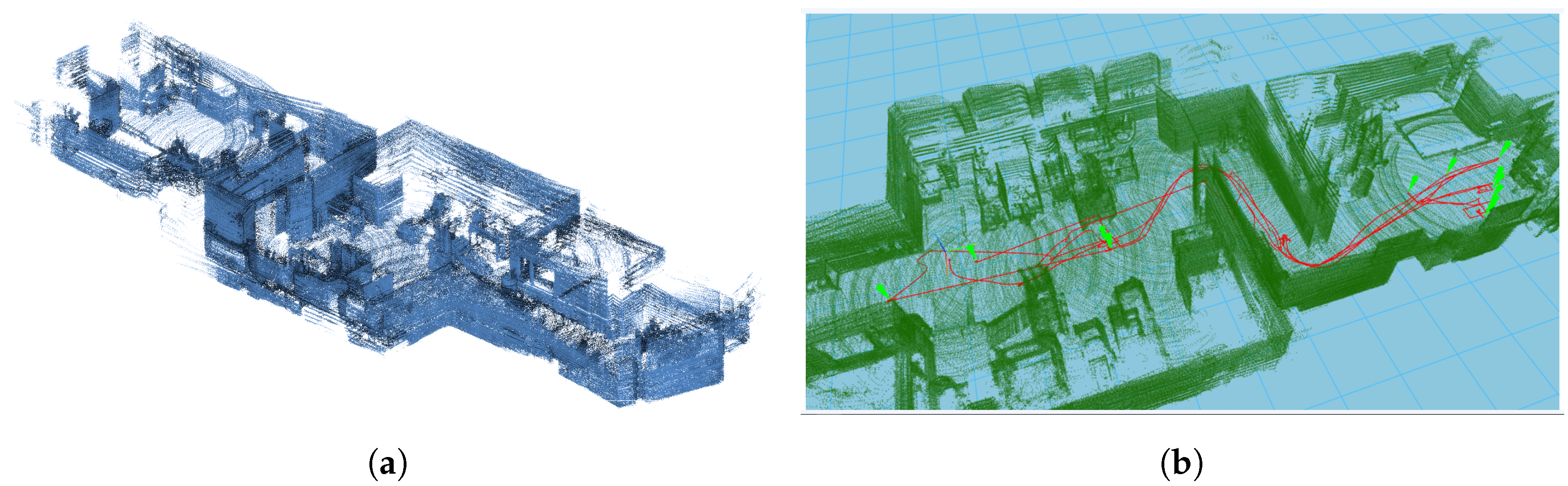
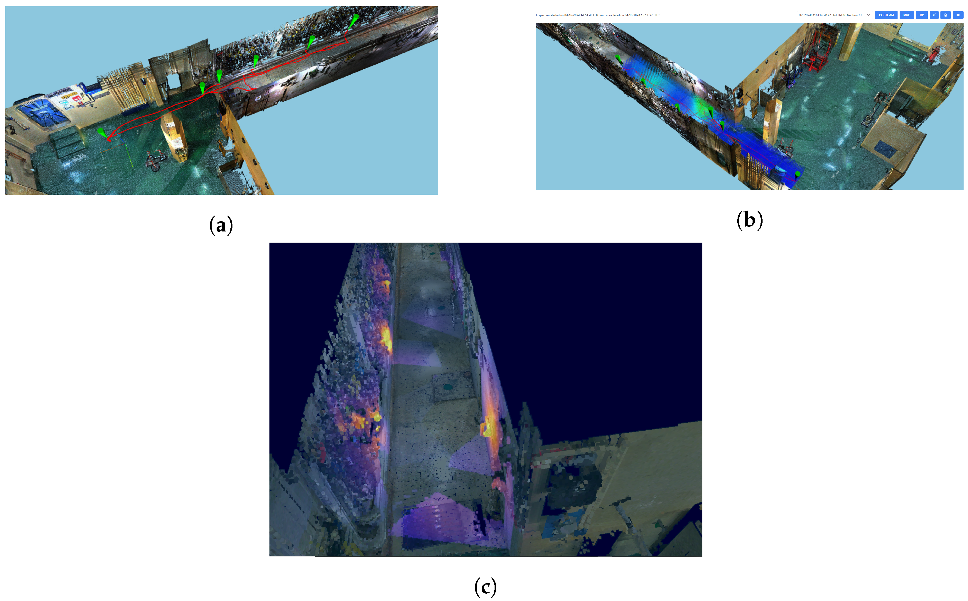
  • A mapping module that uses LIO-SAM [26] to generate a 3D map. LIO-SAM is an odometry generation library based on LiDAR and IMU sensors. Sensor movement is accurately estimated by combining point cloud matching with inertial measurement. The point clouds are de-skewed using the IMU information to account for displacement during the cloud acquisition, and point cloud matching is performed against a 3D representation created from invariant points detected in the point clouds. This 3D representation is dense enough to be used as a 3D map (example shown in Figure 1a) for later navigation.
  • A localization module that uses HDL_localization [27] for point cloud matching against a global map. The localization performed by this library is based on a variant of the Normal Distribution Transform (NDT) [28]. The system keeps track of the estimated position using an Unscented Kalman Filter. Each step the estimated pose is updated using inertial measurement and then refined using the aforementioned NDT method.
  • A planning module that creates a 2.5D representation of the environment from the 3D map, using it to plan the robot’s trajectories using standard 2D planning algorithms. The 2.5D representation tries to extract the floor from the 3D map as an elevation surface (Figure 1b) using the ROS grid_map [29] module. From this surface, a “transitability” map is computed (Figure 1c) as a function of the slope and roughness of the terrain around each map cell. This transitability map represents the parts of the floor that are considered reachable by robot. The path planning itself is accomplished using the ROS standard navigation stack using global_planner [30] and TEB planner [31] over the transitability map stored as a 2D cost map.
Due to the constraints of the demonstration sites, thus far the system has only been tested in real-life conditions in indoor environments, with some successful tests made on prerecorded outdoor data. Integration with GPS for higher accuracy in low-feature outdoor environments is still pending.

2.3. Sensors

The platform’s array of sensors is composed of eight different sensors developed by four of the project’s partners (CAEN, CEA, ENEA, and INFN). The first six of the sensors listed here would be mounted on the described UGV, while the other two are either too large or too complex to deploy mounted onboard a mobile platform.
  • CTZ compact sensor for γ source hotspot detection (CAEN). This sensor needs to be pointed at the source, as its shielding makes the detection ability directional.
  • Nanopix3 imager for visual and directional identification of γ sources (CEA). The Nanopix3 must be pointed like a normal camera to identify γ sources in the image.
  • GAMON-DRONE and SNIPER-GN 2.0 for neutron and γ source detection and identification (CAEN). These are spot sensors, sensing in all directions; they must be kept at a certain distance from the UGV to avoid occlusions.
  • MiniRadMeter and MiniSiLiF low-cost sensors for γ and neutron source detection and identification (INFN) [32]. These are also spot sensors, meaning that occlusions should be avoided.
  • PSD phoswitch α / β detector for large-surface contamination measurement (CAEN). It must be placed close to the surface to be measured and moved in parallel from it to ensure full surface coverage.
  • Surface pixelated β / γ detector based on plastic scintillators for large-surface contamination measurement (CEA), with similar requirements to the previous sensor.
  • Cryogenic system for air contamination monitoring and 14CO2 detection (ENEA). This is a very large and heavy system unsuitable for embarked UGV operation.
  • OSL/FO dosimetry and shape-sensing for monitoring of large structures (CEA). A long and flexible sensor with a very complex deployment procedure, operation of this sensor by a single robotic arm is impracticable.

2.4. Data Fusion and Digital Twin

To ease site monitoring, all of the data gathered by the different sensors must be compiled, processed, and presented to the user in an effective, interactive, and visually comprehensive way.
In the CLEANDEM project, this is achieved through a Digital Twin developed by the partner RINA-CSM using their proprietary QPro² system [33]. This web-based interface shows all the data gathered by the different sensors overlaid on a 3D reconstruction of the environment. The DT also integrates with ORANO’s PoStLAM [34], which processes the sensors’ measurements in 3D to generate a radiological map that can then be over-imposed in the 3D reconstruction of the environment.

3. Sensor Integration and Configurations

For the integration of each sensor in the UGV, three elements have been considered: mounting, power, and data gathering and management.

3.1. Mounting

The sensors can have special requirements for mounting, such as maximizing the distance from the UGV to avoid shielding or being deployed close to the radiological source. Three options were considered for mounting:
  • Mounted directly over the UGV plate: This was the case for most of the electronic boxes accompanying the sensors. The MiniRadMeter and MiniSiLiF sensors could also be mounted directly over the plate, though with reduced sensitivity.
  • Mounted on the robot arm’s flange: This was used for sensors that need to be close to the source (CTZ sensor), sensors that measure surfaces (PSD and Pixelated detectors), and sensors that need to be pointed at a source (NanoPix3). Customized tooling for mounting the different sensors was designed and manufactured by the partner Ansaldo Nucleare.
  • Mounted on top of a pole: GAMON-DRONE, SNIPER-GN, MiniRadMeter, and MiniSiLiF are ambient sensors, and as such need to be separated as much as possible from the UGV to avoid the shielding it provides. These sensors were mounted on top of a 50 cm pole.
Given the different mounting requirements and space required for sensor electronic boxes, several viable mission configurations had to be defined. The main limitations for valid configurations come from the need to mount the robotic arm and the size of the different electronic boxes coming with each sensor. Currently, four different sensor configurations for the UGV have been tested. The PSD phoswitch and the pixelated detector need to be arm-mounted; combined with their big electronic boxes, this does not leave very much available space for any equipment other than the MiniRadMeter and MiniSiLiF. Thanks to this module’s compact size, it was possible to mount it on the plate just under the arm’s second joint. While this position is suboptimal due to the shielding caused by proximity to the UGV, it allows for both ambient radiation sensing and surface contamination measurements. While the Nanopix3 and CTZ sensor were small enough to be mounted together on the arm’s flange, their electronics boxes prevented mounting other elements beyond the MiniRadMeter and MiniSiLiF. Finally, the GAMON-DRONE, SNIPER-GN, MiniRadMeter, and MiniSiLiF could be mounted together optimally on top of a pole that prevented shielding from the UGV. Table 1 summarizes the tested configurations, including their data and power connectivity, which are discussed further below. Figure 2 shows images of the designed and final sensor configurations mounted on the real UGV.

3.2. Power

The different sensors had different power requirements; as stated before, several power supply options were made available in the UGV using standard interfaces. However, many of the sensors were developed as portable equipment, and as such were powered using internal batteries. Among the tested sensors, only the Nanopix3 made use of the PoE, while only the MiniRadMeter and MiniSiLif made use of the 24 V power supply.

3.3. Data Connectivity and Management

Three connectivity types were made available for the sensors in the UGV:
  • An access point inside the UGV provided a local WiFi connection. This connectivity was used by the CTZ, PSD, Pixelated, GAMON-DRONE, and SNIPER-GN sensors.
  • Several RJ-45 external connectors, including PoE, were available to connect sensors to the UGV’s internal network. The Nanopix3 and the MiniRadMeter and MiniSiLiF used this power connection.
  • Several USB 2.0 and 3.0 external connectors were also available. While the Nanopix3 and CTZ could use these for power, they were not used in the tested configurations.
The final functionality that the UGV had to provide was to help with data management and gathering for the DT. For this data management task, three aspects were undertaken:
  • Clock synchronization: Because the UGV is expected to move around the environment, all sensor measurements must be accurately timed to ensure proper data visualization. As the UGV is the central element, an NTP server was set up to allow all the sensors to synchronize their clocks with the UGV’s time.
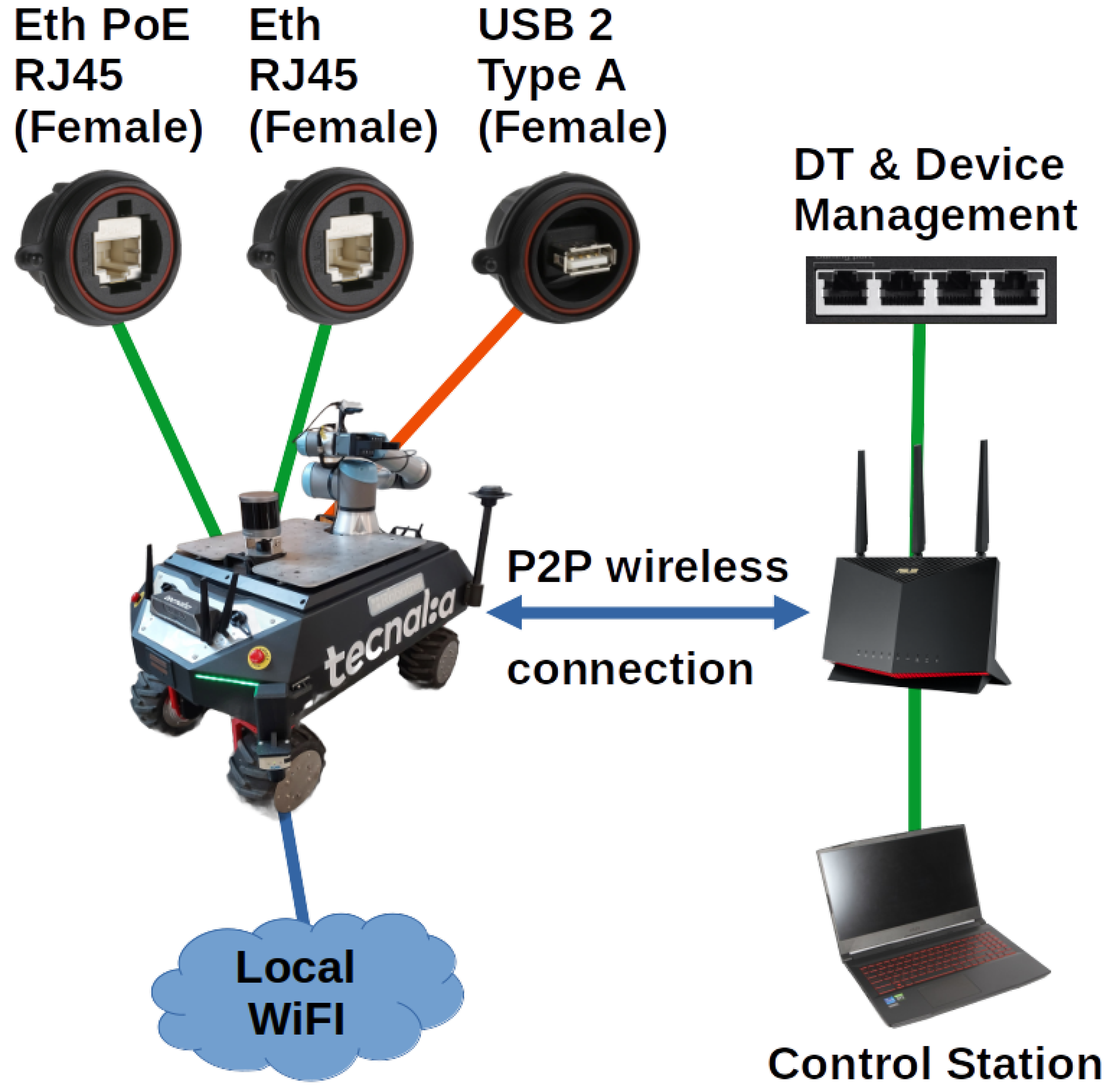
  • Remote data gathering and sensor management: The sensors mounted on the UGV have local access to its internal network through Ethernet or WiFi. This local WiFi has a low range and bandwidth, making it unsuitable for remote sensor management, especially if it must share bandwidth with the teleoperation connection. Thus, a UGV control station architecture was built, as shown in Figure 3. Sensors connect to the UGV by the available means, while the DT and the sensors’ remote management equipment connect to a control station using Ethernet. The connection between the UGV and the control station is provided by a dedicated high-bandwidth P2P wireless connection using WiFi 6.
  • Local data storage: All the sensor measurements are stored in text format logs, as are the poses of the UGV and the arm. The UGV provides local storage for these logs using Samba and FTP shares. The logs can be retrieved by the DT after the mission, guaranteeing that data are registered even if communication with the UGV is lost.

4. Testing and Demonstrator

In addition to the individual and iterative testing carried out on each of the system components during the development of the project, three rounds of system tests were performed. These aimed to assess the integration of the different elements and to test the system as a whole while assessing any deployment challenges and demonstrating its capabilities. An initial integration test was carried out in early 2023 at TECNALIA’s premises in Donostia-San Sebastián, Spain. A second full integration test with nuclear sources was carried out in early 2024 at a nuclear research site on the AiNT premises in Aachen, Germany. Finally, a final demonstration was performed in April 2024 in a real nuclear site at ENEA’s EUREX facility in Saluggia, Italy.

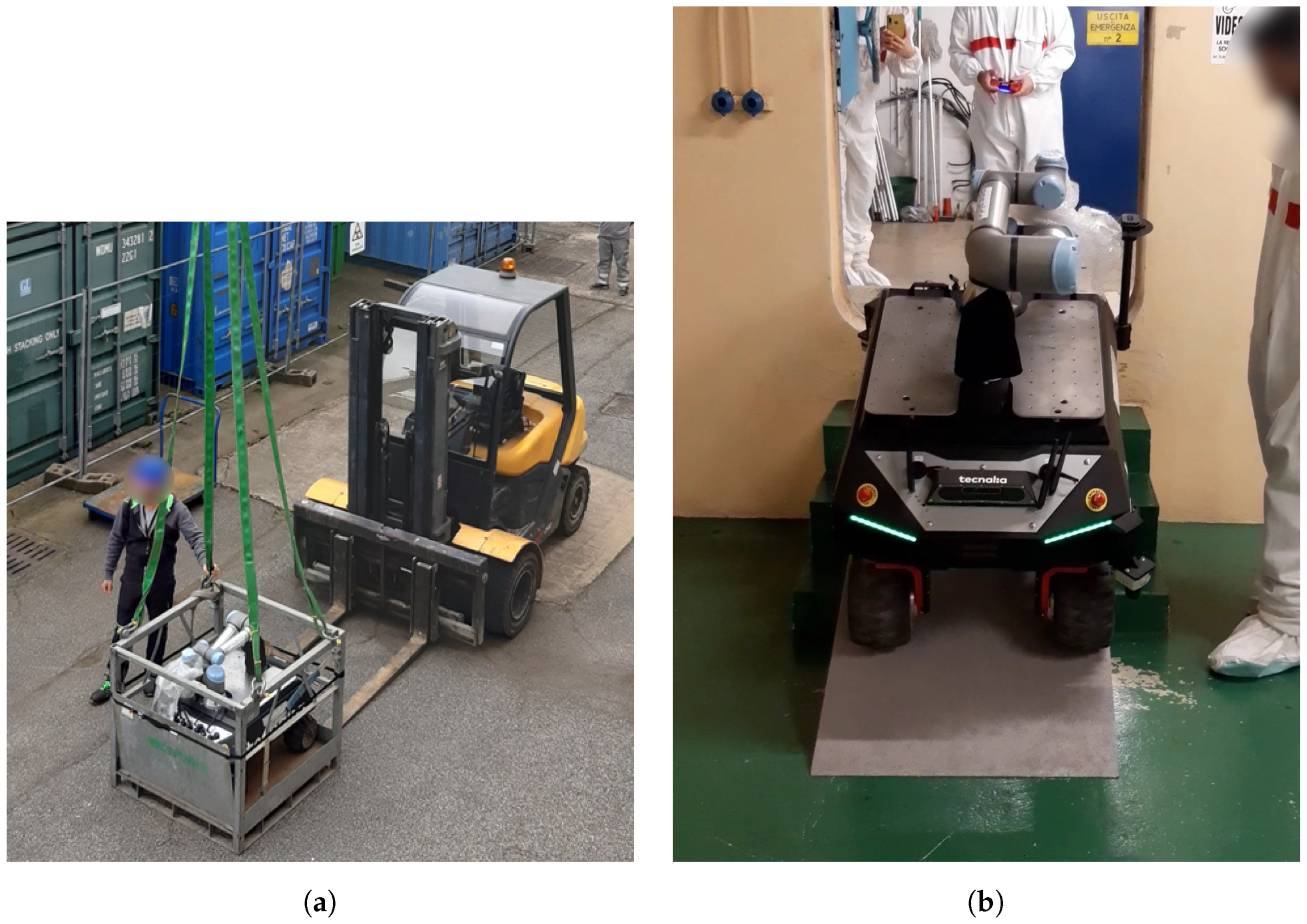
4.1. Integration Testing at TECNALIA and AiNT

The initial integration testing at TECNALIA was focused on the integration of the pole-mounted sensors (Figure 4) and validating the localization and autonomous capabilities of the UGV in a more generic non-nuclear indoor environment.
This early testing was successful. A number of issues were identified and fixed, such as the need for a configurable LiDAR mounting to avoid severe occlusions from the electronics boxes. The tested sensors were successfully mounted on the UGV and were able to draw power from the available connections. Data collected by the sensors were successfully gathered and relayed.
The second integration test at AiNT focused on integrating all of the available sensors in the four different configurations shown in Table 1, with special interest in the arm-mounted sensors. Due to the considerable size of some of the sensors, such as the PSD phoswitch, reachability tests were performed for both horizontal (Figure 5a) and vertical (Figure 5b) surfaces, for which the arm movements had to be carefully planned. This testing session was also used to characterize of the sensors with different radioactive sources.
Several rounds of testing were performed at AiNT in both teleoperated and autonomous modes to simulate the inspection of a room with nuclear sources. The compiled 2.5D navigation suite described in Section 2.2.2 was used to generate a map of the test site (Figure 6a). In both modes, the path followed and the measurement poses used by the DT were provided by the HDL 3D localization module. In the case of the arm-mounted sensors, this pose was combined with the arm’s joint states provided by the arm’s ROS driver (Figure 6b). Multiple sources were used in different rounds for the characterization of the sensors. Figure 7b shows the radiological map obtained from a 137Cs + 60Co source placed over a small cabinet in the top left area of the map, as shown in Figure 7a. This map was generated by the DT’s PoStLam tool using the measurements provided by the GAMON-DRONE and SNIPER-GN sensors in combination with the poses provided by the UGV, then overlaid on the map generated by the navigation suite’s mapping module (LIO-SAM).
This second integration session was also successful. As a result of this testing, some modifications to the arm’s tooling were necessary in order to improve the mounting and dismounting of the sensor. Minor problems with the data management were also identified and fixed.

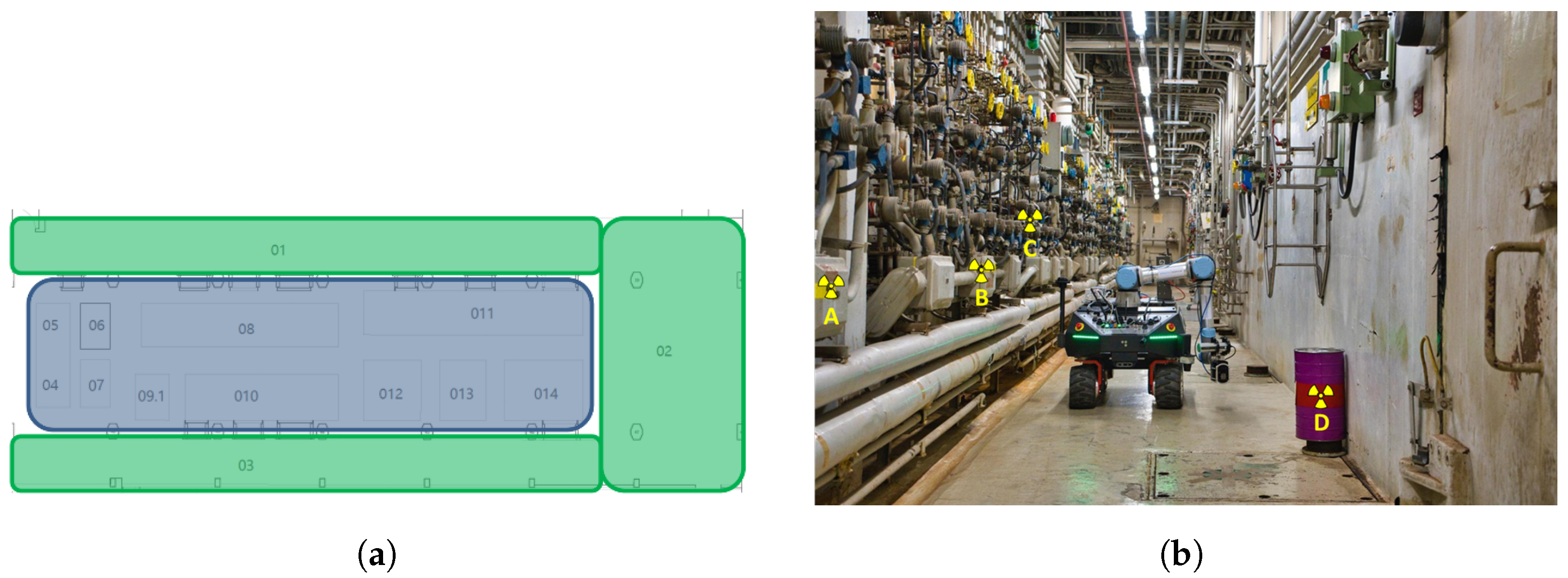
4.2. Demonstrator at the EUREX Plant

For the final demonstrator and assessment of deployment challenges in a real nuclear site, a final test and demo were carried out at the EUREX plant in Saluggia (Italy). This final demo was scheduled as a two-day event. On the first day, the system would be deployed in a new site while measuring the deployment time, any logistical problems faced, and the system’s ability to operate in and characterize the new environment. The second day was used for a demonstration with invited stakeholders. The system would be operating inside the nuclear site, simulating a whole shift with several inspection rounds during which the attendants would assist.
One of the main challenges for deploying the system to the new site was accessibility. In addition to personal safety and security measures that the operators had to follow, physical access to the site was restricted by long stairs, narrow corridors, and double mutually-interlocking doors. The UGV had to first be placed on the site with a crane (Figure 8a), then use a ramp to overcome a steep flight of stairs (Figure 8b).
The second challenge was the ability of the mapping/localization system to properly work in the demo environment. This consisted of a U-shaped section with long service tunnels around several fuel processing cells (Figure 9a). Those corridors were filled with pipes in the ceiling and along one of the walls, making it difficult for the 3D LiDAR to perceive the structural shape of the building. Several radioactive sources were placed in the corridor for the demo (Figure 9b):
  • Point A: source containing 241Am + 10Be.
  • Point B: source containing 137Cs.
  • Point C: source containing 241Am.
  • Point D: real waste drum containing 241Am and a not quantified amount of Pu.
The availability of a prerecorded high-quality 3D reconstruction of the site (Figure 10a) allowed us to test the setup of the UGV in the operational environment following two approaches: first using the prerecorded map, then using a map of the environment generating during the first run.
Initially, there were some concerns about the potential quality of the map generated in situ due to the characteristics of the environment, as mentioned before; however, the resulting map was of good quality (Figure 10c). The floor and walls were accurately captured, resulting in good localization results. Although the system was unable to map the pipe-filled ceiling, this did not seem to impact localization accuracy and robustness in the corridor.
Testing with the prerecorded map was also successful, attaining even better results than the map generated in situ. The higher point density of the high-resolution map allowed for better reconstruction of the floor surface even when using a lower-resolution subsampled version (Figure 10b). This resulted in a cleaner computed transitability map, which in turn enabled smoother path planning in autonomous mode. The prerecorded 3D reconstruction included color information; thus, this model was used by the DT, as color greatly enhances users’ understanding of the model. As the test had been successful, this was also the map used for UGV localization during the demo. This avoided the need to align both models, as both localization and the DT used a model with the same origin.
The UGV was able to navigate the environment and successfully bring the sensors close to the samples. The data recorded by the sensors was successfully retrieved by the DT from the internal storage, allowing a visual characterization of the test site to be created (Figure 11).
The results achieved by the UGV during the demo were satisfactory. The system was able to properly model a difficult environment as well as to self-localize and navigate inside of it. In addition, the system showed its ability to work using prerecorded data. Because the initial mapping requires a connection with the control station, this can greatly help in speeding up deployment at new sites or even at sites with difficult access by allowing full autonomous operation from the start. The localization also showed great robustness in a difficult environment (a corridor with few structural features). The system was able to operate continuously for the whole duration of the demo day (roughly 8 hours, equivalent to a full shift) without relevant localization drift, even in situations with high sensor occlusion (people gathered around the UGV).

5. Conclusions

This work reports a UGV used as a mobile platform for deploying a variety of nuclear sensors in the context of D&D operations at nuclear sites. The UGV and sensors integrate into a DT platform that allows for improved monitoring and management of operations. The present work has focused mainly on three aspects: first, the challenges of integrating a variety of sensors, many of which are not designed with integration into a UGV in mind, including issues around mounting, power, communications, and data management; second, providing accurate and robust localization and autonomous operation; and finally, the challenges involved in deploying such a system in a new site, especially considering the accessibility restrictions and special characteristics of nuclear sites.
Many aspects relevant to the operation of robots in nuclear environments have not been considered in the scope of this work. Loss of remote communications, endurance against harsh conditions, protection against contamination, air filtering, and avoidance of specific materials or battery technologies are some of the issues that can be critical when operating in such environments. Limited resources in terms of both materials and human hours prevented our addressing these problems, as we learned from our previous experience in the development of the RIANA robot [8]. In that case, all of the mentioned issues were specifically covered, especially regarding communications (deploying several solutions, including multiple robot systems to relay communications and carry out recovery behaviors in case of communication loss, e.g., autonomous back-tracking of the followed path until communication is recovered). Because the main objective of the CLEANDEM project is to test the functionality of the system and its potential impact on D&D operations, it was considered that these issues could be tackled later in further developments; thus, they are mentioned here as future work. The risk of contamination and equipment reuse was addressed by the project, in which protection against radiation and contamination as well as cleaning procedures were studied. A guideline with design recommendations and solutions to prevent contamination along with recommendations for cleaning and the reuse of the system has been published as one of the CLEANDEM project’s deliverables [35].
One of the main contributions is the development of a flexible system through the customization of a commercial AMR able to embed multiple sensors with different power and data communication requirements and with different mechanical mounting options (plate, arm, and pole). Up to six different sensors can be combined in four configurations, allowing the system to adapt to varied missions and speed up operations by following a reconfigurable and modular approach. The sensors are synchronized and their gathered data is integrated into a Digital Twin.
Another relevant contribution is the compilation of a 2.5D ROS-based navigation suite using independent and currently available modules that provide different functionalities in a single mapping/localization/navigation solution. This navigation solution proved to be accurate and robust in the test environments when using both prerecorded and auto-generated maps, allowing for both teleoperation and first-mission autonomous operation. The UGV was able to operate continuously for approximately one full shift without needing to reset or adjust the localization.
Finally, the deployment and setup of the UGV and the whole CLEANDEM solution were tested successfully in a real nuclear site demo. The accessibility challenges were overcome thanks to the size and dynamic characteristics of the vehicle, which allowed it to be easily lifted by a crane, pass through narrow doors, and climb steep slopes. The full setup of the system, mapping, and radiological characterization of the test site could be performed in less than one full shift, including all the overhead of safety and security that the operators had to pass through. The assessment of the test results [36] showed that adoption of the CLEANDEM solution could considerably reduce time and operator/hours required for operations in comparison with current procedures. The system also received very positive feedback from the stakeholders attending the demo event, who considered that such a system would be very useful in D&D and other operations.
The system, and especially the UGV, still lacks some features required to make it a fully-fledged system for actual D&D operations. In addition to the previously mentioned design and mechanical aspects, future work should focus on proper HMIs for teleoperation/monitoring as well as for autonomous mission configuration, management, and control.

Author Contributions

Conceptualization, I.V. and J.L.O.; methodology, I.V. and A.U.; software, I.V.; validation, I.V. and A.U.; formal analysis, I.V. and J.L.O.; investigation, I.V.; resources, I.V., A.U. and J.L.O.; writing—original draft preparation, I.V.; writing—review and editing, I.V., A.U. and J.L.O. All authors have read and agreed to the published version of the manuscript.

Funding

This research was funded by the Euratom research and training programme 2019–2020 under grant agreement No. 945335 (CLEANDEM Project). Views and opinions expressed are those of the author(s) only and do not necessarily reflect those of the European Union or Euratom. Neither the European Union nor Euratom can be held responsible for them.

Data Availability Statement

Many of the data generated (logs, maps, papers, presentations) are publicly available in the CLEANDEM project’s Zenodo repository at https://zenodo.org/communities/cleandem_project (accessed on 12 June 2024).

Conflicts of Interest

The authors declare no conflicts of interest. The funders had no role in the design of the study, in the collection, analysis, or interpretation of data, in the writing of the manuscript, or in the decision to publish the results.

Abbreviations

The following abbreviations are used in this manuscript:
2DTwo-Dimensional
3DThree-Dimensional
AMRAutonomous Mobile Robot
DCDirect Current
D&DDismantling and Decommissioning
DTDigital Twin
FTPFile Transfer Protocol
GPSGlobal Positioning System
HMIHuman–Machine Interface
HWHardware
IMUInertial Measurement Unit
LiDARLight Detection And Ranging
NDTNormal Distribution Transform
NTPNetwork Time Protocol
P2PPoint-to-Point
PoEPower over Ethernet
ROSRobot Operating System
SWSoftware
UASUnmanned Aircraft System
UGVUnmanned Ground Vehicle
USBUniversal Serial Bus

References

  1. Trevelyan, J.; Hamel, W.R.; Kang, S.C. Robotics in Hazardous Applications. In Springer Handbook of Robotics; Siciliano, B., Khatib, O., Eds.; Springer International Publishing: Cham, Switzerland, 2016; pp. 1521–1548. [Google Scholar] [CrossRef]
  2. Industrial Safety Guidelines for Nuclear Facilities; International Atomic Energy Agency: Vienna, Austria, 2018; ISBN 9789201016171.
  3. Smith, R.; Cucco, E.; Fairbairn, C. Robotic Development for the Nuclear Environment: Challenges and Strategy. Robotics 2020, 9, 94. [Google Scholar] [CrossRef]
  4. Fisher, M.; Cardoso, R.C.; Collins, E.C.; Dadswell, C.; Dennis, L.A.; Dixon, C.; Farrell, M.; Ferrando, A.; Huang, X.; Jump, M.; et al. An Overview of Verification and Validation Challenges for Inspection Robots. Robotics 2021, 10, 67. [Google Scholar] [CrossRef]
  5. Yokokohji, Y. The Use of Robots to Respond to Nuclear Accidents: Applying the Lessons of the Past to the Fukushima Daiichi Nuclear Power Station. Annu. Rev. Control Robot. Auton. Syst. 2021, 4, 681–710. [Google Scholar] [CrossRef]
  6. Vitanov, I.; Farkhatdinov, I.; Denoun, B.; Palermo, F.; Otaran, A.; Brown, J.; Omarali, B.; Abrar, T.; Hansard, M.; Oh, C.; et al. A Suite of Robotic Solutions for Nuclear Waste Decommissioning. Robotics 2021, 10, 112. [Google Scholar] [CrossRef]
  7. Ou, Y.; Xu, B.; Cai, H.; Zhao, J.; Fan, J. An overview on mobile manipulator in nuclear applications. In Proceedings of the 2022 IEEE International Conference on Real-Time Computing and Robotics (RCAR), Guiyang, China, 17–22 July 2022; pp. 239–243. [Google Scholar] [CrossRef]
  8. Kanaan, D.; Dogny, S.; Varet, T. Robot for investigations and assessments of nuclear areas. In Proceedings of the 2015 4th International Conference on Advancements in Nuclear Instrumentation Measurement Methods and their Applications (ANIMMA), Lisbon, Portugal, 20–24 April 2015; pp. 1–4. [Google Scholar] [CrossRef]
  9. Będkowski, J. Introductory Chapter: Autonomous Mobile Mapping Robots— Current State and Future Real-World Challenges. In Autonomous Mobile Mapping Robots; IntechOpen: Rijeka, Croatia, 2023. [Google Scholar] [CrossRef]
  10. Groves, K.; Hernandez, E.; West, A.; Wright, T.; Lennox, B. Robotic Exploration of an Unknown Nuclear Environment Using Radiation Informed Autonomous Navigation. Robotics 2021, 10, 78. [Google Scholar] [CrossRef]
  11. Zhou, H.f.; Zhang, H.; Qiu, M.w. Radiation avoiding algorithm for nuclear robot path optimization. Ann. Nucl. Energy 2022, 169, 108948. [Google Scholar] [CrossRef]
  12. Chen, Z.; Wu, H.; Chen, Y.; Cheng, L.; Zhang, B. Patrol robot path planning in nuclear power plant using an interval multi-objective particle swarm optimization algorithm. Appl. Soft Comput. 2022, 116, 108192. [Google Scholar] [CrossRef]
  13. Konukbay, A.; Koluman, A. Swarm Robots in CBRN Decontamination: Enhancing Efficiency and Safety. J. Smart Syst. Res. 2023, 4, 72–81. [Google Scholar] [CrossRef]
  14. Szczurek, K.A.; Prades, R.M.; Matheson, E.; Rodriguez-Nogueira, J.; Castro, M.D. Multimodal Multi-User Mixed Reality Human–Robot Interface for Remote Operations in Hazardous Environments. IEEE Access 2023, 11, 17305–17333. [Google Scholar] [CrossRef]
  15. Tsitsimpelis, I.; Taylor, C.J.; Lennox, B.; Joyce, M.J. A review of ground-based robotic systems for the characterization of nuclear environments. Prog. Nucl. Energy 2019, 111, 109–124. [Google Scholar] [CrossRef]
  16. West, A.; Tsitsimpelis, I.; Licata, M.; Jazbec, A.; Snoj, L.; Joyce, M.J.; Lennox, B. Use of Gaussian process regression for radiation mapping of a nuclear reactor with a mobile robot. Sci. Rep. 2021, 11, 13975. [Google Scholar] [CrossRef] [PubMed]
  17. Gabrlik, P.; Lazna, T.; Jilek, T.; Sladek, P.; Zalud, L. An automated heterogeneous robotic system for radiation surveys: Design and field testing. J. Field Robot. 2021, 38, 657–683. [Google Scholar] [CrossRef]
  18. Bird, B.; Nancekievill, M.; West, A.; Hayman, J.; Ballard, C.; Jones, W.; Ross, S.; Wild, T.; Scott, T.; Lennox, B. Vega—A small, low cost, ground robot for nuclear decommissioning. J. Field Robot. 2022, 39, 232–245. [Google Scholar] [CrossRef]
  19. Michel, M.; Amoyal, G.; Schoepff, V. CLEANDEM, a Cyber physicaL Equipment for unmAnned Nuclear DEcommissioning Measurements. EPJ Web Conf. 2023, 288, 07004. [Google Scholar] [CrossRef]
  20. Cyber physicaL Equipment for unmAnned Nuclear DEcommissioning Measurements|CLEANDEM Project|Fact Sheet|H2020. Available online: https://cordis.europa.eu/project/id/945335 (accessed on 12 June 2024).
  21. Outón, J.L.; Villaverde, I.; Herrero, H.; Esnaola, U.; Sierra, B. Innovative Mobile Manipulator Solution for Modern Flexible Manufacturing Processes. Sensors 2019, 19, 5414. [Google Scholar] [CrossRef] [PubMed]
  22. Outón, J.L.; Merino, I.; Villaverde, I.; Ibarguren, A.; Herrero, H.; Daelman, P.; Sierra, B. A Real Application of an Autonomous Industrial Mobile Manipulator within Industrial Context. Electronics 2021, 10, 1276. [Google Scholar] [CrossRef]
  23. RB-VOGUI Mobile Robot-Outdoor Mobile Robot|Robotnik®. Available online: https://robotnik.eu/products/mobile-robots/rb-vogui-en/ (accessed on 12 June 2024).
  24. Stanford Artificial Intelligence Laboratory-Robotic Operating System. Available online: https://ros.org/ (accessed on 12 June 2024).
  25. UR5e Lightweight, Versatile Cobot. Available online: https://www.universal-robots.com/products/ur5-robot/ (accessed on 12 June 2024).
  26. Shan, T.; Englot, B.; Meyers, D.; Wang, W.; Ratti, C.; Rus, D. LIO-SAM: Tightly-coupled Lidar Inertial Odometry via Smoothing and Mapping. In Proceedings of the 2020 IEEE/RSJ International Conference on Intelligent Robots and Systems (IROS), Las Vegas, NV, USA, 24 October 2020–24 January 2021; pp. 5135–5142. [Google Scholar] [CrossRef]
  27. Koide, K.; Miura, J.; Menegatti, E. A portable three-dimensional LIDAR-based system for long-term and wide-area people behavior measurement. Int. J. Adv. Robot. Syst. 2019, 16, 1729881419841532. [Google Scholar] [CrossRef]
  28. Magnusson, M.; Lilienthal, A.; Duckett, T. Scan registration for autonomous mining vehicles using 3D-NDT. J. Field Robot. 2007, 24, 803–827. [Google Scholar] [CrossRef]
  29. Fankhauser, P.; Hutter, M. A Universal Grid Map Library: Implementation and Use Case for Rough Terrain Navigation. In Robot Operating System (ROS): The Complete Reference (Volume 1); Koubaa, A., Ed.; Springer International Publishing: Cham, Switzerland, 2016; pp. 99–120. [Google Scholar] [CrossRef]
  30. Lu, D. global_planner. Available online: https://wiki.ros.org/global_planner (accessed on 12 June 2024).
  31. Rösmann, C.; Hoffmann, F.; Bertram, T. Integrated online trajectory planning and optimization in distinctive topologies. Robot. Auton. Syst. 2017, 88, 142–153. [Google Scholar] [CrossRef]
  32. Rossi, F.; Cosentino, L.; Longhitano, F.; Minutoli, S.; Musico, P.; Osipenko, M.; Poma, G.E.; Ripani, M.; Finocchiaro, P. The Gamma and Neutron Sensor System for Rapid Dose Rate Mapping in the CLEANDEM Project. Sensors 2023, 23, 4210. [Google Scholar] [CrossRef] [PubMed]
  33. RINA-CSM. Q-Pro2–Process, Plant, Production Monitoring Platform; Zenodo: Boston, MA, USA, 2024. [Google Scholar] [CrossRef]
  34. ORANO. PoStLAM Software (Presentation and Videos). 2024. Available online: https://zenodo.org/records/11191197 (accessed on 12 June 2024).
  35. Theroine, C. D7.3 Design to facilitate cleaning and reuse of robotics platforms. CLEANDEM project’s deliverable submitted to the EC. 2024. [Google Scholar]
  36. Pancotti, F.; Sciacqua, R. D9.4 Report on Final Demo. CLEANDEM project’s deliverable submitted to the EC. 2024. [Google Scholar]
Figure 1. Modules of the 2.5D navigation suite: (a) 3D map generated by the LIO-SAM module, (b) floor surface extracted from the 3D map, and (c) transitability map computed from the extracted floor.
Robotics 13 00110 g001
Figure 2. Different sensor configurations as designed (ac) and as mounted on the UGV (dg). The pixelated detector uses the same mounting as the PSD phoswitch. (a) PSD phoswitch, (b) Nanopix3 + CTZ + MiniRadMeter and MiniSiLiF, (c) GAMON-DRONE + SNIPER-GN + MiniRadMeter and MiniSiLiF, (d) PSD phoswitch, (e) Nanopix3 + CTZ + MiniRadMeter and MiniSiLiF, (f) GAMON-DRONE + SNIPER-GN + MiniRadMeter and MiniSiLiF, (g) Pixelated detector.
Robotics 13 00110 g002
Figure 3. Communications network.
Robotics 13 00110 g003
Figure 4. UGV in Configuration 4 during testing at TECNALIA.
Robotics 13 00110 g004
Figure 5. Testing the reachability with the PSD phoswitch sensor on horizontal (a) and vertical (b) surfaces.
Robotics 13 00110 g005
Figure 6. Results from the AiNT tests: (a) map generated by the navigation suite and (b) followed path (red line) with measurement spots (green arrows) shown in the DT (image (b) courtesy of RINA-CSM).
Robotics 13 00110 g006
Figure 7. Results from the AiNT tests: (a) radioactive sources placement (highlighted with the orange circle) and (b) generated radiological map (image (b) courtesy of RINA-CSM and ORANO).
Robotics 13 00110 g007
Figure 8. UGV ready to be lifted by crane (a) and UGV accessing the site via ramp (b) (images courtesy of Sogin).
Robotics 13 00110 g008
Figure 9. Schema of the demo site (a) and UGV in the corridor with the radioactive samples (b) (images courtesy of Sogin).
Robotics 13 00110 g009
Figure 10. Prerecorded high definition 3D reconstruction of the demo site (a), the down-sampled version used as the map (b), and the map generated using LIO-SAM (c).
Robotics 13 00110 g010
Figure 11. (a) DT showing the path (red line), measurement poses (green arrows), (b) radiological map, and (c) hotspot analysis. (Images courtesy of RINA-CSM and ORANO).
Robotics 13 00110 g011
Table 1. Different sensor configurations available.
ConfigurationSensorsPowerDataArmPole
1Nanopix3PoEEthernetYesNo
CTZ compact sensorBatteryWiFiYesNo
MiniRadMeter & MiniSiLiF24 VEthernetNoNo
2PSD phoswitchBatteryWiFiYesNo
MiniRadMeter & MiniSiLiF24 VEthernetNoNo
3Pixelated detectorBatteryWiFiYesNo
MiniRadMeter & MiniSiLiF24 VEthernetNoNo
4GAMON-DRONEBatteryWiFiNoYes
SNIPER-GNBatteryWiFiNoYes
MiniRadMeter & MiniSiLiF24 VEthernetNoYes
Disclaimer/Publisher’s Note: The statements, opinions and data contained in all publications are solely those of the individual author(s) and contributor(s) and not of MDPI and/or the editor(s). MDPI and/or the editor(s) disclaim responsibility for any injury to people or property resulting from any ideas, methods, instructions or products referred to in the content.

