Article

Static Balancing of Wheeled-legged Hexapod Robots

by
Ernesto Christian Orozco-Magdaleno
1,
Daniele Cafolla
2,
Eduardo Castillo-Castaneda
1 and
Giuseppe Carbone
3,*
1
CICATA Instituto Politecnico Nacional –Unidad Queretaro, Querétaro 76090, Mexico
2
IRCCS Neuromed, 86077 Pozzilli, Italy
3
DIMEG, University of Calabria, 87036 Cosenza, Italy
*
Author to whom correspondence should be addressed.
Robotics 2020, 9(2), 23; https://doi.org/10.3390/robotics9020023
Submission received: 3 February 2020 / Revised: 30 March 2020 / Accepted: 2 April 2020 / Published: 7 April 2020
(This article belongs to the Special Issue Advances in Robotics and Mechatronics)

Abstract

:
Locomotion over different terrain types, whether flat or uneven, is very important for a wide range of service operations in robotics. Potential applications range from surveillance, rescue, or hospital assistance. Wheeled-legged hexapod robots have been designed to solve these locomotion tasks. Given the wide range of feasible operations, one of the key operation planning issues is related to the robot balancing during motion tasks. Usually this problem is related with the pose of the robot’s center of mass, which can be addressed using different mathematical techniques. This paper proposes a new practical technique for balancing wheeled-legged hexapod robots, where a Biodex Balance System model SD (for static & dynamic) is used to obtain the effective position of the center of mass, thus it can be recalculated to its optimal position. Experimental tests are carried out to evaluate the effectiveness of this technique and modify and improve the position of hexapod robots’ center of mass.

1. Introduction

Service robotics demands are increasing, and service robots need to be able to perform different tasks in distinct settings, with different terrain types that may be flat or uneven [1]. On one hand, wheeled mobile platforms are robust and facilitate fast displacement over flat or regular surfaces, but are limited in irregular or uneven terrains. On the other hand, legged mobile platforms require more effort to control and maintain stability, but can more easily displace through uneven terrains, since they only require isolated safe foot holds. Usually legged systems move slower than wheeled ones [2]. Due to the above, there is an increasing interest (see [3]) in developing novel mobile machines or robots with useful features to displace over almost any surface type, such as wheeled-legged robots.
Wheeled-legged robots combine the best features of two locomotion types: wheel efficiency and velocity alongside legged robots’ capability to deal with difficult terrains. Service activities where time can be a matter of life and death, such as search and rescue missions or hospital assistance, are examples of tasks that might benefit significantly from such systems [4,5,6,7,8,9,10,11,12,13,14,15,16,17,18,19]. These hybrid systems, robots with legs ending in wheels, can move by driving on the wheels while adjusting with legs to slow changes in terrain height. The robot switches to legged locomotion if larger obstacles prevent driving [2,3]. Although these kinds of robots are able to switch from one locomotion type to the other, most of the active research focuses on combining both locomotion types as an active suspension system as presented by De Viragh et al. [4], Carbone and collaborators [5], and Copilusi and colleagues [6,7]; these studies use a kinematics approach to generate velocity commands for wheels, and also consider incorporating the whole body dynamics of the root to generate torque commands for each of the joints, including the wheels [8]. In addition, other research, like that of Chen and colleagues [9] and Bai and co-workers [10], explores transformable robots which are able to transform their wheels into legs, or use them as legs to reproduce a wheeled or legged locomotion. Other valuable examples are reported in [11] to [16] with insight on kinematics, stiffness, dynamics, stability, path planning, and control aspects.
The equations of motion, including the non-holonomic constraints are incorporated into the control structure of a two-wheeled mobile robot [17]. Other studies, such as those of Carbone et al. [18,19], address the kinematics/statics/dynamics of a leg for design and control purposes. Wheeled-legged robots have motion and balance issues because of their conceptual design of implementing two locomotion types in each extremity; this causes the robot to swipe during a legged locomotion or vibrate during a wheeled locomotion (having straight legs). Such issues increase when the robot uses omnidirectional wheels or Mecanum wheels instead of common wheels, since these kinds of wheels have no controllable degrees of freedom (DoF), like the rollers of the Mecanum wheels.
This paper presents the static balancing of a wheeled-legged hexapod robot to adjust its center of mass to improve its motion an operation performance. A Biodex Balance System is used to obtain practically the real position of the center of mass of the robot. The obtained test results of such a balance system allow for recalculation of the robot’s center of mass using zero moment point criteria. Experimental results are discussed to show the performance improvement of the robot by carrying out its static balancing.

2. A Wheeled-Legged Hexapod Robot

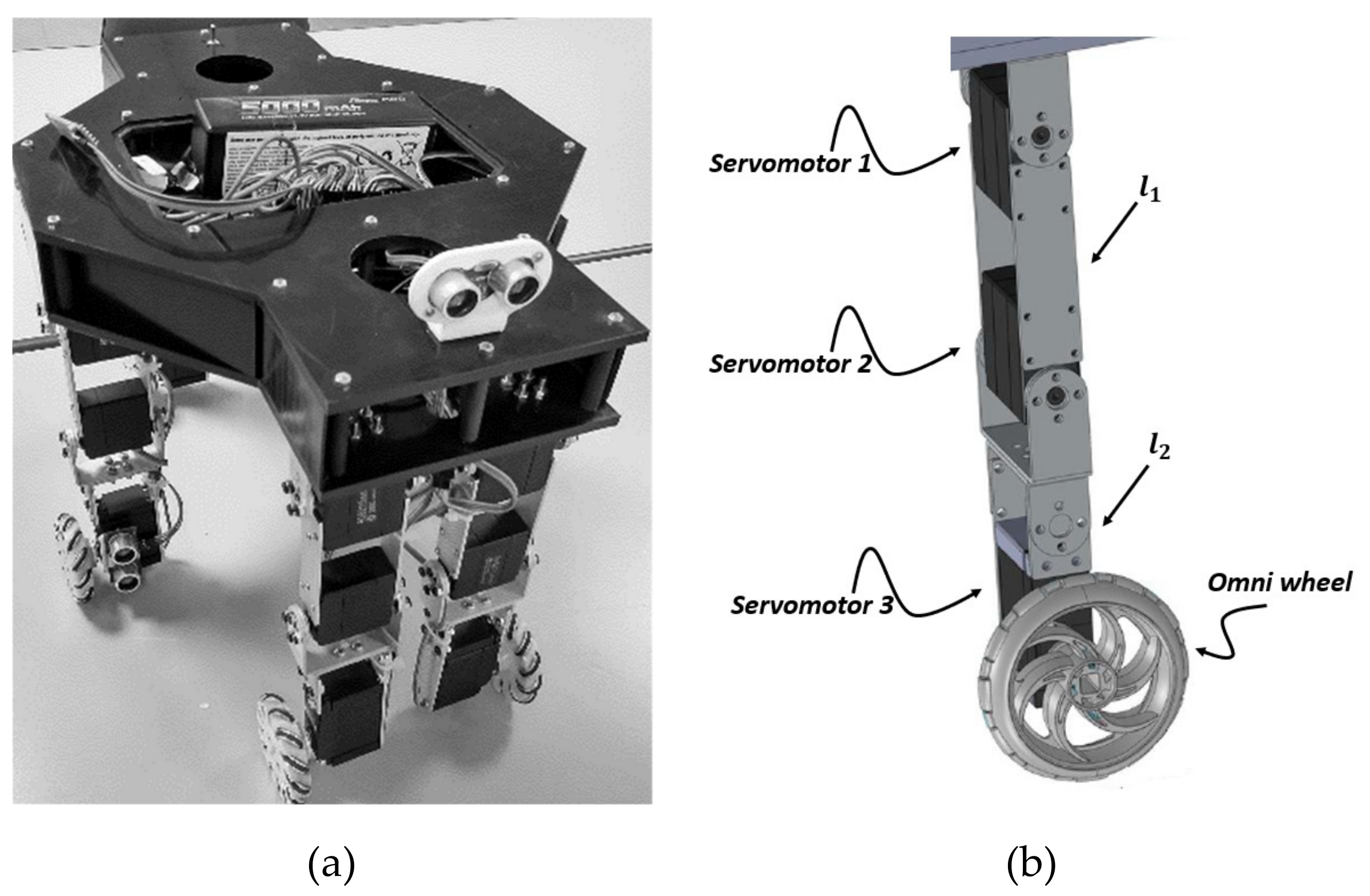
A family of wheeled-legged hexapod robots have been developed in Cassino since 2000. The main feature of this family of robots is their low-cost and user-friendliness based on a combination of legs and wheels intended for inspection and service at non-accessible locations, such as Montecassino Abbey, as well as tracking, assisting or directing tasks in hospitals, such as IRCCS Neuromed. The presented robot is a wheeled-legged hexapod robot (Figure 1a) with a Mecanum wheel in each leg as end-effector (EE) (Figure 1b), which means that its rollers are attached with a rotation axis of 45° to the plane of the wheel [20]. This robot has a lightweight three-dimensional (3D) printed body onto which six hybrid legs are connected to the chest. Its body can fit into a box of 375 × 230 × 200 mm, allowing for two front legs, two lateral legs (one on each side), and two rear legs, all in frontal orientation (Figure 2a). Its topological characteristics are presented in Table 1. Kinematic and dynamic models of the Cassino hexapod robot have been previously developed for legged locomotion using geometrical and Euler–Lagrange methods, respectively. A detailed description can be found in a study by Tedeschi and Carbone [13]. Every hybrid leg consists of three servomotors, two (180° servomotor) to enable the pure movement of the leg, and the third (continuous rotation servomotor) to activate the movement of the Mecanum wheel (Figure 2b). This kind of leg allows the robot to move in any direction over flat surfaces and to easily avoid large obstacles by simply rolling to any position along a straight line or overcoming small obstacles by performing complex movement with a combination of legs and wheels [19]. Its control hardware is fully onboard. It consists of an Arduino Mega as the servo-controller, a servo-shield to link the 18 servomotors, and a LiPo battery (full power 4S) with a voltage reduction regulator to 5 V. A schematic diagram of the control hardware is presented in Figure 3.
One of the main operational features of this robot is its ability to move or displace on various surfaces, such as smooth and rough surfaces. This feature allows it to perform various service tasks where it is necessary to move faster over a flat surface with wheeled locomotion or to move slower but safer with legged locomotion [19]. In addition, it can face rough terrains with legged locomotion, or by raising one or more legs during a wheeled displacement to avoid and overcome obstacles. This robot functionality is well illustrated by Orozco-Magdaleno et al. [20] and Ceccarelli and colleagues [21], who explore the possibility of a wheeled, legged, and wheeled-legged locomotion. Due to the Mecanum wheels, complex displacements can also be carried out, where the robot can follow a circular trajectory without altering its local x or y axis. All operation modes of the robot are embedded in its servo controller. Namely, one can select the operation mode that he/she wishes to use. The gait planning is based on the implementation of a kinematic model, whose main formulation is reported by Tedeschi and Carbone [13] for the legged locomotion. Moreover, a specific kinematic model has also been implemented for the omni-wheeled locomotion. A user-friendly Android app was developed to implement a user interface when selecting and implementing the desired legged and omni-wheeled operation modes (see [19,20]).
The robot has an Inertial Measurement Unit (IMU) sensor mounted on its platform as a feedback on its angular displacement; it has an MPU6050 unit coupled with a 3-axis gyroscope and a 3-axis accelerometer on the same silicon along with an onboard digital motion processor (DMP) capable of processing complex 9-axis motion fusion algorithms.

3. Static Balancing

The goal of mobile robots is to extend the capabilities and increase the safety of human beings during dangerous service operations or environments. During these service operations, mobile robots can face different motion issues due to surface properties; the walking robots can fall, or the mobile robots can stop rolling or overturn. In addition to the above, the mechanical assembly of the robot is very important since it defines the real position of the center of mass of the robot. Therefore, there are different techniques to assure the static and dynamic balancing of the robots. An easy way to solve this problem is to implement a static balancing of the robot, using any technique to ensure the correct posture of the body with respect to the plane or surface. Static balancing is to balance the gravity so that the weight of the machine components does not produce any force at the actuators under static conditions, this also allows to correct the posture of the robot´s body. On the one hand, Wen-Yu and Lei [22] presented a static balancing method for a quadruped robot, where the stability margin of the robot and the unstable problems during a walk were studied. On the other hand, in a study by Magid and colleagues [23], a static balancing algorithm for a mobile robot with caterpillar was presented, where a function calculates the optimal position of the center of mass, depending on the terrain type and obstacle types to overcome. The other solution is to implement dynamic balancing, where a sensor’s implementation is necessary to calculate and evaluate in each time lapse the optimal posture of the robot. Dynamic balancing is to balance the inertia so that the dynamic force change can be cancelled or minimized. The balancing issue becomes worst when the robot has a hybrid locomotion configuration, like the wheeled-legged or omni-wheeled-legged locomotion. Therefore, this problem should be solved by considering each locomotion type separately and together. In particular, this paper solves this problem by carrying out a static balancing to solve the ground contact and the foot hold of the robot by compensating the unbalancing with a counterweight fixed in the robot´s body. The static balancing is carried out with the obtained experimental data of a Biodex Balance System model SD (for static & dynamic). This balance system calculates in real-time the position of the center of the mass of the robot, thus it can be recalculated and compensated by adding weight to another part of the robot’s body.

3.1. Balancing Issues in Motion Operation

An important key issue during motion operations is the stability of the wheeled-legged hexapod robot. This problem can be classified in two different types: dynamic (running, rolling, and hopping) and static (walking). In static stability, the vertical projection of the center of mass of the robot must always be within the support polygon of the legs which have ground contact (Figure 4). Dynamic stability is needed when the center of mass (CoM) is outside or on the border of the support polygon. When the CoM is outside of the support polygon, the robot will fall over when no additional forces and movement are made with the legs [24]. For an arbitrary support polygon, the stability margin is the shortest distance from the vertical projection of the center of gravity to any point on the boundary of the support pattern in the horizontal plane [24]. There are other solutions for solving the stability problem, like the one described by Murray and Sastry [25], where the criterion of the zero moment point (ZMP) is presented. ZMP is defined as the point on the ground where the net moment of the inertial forces and the gravity forces has no component along the horizontal axes. For a dynamic stable locomotion, it is necessary to have the ZMP in the support polygon at all stages of the locomotion gait [26,27].

3.2. Biodex Balance System SD

The Biodex Balance System SD is a medical device for neuro rehabilitation, vestibular physiotherapy, and balance training. This device was designed to improve balance, increase agility, develop muscle tone, and treat a wide variety of pathologies. The two main parts of the system are the display module, where the user can choose between balance analysis or training, and the foot platform, where the patient is located for the evaluation. The primary components of the Biodex Balance System SD are presented in Figure 5a. This system has four different analysis formats: postural stability, limits of stability, athlete single leg, and fall risk. In particular, the postural analysis, our area of interest, allows to evaluate the real center of mass of the patient, or of the robot in this case, by producing random movements or shakes with the foot platform to destabilize the patient. The postural stability testing screen is presented in Figure 5a, where it shows the real position of the center of mass of the patient in respect to the foot platform.

Tests

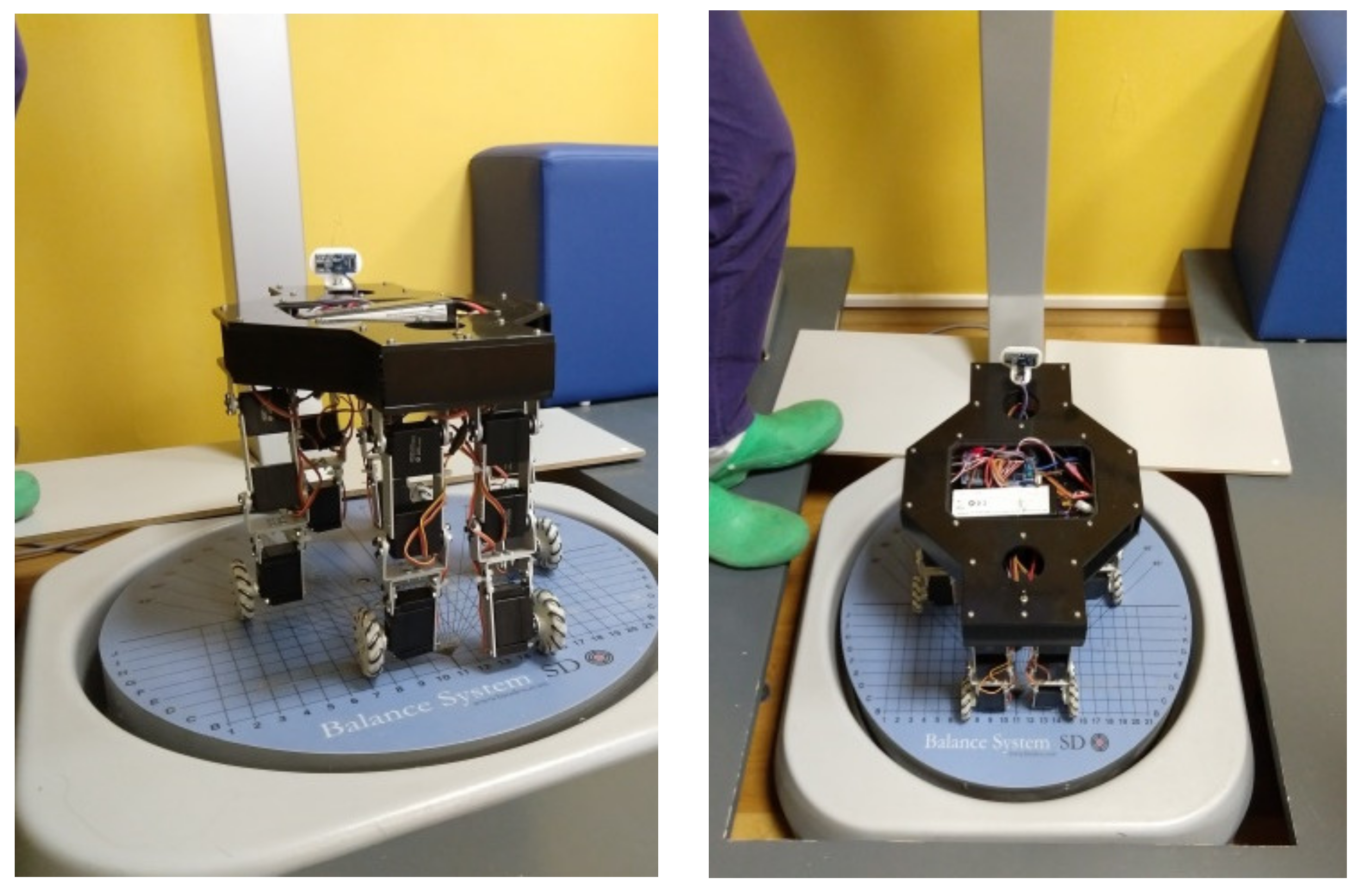
Two postural tests were carried out with the aforementioned wheeled-legged hexapod robot. Regarding the above system, the robot is located at the center of the foot platform (Figure 6). Each test is composed of one test trial of 10 s, with a platform setting in one (the bigger instability), and a stance for both feet. The test results are presented in Figure 7 and Table 2. The test results of the balance system report the balance trace in a graphic, which shows the real position of the CoM of the robot in each movement that is needed to become stabilized. It also presents two numerical values, the medial/lateral and the anterior/posterior.
The medial/lateral (M/L) stability index represents the variance of foot platform displacement in degrees, from level, for motion in the frontal plane, and is represented by Equation (1), where COB is the initial center of balance, zero; X is the displacement in degrees of the COB over the x axis along the test; and 200 is the number of samples. The anterior/posterior (A/P) stability index represents the variance of foot platform displacement in degrees, from level, for motion in the sagittal plane, and is represented by Equation (2), where Y is the displacement in degrees of the COB over the y axis along the test. Thus, according with the test results presented in Table 2, the center of mass of the robot moves 0.36° over the x axis and 0.42° over the y axis. To compensate the mismatch of the center of mass of the robot, the zero moment point (ZMP) criteria is applied in the next section.
DI x = COB   -   X 2 number   of   samples
DI y = COB   -   Y 2 number   of   samples

3.3. Zero Moment Point Criterion

Apart from the realization of the relative motion of the mechanism’s links, the most important task of a locomotion mechanism during the motion is to preserve its balance or stability, which is achieved by ensuring the foot’s ground contact. In general, the total ground reaction consists of three components of the force R (Rx, Ry, Rz) and moment M (Mx, My, Mz) [29]. Since the friction force acts at the point of contact of the foot with the ground, and the foot on the ground is at rest, those components of the force R and moment M that act in the horizontal plane will be balanced by friction. Therefore, the horizontal reaction force (Ry, Rz) represents the friction force that is balancing the horizontal component of the force FA, whereas the vertical reaction moment My represents the moment of friction reaction forces that balances the vertical component of the moment MA and the moment induced by the force FA [30]. Thus, the zero moment point (ZMP) is defined as that point on the ground at which the net moment of the inertial forces and the gravity forces has no component along the horizontal axes. According with Table 2, the CoM of the robot is displaced 0.36° over the x axis and 0.42° over the z axis, namely, the robot’s whole body is unbalanced (Figure 8). In the particular case of the wheeled-legged hexapod robot, it is necessary to compensate the reaction Ry on the opposite corner of the robot´s body (Figure 9). The static model of the robot is carried out by solving its free-body diagram, considered statically to calculate the reacting forces (Figure 9 and Figure 10). Figure 10 presents the force distributions of the robot, where W is the weight of the robot, a uniformly distributed load, which behaves as an acting force; R forces are the reacting forces from the legs for a static equilibrium. Considering the unbalancing presented in Figure 8, and the diagram of Figure 9, it is necessary to add an extra weight to balance the system. Thus, by implementing Equations (3) and (4), where Ry is the total reaction force and W Extra is the extra weight to compensate the unbalancing, the counterweight is defined according to the equilibrium equations, which can be written for the model in Figure 10 in the simplified form
R Y = R 1 + R 2 + R 3 + R 4 + R 5 + R 6
F Y = - W + R Y - W Extra = 0
Specifically, for this robot the compensation of the robot´s unbalancing is solved by adding an extra weight of WExtra = 250 g at the location shown in Figure 11. The position of the counterweight is defined by the total lengths of the robot to compensate the total static unbalancing. Achievement of a proper balancing is then verified using the Biodex Balance System SD as shown in Figure 5 and Figure 6.

4. Experimental Tests

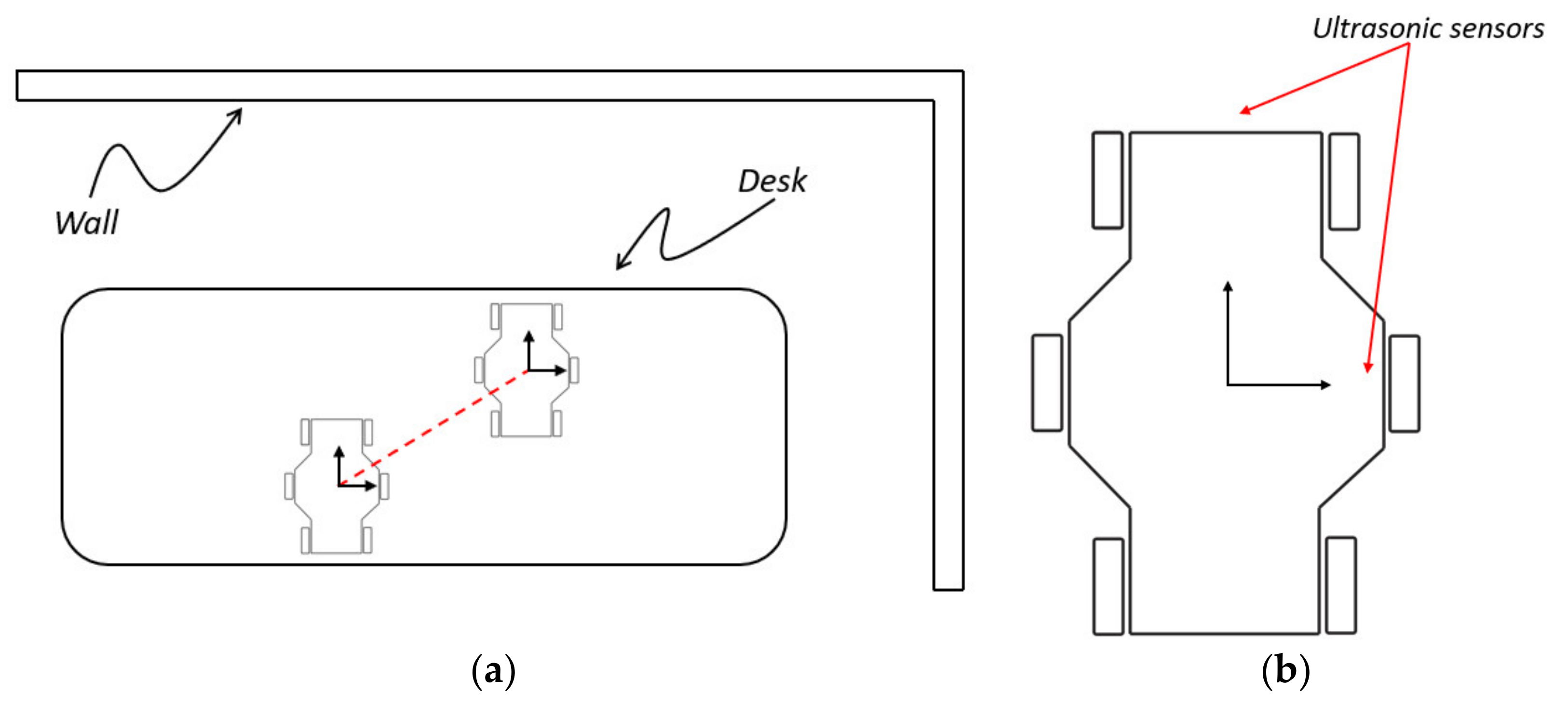
Experimental tests were carried out to verify the correction of the balance of the robot. Such tests were carried out with the balanced and unbalanced robots. For the tests, an omni-wheeled locomotion operation was selected, where the robot follows a diagonal path (Figure 12a). Ultrasonic sensors are fixed over the robot to measure the displacement of the robot (Figure 12b). On the one hand, Figure 13 presents the photo sequence of the test with unbalancing, where it can be observed that the robot is not able to follow the proposed path. The above is due to the wheels’ ground contact; since it is not equal in each leg, Mecanum wheels do not roll well. In each time lapse, the robot tries to displace, but the low ground contact in some of the legs is stopping the robot and also turning it. On the other hand, Figure 14 presents the photo sequence of the test when the robot is balanced and able to follow and complete the proposed path. The above is due to correct ground contact of the wheels. In each time lapse it is observed that the robot is rolling smoothly. Tests results are presented in Figure 15. Figure 15a presents the comparison between the target and the real displacement of the robot when it is unbalanced. In this case, it can be shown that the robot does not reach the target value of 60 cm, instead it reaches just 36 cm. In addition, it can be observed that during the displacement the robot has different perturbations, which make the robot oscillate. Figure 15b presents the comparison between the target and the real displacement of the robot when it is balanced. It can be observed that the robot displaces with a better linearity and less oscillations. The robot reaches the target value with an overshoot of 2 cm. Therefore, the proposed method for the static balancing of the wheeled-legged hexapod robot is correct. Correct balancing and ground contact of the robot is very important to improve its motion performance significantly.

5. Conclusions

This paper addresses the balance and ground contact of the wheels and legs for wheeled-legged hexapod robots. In particular, the center of mass location has proven to play a significant role in the practical operation strategies of multi-legged locomotion. Accordingly, this paper proposes a static balancing procedure to achieve proper robot locomotion. The main contribution of the paper is the implementation of a practical method to obtain the center of mass of the robot by using a Biodex Balance System SD. This method allows to identify and correct the center of mass location. Experimental tests demonstrated the improved motion performance of the wheeled-legged hexapod robot during an omni-wheeled operation. Thus, the robot can move or displace from any point A to any point B in less time, being able to carry out service activities, like search and rescue or hospital assistance, where time is of great importance. Accordingly, the proposed static balancing procedure can be applied in other mobile robots to improve their motion performance.

Author Contributions

Conceptualization, D.C. and G.C.; software, D.C. and E.C.O.-M.; validation, D.C. and E.C.O.-M.; data curation, D.C. and E.C.O.-M.; writing—original draft preparation, D.C. and E.C.O.-M.; writing—review and editing, E.C.O.-M., G.C. and D.C.; supervision, G.C., D.C., and E.C.-C. All authors have read and agreed to the published version of the manuscript.

Funding

This is a self-funded project.

Acknowledgments

The first author wishes to thank CONAYCT and ACRI association for grants which supported him for a period of study under the supervision of Prof. Giuseppe Carbone.

Conflicts of Interest

The authors declare no conflict of interest.

References

  1. Orozco-Magdaleno, E.C.; Cafolla, D.; Castillo-Castañeda, E.; Carbone, G. A Service Hexapod Robot as Hospital Guide. Int. J. Mech. Control. 2019, 20, 121–126. [Google Scholar]
  2. Schwarz, M.; Rodehutskors, T.; Schreiber, M.; Behnke, S. Hybrid driving-stepping locomotion with the wheeled-legged robot Momaro. In Proceedings of the 2016 IEEE International Conference on Robotics and Automation (ICRA); 2016; pp. 5589–5595. [Google Scholar]
  3. Carbone, G.; Gomez-Bravo, F. Motion and Operation Planning of Robotic Systems: Background and Practical Approaches; Springer: Dordrecht, The Netherlands, 2015. [Google Scholar]
  4. De Viragh, Y.; Bjelonic, M.; Bellicoso, D.; Jenelten, F.; Hutter, M. Trajectory Optimization for Wheeled-Legged Quadrupedal Robots Using Linearized ZMP Constraints. IEEE Robot. Autom. Lett. 2019, 4, 1633–1640. [Google Scholar] [CrossRef] [Green Version]
  5. Carbone, G.; Shrot, A.; Ceccarelli, M. Operation Strategy for a Low-Cost Easy-Operation Cassino Hexapod. Appl. Bionics Biomech. 2007, 4, 149–156. [Google Scholar] [CrossRef] [Green Version]
  6. Copilusi, C.; Ceccarelli, M.; Carbone, G. Design and numerical characterization of a new leg exoskeleton for motion assistance. Robotica 2014, 33, 1147–1162. [Google Scholar] [CrossRef]
  7. Copilusi, C.; Ceccarelli, M.; Dumitru, N.; Carbone, G. Design and Simulation of a Leg Exoskeleton Linkage for a Human Rehabilitation System. In The 11th IFToMM International Symposium on Science of Mechanisms and Machines. Mechanisms and Machine Science; Visa, I., Ed.; Springer: Cham, Germany, 2014; Volume 18, pp. 117–125. [Google Scholar]
  8. Chen, W.-H.; Lin, H.-S.; Lin, Y.-M.; Lin, P.-C. TurboQuad: A Novel Leg–Wheel Transformable Robot With Smooth and Fast Behavioral Transitions. IEEE Trans. Robot. 2017, 33, 1025–1040. [Google Scholar] [CrossRef]
  9. Bai, L.; Hu, H.; Chen, X.; Sun, Y.; Ma, C.; Zhong, Y. CPG-Based Gait Generation of the Curved-Leg Hexpod Robot with Smooth Gait Transition. Sensors 2019, 19, 3705. [Google Scholar] [CrossRef] [Green Version]
  10. Bjelonic, M.; Bellicoso, D.; De Viragh, Y.; Sako, D.; Tresoldi, F.D.; Jenelten, F.; Hutter, M. Keep Rollin’—Whole-Body Motion Control and Planning for Wheeled Quadrupedal Robots. IEEE Robot. Autom. Lett. 2019, 4, 2116–2123. [Google Scholar] [CrossRef] [Green Version]
  11. Carbone, G.; Ceccarelli, M. A Low-Cost Easy-Operation Hexapod Walking Machine. Int. J. Adv. Robot. Syst. 2008, 5, 21. [Google Scholar] [CrossRef]
  12. Giordano, P.R.; Fuchs, M.; Albu-Schaffer, A.; Hirzinger, G. On the kinematic modeling and control of a mobile platform equipped with steering wheels and movable legs. In Proceedings of the 2009 IEEE International Conference on Robotics and Automation, Kobe, Japan, 12–17 May 2009; Institute of Electrical and Electronics Engineers (IEEE): Piscataway, NJ, USA; pp. 4080–4087. [Google Scholar]
  13. Tedeschi, F.; Carbone, G. Design of a Novel Leg-Wheel Hexapod Walking Robot. Robotics 2017, 6, 40. [Google Scholar] [CrossRef] [Green Version]
  14. Sentis, L.; Petersen, J.; Philippsen, R. Implementation and stability analysis of prioritized whole-body compliant controllers on a wheeled humanoid robot in uneven terrains. Auton. Robot. 2013, 35, 301–319. [Google Scholar] [CrossRef]
  15. Carbone, G.; Ceccarelli, M.; Oliveira, P.J.; Saramago, S.F.P.; Carvalho, J.C.M. Optimum Path Planning of CaPaMan (Cassino Parallel Manipulator) by Using Inverse Dynamics. Robot. Int. J. 2008, 26, 229–239. [Google Scholar]
  16. Carbone, G.; Lim, H.-O.; Takanishi, A.; Ceccarelli, M. Stiffness analysis of biped humanoid robot WABIAN-RIV. Mech. Mach. Theory 2006, 41, 17–40. [Google Scholar] [CrossRef]
  17. Orozco-Magdaleno, E.C.; Cafolla, D.; Castillo-Castañeda, E.; Carbone, G. Experimental Validation of a Gait Planning for Obstacle Avoidance Using Mecanum Wheels. In Advances in Mechanism and Machine Science. IFToMM WC 2019. Mechanisms and Machine Science; Uhl, T., Ed.; Springer Science and Business Media LLC.: Berlin/Heidelberg, Germany; Cham, Switzerland, 2019; Volume 73, pp. 2391–2400. [Google Scholar]
  18. Tedeschi, F.; Cafolla, D.; Carbone, G. Design and Operation of Cassino Hexapod II. Int. J. Mech. Control. 2014, 15, 19–25. [Google Scholar]
  19. Magdaleno, E.C.O.; Cafolla, D.; Ceccarelli, M.; Castillo-Castañeda, E.C.; Carbone, G. Experiences for a User-Friendly Operation of Cassino Hexapod III. In Advances in Service and Industrial Robotics. RAAD 2018. Mechanisms and Machine Science; Aspragathos, N., Koustoumpardis, P., Moulianitis, V., Eds.; Springer Science and Business Media LLC.: Berlin/Heidelberg, Germany; Cham, Switzerland, 2018; Volume 67, pp. 205–213. [Google Scholar]
  20. Magdaleno, E.C.O.; Carbone, G.; Castillo-Castañeda, E.C. Experiences on a Hybrid Locomotion Approach to Overcome Obstacles with Cassino Hexapod III. In Advances in Italian Mechanism Science. IFToMM ITALY 2018. Mechanisms and Machine Science; Carbone, G., Gasparetto, A., Eds.; Springer Science and Business Media LLC.: Berlin/Heidelberg, Germany; Cham, Switzerland, 2019; Volume 68, pp. 286–293. [Google Scholar]
  21. Ceccarelli, M.; Cafolla, D.; Russo, M.; Carbone, G. HeritageBot platform for service in Cultural Heritage frames. Int. J. Adv. Robot. Syst. 2018, 15, 1–13. [Google Scholar] [CrossRef]
  22. Wen-Yu, Z.; Lei, Z. Research of a static balance method for a quadruped robot walking on a slope. In Proceedings of the 2011 IEEE International Conference on Information and Automation, Shenzhen, China, 6–8 June 2011; Institute of Electrical and Electronics Engineers (IEEE): Piscataway, NJ, USA; pp. 261–266. [Google Scholar]
  23. Magid, E.; Tsubouchi, T.; Koyanagi, E.; Yoshida, T. Static Balance for Rescue Robot Navigation: Loosing Balance on Purpose within Random Step Environment. In Proceedings of the IEEE/RSJ International Conference on Intelligent Robots and Systems, Taipei, Taiwan, 18–22 October 2010; pp. 349–356. [Google Scholar]
  24. Mukherjee, R.; Anderson, D.P. A Surface Integral Approach to the Motion Planning of Nonholonomic Systems. J. Dyn. Syst. Meas. Control. 1994, 116, 315–325. [Google Scholar] [CrossRef] [Green Version]
  25. Murray, R.M.; Sastry, S. Nonholonomic motion planning: Steering using sinusoids. IEEE Trans. Autom. Control. 1993, 38, 700–716. [Google Scholar] [CrossRef] [Green Version]
  26. Vukobratovic, M.; Borovac, B. Zero-Moment Point – Thirty-Five Years of its Life. Int. J. Hum. Robot. 2004, 1, 157–173. [Google Scholar] [CrossRef]
  27. Belter, D.; Skrzypczynski, P. Integrated Motion Planning for a Hexapod Robot Walking on Rough Terrain. In IFAC Proceedings Volumes; Elsevier BV: Amsterdam, The Netherlands, 2011; Volume 44, pp. 6918–6923. [Google Scholar]
  28. Biodex. Balance System SD Operation/Service Manual. Available online: https://www.biodex.com/sites/default/files/950300man_08060.pdf (accessed on 31 March 2020).
  29. Jeong, S.; Takahashi, T. Wheeled inverted pendulum type assistant robot: Design concept and mobile control. Intell. Serv. Robot. 2008, 1, 313–320. [Google Scholar] [CrossRef]
  30. Vinay, A.; Sai Krishna, B.V.; Manoj, P.N.; Rao, N.A.; Muthy, K.N.B.; Natarajan, S. Person Identification in Smart Surveillance Robots using Sparse Interest Points. Procedia Comput. Sci. 2018, 133, 812–822. [Google Scholar]
Figure 1. Kinematic diagram of the wheeled-legged hexapod robot: (a) full robot; (b) detail of one leg.
Robotics 09 00023 g001
Figure 2. Wheeled-legged robot: (a) photograph of the robot; (b) one hybrid leg.
Robotics 09 00023 g002
Figure 3. Schematic diagram of the control hardware of the wheeled-legged hexapod robot.
Robotics 09 00023 g003
Figure 4. Stability margin and support pattern in a legged locomotion of a hexapod robot.
Robotics 09 00023 g004
Figure 5. The Biodex Balance System model SD (for static & dynamic): (a) primary components and adjustment mechanisms; (b) postural stability testing screen [28].
Robotics 09 00023 g005
Figure 6. The wheeled-legged hexapod robot located at the center of the foot platform.
Robotics 09 00023 g006
Figure 7. Results of experimental tests: (a) test 1; (b) test 2.
Robotics 09 00023 g007
Figure 8. Schematic diagram of the unbalancing of the robot.
Robotics 09 00023 g008
Figure 9. Schematic diagram of the static model of the wheeled-legged hexapod robot.
Robotics 09 00023 g009
Figure 10. Free-body diagrams: (a) schematics of full hexapod robot; (b) a detail of a single leg in fully stretched configuration.
Robotics 09 00023 g010
Figure 11. Compensation of the center of mass: (a) proposed, (b) real.
Robotics 09 00023 g011
Figure 12. Experimental tests with the wheeled-legged hexapod robot: (a) layout of the experimental test; (b) implementation of sensors over the robot.
Robotics 09 00023 g012
Figure 13. Photo sequence of the tested path with unbalancing: (a1) t = 0 s; (a2) t = 3 s; (a3) t = 6 s; (a4) t = 9 s; (a5) t = 12 s.
Robotics 09 00023 g013
Figure 14. Photo sequence of the tested path with balancing: (a1) t = 0 s; (a2) t = 3 s; (a3) t = 6 s; (a4) t = 9 s; (a5) t = 12 s.
Robotics 09 00023 g014
Figure 15. Experimental tests results, comparison between target and real displacement: (a) unbalanced; (b) balanced.
Robotics 09 00023 g015
Table 1. Topological characteristics of the robot.
LinkLength (mm)Mass (g)BodySize (mm)Mass (g)
L191.0105Length375.01035
L291.0112Width230.0
Wheel53.3108Hight 200.0
Table 2. Summarized test’s results.
Test NumberMedial Lateral (X axis) (°)Anterior/Posterior (Y axis) (°)
10.36–0.36
20.360.49