Abstract
Fused deposition technology (FDM), as an additive manufacturing (AM) technology, holds immense potential in the field of solid grain manufacturing. It can accomplish complex grain shaping with ultra-low-pressure ratios, which are challenging to achieve using conventional grain manufacturing processes. In this work, solid propellants with complex structures were made by using 3D printing. The obtained sample grains of the solid propellants had a complete structure, which conformed to the design model and had no obvious defects. Then, the combustion and mechanical properties of the printed solid propellant were obtained and analyzed. The results show that the composition of the printed solid propellant is more uniform and the performance is better than that of the conventional solid propellant. In addition, by conducting a motor experiment, it was verified that the 3D-printed grains with complex structures have the characteristic of an “ultra-low pressure ratio”. The comparative analysis revealed that the maximum working pressure was reduced by about 19.5%, the bearing load of the shell was reduced, and the mass of the shell and other bearing parts was reduced by 11.5%. The research in this paper shows that 3D-printed solid propellant technology can realize the formation of grains with complex structure, which can directly promote the solid rocket motor to obtain the “ultra-low pressure ratio” characteristic, and greatly improve the performance of solid rocket motors.
1. Introduction
With current propellant manufacturing technology, it is challenging to achieve the ultra-low-pressure ratio [1,2,3] complex grain formation where the ratio of maximum motor pressure to average pressure is close to 1. Compared with the preparation process of traditional solid propellants, 3D-printed solid propellant technology can realize “what you get is what you want” [4]. It is a direct molding method which is based on digital model definition and oriented to micro structures [5,6,7]. In addressing the challenges of “designability but difficulty in manufacturing” associated with current solid propellant processes [8,9], 3D printing technology provides a solution to the difficulties in achieving precise control over engine propellant performance [10] and accurate shaping of intricate structures. The capability it possesses for optimal engine structural design and enabling rocket performance enhancement highlights its vast potential for wide-ranging applications in the aerospace industry [11,12,13].
The greater the impulse mass ratio of the motor (i.e., the smaller the negative mass), the greater the range of the rocket [14]. The negative mass of the motor mainly comes from the shell, nozzle, and other structural parts, and the main function of these structural parts is to withstand the high internal pressure of the motor and the resulting problems such as ablation and heat. In other words, the maximum working pressure of the motor determines the design and negative mass of the motor structural parts [15,16]. It can be assumed that if the maximum working pressure of the motor is very close to the average working pressure, that is, the trajectory presents a plateau type, the motor structure will approach the limit of outer boundary, that is, to achieve the best design of the solid motor structure. However, limited by the traditional manufacturing process of grains, the internal trajectory of the existing motor is dumpling-shaped or hump-shaped and other non- plateau forms. The biggest feature of the trajectory is that the maximum pressure is much higher than the average pressure, and the ratio can reach more than 1.2. As a direct result, the motor structure must be made thicker and heavier to protect the motor from being damaged by high pressure, high temperature, and other harsh conditions, which also means the loss of the motor mass ratio. Taking a motor as an example, the maximum working pressure of the existing motor is 6.4 Mpa, and the average working pressure is 5 Mpa. And the ratio of the two is 1.28, and the mass ratio is 0.918. The specific impulse to mass ratio of nozzle of the existing motor is kept unchanged, that is, the average working pressure is unchanged at 5 Mpa. When the near-ideal ballistic motor is adopted, the maximum working pressure is reduced from 6.4 Mpa to 5 Mpa, and the bearing load of the shell is also reduced. It achieves the mass reduction of the motor shell and other pressure parts.
In order to reduce the ratio of maximum pressure and average pressure and achieve the near-ideal ballistic structure design of the motor, scholars at home and abroad have conducted a lot of research on the optimized design of the solid rocket motor with complex grains. As early as 1979, Krishnan and Bose [17], of the Indian Institute of Technology (IIT), designed and studied the star-shaped grain with various propellant materials. But due to the limitations of traditional grain technology, the grain technology of this complex structure was only at the theoretical level. Subsequently, in the 1990s, Zeng, M. [18], Yang, J. [19] and other domestic scholars also demonstrated the optimization design method of low pressure-to-strength ratios for complex grains of a solid rocket motor at the theoretical level, which provided a theoretical basis for the optimization design of propellant grains. In recent years, with the rapid development of computer technology and 3D printing technology, scholars have used numerical simulation software and 3D printing equipment to carry out numerous in-depth studies on the design of complex propellants. Mejia et al. [20] developed an RSIM (a developed tool for SRM burning simulation) tool to simulate the combustion surface displacement curve of complex solid propellant, which is very useful for combustion calculation of grains with complex structure and solid rocket motor design. In terms of 3D-printed solid propellants with complex grains, the Indian Research Institute [4] reported a solid propellant formulation suitable for 3D printing in 2018. It verified the advantages of 3D printing technology in special grains and provided a feasible path for the realization of the grain technology of low pressure/strength ratio. The relevant literature has provided references for the motor optimization design of complex grains. But most of them are still in the theoretical level and laboratory research stage, and have not been verified via any experiment.
The existing research has mainly reduced the pressure ratio of the motor by optimizing the design of the propellant, changing the burning rate of solid propellant, adjusting the nozzle throat area and so on. However, limited by the existing grain technology, the structure of complex grain is difficult to be formulated, and the optimized space of grains is limited. Moreover, changing the burning rate of solid propellant will complicate the molding process and increase the cost. Adjusting the nozzle throat area requires the use of adjustable nozzles. The adjustable nozzles always have complex structure and limited adjustment range, but require additional adjustment mechanisms and corresponding instructions.
By studying the design method of ultra-low-pressure-ratio motors for obtaining the “ideal trajectory” of a motor, a comprehensive simulation analysis was undertaken on the basis of ultra-low-pressure ratio motor technology, such as configuration design, internal ballistic performance, and the structural integrity of grains. By 3D-printed grains, the technical verification of motor with ultra-low-pressure ratio was completed, and its effectiveness was evaluated.
2. 3D Printing Method for Molding of Grains with Complex Structure
2.1. Technical Analysis of Ultra-Low-Pressure Ratio
By deducing the related formula of internal ballistic performance of solid rocket motor, the way to realize ultra-low-pressure ratio technology was analyzed. A new motor internal trajectory Formula (4) can be obtained by combining the motor internal trajectory (Formula (1)), nozzle throat area (Formula (2)), and propellant burning rate (Formula (3)). Assuming that the average pressure of the motor is close to the maximum pressure, that is, P is basically a constant and approximate to constant p0. And then, it can be found that is a quadratic function about t, as shown in Figure 1.
where P is the pressure (Pa), a is the grain burning rate coefficient, ρ is grain density (kg/m3), c* is the characteristic velocity (m/s), Ab is the grain burning area (m2), At is the throat area (m2), n is the pressure exponent, D is the throat diameter (m), D0 is the initial throat diameter (m), τ is the throat ablation rate (m/s), t is the burning time (s), r is the burning rate (m/s), p0 is constant.

Figure 1.
Trend graph of function.
At the same time, it can also be found that
(a) When , the value of the function is , that is, the propellant volume required to burn at the initial time is related to the propellant performance, working pressure, and nozzle throat diameter;
(b) when , the function becomes a constant function. And in order to achieve near-ideal trajectory, it only needs to keep unchanged as , but the throat ablation rate of nozzle throat diameter is generally not zero.
(c) When , the function is a quadratic function, showing a parabolic increase. In order to achieve a near-ideal trajectory, the value needs to meet the above change law. At the same time, it is found that the increasing rate of the function is related to the ablation rate of the nozzle throat diameter. The larger is, the greater the increasing rate is.
Combined with the above rules, we can guide the design of grains with complex structure for ultra-low-pressure ratio. In other words, the burnt propellant volume per unit time meets the specific conditions. The burnt propellant volume per unit time is related to both burning rate and burning surface, so it is fundamentally a coupling design of burning rate and burning surface (that is, grain). However, due to the limitation of traditional grain technology, multi-stage burning rate is difficult to realize. Similarly, the structure of complex grains is also difficult to be shaped. It indicates that it is difficult to achieve under the existing manufacturing process, and the use of advanced manufacturing technologies is required, such as 3D printing.
2.2. 3D Printing Molding Process of Solid Propellant Grains
Fused deposition technology (FDM) is often used in 3D printing of metals, plastics, and thermoplastic elastomers. The method is to use a heating head to heat a filament-like or bulk hot melt material (ABS resin, nylon, wax, etc.) to a critical state. When the material presents a semi-fluid state, it is extruded through a tiny nozzle. At the same time, the nozzle moves along the two-dimensional geometric trajectory, which is determined via CAD under the control of software. Additionally, the material instantly solidifies to form a thin layer with outline shape, and melts together with the previous layer until the whole entity is formed.
Formulations for additive manufacturing of solid propellants can be divided into two broad categories: those based on physical curing and those based on chemical curing. ➀ The formulations based on physical curing include that of thermoplastic solid propellant, which has characteristics of recovery, recycle and reutilization (3R), and meets the requirements of FDM additive manufacturing process. But, its technical bottlenecks such as high processing temperature and poor mechanical properties have not been completely broken through. ➁ Chemical curing can be divided into two categories: thermal curing and light curing. Light curing molding is the subject of the most in-depth research, is the most mature technology, and the most widely used rapid prototyping process. However, the related propellant formulation is still in the laboratory stage.
2.3. Main Materials and Equipment
The solid propellant selected in this study was HTPB/Al/AP formulation, and the binder system selected was HTPB(hydroxyl value 0.5 mmol/g, Li Ming Research Institute), photoinitiator (made in-house), AP (Li Ming Research Institute), and Al (made in-house). Energy-containing materials and explosion-proof UV-curable 3D printers (self developed) were used to print solid propellant.
2.4. Simulation Analysis of Extrusion Process
To simulate the extrusion flow of propellant slurry during the 3D printing process, a 3D model of the nozzle was designed based on actual measurement dimensions, as shown in Figure 2a. Simultaneously, to enhance the computational speed, the model was simplified by omitting certain flange connection structures on the nozzle’s exterior, resulting in a 2D channel model of the nozzle with relevant dimensions shown in Figure 2b. The required mesh for the nozzle channel model was generated using CFD MESHING software, with appropriate mesh refinement applied to areas where the nozzle’s compression and shaping segments underwent structural changes. The resulting computational mesh is depicted in Figure 2c.

Figure 2.
Printer nozzle and channel mesh: (a) 3D model of the nozzle; (b) 2D channel model of the nozzle structure; (c) mesh for calculations.
In the simulation, we assumed that the flow of the slurry is an incompressible fluid with a laminar interface. The slurry viscosity was set at 800 Pa, the inlet boundary condition was specified as Q = 2.5 × 10⁻⁵ m3/s, and the wall boundary condition was set as no-slip, i.e., vn = vs. = 0. At the outlet, the slurry was considered as free-flowing with no normal or tangential forces, i.e., fn = 0, fs = 0.
Figure 3 illustrates the final simulation results of nozzle channel velocity and pressure distribution. It is visually evident that the slurry in the barrel section remains in a low-speed state with no significant variation in velocity (Figure 3a), whereas the slurry within the nozzle exhibits high-speed flow. Furthermore, as the nozzle diameter narrows, the material’s velocity notably increases. Within the same horizontal cross-section, the fluid velocity gradually decreases from the center towards the periphery, with the maximum velocity occurring at the nozzle’s center. Closer to the channel wall, the slurry’s velocity decreases. Figure 3b displays the pressure distribution within the nozzle channel, indicating that the pressure is generally constant within the same horizontal cross-section. Additionally, the pressure remains stable in the barrel section, while it undergoes significant changes within the nozzle. Pressure gradually decreases from the nozzle inlet to the outlet, indicating that, with the assurance of safety, continuous extrusion of the propellant slurry can occur as long as the slurry maintains sufficient pressure.

Figure 3.
Contours of simulation results. (a) Velocity contour; (b) pressure contour.
2.5. Printing Process
Propellant paste is prepared by accurately weighing and combining the components of the propellant formulation in a vertical kneading machine according to the specified sequence of addition. During the printing process, no solvents or diluents are added. The energy-containing material, explosion-proof UV-curable 3D printers (self-developed) consist of a UV lamp, printing platform, material cartridge, and extrusion device.
During the printing process, the propellant paste is extruded from a certain-sized print head using pressure, following the designed model and corresponding slicing path. The extruded paste is then shaped into lines along the planned path, layer by layer, to accumulate and form a propellant grain with a specific shape. Simultaneously, the propellant grain is exposed to UV light from a UV lamp to solidify and cure, resulting in a fully cured propellant grain.
The quality of propellant formation is closely related to material parameters such as propellant viscosity, process parameters such as temperature, and structural parameters such as the print head nozzle size. During the printing process, achieving optimal propellant formation quality is primarily achieved by controlling process parameters such as layer height, line width, printing path, printing speed, printing pressure, and heating temperature to match different propellants and different extrusion devices, to obtain satisfactory formation of propellant grains. When the propellant paste has a high viscosity, increasing the pressure in the material cartridge, raising the heating temperature, and enlarging the nozzle size can be considered, although the nozzle size is generally controlled within the range of 1 to 2.5 mm. The printing path commonly includes zigzag infill and concentric circle infill. For the majority of the propellant grain areas, which are rotational in shape, the concentric circle infill method is more effective. However, for non-rotational areas, such as irregular regions, the zigzag infill method may be required, although it may produce poorer results. In such cases, improving the situation can be achieved by reducing the propellant paste viscosity or decreasing the nozzle size appropriately.
The propellant printing paste is mixed via a 3 L vertical mixer. During the printing process, the paste is mixed as needed to ensure good rheology of the paste and no intermittent printing process. The key of the grain printing is the structure printing at the fins. As shown in Figure 4, certain supporting materials are used at the fins.
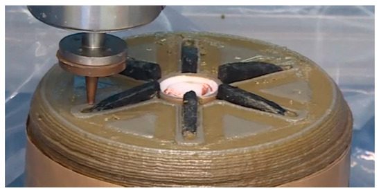
Figure 4.
Printing status at the fin.
2.6. Experiment of Scaled-Down Motor
In order to verify the feasibility and practical effectiveness of the ultra-low-pressure ratio technology, a special motor scheme for scaling verification was designed. The motor in the experiment is mainly composed of combustion chamber, ignition top cover, nozzle, etc. The combustion chamber is composed of an adiabatic shell and a coated grain. The 3D model diagram and structure schematic of the motor are shown in Figure 5 and Figure 6, respectively.
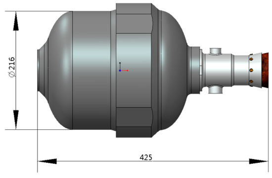
Figure 5.
Motor structure.
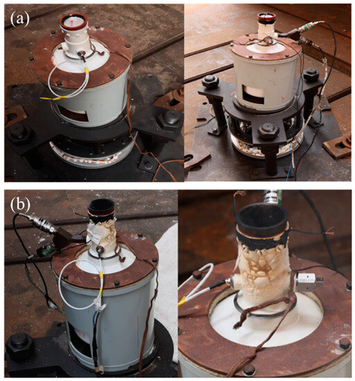
Figure 6.
Photos of the propellant before and after the experiment: (a) before experiment; (b) after experiment.
In the experiment, the motor worked normally, the structure was complete, and the experimental performance met the design requirements. The motor test was a complete success, and the comprehensive performance of the motor was preliminarily evaluated.
3. Results and Discussions
3.1. Structural Integrity of 3D-Printed Grains
Table 1 displays the structural dimensions of the grain after molded, while Figure 7 illustrates the results of the 4MeV industrial CT inspection of the grain. From the figure, the internal grain structure of the printed grain is complete and clear, and it is consistent with the designed grain model. There is no obvious defect inside the coated grain, and the complex internal pore structure is realized.

Table 1.
Main experimental performance data of the grain.
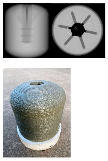
Figure 7.
Non-destructive experiment of coated grain.
3.2. Mechanical Properties of Grains
The Universal Testing Machine was used to measure the mechanical performance parameters of solid propellant. The printed rectangular solid propellant specimen was stretched unidirectionally, and its tensile strength and fracture elongation were measured at 20 °C, 70 °C, and −40 °C. The experimental results are shown in Table 2 and Figure 8. Table 2 reveals that, compared with conventional HTPB solid grains, 3D-printed solid grains exhibit some discrepancy in tensile strength. However, the rate of elongation remains comparable to that of conventional grains.
Table 2.
Mechanical property experiment results of 3D-printed solid propellant.
Figure 8.
Uniaxial tensile experiment results of propellant specimens at 20 °C, 70 °C, −40 °C. (a) Results at 20 °C; (b) results at 70 °C; (c) results at −40 °C.
3.3. Combustion Properties of the Grains
Ao [21] firstly proposed a full-cycle testing technology for propellant combustion, which has been adapted to solid propellant detection for applications ranging from aluminum ignition to combustion products. By using their laser ignition test setup, Figure 9a,b shows the typical combustion processes of 3D-printed propellant and the contrast group propellant. It can be observed that under the same exposure time, the brightness of the contrast group propellant during combustion is greater than that of the 3D-printed propellant. Furthermore, the coral-like propellant skeleton observed during the combustion process of the 3D-printed propellant has fewer layers compared to the contrast group propellant, indicating that the components of the 3D-printed propellant may be more uniformly mixed. Figure 9c compares the combustion intensities of the 3D-printed propellant and the contrast group propellant. It can be concluded that the combustion intensity of the contrast group propellant is greater than that of the 3D-printed propellant, which is consistent with the intensity conclusions obtained from the combustion images.

Figure 9.
(a) Typical combustion process of 3D-printed propellant; (b) typical process of propellant combustion of the propellant in contrast group; (c) comparison of combustion intensity between 3D-printed propellant and propellant in contrast group; (d) comparison of ignition delay time and burning rate between 3D-printed propellant and propellant in contrast group.
The variation of spectral intensity at a wavelength of 486 nm is considered as the change in combustion intensity of the specimens. After normalizing the experimental data at a wavelength of 586 nm, the ignition delay time is defined as the time difference between the start of timing and the first occurrence of an intensity reaching 0.1 (10 percent of the maximum intensity). The linear burning rate of the solid composite propellant was determined by processing video recordings, which were taken during the combustion experiments. Image processing software (Image J 1.52a) was used to extract the distance by which the propellant surface moved. And this distance was then divided by the elapsed time to obtain the burning rate. Figure 9d presents a comparison of the ignition delay time and burning rate between the 3D-printed propellant and the propellants in the contrast group. The ignition delay time of the 3D-printed propellants is approximately 13 ms, which is shorter than the propellant in contrast group (47 ms). However, the burning rate of the 3D-printed propellant is 1.077 mm/s, which is lower than that of the propellant in the contrast group (1.201 mm/s). Nevertheless, the error bars for the ignition delay time and burning rate of the 3D-printed propellant are both smaller than those of the propellant in contrast group. It indicates that the components of the 3D-printed propellant are more uniform and the experimental data have smaller errors.
3.4. Experiment of Scaled-Down Motor
The main performance data measured by the scaled-down motor are shown in Table 3, the internal ballistic performance curve is shown in Figure 10, and the motor experiment recording is shown in Figure 11. According to the measured pressure-time curve of the motor experiment, the internal pressure of the motor is stable during the working process, and the pressure ratio of the two motors is less than 1.03.
Table 3.
Performance data in motor experiment.
Figure 10.
Motor internal ballistic performance results.

Figure 11.
Solid rocket motor experiment recording: (a) 0.1 s; (b) 1 s; (c) 5 s; (d) 9 s.
3.5. Effectiveness Analysis of Ultra-Low-Pressure Ratio
Comparison of the technical effectiveness of ultra-low-pressure ratio motor is shown in Table 4, from which it can be seen that the measured pressure ratio of the prototype is less than 1.03, which is much lower than the pressure ratio of the contrast motor (1.28). It provides a possibility for the weight reduction of bearing structural parts such as the motor housing. The following also takes the contrast motor as an example. After comprehensive analysis of the comparison between the two, the ultra-low-pressure ratio motor technology can achieve a reduction of 1.25 Mpa in maximum pressure and a reduction of 35 kg in structural mass under the constraints of the existing technical indicators, with reductions of approximately 19.5% and 11.5%, respectively.
Table 4.
Comparison table of technical effectiveness of ultra-low-pressure ratio motor.
4. Concluding Discussion
In this paper, based on 3D printing technology, the molding of the solid propellant with complex structure was completed, and the feasibility of ultra-low-pressure ratio technology was preliminarily verified. In addition, the realization of the form and effect of ultra-low-pressure ratio technology was analyzed. The main conclusions are as follows:
(1) This paper puts forward ultra-low-pressure ratio technology, which can improve the performance of the motor. Taking a motor as an example, the maximum working pressure can be reduced by about 19.5%, which directly reduces the bearing load of the shell and reduces the mass of the pressure parts such as the shell.
(2) For the ultra-low-pressure ratio technology, the 3D printing molding of the grain with a complex structure was completed, and the structure and quality of the specimen met the requirements. The feasibility of the ultra-low-pressure ratio technology was verified through the experiment, and the mass of the motor structure could be reduced by 11.5%.
(3) The work of this paper belongs to the exploration and research on the application of 3D technology in the field of solid propellants. In the future, we will continue to carry out in-depth research on 3D-printed solid propellant technology, deeply explore the comprehensive performance of 3D-printed solid propellants, and explore their innovative applications in solid rocket motors.
Author Contributions
Conceptualization, S.S. and M.T.; software, J.S.; data curation, J.W.; writing—original draft preparation, S.S.; writing—review and editing, Q.R. All authors have read and agreed to the published version of the manuscript.
Funding
This research was funded by the National Key Research and Development Program (2022YFB4603100).
Data Availability Statement
Data is unavailable due to privacy.
Conflicts of Interest
The authors declare no conflict of interest.
References
- Lu, B.; Li, D. Development of the Additive Manufacturing (3D Printing) Technology. Mach. Build. Autom. 2013, 42, 1–4. [Google Scholar]
- Li, D.; Liu, J.; Wang, Y.; Wang, Y.; Wang, S. 4D Printing-Additive Manufacturing Technology of Smart Materials. Mech. Electr. Eng. Technol. 2014, 43, 1–9. [Google Scholar]
- Yang, Y. Analysis of Classifications and Characteristic of Additive Manufacturing (3D Print). Adv. Aeronaut. Sci. Mot. 2019, 10, 309–318. [Google Scholar]
- Chandru, R.A.; Balasubramanian, N.; Oommen, C.; Raghunandan, B.N. Additive manufacturing of solid rocket propellant grains. J. Propuls. Power 2018, 34, 1090–1093. [Google Scholar] [CrossRef]
- Xiao, L.; Hao, G.; Guo, R.; Ke, X.; Zhang, G. Research Status and Prospect of Additive Manufacturing Technology for Energetic Materials. Chin. J. Explos. Propellants 2022, 45, 133–153. [Google Scholar]
- Jiang, Y.; Zhao, F.; Li, H.; Zhang, M.; Jiang, Z. Direct Ink Writing Technology for Additive Manufacturing and Its Research Progress in Energetic Materials. Chin. J. Explos. Propellants 2022, 45, 1–19. [Google Scholar]
- Gibson, I.; Rosen, D.; Stucker, B. Additive Manufacturing Technologies; Springer: New York, NY, USA, 2015. [Google Scholar]
- Hernandez, R.N.; Singh, H.; Messimer, S.L.; Patterson, A.E. Design and Performance of Modular 3-D Printed Solid-propellant Rocket Airframes. Aerospace 2017, 4, 17. [Google Scholar] [CrossRef]
- Nguyen, C.; Thomas, J.C. Performance of Additively Manufactured Fuels for Hybrid Rockets. Aerospace 2023, 10, 500. [Google Scholar] [CrossRef]
- Grefen, B.; Becker, J.; Linke, S.; Stoll, E. Design, Production and Evaluation of 3D-printed Mold Geometries for A Hybrid Rocket Motor. Aerospace 2021, 8, 220. [Google Scholar] [CrossRef]
- Wu, F.; Liu, L.; Xu, Y.; Qiu, M.; Wang, B. The Development of 3D Printing Technology in the Field of Foreign Aerospace. Aerodyn. Missile J. 2013, 12, 10–15. [Google Scholar]
- Qi, M.; Li, X.; Hu, X.; Gou, G.; Huang, Q.; Wang, Z. The Development Status and Trend of Additive Manufacturing Technology in Foreign Defense Field. Def. Manuf. Technol. 2013, 5, 12–16. [Google Scholar]
- Fereiduni, E.; Ghasemi, A.; Elbestawi, M. Selective Laser Melting of Aluminum and Titanium Matrix Composites: Recent Progress and Potential Applications in the Aerospace Industry. Aerospace 2020, 7, 77. [Google Scholar] [CrossRef]
- Bou, F.; Hou, X. Solid Rocket Motor Design; China Aerospace Press: Beijing, China, 2016. [Google Scholar]
- Ruan, C. Critical Techniques in Development of Large-size Solid Rocket Motors. J. Solid Rocket. Technol. 2005, 28, 23–28. [Google Scholar]
- Yang, J.; Chen, R.; Zhao, X. Integral Optimizaiton Design for Tactical Rocket and It’s SRM by Unilizing the Synthesis of Internal Ballistics and Trajectory. J. Astronaut. 1999, 1, 22–28. [Google Scholar]
- Krishnan, S.; Bose, T.K. Design of Multi-Propellant Star Grains for Solid Propellant Rockets. Def. Sci. J. 1980, 30, 21–30. [Google Scholar] [CrossRef]
- Zeng, M. Technology Methods to Improve Solid Rocket Motor Performances. J. Propuls. Technol. 1994, 4, 40–46. [Google Scholar]
- Yang, J.; Rong, H. Design Optimization of Solid Motor Grains. J. Propuls. Technol. 1997, 18, 98–102. [Google Scholar]
- Mejia, G.; Jachura, R.; Gomes, S.R.; Rocco, L.; Rocco, J.A.; Iha, K. Solid Rocket Motor Burn Simulation Considering Complex 3D Propellant Grain Geometries. In Proceedings of the 52nd AIAA/SAE/ASEE Joint Propulsion Conference, Salt Lake City, UT, USA, 25–27 July 2016; p. 5098. [Google Scholar]
- Ao, W.; Wen, Z.; Liu, L.; Wang, Y.; Zhang, Y.; Liu, P.; Qin, Z.; Li, L.K. Combustion and agglomeration characteristics of aluminized propellants containing Al/CuO/PVDF metastable intermolecular composite: A highly adjustable functional catalyst. Combust. Flame 2022, 241, 112110. [Google Scholar] [CrossRef]

Disclaimer/Publisher’s Note: The statements, opinions and data contained in all publications are solely those of the individual author(s) and contributor(s) and not of MDPI and/or the editor(s). MDPI and/or the editor(s) disclaim responsibility for any injury to people or property resulting from any ideas, methods, instructions or products referred to in the content. |
© 2023 by the authors. Licensee MDPI, Basel, Switzerland. This article is an open access article distributed under the terms and conditions of the Creative Commons Attribution (CC BY) license (https://creativecommons.org/licenses/by/4.0/).