
A Study on Influence of Flapping Dynamic Characteristics on Vibration Control of Active Rotor with Trailing-Edge Flaps

Abstract
:1. Introduction
2. Aeroelastic Model
2.1. Model Establishment
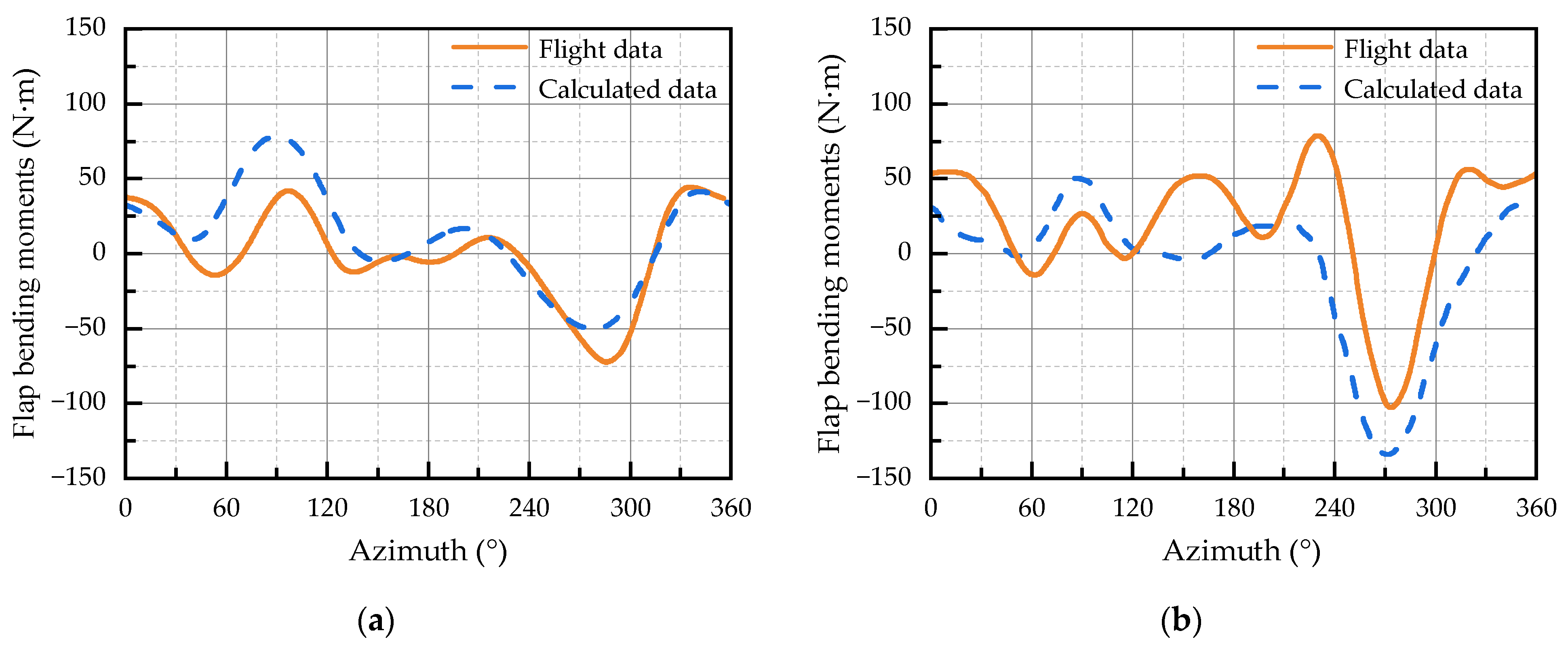
2.2. Model Validation
3. Adjustment Method of Flap Dynamics
4. Simulation Results
5. Conclusions
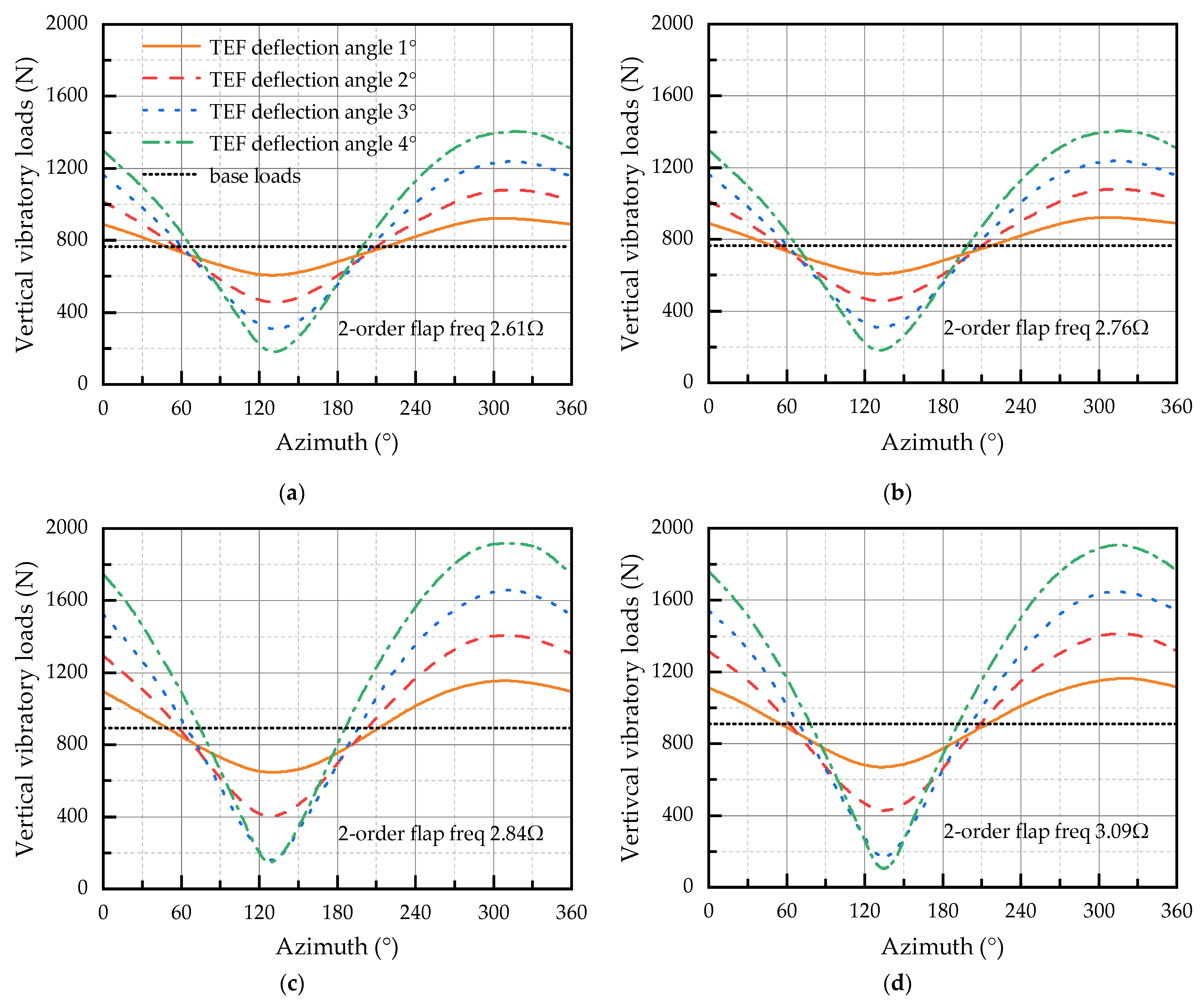
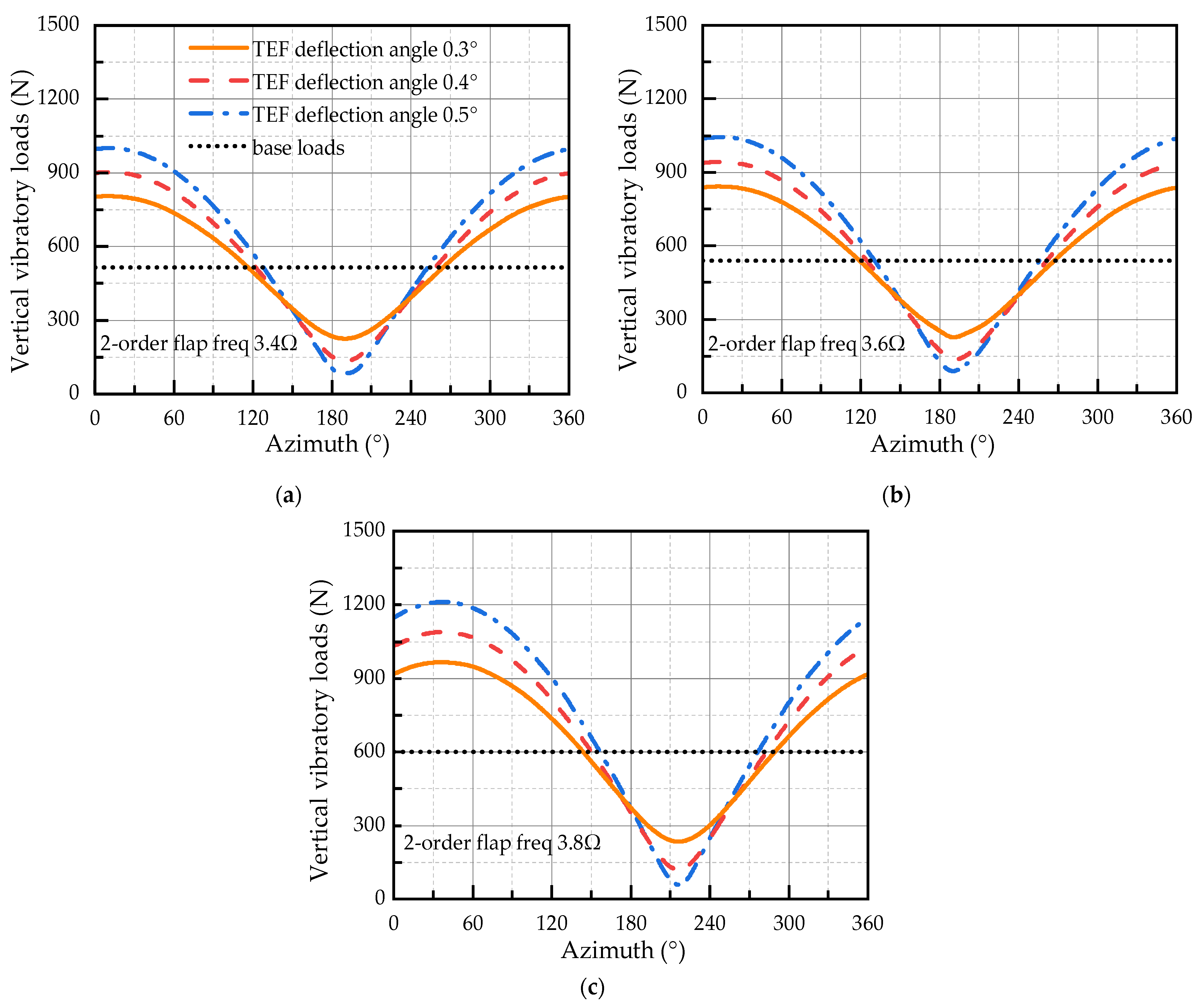
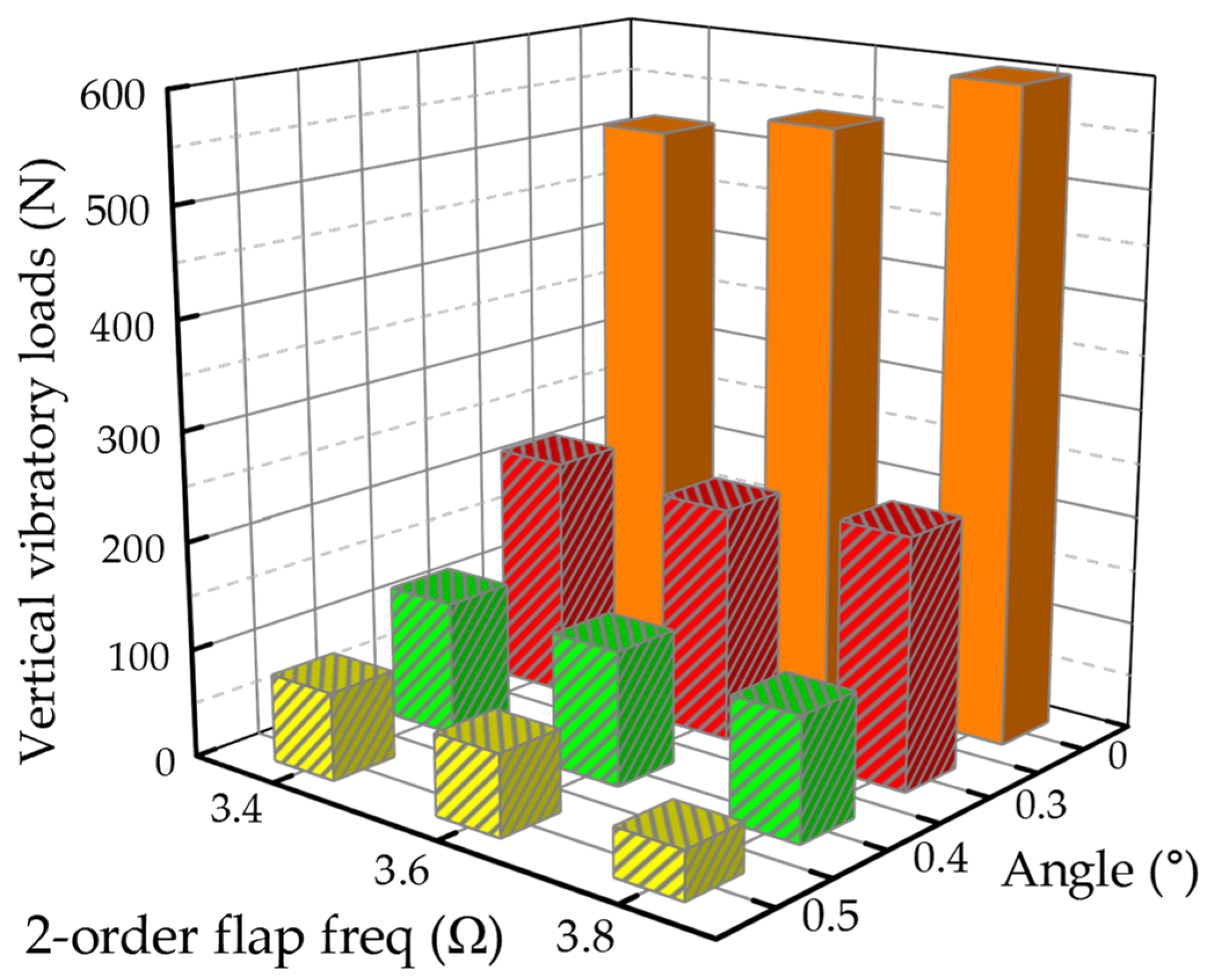
- For a rotor system with blades, different flap deflection frequencies produce different vibration reduction effects on the rotor for the same deflection angle. If the second-order flapping natural frequency of the blade is tuned close to the passage frequency, the dynamic magnification factor is enlarged, and the base vibration load level is enhanced.
- If the deflection frequency of the TEF control inputs is close to the second-order flapping natural frequency of the blade, the control effect of the rotor vertical vibratory loads can be improved. The configuration of dynamic characteristics for the blade second-order flapping mode can be fully utilized to enhance the effectiveness of the active rotor and to obtain lower vertical vibratory loads of the hub.
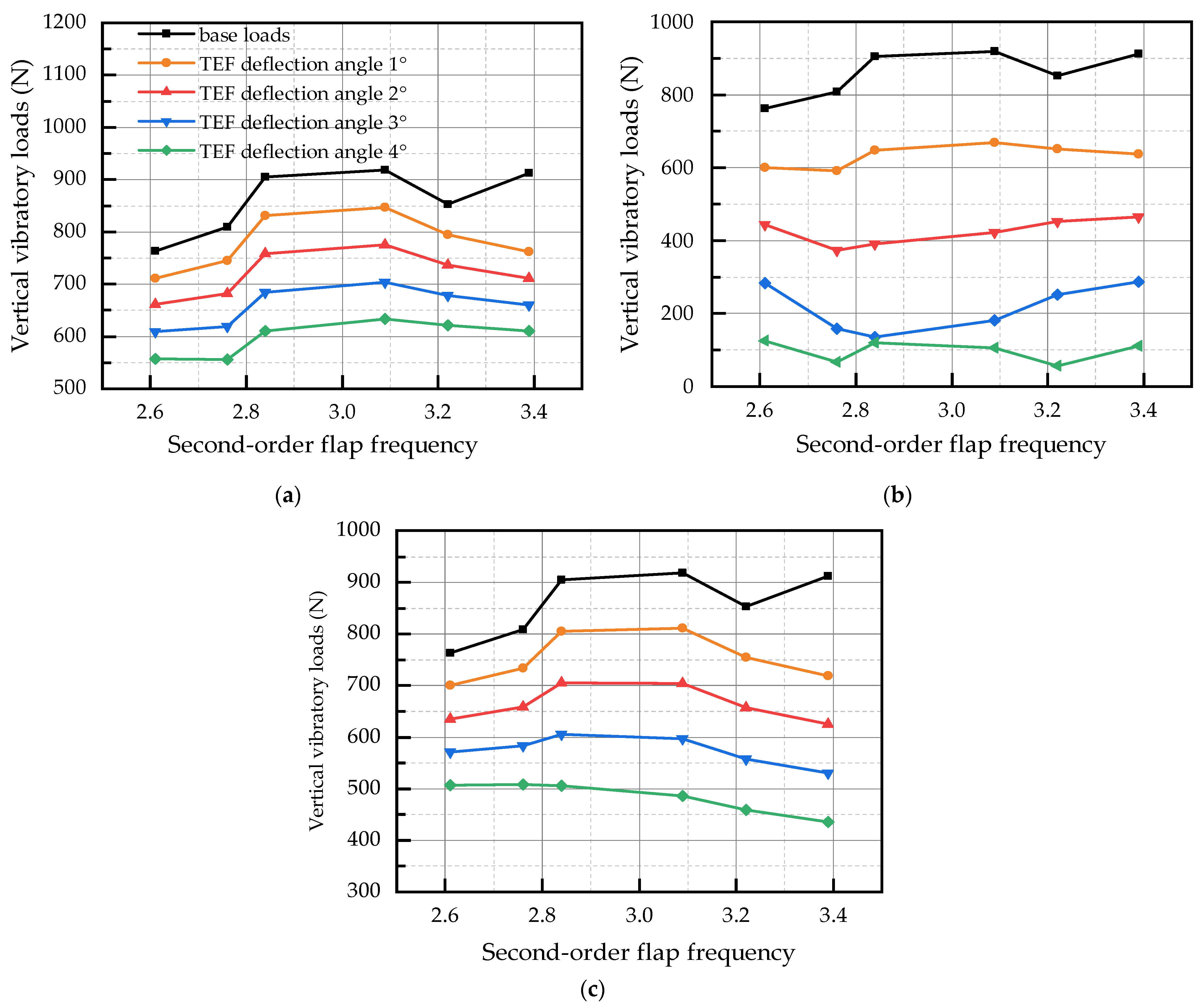
- For the three-bladed and four-bladed rotor, if the second-order flapping natural frequency is configured at 2.6–2.7 Ω and 3.6–3.7 Ω, respectively, a balance between base vibration levels and vibration control effects of the active rotor can be achieved. For the three-bladed rotor, if the second-order flapping natural frequency is configured at 3.2–3.4 Ω, it is possible to achieve a compromise between lower controlled loads and vibration control effects.
Author Contributions
Funding
Data Availability Statement
Conflicts of Interest
References
- Robert, B. Helicopter Rotor Blade Design for Minimum Vibration; NASA Technical Report, 74-A-2; United Technologies Research Center: East Hartford, CT, USA, 1984. [Google Scholar]
- Breitbach, E.; Buter, A. The main sources of helicopter vibration and noise emissions and adaptive concepts to reduce them. J. Struct. Control 1996, 3, 21–32. [Google Scholar] [CrossRef]
- Yong, C.; Zimcik, D.G.; Wickramasinghe, V.K.; Nitzsche, F. Development of the smart spring for active vibration control of helicopter blades. J. Intel. Mat. Syst. Str. 2004, 15, 37–47. [Google Scholar] [CrossRef]
- Pearson, J.T.; Goodall, R.M.; Lyndon, I. Active control of helicopter vibration. Comput. Control Eng. 1994, 5, 277–284. [Google Scholar] [CrossRef]
- Yang, R.G.; Gao, Y.D.; Wang, H.M.; Ni, X.P. Fuzzy neural network PID control used in Individual blade control. Aerospace 2023, 10, 623. [Google Scholar] [CrossRef]
- Wilbur, M.L.; Mirick, P.H.; Yeager, W.T.; Langston, C.W.; Cesnik, C.E.S.; Shin, S. Vibratory loads reduction testing of the NASA/ARMY/MIT active twist rotor. J. Am. Helicopter Soc. 2002, 47, 123–133. [Google Scholar] [CrossRef]
- Jia, K.; Scofield, T.; Wei, M.; Bhattacharya, S. Vorticity transfer in a leading-edge vortex due to controlled spanwise bending. Phys. Rev. Fluids 2021, 6, 024703. [Google Scholar] [CrossRef]
- Joshi, K.; Bhattacharya, S. The unsteady force response of an accelerating flat plate with controlled spanwise bending. J. Fluid Mech. 2022, 933, A56. [Google Scholar] [CrossRef]
- Soto, C.; Bhattacharya, S. The effect of dynamic twisting on the flow field and the unsteady forces of a heaving flat plate. Bioinspir. Biomim. 2023, 18, 026010. [Google Scholar] [CrossRef]
- Friedmann, P.P. On-blade control of rotor vibration, noise, and performance: Just around the corner? J. Am. Helicopter Soc. 2014, 59, 1–37. [Google Scholar] [CrossRef]
- Ma, J.C.; Lu, Y.; Su, T.Y.; Guan, S.J. Experimental research of active vibration and noise control of electrically controlled rotor. Chin. J. Aeronaut. 2021, 34, 106–118. [Google Scholar] [CrossRef]
- Padthe, A.K.; Friedmann, P.P. Simultaneous blade–vortex interaction noise and vibration reduction in rotorcraft using microflaps, including the effect of actuator saturation. J. Am. Helicopter Soc. 2015, 60, 1–16. [Google Scholar] [CrossRef]
- Chia, M.H.; Padthe, A.K.; Duraisamy, K.; Friedmann, P.P. An effective approach for the simulation and on-blade control of helicopter noise and the impact on vibration. J. Am. Helicopter Soc. 2017, 62, 1–15. [Google Scholar] [CrossRef]
- Straub, F.K.; Kennedy, D.K.; Stemple, A.D.; Anand, V.R.; Bircgette, T.S. Development and whirl tower test of the SMART active flap rotor. In Proceedings of the SPIE’s Intl Symposium on Smart Structures and Materials, San Diego, CA, USA, 29 July 2004; pp. 14–18. [Google Scholar] [CrossRef]
- Straub, F.K.; Anand, V.R.; Bircgette, T.S.; Benton, H.L. SMART rotor development and wind tunnel test. In Proceedings of the 35th European Rotorcraft Forum, Hamburg, Germany, 22–25 September 2009. [Google Scholar]
- Roth, D.; Enenkl, B.; Dieterich, O. Active rotor control by flaps for vibration reduction—Full scale demonstrator and first flight test results. In Proceedings of the 32nd European Rotorcraft Forum, Maastricht, The Netherlands, 12–14 September 2006. [Google Scholar]
- Rabourdin, A.; Maurice, J.B.; Dieterich, O.; Konstanzer, P. Blue Pulse active rotor control at Airbus Helicopters—New EC145 demonstrator and flight test results. In Proceedings of the 70th Annual Forum of the American Helicopter Society, Montreal, QC, Canada, 20–22 May 2014. [Google Scholar]
- Dieterich, O.; Rabourdin, A.; Maurice, J.B.; Konstanzer, P. Blue pulse: Active rotor control by trailing edge flaps at Airbus helicopters. In Proceedings of the 41st European Rotorcraft Forum, Munich, Germany, 1–4 September 2015. [Google Scholar]
- Zhou, J.L.; Dong, L.H.; Yang, W.D. Experimental study on transfer functions of an active rotor under different flight conditions. Chin. J. Aeronaut. 2022, 35, 107–120. [Google Scholar] [CrossRef]
- Van Wingerden, J.W.; Hulskamp, A.; Blarlas, T.; Houtzager, I.; Bersee, H.; Van Kuik, G.; Verhaegen, M. Two-Degree-of-Freedom Active Vibration Control of a Prototyped “Smart” Rotor. IEEE Trans. Control Syst. Technol. 2011, 2, 284–296. [Google Scholar] [CrossRef]
- Castaignet, D.; Barlas, T.; Buhl, T.; Poulsen, N.K.; Wedel-Heinen, J.J.; Olesen, N.A.; Bak, C.; Kim, T. Full-scale test of trailing edge flaps on a Vestas V27 wind turbine: Active load reduction and system identification. Wind Energ. 2014, 17, 549–564. [Google Scholar] [CrossRef]
- Ganguli, R. Optimum design of a helicopter rotor for low vibration using aeroelastic analysis and response surface methods. J. Sound Vib. 2002, 258, 327–344. [Google Scholar] [CrossRef]
- Jain, R.; Yeo, H. Effects of torsion frequencies on rotor performance and structural loads with trailing edge flap. Smart Mater. Struct. 2012, 21, 085026. [Google Scholar] [CrossRef]
- Shen, J.; Chopra, I. A parametric design study for a swashplateless helicopter rotor with trailing-edge flaps. J. Am. Helicopter Soc. 2004, 49, 43–53. [Google Scholar] [CrossRef]
- Ravichandran, K.; Chopra, I. Trailing-edge flaps for rotor performance enhancement and vibration reduction. J. Am. Helicopter Soc. 2013, 58, 022006. [Google Scholar] [CrossRef]
- Johnson, W. Rotorcraft Aeromechanics, 1st ed.; Cambridge University Press: New York, NY, USA, 2013; pp. 710–722. [Google Scholar]
- Chen, K. Research on Optimization Dynamic Design of Composite Rotor Blade for Helicopter Vibration Reduction. Ph.D. Thesis, Nanjing University of Aeronautics and Astronautics, Nanjing, China, 2014. [Google Scholar]
- Liu, S.M. Research on Vibratory Load Control of Smart Rotor with Trailing Edge Flaps. Ph.D. Thesis, Nanjing University of Aeronautics and Astronautics, Nanjing, China, 2016. [Google Scholar]
- Wu, J. Research on Helicopter Rotor Aeroelastic Vibratory Loads. Ph.D. Thesis, Nanjing University of Aeronautics and Astronautics, Nanjing, China, 2013. [Google Scholar]
- Dodic, M.; Krstic, B.; Rasuo, B.; Dinulovic, M.; Bengin, A. Numerical analysis of Glauert inflow for single-rotor helicopter in steady-level flight below stall-flutter limit. Aerospace 2023, 10, 238. [Google Scholar] [CrossRef]
- Pitt, D.M.; Peters, D.A. Theoretical prediction of dynamic-inflow derivatives. In Proceedings of the Sixth European Rotorcraft and Powered Lift Aircraft Forum, Bristol, UK, 16–19 September 1980. [Google Scholar]
- Peters, D.A. How dynamic inflow survives in the competitive world of rotorcraft aerodynamics. J. Am. Helicopter Soc. 2008, 54, 011001. [Google Scholar] [CrossRef]
- Hassan, A. Predicted Aerodynamic Characteristics of a NACA 0015 Airfoil Having a 25% Integral-Type Trailing Edge Flap; NASA Technical Report; Langley Research Center: Hampton, VA, USA, 1999.
- Navarrete, J. Construction of Airfoil Performance Tables by the Fusion of Experimental and Numerical Data. Master’s Thesis, Rice University, Houston, TX, USA, 2004. [Google Scholar]
- Stanko, J. Automated Design and Evaluation of Airfoils for Rotorcraft Applications. Master’s Thesis, The Pennsylvania State University, State College, PA, USA, 2017. [Google Scholar]
- Theodorsen, T.; Garrick, I.E. Nonstationary Flow About a Wing-Aileron-Tab Combination Including Aerodynamic Balance; NACA Technical Report, 736; Langley Aeronautical Lab: Langley Field, VA, USA, 1942. [Google Scholar]
- Theodorsen, T. General Theory of Aerodynamic Instability and the Mechanism of Flutter; NACA Technical Report, 496; NASA Ames Research Center: California, CA, USA, 1979.
- Leishman, J.G. Unsteady lift of a flapped airfoil by indicial concepts. J. Aircr. 1994, 31, 288–297. [Google Scholar] [CrossRef]
- Bielawa, R.L. Blade stress calculations-mode deflection vs. force integration. In American Helicopter Society Symposium on Rotor Technology; United Technologies Research Center: East Hartford, CT, USA, 1976. [Google Scholar]
- Heffernan, R.M.; Gaubert, M. Structural and Aerodynamics Loads and Performance Measurements of an SA349/2 Helicopter with an Advanced Geometry Rotor; NASA Technical Memorandum, 88370; Ames Research Center: California, CA, USA, 1986.
- Bir, G.; Chopra, I. University of Maryland Advanced Rotorcraft Code Theory Manual; Center for Rotorcraft Education and Research University of Maryland: College Park, MD, USA, 1994. [Google Scholar]
- Yang, R.G.; Gao, Y.D.; Wang, H.M.; Ni, X.P. Reducing helicopter vibration loads by individual blade control with genetic algorithm. Machines 2022, 10, 479. [Google Scholar] [CrossRef]


| Parameters | Value |
|---|---|
| Rotor radius | 5.25 |
| Number of blades | 3 |
| Chord length | 0.35 |
| Operating speed | 387 |
| Pre-twisted angle | −4.9 |
| Rotor solidity | 0.06366 |
| Airfoil | OA209 |
| Natural Frequency | Calculation (Ω) | CAMRAD [40] (Ω) | Error (%) |
|---|---|---|---|
| First flap | 1.0478 | 1.02 | 2.725 |
| Second flap | 2.7788 | 2.78 | 0.043 |
| Third flap | 4.7039 | 4.84 | 2.812 |
| First lead-lag | 0.5878 | 0.59 | 0.373 |
| Second lead-lag | 5.1960 | 5.23 | 0.650 |
| First torsion | 4.2083 | 4.16 | 1.161 |
| Blade Types | Second-Order Flapping Frequency/Ω | Base Vertical Vibratory Loads/N |
|---|---|---|
| Type I | 2.61 | 762.8 |
| Type II | 2.76 | 808.8 |
| Type III | 2.84 | 905.1 |
| Type IV | 3.09 | 918.8 |
| Type V | 3.22 | 852.8 |
| Type VI | 3.39 | 812.5 |
Disclaimer/Publisher’s Note: The statements, opinions and data contained in all publications are solely those of the individual author(s) and contributor(s) and not of MDPI and/or the editor(s). MDPI and/or the editor(s) disclaim responsibility for any injury to people or property resulting from any ideas, methods, instructions or products referred to in the content. |
© 2023 by the authors. Licensee MDPI, Basel, Switzerland. This article is an open access article distributed under the terms and conditions of the Creative Commons Attribution (CC BY) license (https://creativecommons.org/licenses/by/4.0/).
Share and Cite
Gu, X.; Dong, L.; Li, T.; Yang, W. A Study on Influence of Flapping Dynamic Characteristics on Vibration Control of Active Rotor with Trailing-Edge Flaps. Aerospace 2023, 10, 776. https://doi.org/10.3390/aerospace10090776
Gu X, Dong L, Li T, Yang W. A Study on Influence of Flapping Dynamic Characteristics on Vibration Control of Active Rotor with Trailing-Edge Flaps. Aerospace. 2023; 10(9):776. https://doi.org/10.3390/aerospace10090776
Chicago/Turabian StyleGu, Xiancheng, Linghua Dong, Tong Li, and Weidong Yang. 2023. "A Study on Influence of Flapping Dynamic Characteristics on Vibration Control of Active Rotor with Trailing-Edge Flaps" Aerospace 10, no. 9: 776. https://doi.org/10.3390/aerospace10090776
APA StyleGu, X., Dong, L., Li, T., & Yang, W. (2023). A Study on Influence of Flapping Dynamic Characteristics on Vibration Control of Active Rotor with Trailing-Edge Flaps. Aerospace, 10(9), 776. https://doi.org/10.3390/aerospace10090776