Abstract
For civil high-speed rotorcraft designed to operate at specific cruising altitudes, this study proposes nine structural design schemes for pressurized cabins. These schemes integrate commonly used materials and processing technologies in the aviation industry with advanced PRSEUS (Pultruded Rod Stitched Efficient Unitized Structure) technology. An analysis of the structural composition reveals that frames constitute 8–19% of the total structural weight, while stringers and beams make up 15–50%, and skins account for 11–25%, with thicknesses ranging from 1.0 mm to 2.0 mm. The separating interface of the pressurized cabin contributes 4–29% of the total structural weight. The weight distribution of each component in the pressurized cabin structure varies significantly depending on the chosen materials and processing technologies. Utilizing the Analytic Hierarchy Process (AHP), along with Gray Relational Analysis (GRA) and Dempster–Shafer (D-S) evidence theory, this study compares the simulation results of the nine schemes across multiple dimensions. The findings indicate that the configuration combining 7075 aluminum alloy and T300 composite material has the greatest advantages in terms of the high structural reliability of the configuration, light weight, mature processing technology, and low production cost. This comprehensive evaluation method quantitatively analyzes the factors influencing the structural configuration design of the pressurized cabin for civil high-speed rotorcraft, offering a valuable reference for the design of similar structures in related fields.
1. Introduction
The development of helicopters commenced in the early 20th century. With advancements in aviation technology and breakthroughs in critical technologies, the international community is accelerating the progress and validation of new high-speed rotorcraft programs [1,2,3]. High-speed rotorcraft combine the benefits of both rotorcraft and fixed-wing aircraft, offering efficient mission effectiveness and quick response capabilities. Their potential in commercial transport has been recognized by developed nations such as the United States and countries in Europe, presenting vast market prospects [4].
In recent years, international research on high-speed rotorcraft has increased, significantly enhancing their cruising altitude and speed. In the civilian market, these advancements pose challenges for existing non-pressurized cockpit designs, which are inadequate for ensuring airworthiness at higher altitudes or passenger comfort. Consequently, the early-stage development of pressurized cabin configurations is crucial for overcoming these technological barriers and has significant implications for engineering applications.
Currently, a mature design and production system for these technologies has yet to be established, and research remains limited. Although the U.S.-based Sikorsky company (Statford, CT, USA) has developed helicopters featuring pressurized cabins, in-depth research in this area is necessary. The expansion of design concepts, technical methodologies, and practical application cases is limited, making the detailed study of pressurized cabin designs a pivotal topic for future helicopter design.
In the aerospace field, the continuous refinement of machining processes and the in-depth exploration of new configurations provide a variety of ideas for the configuration design of pressurized cabins in civil high-speed rotorcraft [5,6]. At the preliminary design stage, various loading conditions on pressurized cabins are accurately simulated using simulation software. This includes data on stress, strain, and displacement. Additionally, scientific evaluation index systems are established to assess the strengths and weaknesses of different designs from multiple dimensions [7,8,9,10,11,12,13,14].
This paper presents nine structural configuration designs of pressurized compartments for civil high-speed rotorcraft operation scenarios. The cutting-edge PRSEUS structural scheme in the current aviation field is introduced, and the configuration schemes mostly used in the current aviation field are proposed to provide multiple structural-type references for the subsequent structural design of a helicopter’s pressurized compartment. Through simulation and analysis, as well as the innovative combination of AHP, GRA, and D-S evidence theories, a new assessment method is introduced for structural scheme evaluation, and the influencing factors of the structural configuration design of the pressurized compartment of a civil high-speed rotorcraft are quantitatively analyzed, which provides valuable references for the evaluation of similar schemes in related fields.
2. Introduction to the Structural Configuration of the Pressurized Cabin of the Rotorcraft
2.1. Research Objective
This paper undertakes the preliminary design of pressurized cabin structural configurations, marking the initial phase of structural design. The objective is to conduct a multi-dimensional comprehensive assessment of various structural configuration options and establish a comprehensive evaluation method. This serves to guide subsequent selections and optimizations of pressurized cabin structures.
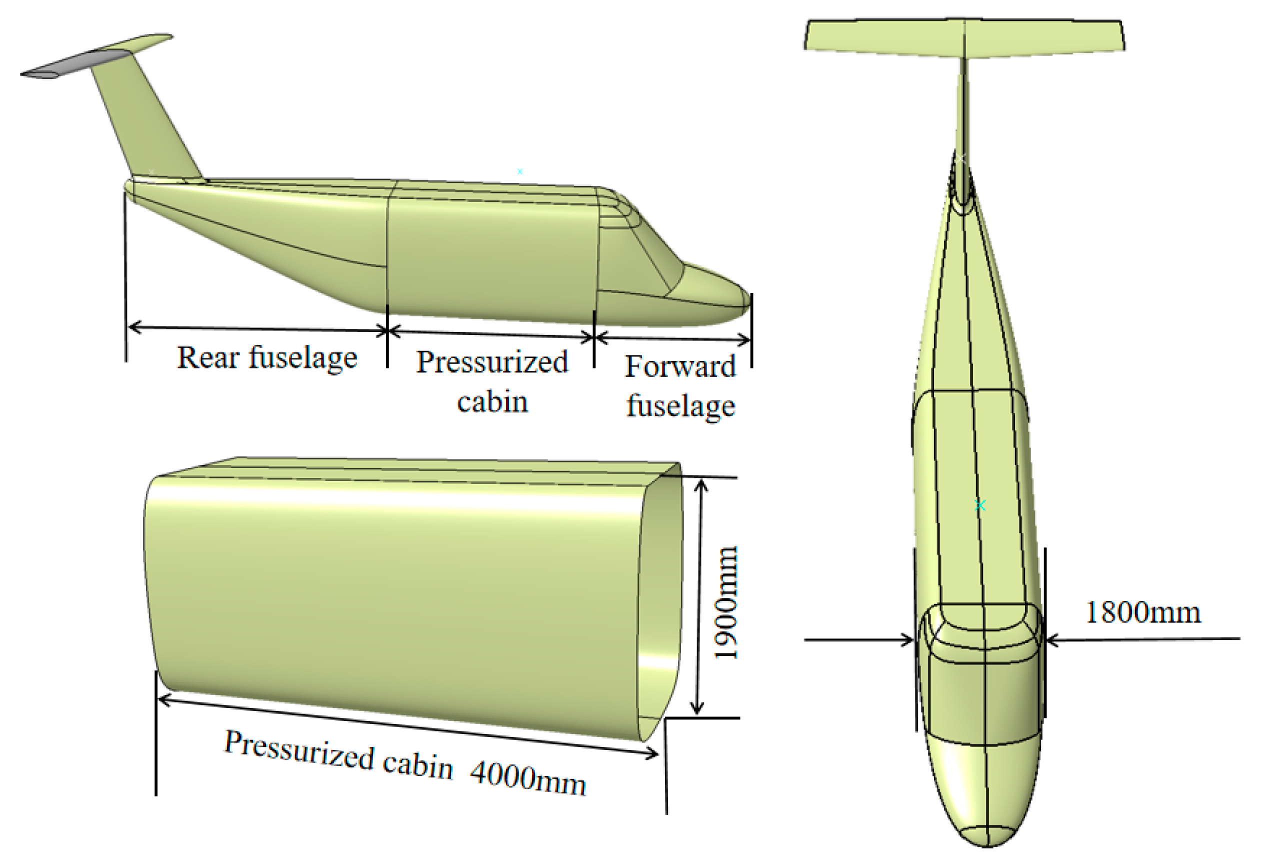
The study uses a nine-seat civilian high-speed rotorcraft as a case study for the design of the pressurized cabin structure. The aerodynamic shape of the rotorcraft is depicted in Figure 1. The fuselage is simplified into a rectangular box section with a uniform cross-section. The preliminary structural configuration is designed without considering aerodynamic loads or bending loads transferred from other parts of the fuselage and wings. It focuses solely on the pressurized loads of the cabin, floor loads, and the weight of the structure itself.
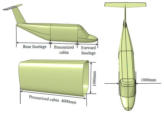
Figure 1.
Civilian high-speed rotorcraft aerodynamic profile.
2.2. Structural Program
In the design process, this paper primarily addresses four types of damage scenarios: damage to the skin or stringers (or spars), skin instability, panel instability, and overall instability.
The pressurized cabin of civil high-speed rotorcraft comprises skin, stringers, frames, reinforcing frames, and flooring, which are subjected to pressurized loads. Through the strategic placement of spacer frames, reinforcing frames, and stringers, the pressurized load is effectively distributed, ensuring that the overall structure meets the design requirements.
2.2.1. Structural Configuration Design of the Pressurized Cabin
Research has demonstrated that thin-walled stringer structures offer the benefits of lightweight properties, high strength, high structural efficiency, ease of fabrication, and maintenance advantages compared to thick-skinned structures [15]. Consequently, the pressurized cabin configuration selected is a thin-walled stringer structure, informed by prior experience.
The thin-walled stringer fuselage represents a structural form featuring multiple force transfer paths and high damage tolerance, capable of redistributing loads locally without causing comprehensive damage to the fuselage structure. The skin and stringers (or spars) create a reinforced box segment structure. Frames are strategically placed within the box segments to prevent buckling and maintain the sectional shape of the fuselage.
The configuration parameters refer to the known DC-10, Airbus 319, Boeing 777, and Boeing 707 civil airliners’ pressurized cabins for the preliminary design of the long truss, the height of the spacer frame, the thickness, and so on, to establish a preliminary pressurized cabin configuration through simulation, to analyze the strength and stiffness of the structure in the multi-loading conditions, and to adjust the configuration parameters so that they conform to the design of a certain type of helicopter pressurized cabin under the study of the design requirements.
During the design phase, considerations for potential modifications include the reservation of positions and reinforcement areas for future openings.
2.2.2. Selection of Structural Configuration Options for the Pressurized Cabin
With the rapid advancement of aviation science and technology, enhancements in model simulation accuracy, innovations in manufacturing technology, and expansion in the spectrum of aerospace materials, the design of civil high-speed rotorcraft pressurized cabin structures has diversified. This paper proposes nine different pressurized cabin structure configurations, evaluating and comparing them across multiple dimensions, including production cost, technological maturity and machining process, and structural performance.
Table 1 details the nine civil high-speed rotorcraft pressurized cabin structural configurations.

Table 1.
Pressurized cabin structural design proposals for civil high-speed rotorcraft.
3. Finite Element Modeling of Structural Configuration Scheme for Pressurized Cabin
When constructing the finite element model for the structural configuration of the civil high-speed rotorcraft pressurized cabin, diverse modeling strategies are employed to address different material and structural characteristics. Scheme 1, Scheme 2, Scheme 3, Scheme 4, Scheme 5 and Scheme 6 concentrate on modeling alloy and composite materials, fully considering the characteristics of these materials in terms of force and deformation. Scheme 7 and Scheme 8 focus on the role of stitching structures in enhancing overall material properties and improving structural stability, characteristic of PRSEUS. Scheme 9 simulates the material properties and interlayer interactions within each laminate layer, analyzing the mechanical response of the laminate under various loading conditions, including pressurized loads.
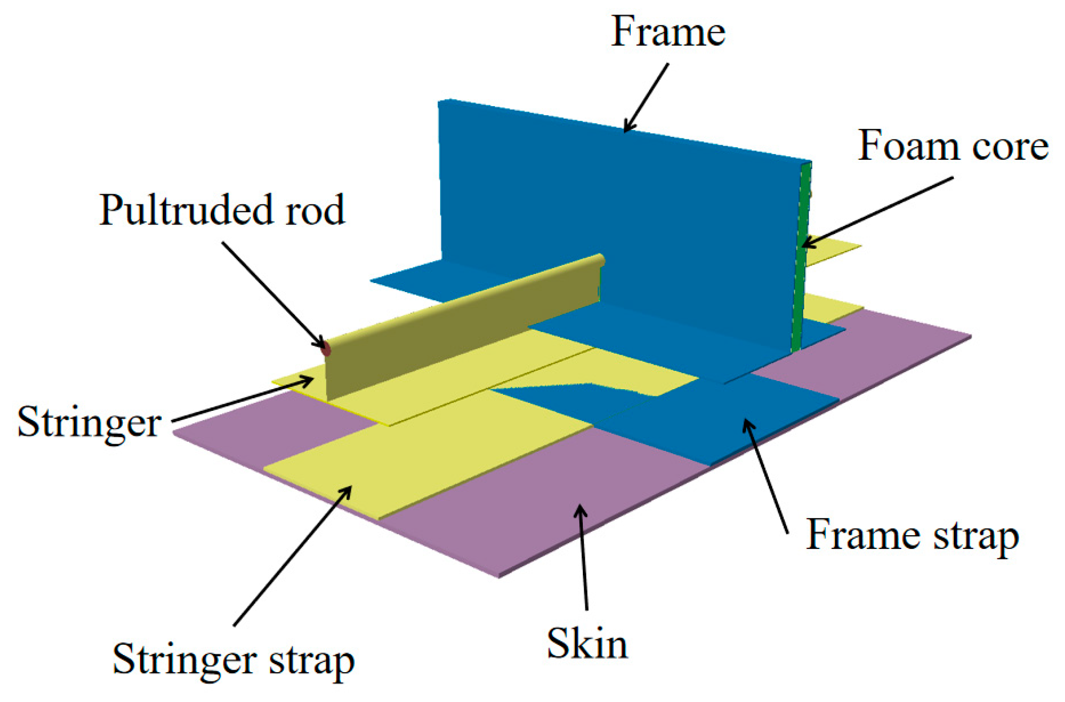
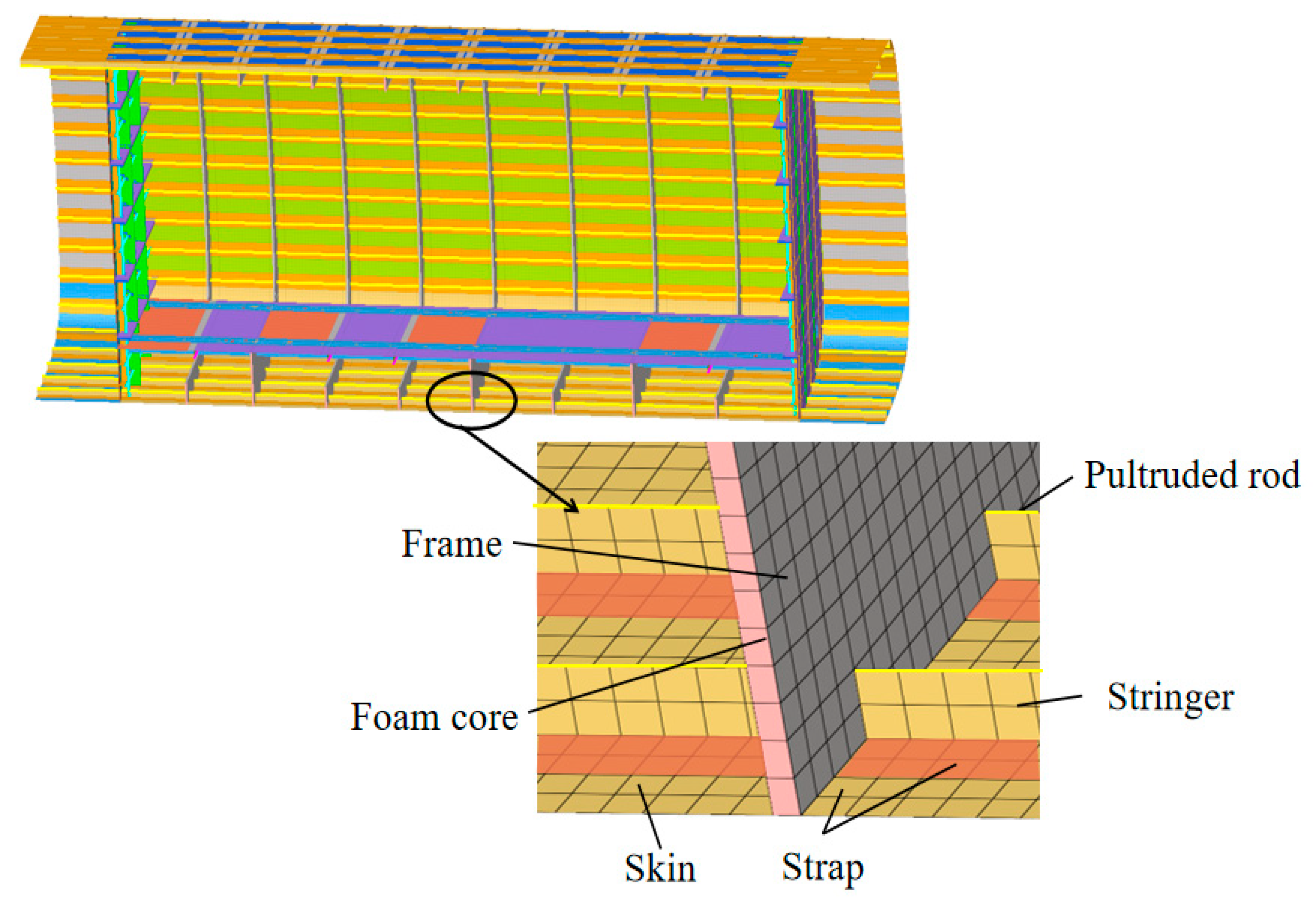
PRSEUS structures provide enhanced structural load-bearing capacity, higher damage and flexural resistance, and lightweight characteristics compared to conventional structures. A typical PRSEUS structure, as shown in Figure 2, consists of dry knitted fibers, pre-cured pultruded rods, and a foam sandwich material, assembled and co-cured with high-density stitching, which achieves fiber shear characteristics between structural elements and continuous load transfer paths [17,18,19,20]. Advanced fabrication techniques such as knitting, resin filling, thickness stitching, and single-sided stitching realize highly integrated PRSEUS structures [16,21,22,23,24].
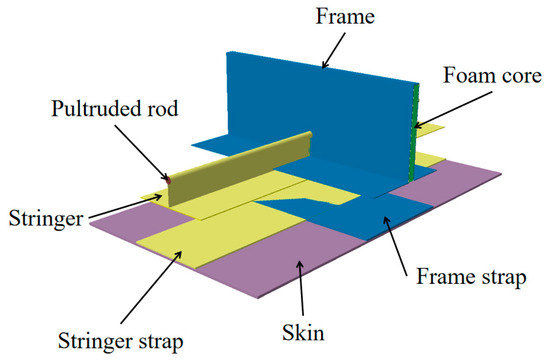
Figure 2.
Typical PRSEUS structural composition.
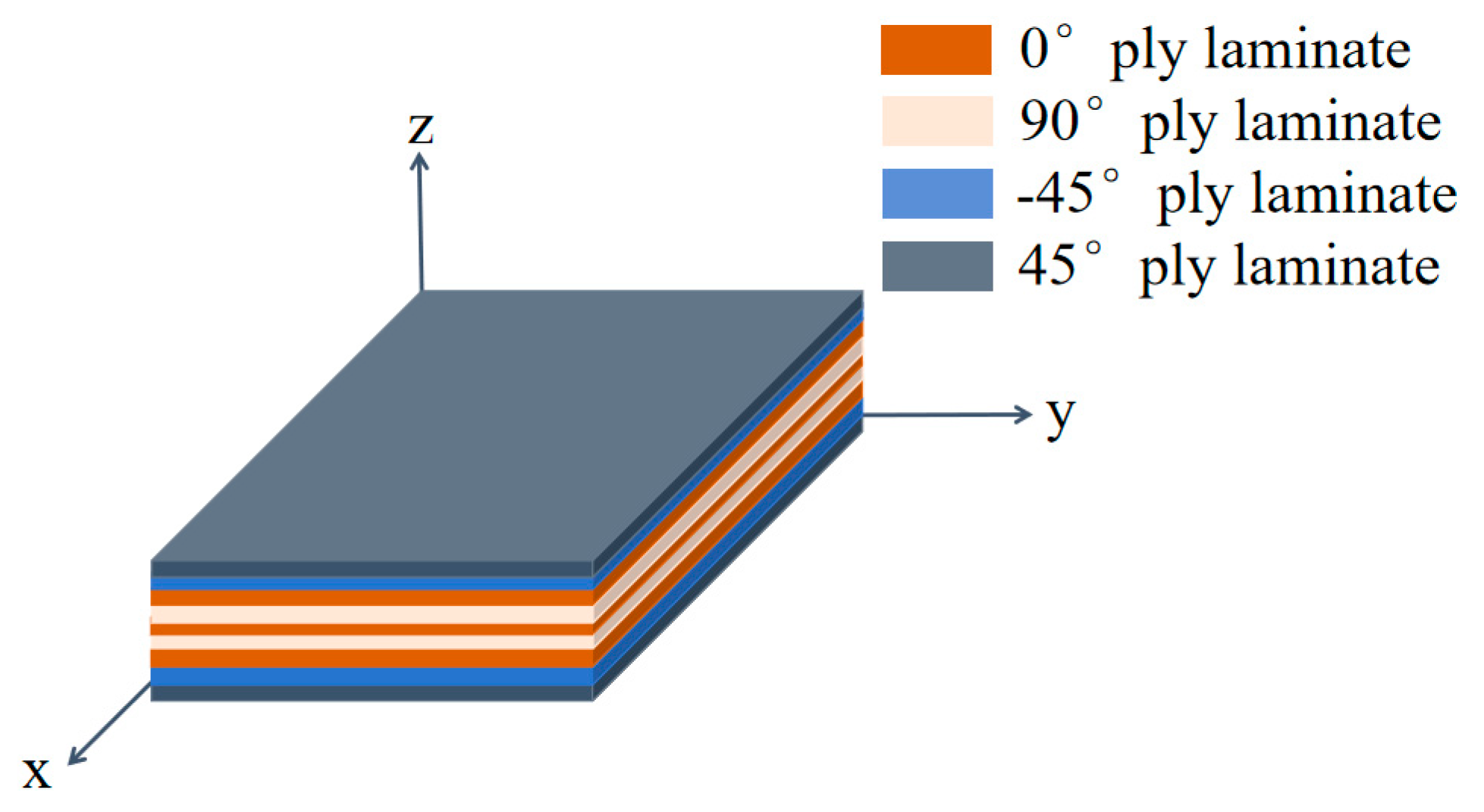
Laminates are composed of two or more layers of single-layer panels bonded together. Typical plywood lay-ups are shown in Figure 3. The sequence and angle of the layers in these panels can significantly influence the mechanical properties of the laminate. Even when one or more layers are damaged, the laminate retains the ability to bear loads, thereby maintaining robust mechanical properties under various loading conditions.
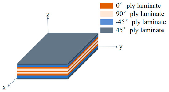
Figure 3.
Typical laminate structure diagram.
3.1. Selection of Materials for the Pressurized Cabin Model
Table 2, Table 3 and Table 4 present the materials and material parameters used in each scheme. This paper details the preliminary design of the pressurized cabin structure, utilizing single-layer continuous carbon fiber-reinforced prepreg tape for the composite materials. In configurations involving composite materials, the lay-up direction of the composites comprises 40% to 45% of the layers at 45° and −45° angles, 40% to 45% at 0°, and 5% to 15% at 90°. A symmetrical and uniform lay-up sequence is implemented. The composite paving parameters for each design are outlined in Table 5, Table 6 and Table 7.
Table 2.
Parameters of aluminum honeycomb, pultruded rods, and foam core of frames.
Table 3.
Metallic material parameters.
Table 4.
Carbon fiber composite material parameters.
Table 5.
Scheme 4–6 composite material ply parameters.
Table 6.
Schemes 7 and 8 composite material ply parameters.
Table 7.
Scheme 9 composite material ply parameters.
3.2. Mesh Geometry of Pressurized Cabin Structure Configuration
In this paper, the middle fuselage half-mold of this type of rotorcraft is selected for the structural configuration design of the pressurized cabin. Schemes 1–3 utilize all-alloy materials, Scheme 9 employs a laminate structure for the composite materials, while Schemes 7 and 8 adopt a PRSEUS structural design. Hybrid Schemes 4–6 combine alloy materials with composite laminate structures. Detailed elaborations on Schemes 2, 5, 7, and 9 are provided in this paper.
Scheme 2, an alloy material modeling scheme, utilizes AL7075 and AL2024 aluminum alloys to examine the influence of metal material properties on model construction. The S4R and S3R elements are established at the spacer frames, skins, and floors of the pressurized cabin, while the BAR2 element units are placed at the stringers, beams, and stiffeners.
The mesh geometry of scheme 2 is shown in Figure 4. The frame spacing is determined by the position of the reinforcing frame, ranging between 390.0 and 480.0 mm. The spacer frames have a height of 80.0 mm with an average thickness of 5.0 mm, while the reinforcing frames have a height of 120.0 mm and an average thickness of 6.3 mm. The stringers are spaced at 180.0 mm with a T-shape design, and the size of the long truss is adjusted according to the load-bearing requirements. The girders have a height of 100.0 mm and a thickness of 5.2 mm. The thickness of the front and rear fuselage separating surfaces of the pressurized cabin is 7.0 mm, the floor thickness is 2.0 mm, and the skin thickness of the middle fuselage is 1.7 mm.
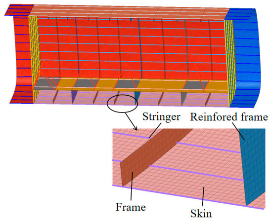
Figure 4.
Finite element model for Scheme 2.
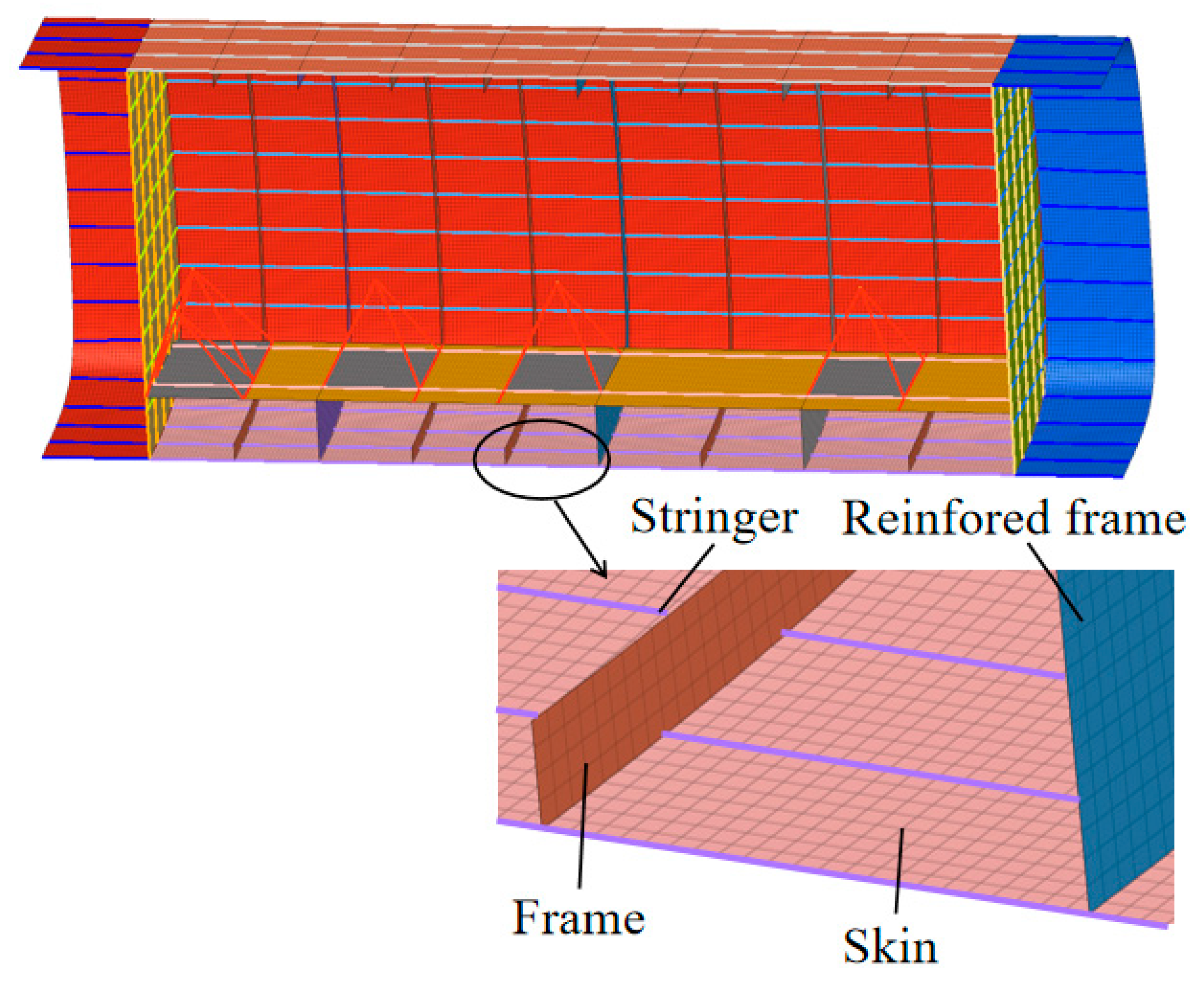
The mesh geometry of scheme 5 is shown in Figure 5. Scheme 5 is a hybrid configuration modeling scheme that utilizes AL7075 aluminum alloy for the primary load-bearing structure and composite materials for the secondary load-bearing structure. The S4R and S3R elements are established at the spacer frames, skins, and floors of the pressurized cabin, while the BAR2 elements units are placed at the stringers, beams, and stiffeners.

Figure 5.
Finite element model for Scheme 5.
Pressure frames and reinforcement frames for pressurized tanks are placed at intervals of 785 mm, 1290 mm, 950 mm, and 975 mm. The spacer frames have a height of 80.0 mm with an average thickness of 4.5 mm, while the reinforcing frames have a height of 120.0 mm and an average thickness of 7.5 mm. The stringers are spaced at 194.0 mm with a T-shape design, and the size of the long truss is adjusted according to the load-bearing requirements. The girders have a height of 110.0 mm and a thickness of 5.5 mm. The thickness of the front and rear fuselage separating surfaces of the pressurized cabin is 4.6 mm, the floor thickness is 1.5 mm, and the skin thickness of the middle fuselage is 1.5 mm.
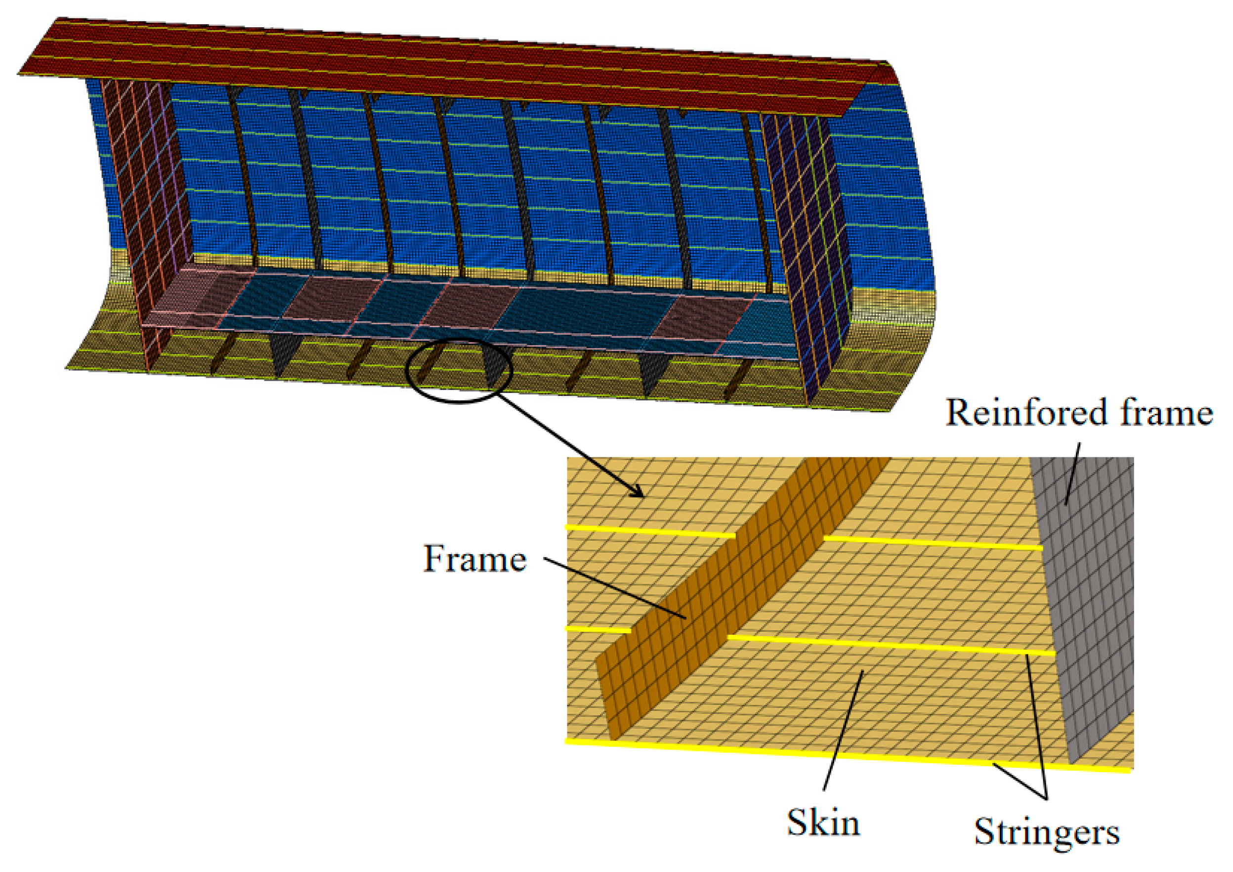
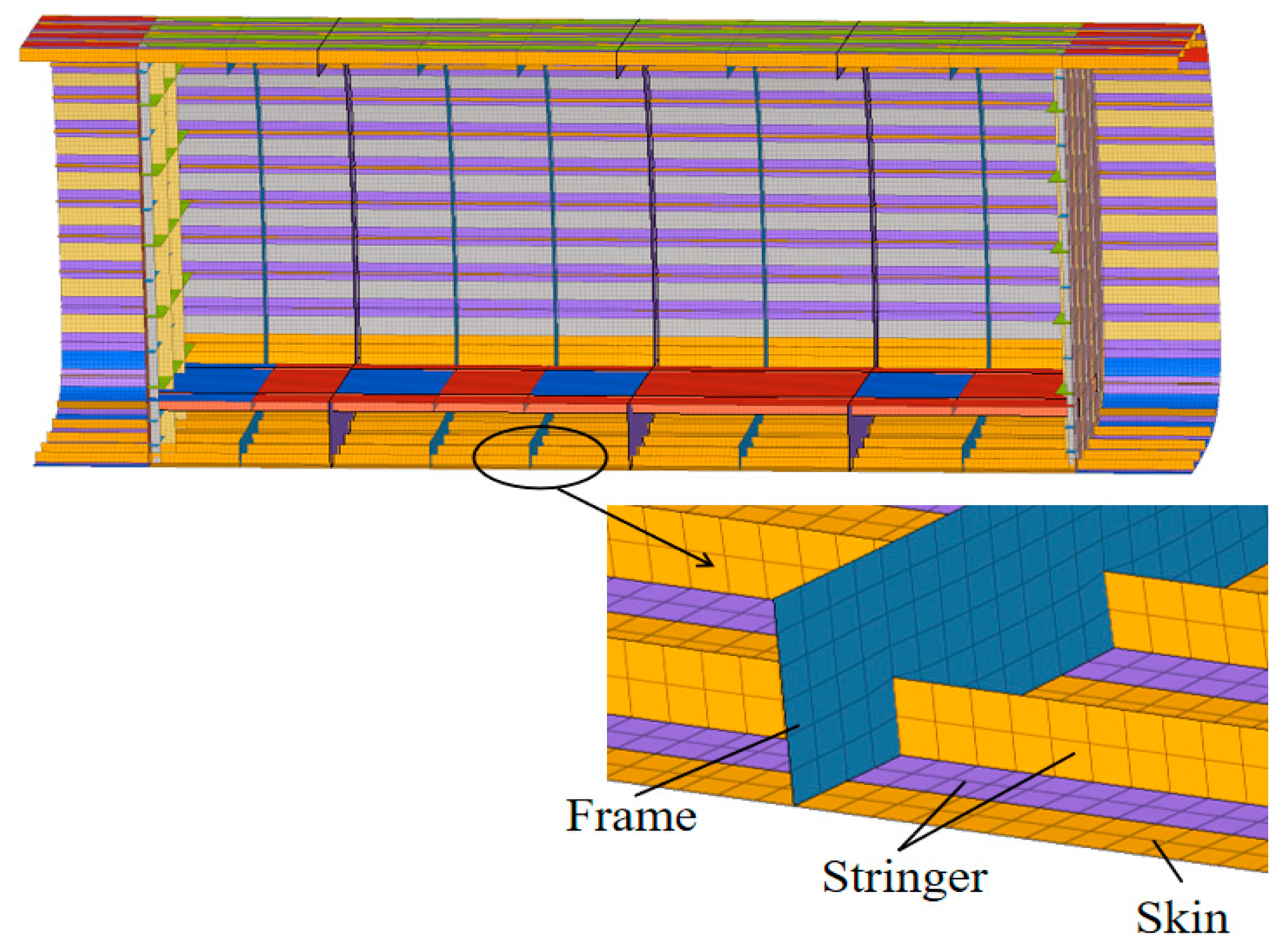
The mesh geometry of scheme 6 is shown in Figure 6 and Figure 7. Scheme 7 utilizes the PRSEUS structural concept, which employs a complex design approach that accounts for the spatial configuration of the woven structure and the technology of stitching connections. This approach demands high precision and meticulousness in modeling. The components such as the booster cabin skin, separation surfaces, stringers, bulkhead wrappers, tear straps, and the cabin floor are modeled using S4R and S3R elements composed of T300 and T800 carbon fiber composites. The bulkhead’s foam core is modeled as a solid unit using Rohacell foam, while pultruded rods, made from T800 carbon fiber and 3900-2B resin, form the BAR2 elements.
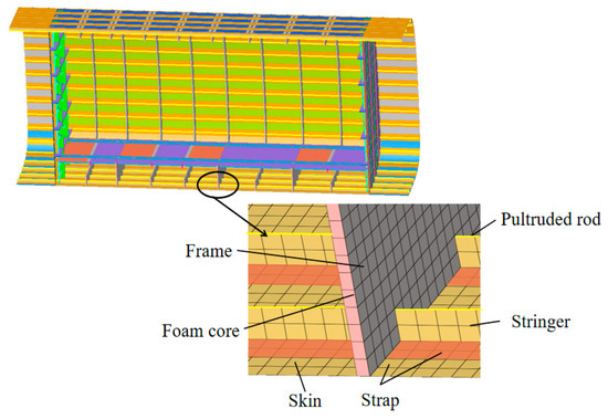
Figure 6.
Finite element model for Scheme 7.
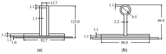
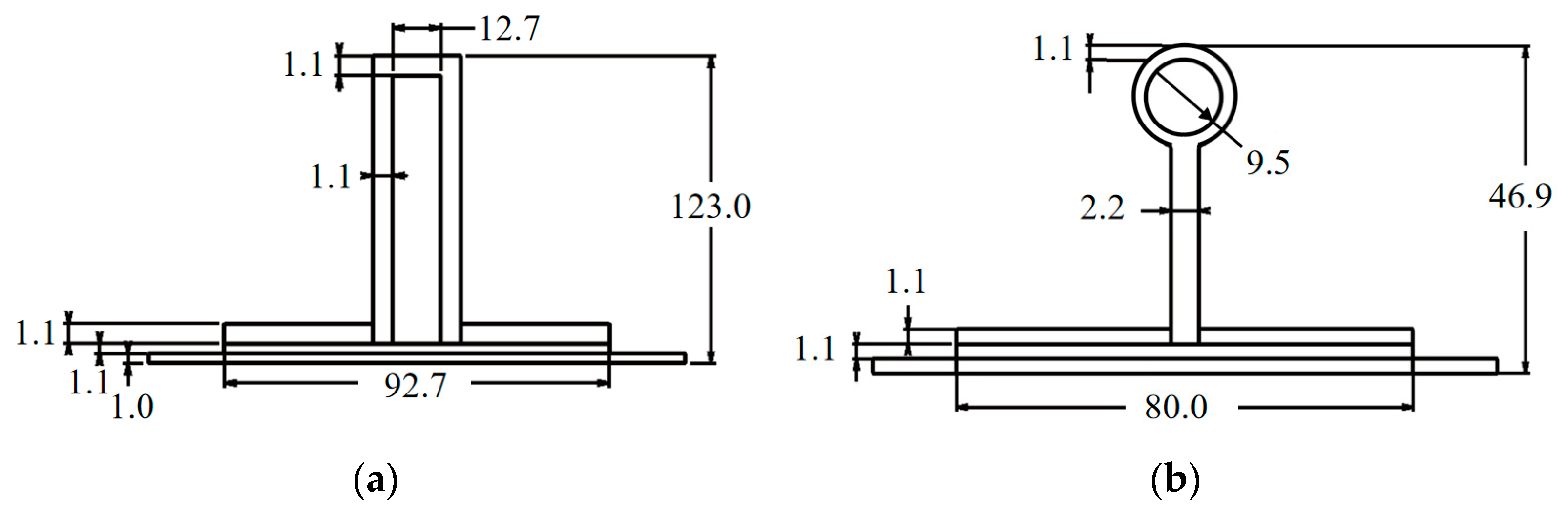
Figure 7.
Frame and stringer size for Scheme 7 (unit: mm). (a) Frame size; (b) stringer size.
The spacer frames are spaced between 390.0 mm and 480.0 mm and have a height of 123.0 mm. The stringers are set at 160.0 mm apart with a combined height of 46.9 mm with the pultruded rods. The separating surface thickness between the front and rear fuselage of the pressurized compartment is 4.8 mm, the cabin floor thickness is 1.8 mm, and the skin thickness of the pressurized cabin is 1.0 mm.
The mesh geometry of scheme 9 is shown in Figure 8. Scheme 9 adopts an all-composite laminate configuration, utilizing T300 and T800 carbon fiber composites. This configuration highlights the multilayer structure of the composite material and demonstrates the impact of performance variations between layers on the simulation results. The structure is meshed using S4R and S3R elements.
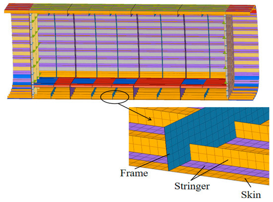
Figure 8.
Finite element model of Scheme 9.
The ply design is applied to stringers and frames. The spacing of the spacer frames aligns with the location of the reinforcement frames, ranging from 390.0 mm to 480.0 mm, with frame heights of 120.0 mm and an average thickness of 3.5 mm. Stringers are spaced at 164.0 mm with a height of 45.0 mm. The thickness of the separating surface between the front and rear fuselage of the pressurized cabin is 6.7 mm, the floor thickness is 1.0 mm, and the skin thickness of the pressurized cabin is 1.2 mm.
3.3. Load Loading and Boundary Conditions
In addressing the performance requirements of high-speed rotorcraft at high altitudes, the comfort of the passengers within the cabin must be considered, ensuring the internal environment is maintained at one atmosphere. The focus of load applications is on assessing the rationality and feasibility of the pressurized cabin configuration under pressurized loads, gravity, and floor loads, without considering secondary factors such as out-of-limit loads, vibration, and fatigue.
In this scenario, the boost load and floor load are applied as pressures, while gravity is modeled as a gravitational field. The conditions for structural load application are detailed in Table 8.
Table 8.
Structural load application conditions.
In the table, represents the pressure difference between the inside and outside of the pressurized cabin at a specified cruising altitude; n is the coefficient of the maximum pressurized load the aircraft structure is designed to withstand, set at 1.33; f is the structural design safety factor, at 1.5; M is the mass of the pressurized cabin’s structure; is the acceleration due to gravity; m is the mass of passengers and cargo on the floor.
With the civilian high-speed rotorcraft cruising at an altitude of 3000 m, the pressurized cabin load calculations are as follows:
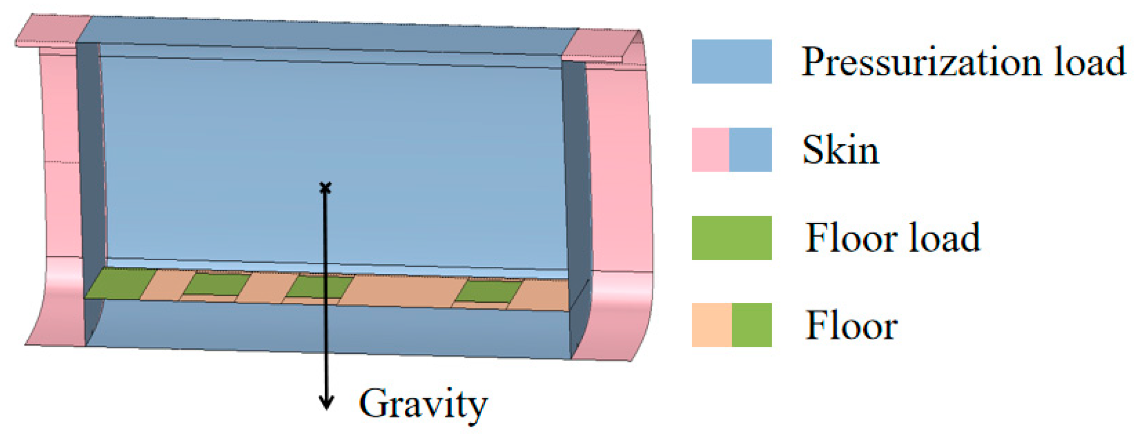
Here, is the standard atmospheric pressure, is the flight altitude, is the cabin pressure difference, and P is the pressurized load used in the analysis. The load application is illustrated in Figure 9, where the weight of a single seat and passenger is 101 kg.
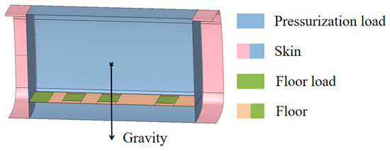
Figure 9.
Structural load schematic diagram.
This paper outlines the preliminary design of a civil high-speed rotorcraft pressurized compartment structure configuration; the structure does not consider the composite delamination problem, and only the target strength and stiffness are calibrated. In order to make sure that the mesh size has no effect on the simulation results of the model, we should perform a mesh convergence analysis on the model because the models have the same dimensions; therefore, we only perform a network convergence analysis on the pressurized compartment structure of Scheme 1.
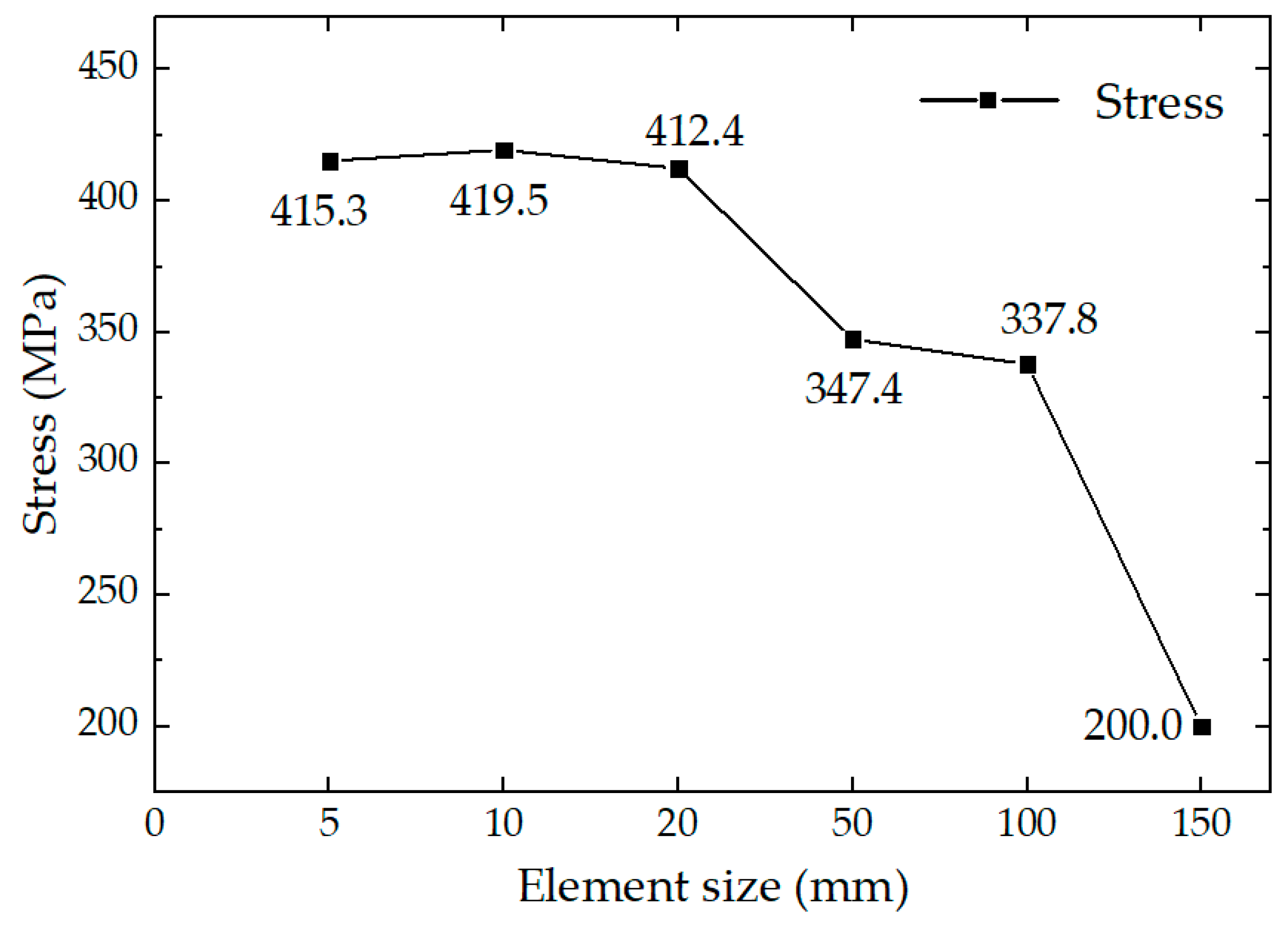
Figure 10 shows the maximum stress values at different mesh scales. The simulation results show that the stress maps of the PRESUS wall model exhibit similarity at each mesh scale, and the maximum stress values are all located at the same position. According to the analysis results, when the mesh size is less than or equal to 20 mm, the calculation results show a convergence trend. Therefore, this paper adopts 20 mm as the grid size for meshing the model.
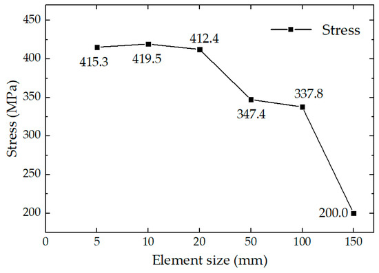
Figure 10.
Mesh convergence analysis.
For this paper, the middle fuselage of a specific rotorcraft is selected for model simplification, and the impacts of the front and rear fuselage on the pressurized cabin configuration are disregarded. Consequently, it becomes essential to address the boundary issues at both ends of the pressurized cabin. The model of the middle fuselage pressurized cabin segment is extended outward by 50 mm, 100 mm, and 500 mm to apply fixed constraints, and symmetric boundaries are established on the symmetric plane to facilitate model simulations. The outcomes of these simulations are presented in Table 9.
Table 9.
Simulation results for different external extension lengths of the pressurized cabin.
The trends in stress and deformation across the three sets of simulation models are consistent; both the maximum stress and maximum deformation occur at the same location. Using an outer extension length of 1000 mm as the baseline, the models with varying outer extension lengths are analyzed for discrepancies. The maximum von Mises stress error is 0.59% and the maximum deformation error is 1.17% for the model with a 50 mm outer extension. For the model extended by 500 mm, the maximum von Mises stress error is reduced to 0.21% and the maximum deformation error is reduced to 0.54%, with the error falling within six-thousandths of a percent. As the outer extension length increases, there is a notable reduction in model error, which also enhances the computational efficiency of the model due to a decrease in the number of meshes.
Based on the findings from the analysis, this paper selects the model with a 500 mm outer extension of the middle fuselage pressurized cabin as the primary focus.
4. Finite Element Simulation Results of the Structural Configuration Scheme of the Pressurized Compartment
4.1. Finite Element Simulation Results
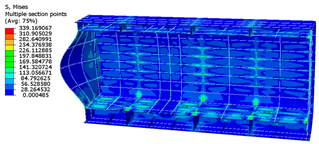
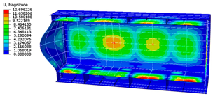
ABAQUS2022 is used for the finite element simulation analysis in this paper. The simulation of the model reveals that large displacements or shape changes due to the initial stress or the rigidification from initial loads can render the model geometrically nonlinear. Consequently, this paper conducts a nonlinear finite element analysis of the pressurized cabin structure. We analyze displacement and stress (strain) levels across nine scenarios; large deformations are not observed, and the results are presented in Figure 11, Figure 12, Figure 13, Figure 14, Figure 15, Figure 16, Figure 17, Figure 18 and Figure 19.
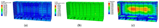
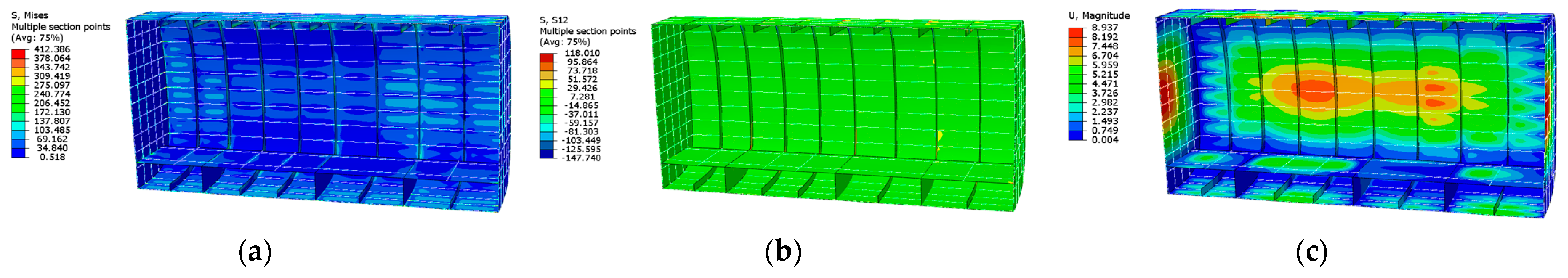
Figure 11.
Scheme 1 finite element simulation results. (a) Structural von Mises stress; (b) structural shear stress; (c) structural displacement.
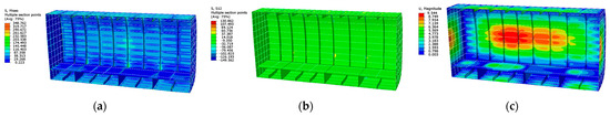
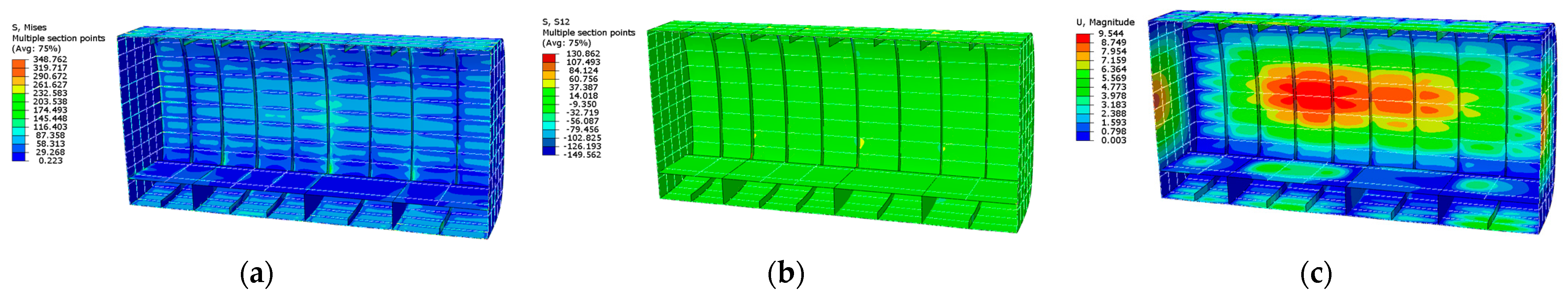
Figure 12.
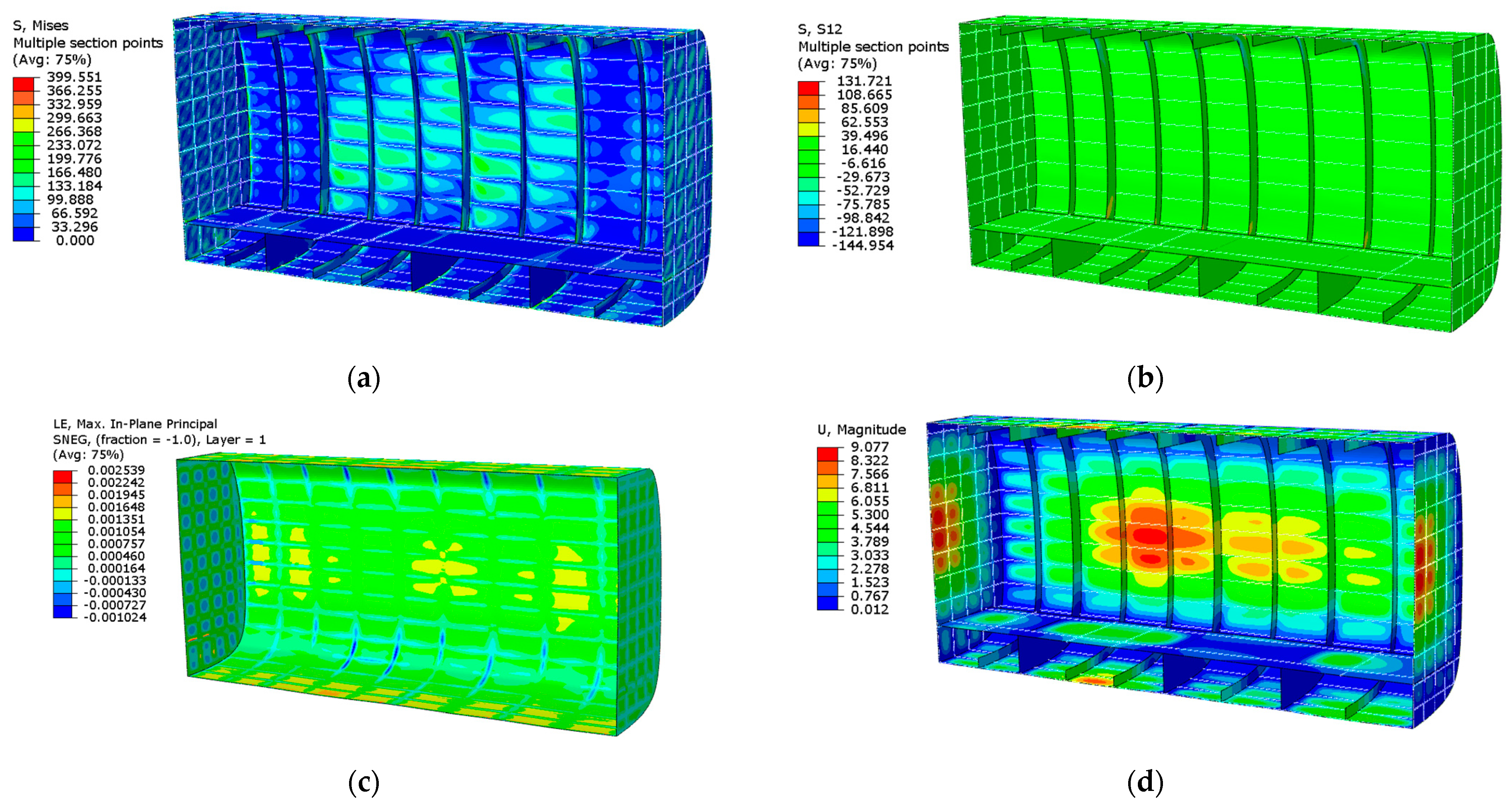
Scheme 2 finite element simulation results. (a) Structural von Mises stress; (b) structural shear stress; (c) structural displacement.
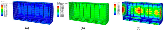
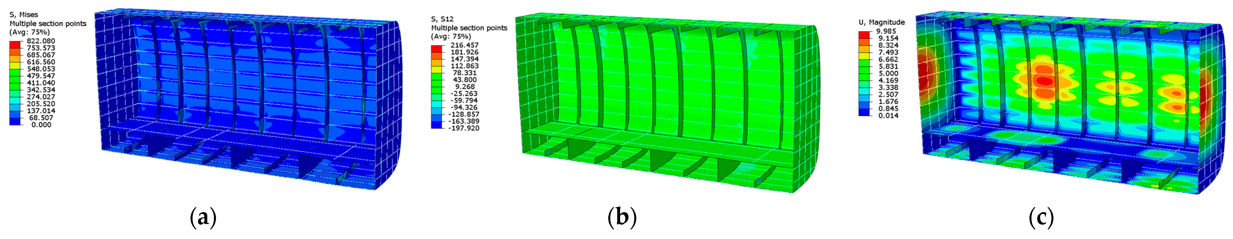
Figure 13.
Scheme 3 finite element simulation results. (a) Structural von Mises stress; (b) structural shear stress; (c) structural displacement.
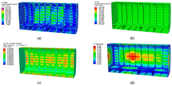
Figure 14.
Scheme 4 finite element simulation results. (a) Structural von Mises stress; (b) structural shear stress; (c) T300 composite strain; (d) structural displacement.
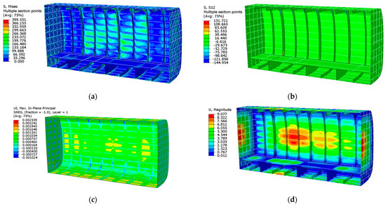
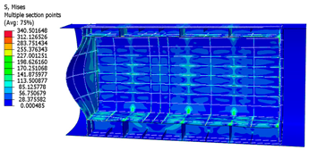
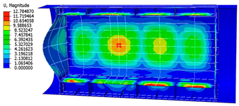
Figure 15.
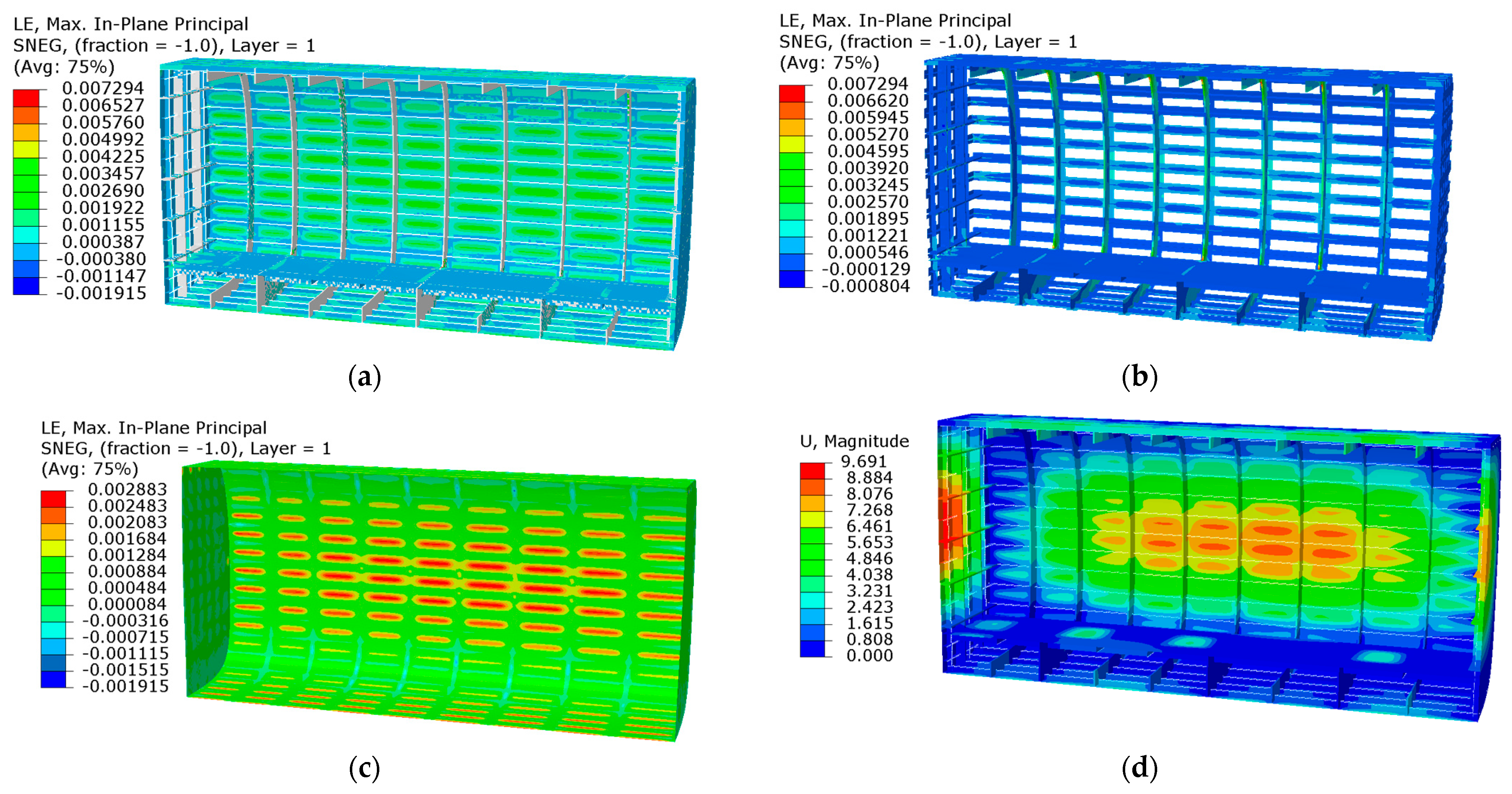
Scheme 5 finite element simulation results. (a) Structural von Mises stress; (b) structural shear stress; (c) T300 composite strain; (d) structural displacement.
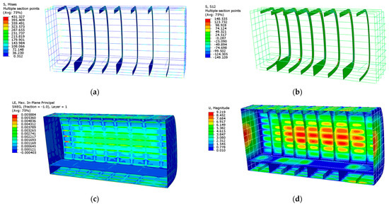
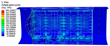
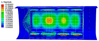
Figure 16.
Scheme 6 finite element simulation results. (a) AL7075 von Mises stress; (b) AL7075 shear stress; (c) T800 composite strain; (d) structural displacement.
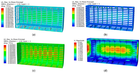
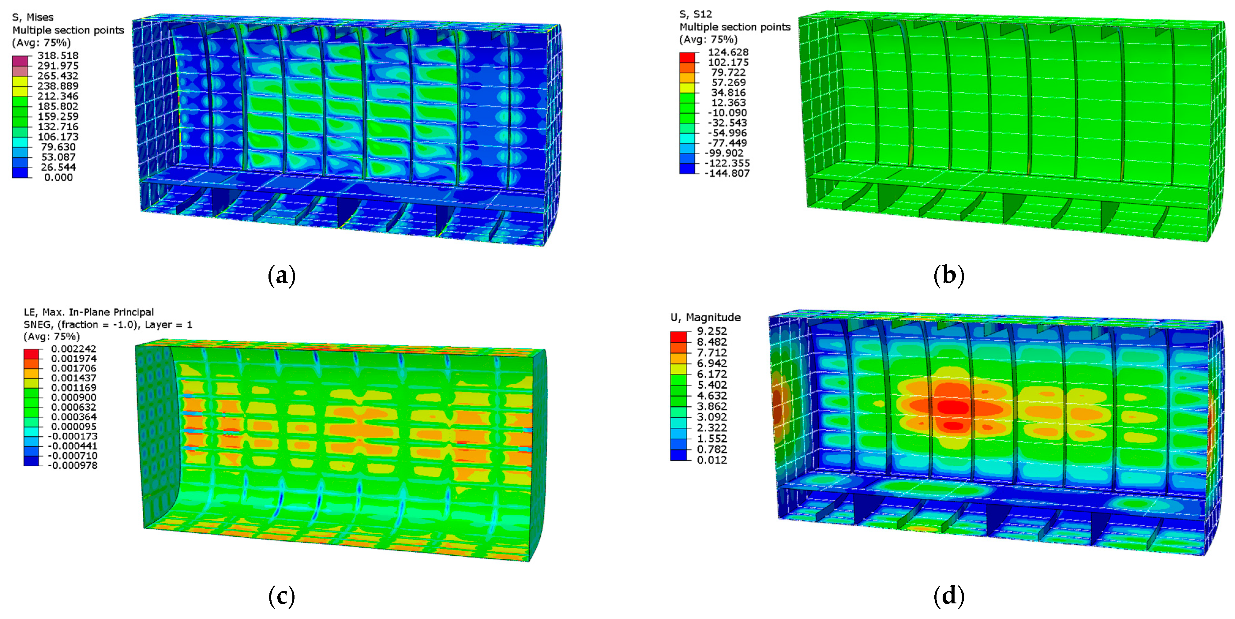
Figure 17.
Scheme 7 finite element simulation results. (a) Structure strain; (b) T800 composite strain; (c) T300 composite strain; (d) structural displacement.
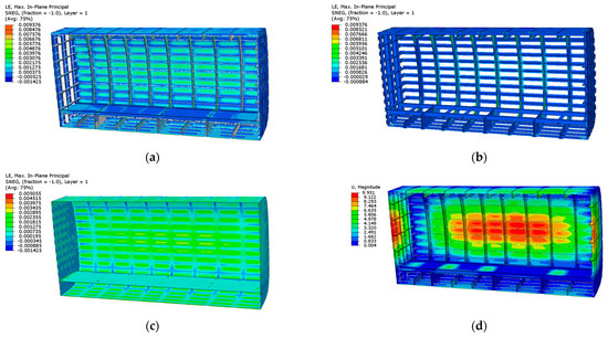
Figure 18.
Scheme 8 finite element simulation results. (a) Structure strain; (b) T1000 composite strain; (c) T800 composite strain; (d) structural displacement.
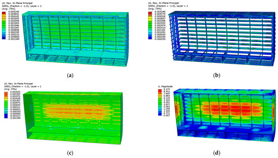
Figure 19.
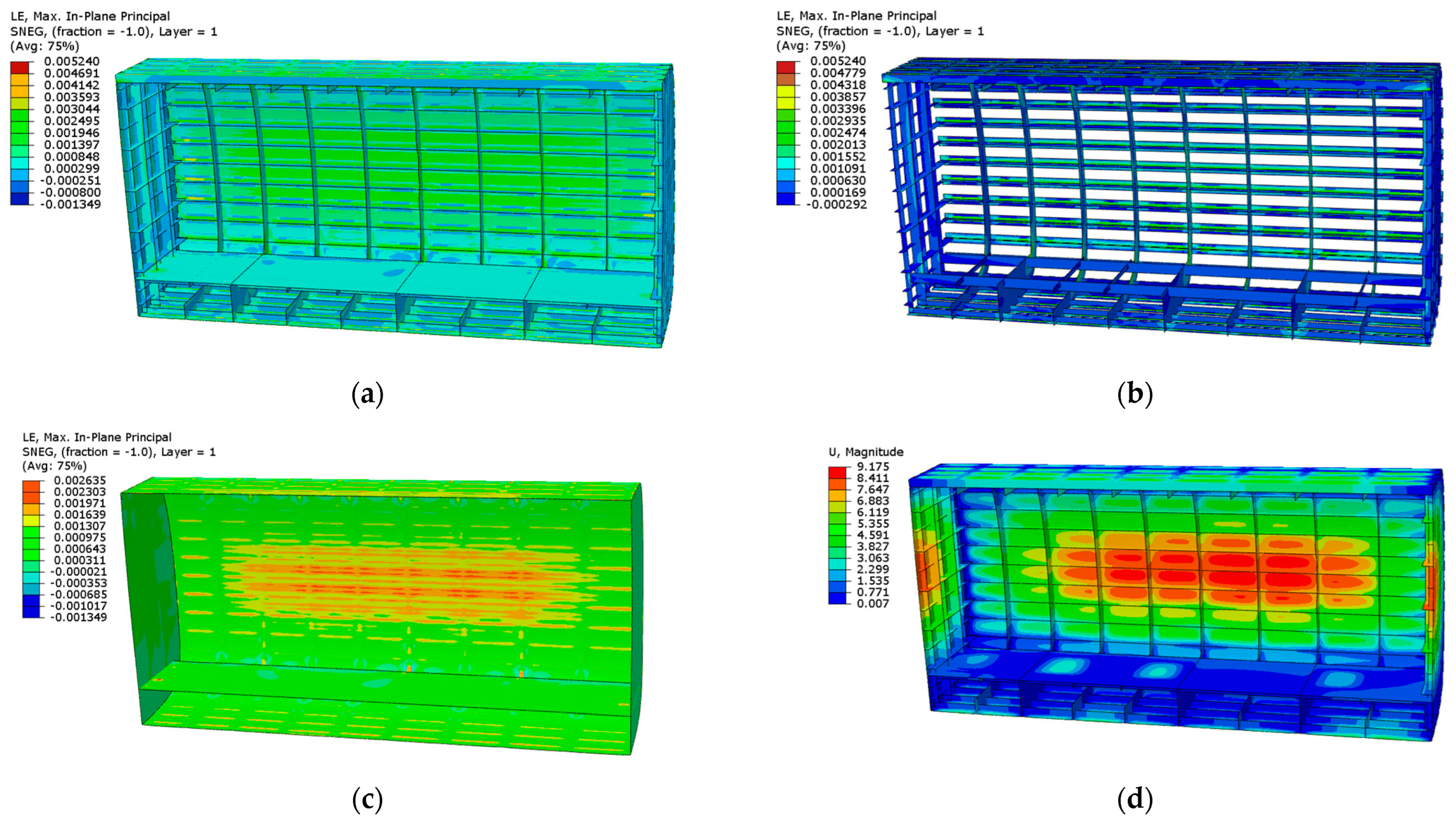
Scheme 9 finite element simulation results. (a) Structure strain; (b) T800 composite strain; (c) T300 composite strain; (d) structural displacement.
The constraints for the nine scenarios are as follows: the maximum equivalent displacement must be less than 10 mm; the maximum von Mises stress for the alloy material must not exceed the material’s yield strength; the maximum shear stress should remain below the shear strength of the material; and for composite materials, the maximum equivalent strain must not surpass the allowable strain.
All scenarios satisfy the static strength and stiffness requirements set for the design of the pressurized cabin’s structural configuration. Specifically, Scheme 3 experiences the highest structural stress at 822.1 MPa, Scheme 8 displays the highest equivalent strain at 9376 , and Scheme 1 exhibits the smallest structural configuration displacement at 8.937 mm, highlighting the distinct variations across the results.
Under pressurized load conditions, the structure exhibits significant displacements and deformations, particularly in the separating surface and skin region. The frame, crucial for maintaining the structural integrity, primarily endures shear stresses. Conversely, stringer and beam structures bear the brunt of tensile and compressive stresses, contributing significantly to the von Mises stresses of the structure. These stresses typically concentrate on structural elements such as stringers and beams. Due to varying load capacities among components, local stress concentrations are observed. Notably, the floor experiences substantial displacements of 4–5 mm due to direct floor loading.
Table 10 outlines potential risk sources for each scenario, derived from the simulation results. For instance, in Schemes 1, 2, 5, and 6, the maximum shear stress of structures utilizing AL7075 material approaches the shear strength limits. In Schemes 3 and 8, the maximum equivalent displacement nears the structural constraints’ limits. For Scheme 4, which employs AL2024 material, the maximum von Mises stress is close to the material’s yield strength. Meanwhile, in Schemes 7 and 9, which involve T300 carbon fiber composite, the maximum equivalent strain approaches the permissible strain range.
Table 10.
Potential risk sources for each scheme.
Table 11 compares the weight of each structural scheme with its maximum deformation and other factors. From the table, it is evident that Scheme 8 offers a lighter configuration, where the weight of the pressurized cabin is 284.4 kg, marking an 8.73% reduction compared to Scheme 9. Conversely, Scheme 2 is the heaviest, weighing 131.07% more than Scheme 9. The weight of the pressurized cabin half-mold in the all-metal alloy configuration exceeds 300 kg. The use of composite materials significantly reduces the weight of the structural configuration; the all-metal alloy structure is over 100% heavier than the all-composite structure, while the hybrid configurations (Schemes 4–6) show a weight increase of more than 60% compared to the all-composite structure. The smallest displacement recorded is 8.937 mm in Scheme 1, and the largest is 9.985 mm in Scheme 3.
Table 11.
Simulation results of the nine structural configuration schemes.
4.2. Analysis of Structural Component Weights
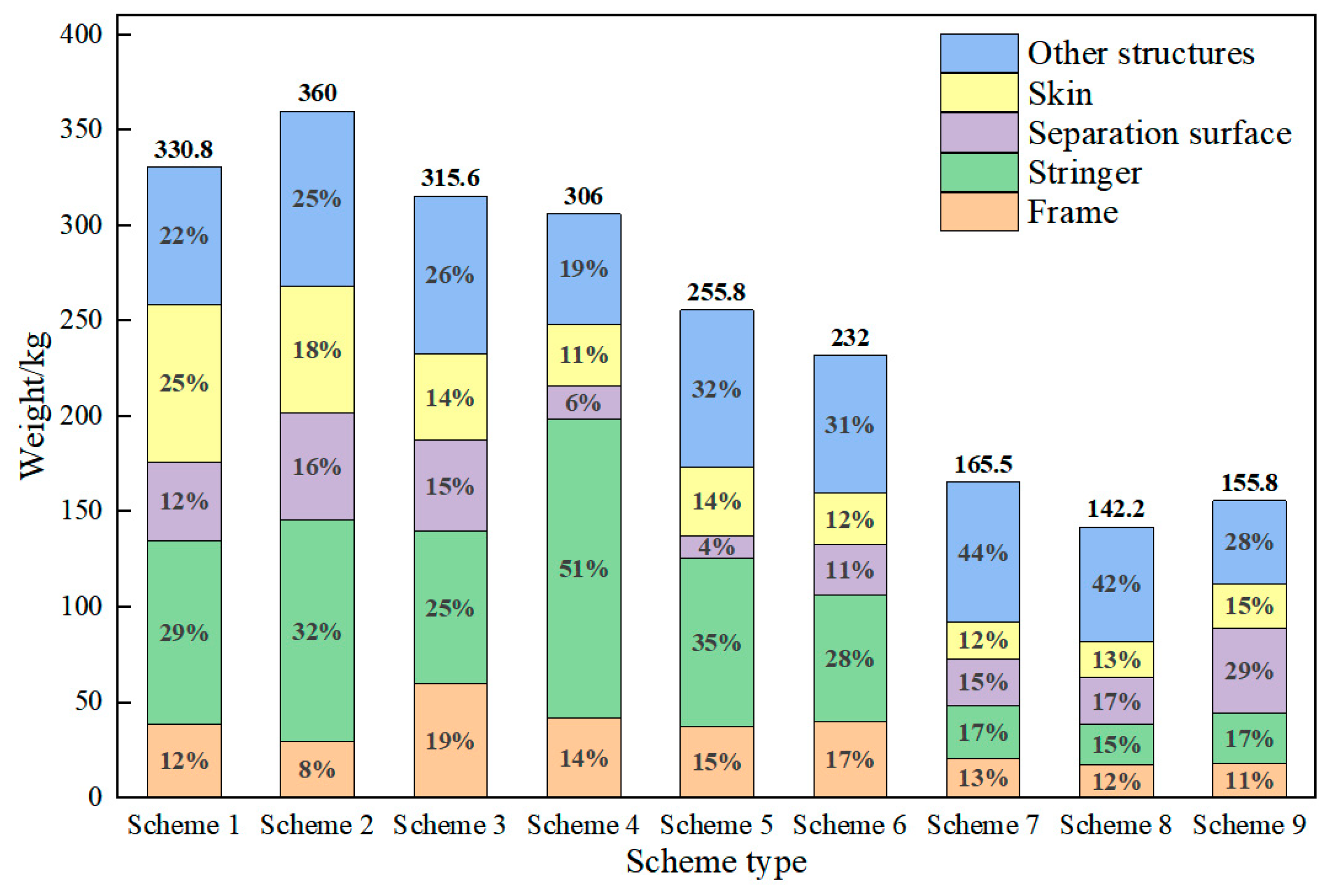
As illustrated in Figure 20 and Figure 21, the frame’s weight in the design of the civil high-speed rotorcraft pressurized cabin varies from 8% to 19% of the total structure. In the all-aluminum alloy configuration, increasing the frame’s weight contributes to the overall stiffness distribution, thereby reducing the structural weight. In configurations containing titanium alloy, the frame’s weight increases due to the superior mechanical properties of titanium alloy, which has significantly greater stiffness and strength than aluminum alloy, allowing it to bear more load during stiffness distribution.
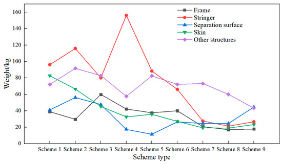
Figure 20.
Weight variation of components in the pressurized cabin.
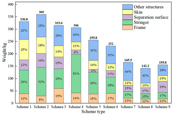
Figure 21.
Weight proportion of components in the structural configuration of the pressurized cabin.
The weights of stringers and beams in different structural configurations vary substantially based on the materials used, processing technology, and spacing. In metal alloy configurations, the weight of stringers and beams ranges from 25% to 33%. In the hybrid configurations, this range is 28% to 50%. In the all-composite configurations, stringers account for 15% to 17% of the weight. Increasing the spacing of stringers can reduce the overall weight of the structure, whereas enhancing the beam structure can increase the load-carrying capacity of the components.
There is a notable variation in the weight of separating surfaces across different pressurized cabin configurations. In all-metal-alloy configurations, the weight of separating surfaces ranges from 12% to 16%. In hybrid configurations, where less dense composite materials are used, this percentage is within 10%. For the PRSEUS configuration, the separation surface and its reinforcing structure are interconnected by stitching to facilitate force transfer, accounting for 15% to 18% of the weight. In all-composite laminate configurations, the separation surface structure must be heavier to meet safety and stability requirements due to its inability to perform structural crack stopping and force transfer duties, thus accounting for more than 20% of the weight.
The skin’s weight in the pressurized cabin’s structural configuration ranges from 11% to 25%, with thicknesses varying between 1.0 mm and 2.0 mm.
5. Comparative Analysis of Nine Scheme
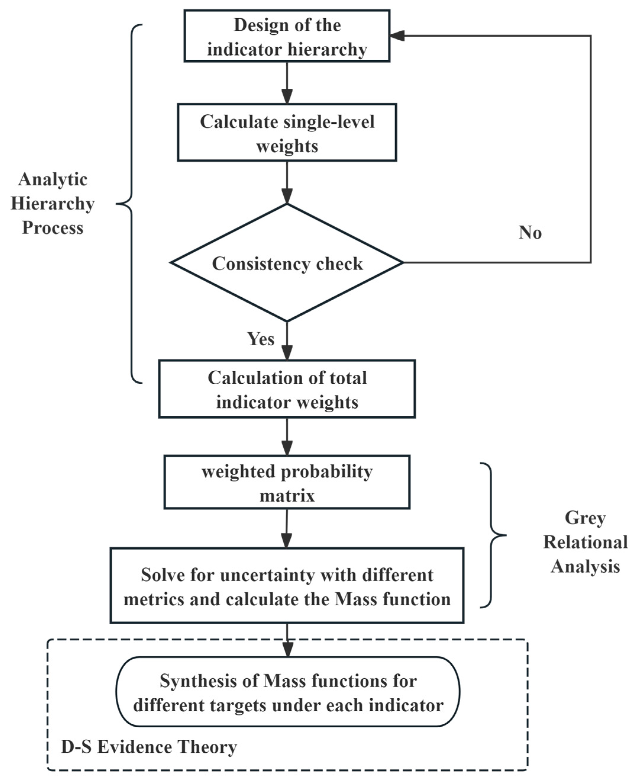
Utilizing the Analytic Hierarchy Process (AHP) and combining it with Gray Relational Analysis (GRA) and D-S evidence theory [25,26,27,28,29], this section endeavors to perform a comprehensive evaluation of the nine proposed pressurized cabin structure options. The AHP refers to the evaluation of the design schemes of a civil high-speed rotorcraft pressurized cabin as a system, which decomposes the objectives into multiple objectives, and then into several levels of multiple indicators, and calculates the hierarchical single ranking (weights) and total ranking through the fuzzy quantification of qualitative indicators. GRA is a method of measuring the degree of correlation between factors based on the degree of similarity or dissimilarity of the development trend of the factors, and it can be calculated and ranked through the gray correlation method. GRA is a method to measure the degree of correlation between factors according to the degree of similarity or dissimilarity between the development trends of the factors, and through the Gray Relational Analysis, the probability of choosing the program under each indicator can be obtained and ranked. D-S evidence theory combines the probability of choosing the program under each indicator with the index ranking obtained by the hierarchical analysis method to integrate, so as to obtain the conclusion of the comprehensive assessment of the pressurized cabin program under multiple indicators.
The evaluation is conducted across three dimensions: production cost, technological maturity and machining technology, and structural performance. This multifaceted assessment aims to identify the most rational options, providing a foundational reference for the selection and preliminary design of pressurized cabin structures in helicopter configurations. The procedural flow of this evaluation is depicted in Figure 22.
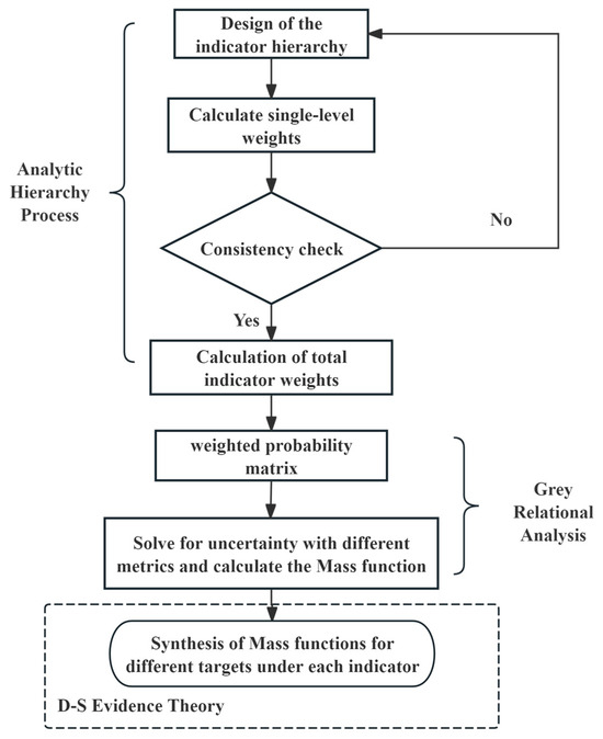
Figure 22.
Evaluation implementation flowchart.
5.1. The Analytic Hierarchy Process
The Analytic Hierarchy Process (AHP), a method of subjective weighting developed by operations research expert Thomas L. Saaty at the University of Pittsburgh in the 1970s, effectively integrates qualitative and quantitative analysis. This methodology hierarchizes indicators within a complex system and constructs a multi-level hierarchical structure for analysis. At each level, indicators are analyzed, compared, and weighted according to their relative importance, thereby simplifying and quantifying complex decision-making scenarios. The accuracy and ease of implementation of AHP have led to its widespread adoption [30].
5.1.1. Booster Compartment Structural Configuration Design Indicator Hierarchy
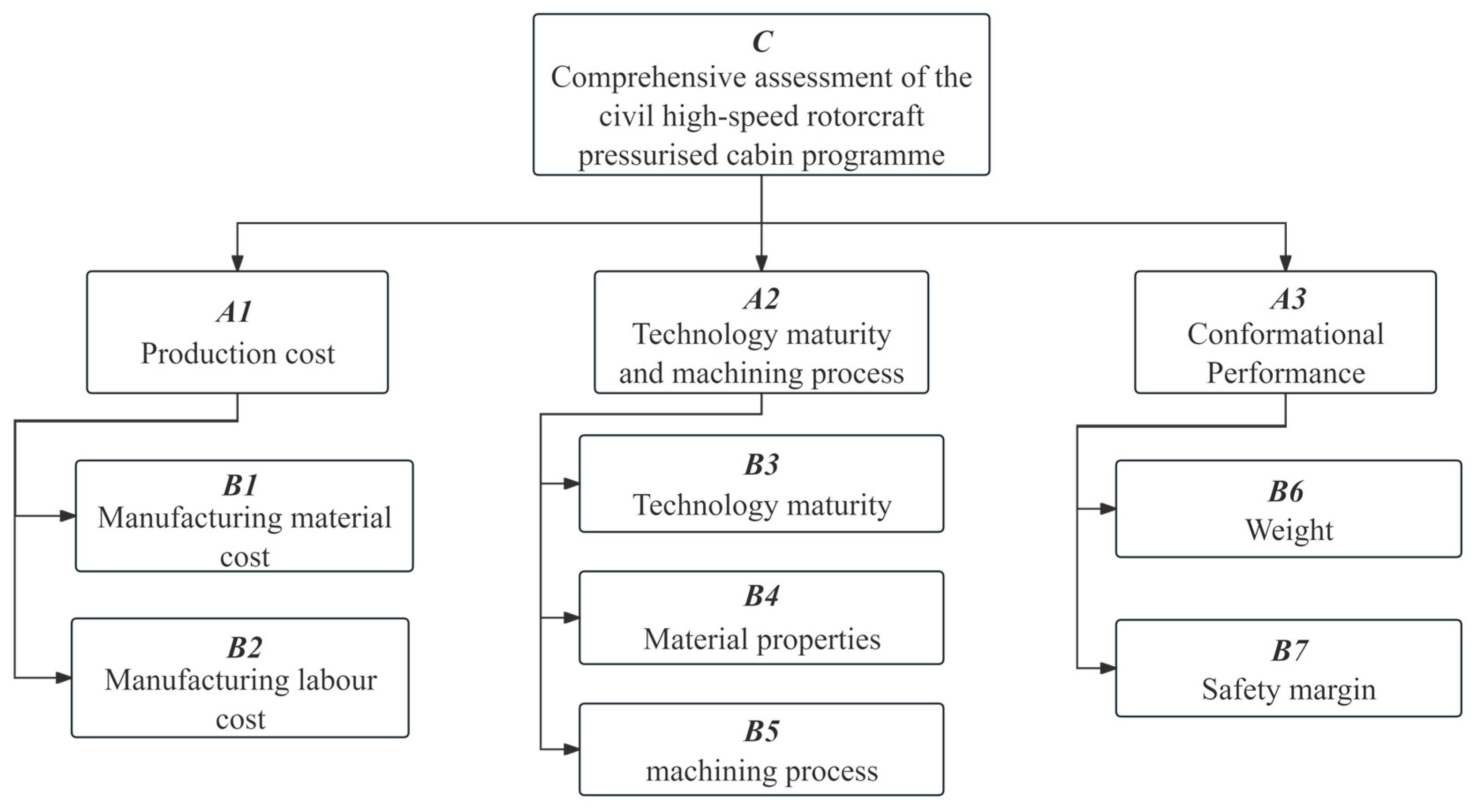
To ensure the accuracy and objectivity of the assessment method, the selection of indicators adheres to criteria that are scientific, advanced, and systemic, combining qualitative and quantitative analyses for feasibility. A hierarchical relationship diagram, as shown in Figure 23, illustrates the structured approach to the pressurized cabin’s design indicators for this paper.
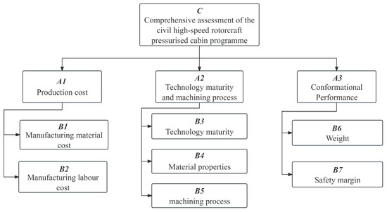
Figure 23.
Hierarchical relationship diagram of design indices for the pressurized cabin structural configuration.
Production cost: This includes the cost of materials used in the manufacturing processes of the rotorcraft pressurized cabin and the labor costs associated with machining, sheet metal fabrication, heat treatment, and part assembly.
Technology maturity and machining process: Technology maturity is a critical component of project risk management that typically spans multiple developmental stages—from conceptual designs to proven, mature products suited for mass production. The maturity level generally increases as the project progresses through these stages. The choice of processing technology influences and determines the feasibility of a technology’s widespread adoption within a market economy, with varying processing techniques impacting the load-bearing capabilities of structural components.
Structural performance: This refers to how the weight of the pressurized cabin affects the aircraft’s performance, structural integrity, and flight efficiency. The safety margin is crucial as it directly pertains to the life and property safety of passengers, crew, and ground personnel, thereby playing a pivotal role in the aerospace vehicle’s configuration design.
The impact on the nine different design options is analyzed across these dimensions to determine the relative weight each dimension holds in the design of the pressurized cabin structure configuration.
5.1.2. Constructing a Judgment Matrix and Assigning Values
In this paper, we employ an expert scoring system, convening a panel of 21 experts in the field of aviation. These experts were tasked with making scaled judgments about the relative importance of elements within each hierarchical layer, utilizing the 1–9 scaling method introduced by Saaty to quantify the results and construct the judgment matrices Aij for the layer indicators [31]. The significance of the importance scale is detailed in Table 12.
Table 12.
Interpretation of the significance scale [31].
Production cost dimension: Both the cost of manufacturing materials and the labor costs associated with manufacturing are identified as critically important and are assessed year-over-year.
Technology maturity and machining process dimension: In this dimension, the maturity of the technology, which measures how well the technology used in the rotorcraft pressurized cabin meets the desired objectives, is prioritized. This is followed by considerations of the processing techniques and material properties.
Structural performance dimension: The safety and the weight index of the pressurized cabin structure are directly related to personnel safety, making these considerations equally crucial.
Based on these analyses, the matrices for economic judgment A1, technology maturity and machining process A2, and structural performance A3 are constructed as follows:
In the comprehensive assessment of civil high-speed rotorcraft pressurized cabin configuration schemes, the production cost significantly impacts market competitiveness, though it assumes a lower priority under the premise of ensuring airworthiness and functional value. At the technical level, both the maturity of technology and the sophistication of the machining process are crucial for the reliability and maintainability of the vehicle, and they hold significance comparable to the economic aspects. The performance of the pressurized cabin configuration is deemed of utmost importance as it directly affects the airworthiness and functional value, pivotal for the successful design and deployment of the cabin structure.
This leads to a judgment matrix C for the three dimensions—production cost, technological maturity and machining process, and safety—as follows:
5.1.3. Determining Single-Level Relative Weights and Consistency Checks
The relative weights of the indicators in the AHP are typically calculated using the sum method, the power method, or the square root method. In this paper, the square root method is utilized as follows:
where i = 1, 2, ..., n.
For the judgment matrix Aij, the largest characteristic root is calculated. When the order of the judgment matrix is three or greater, a consistency test is required. The consistency index CI is calculated as CI = , where n is the order of the judgment matrix. The consistency ratio CR is determined by CR = CI/RI, where RI is the average random consistency index shown in Table 13. A CR within acceptable limits indicates a consistent matrix; otherwise, adjustments are necessary [32].
Table 13.
Stochastic consistency value [32].
Based on the judgment matrices defined in Section 5.1.2, the relative weights of the indicators are shown in Table 14 and Table 15.
Table 14.
Index relative weight.
Table 15.
Index relative weight.
Given the order of the judgment matrices A2 and C, which is three or greater, consistency testing is mandatory. The principal eigenvalue of the judgment matrix A2, pertaining to technological maturity and machining process, is found to be 3.039, with a CR of 0.033. The principal eigenvalue for the judgment matrix C, under the overall objective of the comprehensive assessment of the structural configuration scheme of the pressurized cabin, is 3.000, with a CR of 0. This indicates that both matrices pass the consistency test, affirming their rational construction.
5.1.4. Weighting Calculation
The weights of subordinate indicator elements relative to the target hierarchy are computed, facilitating a total ranking based on these weight values [32]. These weights are derived from the following equation:
where i = 1, 2,..., n, and n represents the total number of indicators.
The weights and overall ranking of the indicators at each level relative to the comprehensive analysis of the structural configuration schemes for the pressurized cabin are shown in Table 16.
Table 16.
Weighting and overall ranking of indicators table at all levels.
5.2. Determination of Mass Function by the Gray Relational Analysis
We determine the probability of scheme selection for each dimension using GRA, combined with the weights derived from the AHP. This approach allows us to compute a weighted probability matrix and address uncertainty across different indicators, thus solving the Mass function [29,33].
5.2.1. Production Cost Comparison
Within the production cost dimension, the options are priced based on the current market costs of manufacturing materials and labor. The probability of scheme selection is detailed in Table 17.
Table 17.
Selection probability of each scheme under the factor of production cost dimensions.
5.2.2. Comparison of Technology Maturity and Machining Process
In assessing the technological maturity and machining process dimension, the options are evaluated based on current processing techniques and material properties used in the aerospace industry. The selection probabilities are outlined in Table 18.
Table 18.
Selection probability under the technology maturity and machining process dimensions.
5.2.3. Comparison of Performance of Pressurized Cabin Configurations
The weight and safety margins of the schemes are assessed through numerical simulation, and the probability of selecting each scheme under the structural performance dimension of the pressurized cabin is presented in Table 19.
Table 19.
Selection probability of each scheme under the conformational performance dimensions.
5.2.4. Establishment of the Mass Function
The GRA is utilized to amalgamate information across different objectives within each dimension to compute the Mass function [34].
The q-order uncertainty under indicator j is defined as follows:
where q = 2, rij represents the integrated gray correlation coefficient of (xij)m×n. The integrated correlation method is employed to determine the correlation coefficient, thereby avoiding the distortion that may arise from using either the optimal or the worst correlation alone. This approach enhances the accuracy of the gray correlation. The correlation coefficient rij is computed initially by identifying the optimal correlation coefficient and the worst correlation coefficient as follows:
where is the idealized optimal sequence and is the idealized worst sequence.
Setting ξ = 0.5, the integrated gray correlation coefficient is computed as follows:
By substituting into Equation (11), the uncertainty DOI can be determined under each indicator. From Equation (15), the Mass function for different targets under each indicator is defined as follows:
where denotes the Mass function of the target under the indicator.
Based on the above, the probability matrix G of the program being selected under each indicator factor is outlined as follows:
The factor weights of the indicators are expressed as follows:
The weighted normalization matrix is formulated as follows:
The idealized optimal sequence is yielded as follows:
The idealized worst sequence is expressed as follows:
The maximum difference and minimum difference are defined, respectively, as follows:
The gray comprehensive correlation matrix is the following:
The uncertainty degree of each index is the following:
The target Mass function matrix for each index is formulated as follows:
5.3. D-S Evidence Theory Deals with Mass Functions
D-S evidence theory is employed to synthesize Mass functions of different targets under each index and to evaluate the schemes across multiple dimensions [35,36]. The synthesis of multiple Mass functions can be expressed as follows:
where represent the Mass function on the identification frame Θ.
Let the identification frame be , and take which is synthesized using the confidence function of subsets within Θ from D-S evidence theory as follows:
In accordance with the size of the confidence function, the order of target dominance is , and the uncertainty is 0.0017, indicating that Scheme 5 holds the greatest advantage.
5.4. Multidimensional Comprehensive Evaluation and Analysis Results
Utilizing the AHP, GRA, and D-S evidence theory, this paper conducts a comprehensive evaluation of the structural configuration schemes for the pressurized cabin of a civil high-speed rotorcraft. The evaluation considers three critical dimensions: production cost, technology maturity and machining process, and configuration performance. The findings are summarized as follows:
(1) In the dimension of production cost, Scheme 1 features the lowest cost concerning manufacturing materials and labor.
(2) In terms of technology maturity and processing technology, Schemes 1–3 exhibit the highest levels of technology maturity. Schemes 5 and 7 are noted for possessing superior material properties. Schemes 1 and 2 demonstrate significant advantages in processing technology.
(3) In the dimension of configurational performance, Scheme 8 excels in weight optimization while satisfying the structural configuration requirements. By incorporating the PRSEUS structure, it effectively withstands high bending stresses, maintaining the strength, stiffness, and stability of the structure, thereby maximizing the safety margin. Additionally, the application of composite materials in pressurized cabins significantly reduces the structural weight.
(4) For Scheme 8, on the other hand, due to the pursuit of the optimal weight ratio, its geometry is difficult to fabricate in industry, and its economic cost and machining difficulty increase. Scheme 1 has the lowest processing difficulty and is suitable for industrial and economic applications, but has weak structural fatigue resistance, high structural weight, and high economic costs. Schemes 3, 5, 6, and 7 not only excel in reducing the structural weight but also utilize materials that are extensively employed in the aviation industry. This ensures reduced economic costs and enhanced reliability.
(5) A comprehensive assessment across the three dimensions describes the advantages and disadvantages of each configuration design. Scheme 5 is the most favorable. Scheme 5 adopts a hybrid composite and aluminum alloy configuration that is currently widely used in aerospace, and its geometry is best suited for industrial and economic applications.
6. Summary
In this paper, we propose a novel configuration for the pressurized cabin design of civil high-speed rotorcraft. We explore nine different structural configuration schemes in depth and compare simulation results at a cruising altitude of 3000 m to analyze the proportion of each component within the schemes. Employing the AHP and integrating both GRA and D-S evidence theory, we assess the structural configuration of the pressurized cabin across four dimensions: production cost, technology maturity, processing technology, and safety. This approach allows us to quantify and analyze the influence weights of various elements in the structural design of the pressurized cabin of civil high-speed rotorcraft. Key findings include the following:
(1) Targeting specific cruising altitudes of civil high-speed rotorcraft, this paper proposes nine pressurized cabin design schemes. These schemes are tailored for practical use in civil high-speed rotorcraft, incorporating commonly used materials in the aviation industry and integrating PRSEUS technology. This enhances the performance of the pressurized cabin’s structural configuration and provides a reference for designing booster cabin structures in related fields.
(2) The analysis of each component’s contribution to the structure reveals that frames typically constitute 8% to 19% of the total structural weight, and increasing this proportion can reduce the overall weight of the structure. The weight ratio of stringers and beams in the pressurized cabin structure varies significantly across different schemes, generally accounting for 15% to 50% of the total weight. The separating surface, which bears the pressure differential load, requires stringent stiffness and strength, contributing 4–29% to the weight ratio. The skin accounts for 11% to 25% of the weight, with a thickness ranging from 1.0 to 2.0 mm.
(3) The simulation results of the nine schemes were analyzed across the dimensions of production cost, technology maturity, processing technology, and safety. Using the AHP, GRA, and D-S evidence theory, we process various decision factors both qualitatively and quantitatively. The results indicate that the hybrid configuration using 7075 aluminum alloy and T300 composite material offers the most advantages. This research introduces a multidimensional comprehensive evaluation method to quantify and analyze the influence weights on the structural design of the pressurized cabin of civil high-speed rotorcraft.
Author Contributions
Conceptualization, Y.Z.; methodology, Y.Z. and T.Z.; software, T.Z., J.Z. and B.C.; validation, T.Z. and J.Z.; formal analysis, T.Z., J.Z. and B.C.; investigation, T.Z. and B.C.; resources, J.Z., B.C. and F.C.; data curation, F.C.; writing—original draft preparation, T.Z.; writing—review and editing, Y.Z.; visualization, T.Z.; supervision, Y.Z.; project administration, Y.Z. All authors have read and agreed to the published version of the manuscript.
Funding
This research was funded by the National Natural Science Foundation of China (Grant No. 11972301).
Data Availability Statement
Data available on request due to restrictions (e.g., privacy, legal or ethical reasons).
Conflicts of Interest
The authors declare no conflicts of interest.
References
- Palmer, M.T.; Rogers, W.H.; Press, H.N.; Latorella, K.A.; Abbott, T.S. A Crew-Centered Flight Deck Design Philosophy for High-Speed Civil Transport (HSCT) Aircraft; NASA: Hampton, VA, USA, 1998.
- Berger, T.; Tischler, M.B.; Horn, J.F. High-Speed Rotorcraft Pitch Axis Response Type Investigation. J. Am. Helicopter Soc. 2023, 68, 32001–32017. [Google Scholar] [CrossRef]
- Zheng, F.; Liu, L.; Chen, Z.; Chen, Y.; Cheng, F. Hybrid multi-objective control allocation strategy for compound high-speed rotorcraft -ScienceDirect. ISA Trans. 2020, 98, 207–226. [Google Scholar] [CrossRef] [PubMed]
- Wu, X. Current Status, Development Trend and Countermeasure for High-Speed Rotorcraft. J. Nanjing Univ. Aeronaut. Astronaut. 2015, 47, 173–179. [Google Scholar]
- Ramon, E.; Sguazzo, C.; Moreira, P.M.G.P. A review of recent research on bio-based epoxy systems for engineering applications and potentialities in the aviation sector. Aerospace 2018, 5, 110. [Google Scholar] [CrossRef]
- Bachmann, J.; Hidalgo, C.; Bricout, S. Environmental Analysis of Innovative Sustainable Composites with Potential Use in Aviation Sector—A Life Cycle Assessment Review. Sci. China Technol. Sci. 2017, 60, 1301–1317. [Google Scholar] [CrossRef]
- Bozbura, F.T.; Beskese, A. Prioritization of organizational capital measurement indicators using fuzzy AHP. Int. J. Approx. Reason. 2007, 44, 124–147. [Google Scholar] [CrossRef]
- Saaty, T.L. An Exposition of the AHP in Reply to the Paper “Remarks on the Analytic Hierarchy Process”. Manag. Sci. 1990, 36, 259–268. [Google Scholar] [CrossRef]
- Liu, Y.; Eckert, C.M.; Earl, C. A review of fuzzy AHP methods for decision-making with subjective judgements. Expert Syst. Appl. 2020, 161, 113738. [Google Scholar] [CrossRef]
- Zhang, W.; Sun, H.; Fang, W.; Zhu, C.; Jia, G. Trust Evaluation and Decision Based on D-S Evidence Theory: Early Models and Future Perspectives. IEEE Access 2023, 11, 16032–16041. [Google Scholar] [CrossRef]
- Kuo, T. A review of some modified grey relational analysis models. J. Grey Syst. 2017, 29, 70–77. [Google Scholar]
- Zadeh, L.A. Review of A Mathematical Theory of Evidence. AI Mag. 1984, 5, 235–247. [Google Scholar]
- Yager, R.R. On the aggregation of prioritized belief structures. IEEE Trans. Syst. Man Cybern.-Part A Syst. Hum. 1996, 26, 708–717. [Google Scholar] [CrossRef]
- Inagaki, T. Interdependence between safety-control policy and multiple sensor scheme via Dempster–Shafer theory. IEEE Trans. Reliab. 1991, 40, 182–188. [Google Scholar] [CrossRef]
- Corrado, G.; Ntourmas, G.; Sferza, M.; Traiforos, N.; Arteiro, A.; Brown, L.; Chronopoulos, D.; Daoud, F.; Glock, F.; Ninic, J.; et al. Recent progress, challenges and outlook for multidisciplinary structural optimization of aircraft and aerial vehicles. Prog. Aerosp. Sci. 2022, 135, 100861. [Google Scholar] [CrossRef]
- Li, V.; Velicki, A. Advanced PRSEUS Structural Concept Design and Optimization. In Proceedings of the 12th AIAA/ISSMO Multidisciplinary Analysis and Optimization Conference, Victoria, BA, Canada, 10–12 September 2008. [Google Scholar]
- Barile, C.; Casavola, C.; Pappalettere, C. The Influence of Stitching and Unconventional Fibres Orientation on the Tensile Properties of CFRP Laminates. Compos. Part B Eng. 2017, 110, 248–254. [Google Scholar] [CrossRef]
- Mouritz, A.P.; Leong, K.H.; Herszberg, I. A Review of the Effect of Stitching on the In-Plane Mechanical Properties of FibreReinforced Polymer Composites. Compos. Part A Appl. Sci. Manuf. 1997, 28, 979–991. [Google Scholar] [CrossRef]
- Zheng, Y.; Shen, Z.; Cai, C.; Ma, S.; Xing, Y. Influence of Nonmetals Recycled from Waste Printed Circuit Boards on Flexural Properties and Fracture Behavior of Polypropylene Composites. Mater. Des. 2009, 30, 958–963. [Google Scholar] [CrossRef]
- Chung, W.C.; Jang, B.Z.; Chang, T.C.; Hwang, L.R.; Wilcox, R.C. Fracture Behavior in Stitched Multidirectional Composites. Mater. Sci. Eng. A 1989, 112, 157–173. [Google Scholar] [CrossRef]
- Leone, F.A.; Jegley, D.C.; Linton, K.A. Compressive loading and modeling of stitched composite stiffeners. In Proceedings of the 57th AIAA/ASCE/AHS/ASC Structures, Structural Dynamics, and Materials Conference, San Diego, CA, USA, 4–8 January 2016; p. 2179. [Google Scholar]
- Sanz-Douglass, G.J. Parametric Study of Influence of Stiffener Variables on Postbuckling Response of Frame-Stiffened Composite Panels; San Diego State University: San Diego, CA, USA, 2015. [Google Scholar]
- Przekop, A. Repair Concepts as Design Constraints of a Stiffened Composite PRSEUS Panel. In Proceedings of the 53rd AIAA/ASME/ASCE/AHS/ASC Structures, Structural Dynamics and Materials Conference, Honolulu, HI, USA, 23–26 April 2012; AIAA: Reston, VA, USA, 2012. [Google Scholar]
- Ettoumi, S.; Zhang, Y.; Cui, B.; Zhou, J. Failure Initiation analysis of a PRSEUS BWB wing subjected to structural damage. Aerospace 2023, 10, 341. [Google Scholar] [CrossRef]
- Jia, R.S.; Liu, C.; Sun, H.M.; Yan, X.H. A situation assessment method for rock burst based on multi-agent information fusion. Comput. Electr. Eng. 2015, 45, 22–32. [Google Scholar] [CrossRef]
- Sikai, L.; Jun, Y. A satellite-borne SAR target recognition method based on supplementary feature fusion. In Proceedings of the 2018 IEEE 3rd International Conference on Cloud Computing and Big Data Analysis (ICCCBDA), Chengdu, China, 20–22 April 2018; IEEE: Piscataway, NJ, USA, 2018; pp. 326–330. [Google Scholar]
- Ho, W.; Ma, X. The state-of-the-art integrations and applications of the analytic hierarchy process. Eur. J. Oper. Res. 2018, 267, 399–414. [Google Scholar] [CrossRef]
- Xu, Z.; Liao, H. Intuitionistic Fuzzy Analytic Hierarchy Process. IEEE Trans. Fuzzy Syst. 2014, 22, 749–761. [Google Scholar] [CrossRef]
- Ashraf, S.; Abdullah, S.; Mahmood, T. GRA method based on spherical linguistic fuzzy Choquet integral environment and its application in multi-attribute decision-making problems. Math. Sci. 2018, 12, 263–275. [Google Scholar] [CrossRef]
- Taylan, O.; Bafail, A.O.; Abdulaal, R.M.; Kabli, M.R. Construction projects selection and risk assessment by fuzzy AHP and fuzzy TOPSIS methodologies. Appl. Soft Comput. 2014, 17, 105–116. [Google Scholar] [CrossRef]
- Ishizaka, A.; Labib, A. Review of the main developments in the analytic hierarchy process. Expert Syst. Appl. 2011, 38, 14336–14345. [Google Scholar] [CrossRef]
- Akkaya, G.; Turanoğlu, B.; Öztaş, S. An integrated fuzzy AHP and fuzzy MOORA approach to the problem of industrial engineering sector choosing. Expert Syst. Appl. 2015, 42, 9565–9573. [Google Scholar] [CrossRef]
- Anand, G.; Alagumurthi, N.; Elansezhian, R.; Palanikumar, K.; Venkateshwaran, N. Investigation of drilling parameters on hybrid polymer composites using grey relational analysis, regression, fuzzy logic, and ANN models: A critical note. J. Braz. Soc. Mech. Sci. Eng. 2018, 40, 214. [Google Scholar] [CrossRef]
- Xu, D.L.; Yang, J.B.; Wang, Y.M. The evidential reasoning approach for multiple attribute decision analysis using interval belief degrees. Eur. J. Oper. Res. 2006, 174, 1914–1943. [Google Scholar] [CrossRef]
- Liu, X.; Zhu, R.; Anjum, A.; Wang, J.; Zhang, H.; Ma, M. Intelligent data fusion algorithm based on hybrid delay-aware adaptive clustering in wireless sensor networks. Future Gener. Comput. Syst. 2020, 104, 1–14. [Google Scholar] [CrossRef]
- Mao, Y.; Yang, Y.; Hu, Y. Research into a Multi-Variate Surveillance Data Fusion Processing Algorithm. Sensors 2019, 19, 4975. [Google Scholar] [CrossRef]


Disclaimer/Publisher’s Note: The statements, opinions and data contained in all publications are solely those of the individual author(s) and contributor(s) and not of MDPI and/or the editor(s). MDPI and/or the editor(s) disclaim responsibility for any injury to people or property resulting from any ideas, methods, instructions or products referred to in the content. |
© 2024 by the authors. Licensee MDPI, Basel, Switzerland. This article is an open access article distributed under the terms and conditions of the Creative Commons Attribution (CC BY) license (https://creativecommons.org/licenses/by/4.0/).