Article

Effects of Wake Separation on Aerodynamic Interference Between Rotors in Urban Low-Altitude UAV Formation Flight

1
College of Air Traffic Management, Civil Aviation University of China, Tianjin 300300, China
2
College of Aeronautical Engineering, Civil Aviation University of China, Tianjin 300300, China
*
Authors to whom correspondence should be addressed.
Aerospace 2024, 11(11), 865; https://doi.org/10.3390/aerospace11110865
Submission received: 24 September 2024 / Revised: 18 October 2024 / Accepted: 20 October 2024 / Published: 22 October 2024
(This article belongs to the Special Issue Research and Applications of Low-Altitude Urban Traffic System)

Abstract

:
In recent years, unmanned aerial vehicle (UAV) formation flight has become an effective strategy for urban air mobility (UAM). However, close rotor separation during formation flight leads to complex aerodynamic interference between rotors, significantly affecting UAV flight performance and operational safety. This study systematically examines the effects of axial and lateral rotor separation on the rotor’s thrust performance through wind tunnel experiments. The tests simulate horizontal, vertical, and hovering states by generating relative airflow in the wind tunnel, focusing primarily on the thrust coefficient changes of the bottom rotor at various separations. The results are compared with a single rotor operating under the same conditions without wake interference. Additionally, computational fluid dynamics (CFD) simulations using the Fluent software were conducted to investigate the effect of wake interactions by analyzing the velocity flow field between the two rotors in different separations. Both the experimental and simulation results demonstrate that rotor aerodynamic performance is notably influenced by wake interactions. Under hovering and vertical states, substantial aerodynamic interference occurs in the region directly beneath the top rotor, within 1D ≤ Z ≤ 3D. This interference gradually diminishes as the rotor separation increases. Additionally, the thrust coefficient of the bottom rotor decreases with increasing flight speed due to the wake, and at higher flight speeds, the wake tends to contract. When the lateral separation is X = 0D, the mid-sectional flow field of the two rotors exhibits symmetry; however, with lateral separation, the symmetry of the bottom rotor’s wake velocity field is disrupted. During the horizontal flight, the rotor wake tilts backward due to the relative airflow, and the extent of this influence is governed by both rotor rotational speed and flight velocity. Therefore, when UAVs operate in formation, it is crucial to account for these factors affecting aerodynamic performance, and rotor separation must be optimized to enhance flight safety and efficiency.

1. Introduction

As urban populations and densities grow, traffic congestion has become an increasingly serious issue, drawing attention to the potential for developing passenger and freight transport within urban airspace [1,2,3,4,5]. Urban air mobility (UAM) is rapidly emerging as an innovative solution to alleviate urban transportation pressures by extending transit systems from two dimensions into three [6]. In recent years, the rapid advancements in key technologies, such as distributed electric propulsion and flight control systems, have made unmanned aerial vehicles (UAVs) an indispensable component of air transportation. UAVs offer high maneuverability, efficiency, and lower operating costs, making them ideal for flexible operations in complex urban environments, particularly in formation flights. This method not only enhances efficiency and robustness but also enables effective coordinated flight within the challenging confines of urban airspace [7,8]. Unlike traditional helicopter commuter services, modern UAM increasingly relies on electric multi-rotor UAVs for urban transportation. These UAVs generate thrust through their rotors instead of relying on lift from fixed wings. However, the widespread adoption of this configuration introduces new challenges, particularly in formation flights, where the wake effects between rotors become a critical issue [9]. Figure 1 shows a schematic diagram of wake interference between UAVs during formation flight. In civil aviation, the safe separation between aircraft primarily accounts for risks associated with navigational errors and wake turbulence, with particular concern for the wake generated by wings affecting trailing aircraft [10]. For multi-rotor UAVs, the rotors serve as the primary source of wake, creating complex aerodynamic interference. This interference not only impacts the aerodynamic performance of adjacent rotors but also poses potential risks to the overall flight stability and safety of the formation [11]. Therefore, studying aerodynamic interference between rotors and establishing safe wake separation distances is paramount.
Numerical simulations and experimental studies have been extensively conducted to investigate the flow characteristics of rotor wakes [12,13,14,15]. The continuous advancement in computational fluid dynamics (CFD) has allowed for a more detailed observation and analysis of flow field characteristics. For instance, researchers in [16,17,18] utilized NASA’s OVERFLOW solver to perform high-fidelity CFD simulations of rotor wake flow fields. Li et al. [19] used numerical methods to compare the development of wake structures between a hexacopter and an isolated rotor, revealing that the rotor wake of a multi-rotor aircraft tends to contract towards the center of the vehicle. Similarly, Ignatkin et al. [20], employing a free-wake model, computed the rotor wake of a helicopter in forward flight and identified the wake vortex structures at various advance ratios. Experimental approaches primarily focus on visualizing rotor wakes. Particle image velocimetry (PIV), as a transient fluid velocity measurement technique, enables the accurate capture of instantaneous wake flow field velocity distributions. PIV offers advantages such as high measurement precision and a broad velocity measurement range [21]. Wu et al. [22] investigated rotor flow fields under extreme ground effect conditions using both PIV and numerical methods, measuring the influence of altitude on wake velocity fields, vortex structures, and rotor aerodynamic performance. Otsuka et al. [23] applied PIV to measure the wake structure and velocity fields of quadrotor systems. Furthermore, Atte et al. [24] employed PIV to study the flow fields of quadrotors with varying axial and vertical rotor spacings, analyzing the interference flow fields between front and rear rotors under different configurations.
Research on aerodynamic interference and wake structures between rotors has predominantly focused on coaxial rotor configurations. Coaxial rotors offer advantages such as a compact structure and higher aerodynamic efficiency compared to single rotors. Numerous scholars [25,26,27] have employed numerical simulations to analyze the aerodynamic interference and wake characteristics of coaxial configurations under varying flight conditions. Ko [28] and Wei [29] investigated the aerodynamic performance and wake effects of coaxial rotors with varying rotor separations, demonstrating that the bottom rotor is significantly impacted by the wake of the top rotor, and that aerodynamic interference between rotors is highly dependent on rotor separation. Barbely [30] simulated the aerodynamic performance and flow fields of coaxial rotors, predicting their performance in hovering and forward flight while also obtaining the pressure fields on both surfaces of the blades at different azimuths. Yuan [31] utilized high-fidelity CFD to examine the aerodynamic performance of coaxial rotors in low-speed forward flight and compared their wake structures to those of isolated rotors. Lakshminarayan [32] applied CFD methods to study the performance and flow field characteristics of coaxial rotors in hovering. Silwal [33] conducted experimental research on the aerodynamics of coaxial rotors hovering under ground effect conditions, finding that the ground effect has a more pronounced influence on the bottom rotor when compared to isolated rotors under the same conditions. Feil [34,35] collected aerodynamic performance data for coaxial rotors and single top and bottom rotors with varying advance ratios and pitch angles through wind tunnel experiments, contributing to the refinement of numerical mechanics models.
Existing research on rotor interference has primarily focused on the aerodynamic interactions within coaxial dual-rotor configurations. However, studies on aerodynamic interference between non-coaxial rotors are relatively scarce. With the increasing diversification of aircraft configurations, many multi-rotor vehicles now employ non-coaxial arrangements. Ambar [36] conducted experimental studies on aerodynamic interference in non-planar twin-rotor setups, finding that the aerodynamic effects of face-to-face-arranged rotors diminish with increasing tilt angles, whereas the effects for back-to-back arrangements are the opposite. Zhu [37,38] examined the thrust performance of small UAV rotors in a staggered configuration, both in hover and under ground effect conditions. By varying the lateral and axial distances between rotors, the study compared the aerodynamic performance of isolated and staggered rotors. It was observed that the downwash flow from the top rotor caused significant thrust loss in the bottom rotor, with staggered rotor effects and ground effects coexisting within a distance range of 0.5 to 1 times the rotor diameter. However, this research was limited to hovering conditions, without investigating vertical and forward flight states. Moreover, the limited range of separations studied did not provide sufficient guidance for formation flight.
This paper aims to systematically investigate the aerodynamic interference effects of the top rotor’s wake on the bottom rotor at various separations of the dual-rotor system. Initially, experimental measurements are conducted to assess changes in the aerodynamic performance of the bottom rotor at different separations, analyzing rotor interaction patterns. Subsequently, numerical simulations are used to explore the detailed velocity flow field between the rotors and to elucidate the mechanisms underlying the observed phenomena. This study not only enhances the understanding of aerodynamic interference between small UAV rotors but also provides valuable insights for optimizing the design and control of multi-rotor UAVs, especially for close-formation flying applications.

2. Experimental Approach

2.1. Wind Tunnel and Test Bench

A low-speed wind tunnel is used to simulate the different flight states of the rotor, as shown in Figure 2. The airflow in the wind tunnel is generated by a power-driven fan. It passes through a diffuser section, where pressure increases and velocity decreases. A honeycomb structure is used to reduce turbulence levels in the airflow, and the freestream turbulence intensity before the test section is less than 0.2%. After flowing through the pressure stabilization and contraction sections, the air enters the test section, providing the required testing environment for this study. The high contraction ratio of the contraction section ensures that the airflow entering the test section is more uniform, and the airflow angle deviation is less than 0.5 . The test section has a rectangular cross-section, measuring 1.6 m × 1.2 m. The aerodynamic interference of the dual rotors in this study was tested within this section. The rotors’ disk area is 4.69% of the area of the test section when both rotors are fully exposed to the incoming flow for the vertical configuration seen in Figure 3a, and this ratio is decreased to 2.86% for the horizontal configuration considering the thickness of the rotors and support frame. The wind speed inside the wind tunnel is measured using two Pitot tubes, and the values are averaged. The maximum wind speed in the test section is 50 m/s, with a control accuracy of 0.1 m/s. The wind speed can be adjusted in real-time to meet the specific test conditions.
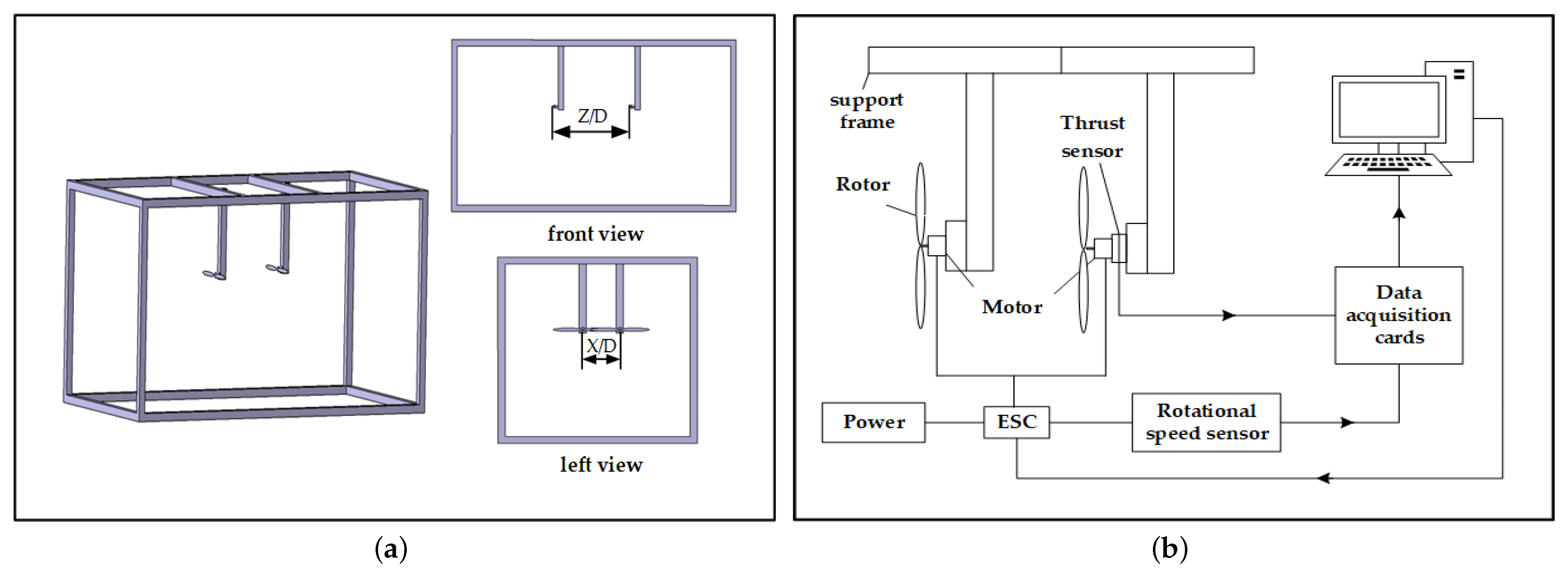
Compared to a single-rotor system, when interference occurs between two rotors, part of the bottom rotor operates within the wake of the top rotor, significantly degrading its aerodynamic performance. However, the aerodynamic performance of the top rotor is almost unaffected by rotor interference [37]. Therefore, in this experiment, only the aerodynamic performance of the bottom rotor, which is more significantly impacted by the wake, was measured. Figure 3a shows a schematic diagram of the test bench structure. This study focuses on analyzing the aerodynamic interference of the top rotor’s wake on the performance of the bottom rotor at various lateral and axial separations. To describe the relationship between rotor separation and rotor diameter, the lateral and axial separations are expressed as multiples of the rotor diameter. The lateral separation, defined as X/D, refers to the center-to-center distance between the two rotor hubs, while the axial separation, defined as Z/D, refers to the parallel distance between the horizontal planes of the two rotors. A schematic diagram of the experimental measuring device is shown in Figure 3b. The test system primarily consists of a rotor power system, rotor control system, sensor system, data acquisition system, and support structure. The power system comprises a DC power supply, an electronic speed controller (ESC), and a brushless DC motor, which together provide the necessary power to achieve the required rotor rotational speed for the tests. During the experiments, the DC power supply is set to 12.6 V, with the ESC model being the Hobbywing XRotor Pro, and the motor model being Sunnysky X2216, which drives the rotor’s rotation. The rotor control system is composed mainly of a host computer and a microcontroller board. Pulse-width modulation (PWM) parameters are input via the host computer, and upon receiving the PWM signal, the ESC adjusts the pulse duty cycle to regulate the average DC voltage supplied to the brushless motor, thereby controlling the rotor rotational speed. In the experiment, both rotors rotate in the same direction, with the ESC ensuring consistent rotor speeds. The sensor system is employed to collect and display experimental parameters in real time, including rotor thrust, rotor rotational speed, input voltage, and current. Rotor speed is primarily measured using a tachometer sensor connected to the brushless motor, which detects voltage variations on the motor leads and outputs corresponding speed signals. The data acquisition system records and stores the collected data for subsequent analysis. The force sensor used in the experiment has an accuracy of 0.05% F.S., and can measure a maximum thrust of 300 N.

2.2. Propeller Geometry

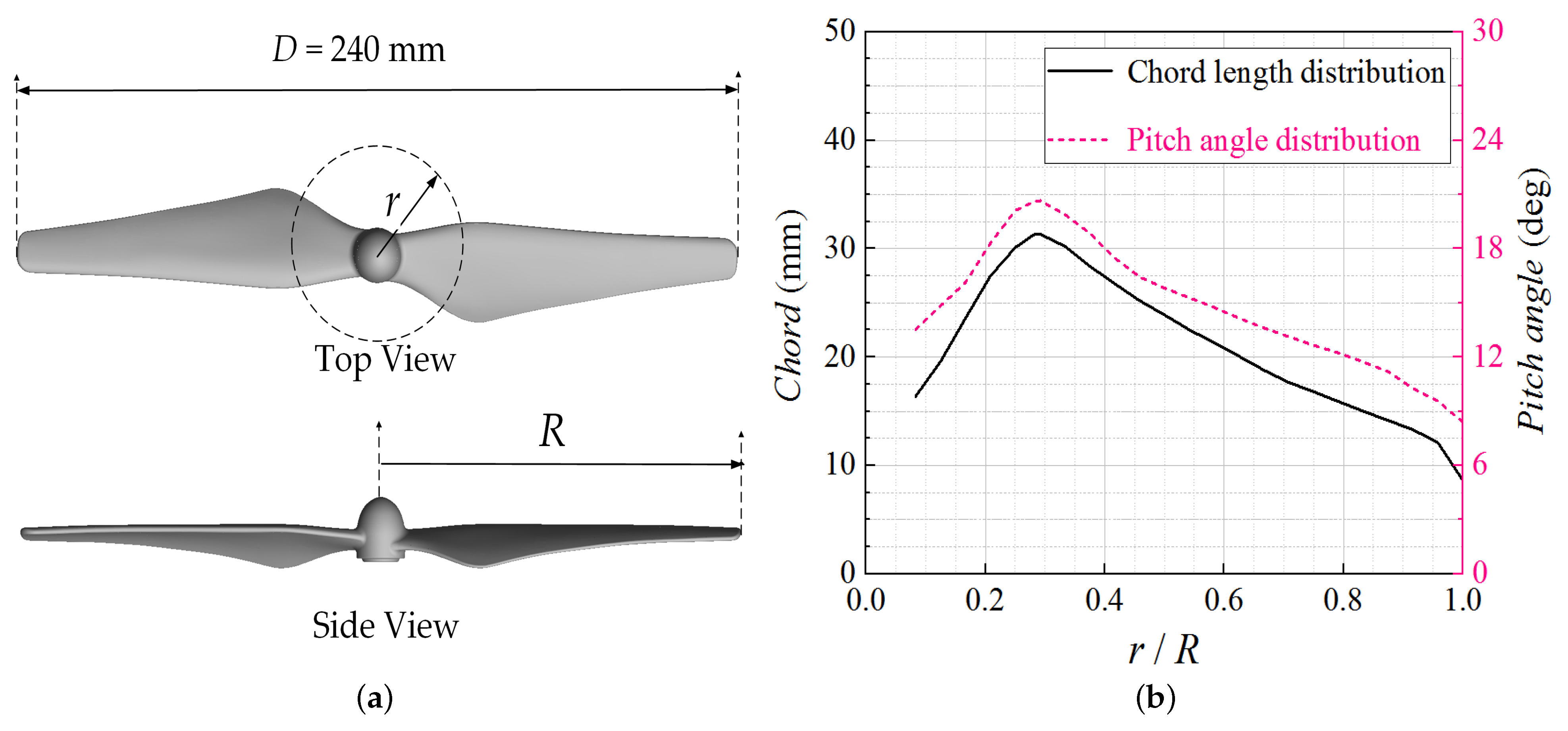
The 9450 self-locking propeller was selected for this study due to its high thrust capacity and excellent dynamic balance, making it widely used in DJI drones. The propeller consists of two blades, with a diameter of 9.4 inches (238.76 mm) and a pitch of 5.0 inches (12.70 cm). The weight of each propeller is approximately 23 g. The rotor’s geometric parameters and distribution of the rotor pitch angle and chord length are depicted in Figure 4. Significant variations in chord length and pitch angle are observed along the radial direction, with both reaching their maximum near 29% of the relative radius. The maximum and average pitch angles are 19.04° and 12.75°, respectively, while the maximum and average chord lengths are 6.06 cm and 2.00 cm, respectively.

2.3. Test Conditions and Parameter Definition

The test conditions primarily involve varying the lateral separation (X/D), axial separation (Z/D), and incoming wind speed. The range of parameter values used in the experiment is presented in Table 1.
The thrust of the bottom rotor was measured at various lateral and axial separations, and subsequently, calculated as a thrust coefficient. The formula for the thrust coefficient is presented in Equation (1). The experimental data were used to assess the impact of the top rotor’s wake on the performance of the bottom rotor under varying rotor speeds, lateral and axial separations, and flight speeds.
C T = T 1 2 ρ A Ω R 2
where T is the thrust in N; A is the rotor paddle disk area in m2; ρ is the fluid density in kg/m3; R is the rotor radius in m; and Ω is the rotor rotational speed in RPM.

3. Numerical Approach

3.1. CFD Methodology

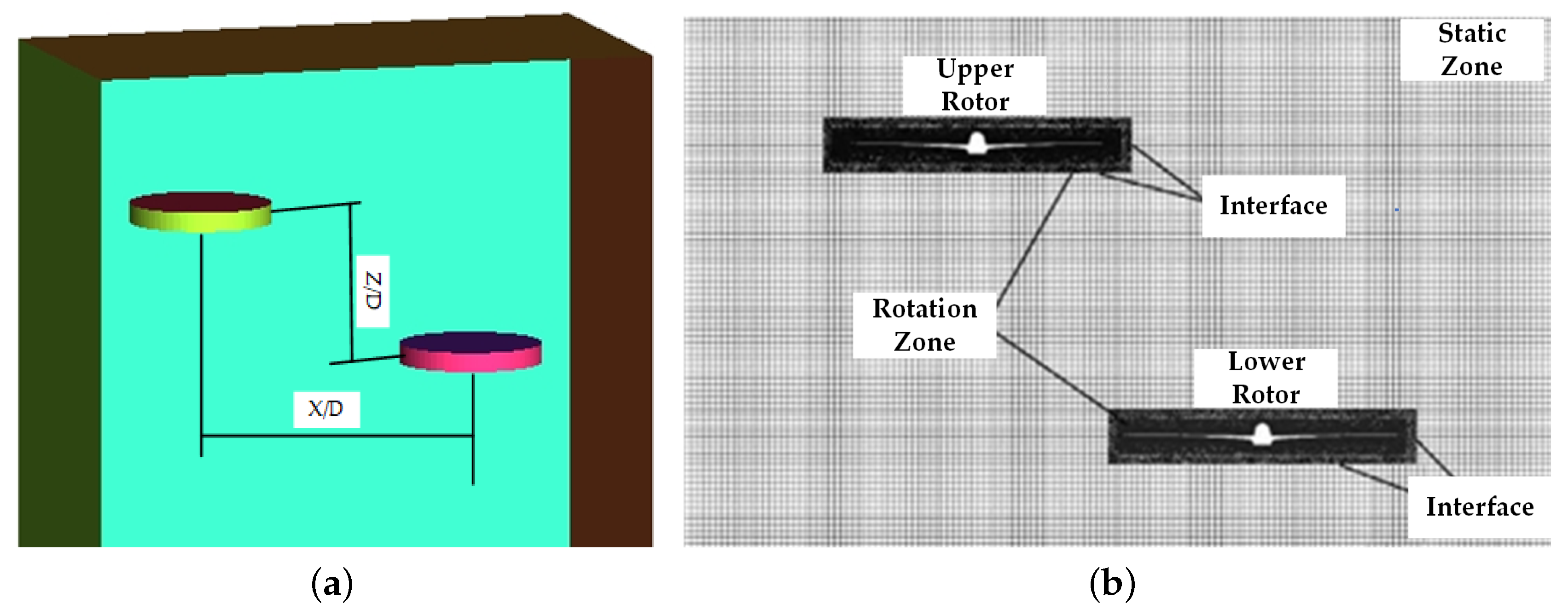
The simulation of the two-rotor velocity flow field employs the multiple reference frame (MRF) method, which divides the computational domain into a rotating domain, encompassing the rotor, and an external stationary domain. The dimensions of the stationary domain are adjusted according to variations in the lateral and axial separation between the rotors. The rotating domain has a diameter of 1.1D and a thickness of approximately 0.13D. While the grid in the rotating domain remains fixed, a rotating coordinate system is applied, accounting for Coriolis and centripetal forces, to compute steady-state conditions. The stationary domain is calculated based on inertial reference coordinates, and flow parameters are exchanged between the rotating and stationary domains through an interface boundary. When adjustments to the lateral (X/D) and axial (Z/D) separations between the two rotors are required to assess the impact of spatial positioning on rotor aerodynamic performance, the top rotor is fixed, and the relative position of the bottom rotor is shifted to update the grid for computations under new operating conditions.

3.2. Meshing

The computational domain flow field is divided using a mixed structured–unstructured mesh. A structured mesh is applied to the stationary domain, while unstructured meshes are used for the two rotating domains, each consisting of 2.9 million elements. The mesh of the rotor’s vertical cross-section is illustrated in Figure 5. To accurately capture the rotor flow field characteristics, mesh refinement is applied around the rotor wall and its leading and trailing edges. Additionally, a prismatic grid is used on the rotor surface with 10 boundary layer divisions, ensuring that the first grid layer corresponds to a y+ value near 1.

3.3. CFD Validation

Figure 6 presents the variation in thrust with rotor rotational speed of an isolated rotor, based on both experimental data and CFD simulations. The results are compared with data from Ambar [36] for the same model to validate the experimental and numerical methods. In order to ensure consistency with the test conditions in Ref. [36], the hovering test of the single rotor used for verification was carried out outside the wind tunnel. The rotational speed from the reference is not exactly the same as the present experimental rotational speed, so a 10% error band is drawn based on the experimental data of present study. The experimental thrust results show minimal differences and are in good agreement with the reference data. The thrust at 2000, 5000, and 8000 RPM was obtained using CFD with relative errors of 4%, 7%, and 11%, respectively. Thus, the CFD methodology is adequate to explore the rotor’s performance.

4. Result and Analysis

4.1. The Effect of Aerodynamic Interference During Hover Flight

Figure 7 presents the experimental results of the thrust coefficient for the bottom rotor as a function of rotor rotational speed, with a lateral separation of X = 0D and an axial separation of Z = 1D. It can be observed that the thrust coefficient of the bottom rotor increases progressively with rotor rotational speed, and then, stabilizes across various lateral and axial separations. This behavior occurs because, as the rotor rotational speed increases, the viscous effects of the fluid on the rotor diminish while the inertial effects become more pronounced, enhancing rotor performance. Consequently, when the thrust coefficient is reduced due to wake interference, the aerodynamic performance can be improved by increasing the rotor rotational speed. The thrust coefficient of the isolated rotor, also shown in the figure, indicates that, at an axial separation of Z = 1.0D and a lateral separation of X = 1.0D, the bottom rotor’s thrust coefficient at low-to-moderate rotational speeds is higher than that of the isolated rotor. This phenomenon may be attributed to the complex tip vortices and induced velocities generated by the upstream rotor, which create favorable aerodynamic conditions around the downstream rotor within this range of separation and rotor speed, thereby improving its aerodynamic performance. Additionally, the thrust coefficients of the top rotor during hover conditions with two rotors were obtained through numerical simulation. These results show that the thrust coefficient of the top rotor remains nearly unchanged across different rotor separations, demonstrating that the separation between the rotors has minimal impact on the thrust coefficient of the top rotor.
In the following analysis, C T / C T , s i n g l e represents the extent to which the wake affects the rotor thrust coefficient. This ratio compares the thrust coefficient of the rotor influenced by the wake with that of an isolated rotor operating under the same rotational speed and flight conditions. A smaller value indicates a greater reduction in aerodynamic performance, while a value closer to 1 suggests minimal influence of the top rotor’s wake on the bottom rotor. Figure 8 illustrates the variation in the bottom rotor thrust coefficient ratio, C T / C T , s i n g l e , with changes in lateral and axial separations at fixed rotational speeds of 5000 RPM and 8000 RPM. It is evident that when the lateral and axial separations are small, the bottom rotor is significantly impacted by the wake from the top rotor. At 5000 RPM, for a lateral separation of X = 0D and an axial separation of 1D Z 3D, the thrust coefficient of the bottom rotor decreases by nearly 45%. Furthermore, with a fixed axial separation, the bottom rotor thrust coefficient increases as lateral separation grows, although this rate of increase diminishes with greater axial separations. This behavior arises from the varying degree of wake interference, which weakens as axial separation increases. In Figure 8a, when the axial separation is Z = 1D, increasing the lateral separation from 0D to 1D leads to an 84% increase in the bottom rotor thrust coefficient. For axial separations of Z = 3D, 5D, and 7.5D, the thrust coefficient increases by 77%, 51%, and 26%, respectively. Additionally, at a lateral separation of X = 0D, the thrust coefficient increases with axial separation. However, at X = 1D, the opposite occurs, with the thrust coefficient decreasing as axial separation increases. When the axial separation reaches Z = 11D, the maximum relative deviation in the thrust coefficient due to changes in lateral separation is only 3.56%, indicating minimal sensitivity to lateral separation. This is because, at this distance, the wake from the top rotor has developed to the point where velocity becomes uniform across the lateral range, though some disturbance persists, still affecting the bottom rotor’s aerodynamic performance. Consequently, the bottom rotor thrust coefficient remains around 85%.
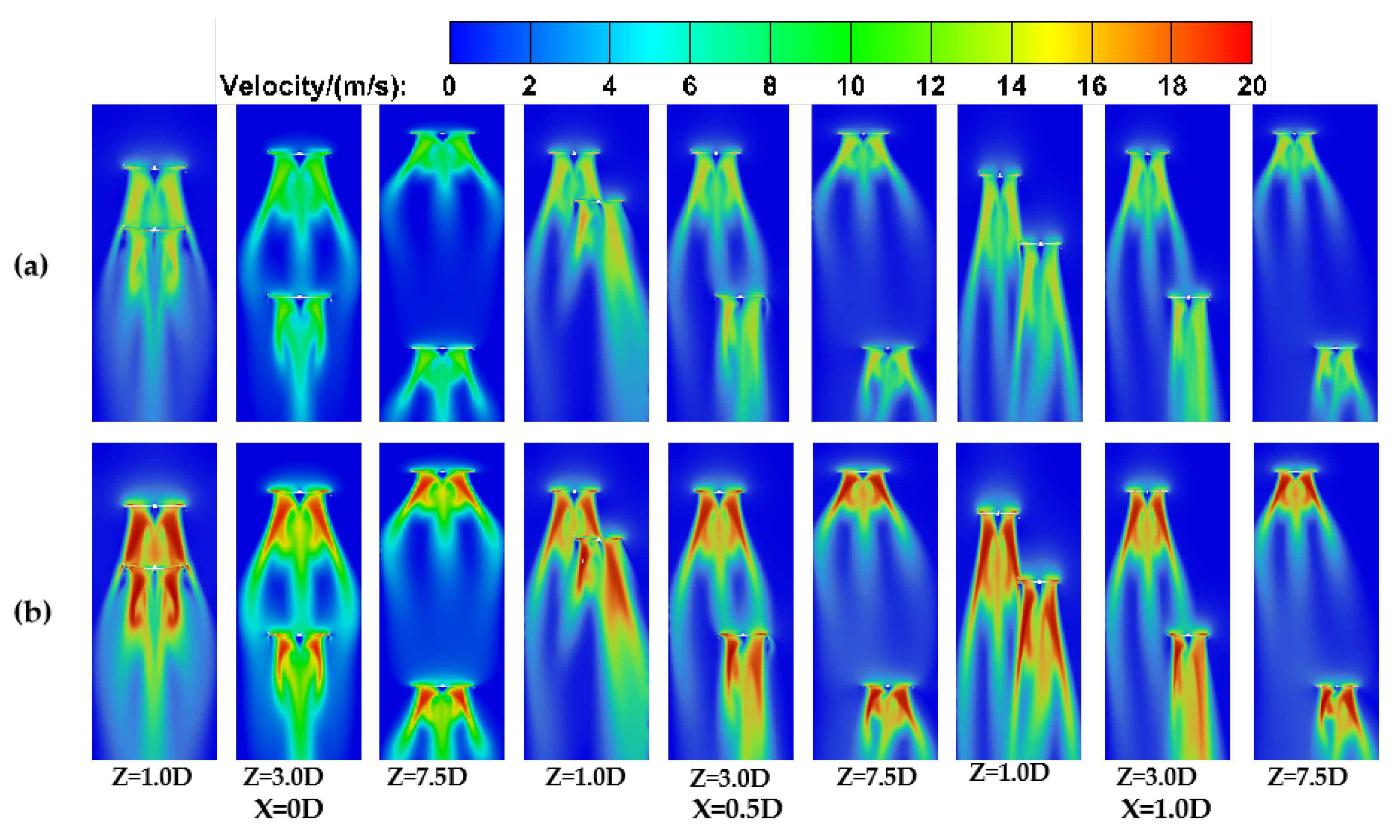
In order to analyze the interference of the wake flow field of the two rotors at different separations, the velocity fields of the two rotors at the cross-section were obtained and compared through numerical simulations. As can be seen in Figure 9, during hovering, the wake field of the top rotor is basically unaffected, while the bottom rotor is more obviously affected by the wake of the top rotor. From the velocity contour of the top rotor, it is evident that two high-speed airflows are generated beneath the blades on both sides of the rotor, which spread radially outward. Simultaneously, a lower-speed region forms vertically downward in the central area of the rotor due to the induction of the high-speed airflows on both sides. The velocity flow field of the bottom rotor differs from that of the top rotor due to the interference from the top rotor’s wake. Additionally, a comparison of the mid-section velocity fields at rotor speeds of 5000 RPM and 8000 RPM reveals that with increased rotor rotational speed, the wake velocity increases, although the shape of the wake field remains unchanged. When the lateral separation is X = 0D, the bottom rotor is positioned directly beneath the top rotor. The flow field distribution of the two rotors remains symmetrical. At Z = 1D, the wake from the top rotor is nearly fully absorbed by the bottom rotor, leading to an increase in velocity within the high-speed region of the two-rotor wake. Meanwhile, the outward diffusion of the bottom rotor’s wake is constrained by the influence of the top rotor’s wake. As the axial separation between the two rotors increases further, the speed of the high-speed region of the wake gradually decreases, and the wake of the bottom rotor starts to detach from the influence of the top rotor’s wake and spreads outward. When the axial separation between the rotors is Z = 7.5D, the separation is sufficient such that the bottom rotor’s wake is minimally affected by the top rotor’s wake. When there is lateral separation between the top and bottom rotors, the symmetry of the bottom rotor’s flow field is disrupted, and the wake field exhibits asymmetric characteristics. This asymmetry is primarily due to the non-uniformity of the upstream inflow to the blades of the bottom rotor. For a lateral separation of X = 0.5D and an axial separation of Z = 1D, the bottom rotor is displaced to the right relative to the top rotor, which enhances the airflow speed on the left side of the bottom rotor but hinders the development of the left-side wake. Conversely, the wake speed on the right side of the bottom rotor is slower, but its development distance is greater than that of the left side. As the lateral separation of the two rotors transitions from 0 to 1D, the interference between the rotor flow fields decreases progressively. When X = 1D, the mutual interference between the rotors weakens, and the wake symmetry improves. Thus, it is observed that the rotor is sensitive to the airflow entering its blades, which can significantly impact its wake field.

4.2. The Effect of Aerodynamic Interference During Vertical Flight

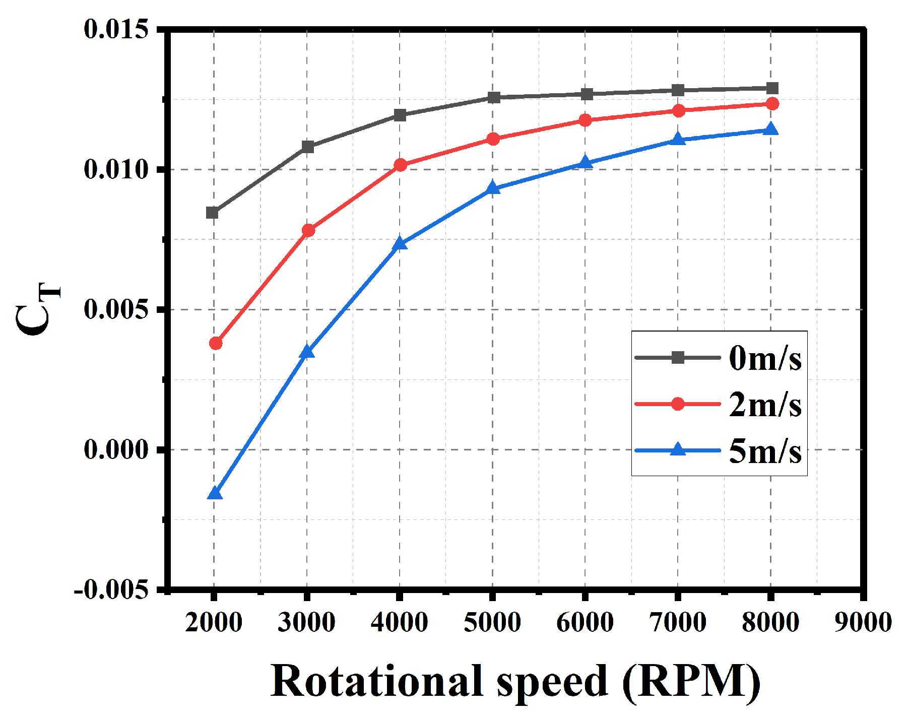
Figure 10 shows the variation in thrust coefficient for an isolated rotor at different flight speeds. When the flight speed remains constant, the thrust coefficient increases rapidly with rotor rotational speed before stabilizing. Conversely, when the rotor rotational speed is held constant, an increase in vertical flight speed results in a decrease in thrust coefficient. Additionally, at a high vertical flight speed of 5 m/s and a low rotor rotational speed of 2000 RPM, the thrust coefficient becomes negative, meaning the rotor generates drag instead of thrust, with the force acting opposite to the direction of flight. Therefore, at high vertical flight speeds, increasing rotor rotational speed is necessary to maintain the rotor’s aerodynamic performance.
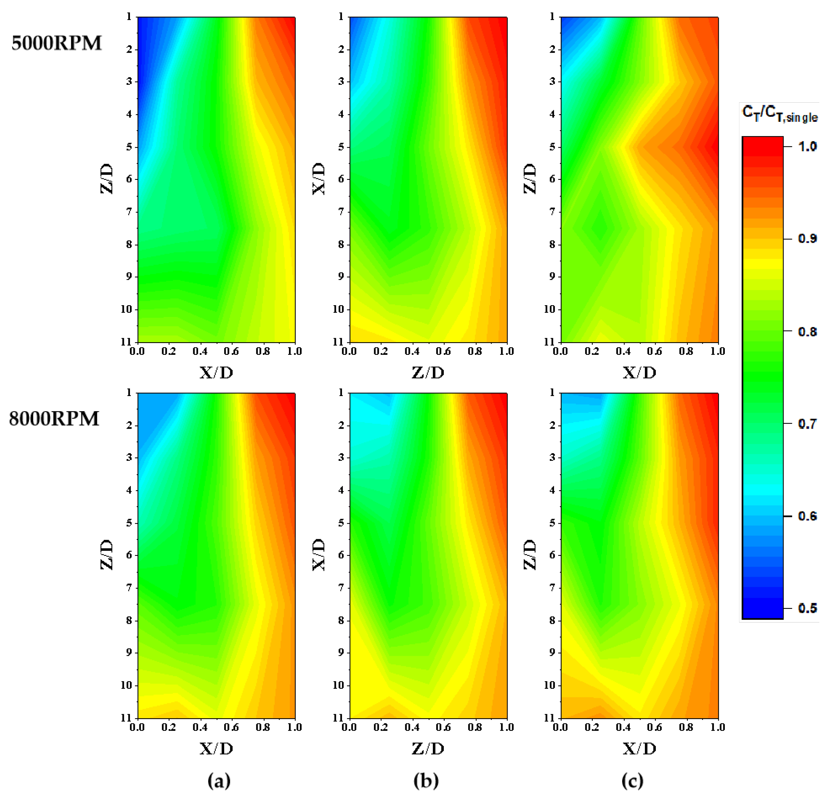
Figure 11 illustrates the variation in C T / C T , s i n g l e with lateral and axial separation for different vertical flight speeds, at rotor speeds of 5000 RPM and 8000 RPM. It is observed that in vertical flight (2 m/s and 5 m/s), the wake interference region of the top rotor resembles that in the hovering state (v = 0 m/s). A significant region of aerodynamic interference is found near a lateral separation of X = 0D, where the thrust coefficient is more severely affected. This region shrinks as the flight speed increases. Conversely, at lateral separations close to X = 1D, the aerodynamic interference between the rotors has a smaller impact on the thrust coefficient, and this region expands with increasing flight speed. These results indicate that the aerodynamic interference between the two rotors during vertical flight is closely related to the vertical flight speed.
Figure 12 presents the variation in the thrust coefficient ratio, C T / C T , s i n g l e , of the bottom rotor with lateral separation at different vertical flight speeds. When the axial separation is between 1D and 3D and the lateral separation is X = 0D, the bottom rotor experiences significant disturbance from the wake of the top rotor, resulting in a substantial decrease in thrust coefficient. At 5000 RPM, the thrust coefficient of the bottom rotor decreases by approximately 46% at a flight speed of 2 m/s and by about 50% at 5 m/s, when the axial separation is Z = 1D and the lateral separation is X = 0D. With the same axial separation (Z = 1D) and a lateral separation of X = 1D, the thrust coefficient decreases by 5% at 2 m/s and by approximately 13% at 5 m/s. Moreover, at various axial separations, the thrust coefficient reaches its maximum at X = 1D as the lateral separation increases. At a rotor rotational speed of 5000 RPM and a lateral separation of X = 1D, the thrust coefficient remains above 87% of that of the isolated rotor at a flight speed of 2 m/s and above 83% at 5 m/s. At 8000 RPM, the thrust coefficient is maintained above 89% of the isolated rotor at both 2 m/s and 5 m/s. As the axial separation increases to Z = 11D, the effect of lateral separation on the bottom rotor’s thrust coefficient is significantly reduced, and the variation in thrust coefficient with lateral separation becomes less pronounced. At 5000 RPM and a flight speed of 2 m/s, the thrust coefficient remains above 82% of the isolated rotor, while at 5 m/s, it remains above 74%. At 8000 RPM, the thrust coefficient exceeds 85% of the isolated rotor at both 2 m/s and 5 m/s. In summary, as flight speed increases, the thrust coefficient of the bottom rotor decreases more significantly under wake-influenced flight conditions. This can be attributed to the interaction between the top rotor’s wake and the vertical flight airflow, leading to greater disturbance and a further reduction in aerodynamic performance. When rotor rotational speed increases from 5000 RPM to 8000 RPM, the trend in thrust coefficient remains similar, though the impact of flight speed on the bottom rotor’s thrust coefficient is reduced, indicating improved aerodynamic performance at higher speeds. During vertical flight, when axial separation is small, the lateral separation should be set to at least one rotor diameter, and when the lateral separation is X = 0D, the axial separation should be at least 11 rotor diameters.
Figure 13 presents the mid-section velocity flow field of the two rotors at different separations during vertical flight speeds of 2 m/s and 5 m/s. In Figure 13a,b, when the vertical flight speed is 2 m/s, the wake flow shape shows minimal variation compared to the hovering state. However, at a rotor rotational speed of 5000 RPM and lateral separation of X = 0D with an axial separation of Z = 1D, the low-speed airflow at the outer region of the wake disappears, while the high-speed airflow region remains largely unchanged. In Figure 13c, when the flight speed increases to 5 m/s and the rotor rotational speed remains at 5000 RPM, significant changes occur in the rotor wake. The wake is compressed by the relative airflow moving opposite to the rotor’s flight direction, causing the high-speed flow on both sides of the blades to merge with the low-speed wake at the rotor center. This results in a columnar development of the wake in the axial direction, while its lateral expansion is constrained, reducing the lateral influence. Additionally, at X = 0D, the symmetry of the mid-section velocity field is disrupted, and the bottom rotor wake becomes disordered due to weaker wake strength and interference with surrounding air caused by the higher flight speed. Compared to Figure 13c, where the flight speed remains at 5 m/s but the rotor rotational speed increases to 8000 RPM, in Figure 13d the wake characteristics start to recover. The wake reestablishes its division into two high-speed streams and a central low-speed zone, though it is notably contracted compared to Figure 13b, and the low-speed wake gradually disappears. Furthermore, under the same rotor rotational speed conditions, the wake velocity slightly increases with higher flight speeds. This is attributed to the combined effect of induced flow and the relative incoming flow accelerating the velocity above the rotor, thereby enhancing the wake speed below the rotor.

4.3. The Effect of Aerodynamic Interference During Horizontal Flight

The steady forward flight of a real UAV is performed with a certain angle of attack in fact. The results of horizontal flight in this section are only considered in an ideal condition with zero angle of attack, which could provide a reference for actual horizontal flight.
Figure 14 presents the thrust coefficient curves of an isolated rotor at various horizontal flight speeds. It can be observed that for a given rotor rotational speed an increase in flight speed leads to a higher thrust coefficient. This is because higher flight speeds increase the dynamic pressure entering the rotor disk, which, in turn, increases the pressure differential between the upper and lower surfaces of the rotor, resulting in a greater thrust coefficient. However, the magnitude of this effect varies with rotor rotational speed. At 2000 RPM, increasing the flight speed from 0 m/s to 15 m/s results in a thrust coefficient increase of 0.02, representing a 2.78 times rise. In contrast, at 8000 RPM, the thrust coefficient increases by only 0.003, a 29% increase. During hovering, the thrust coefficient rises with increasing rotor rotational speed before stabilizing. However, for horizontal flight speeds between 2 and 15 m/s, the thrust coefficient initially decreases rapidly as rotor rotational speed increases, and then, stabilizes.
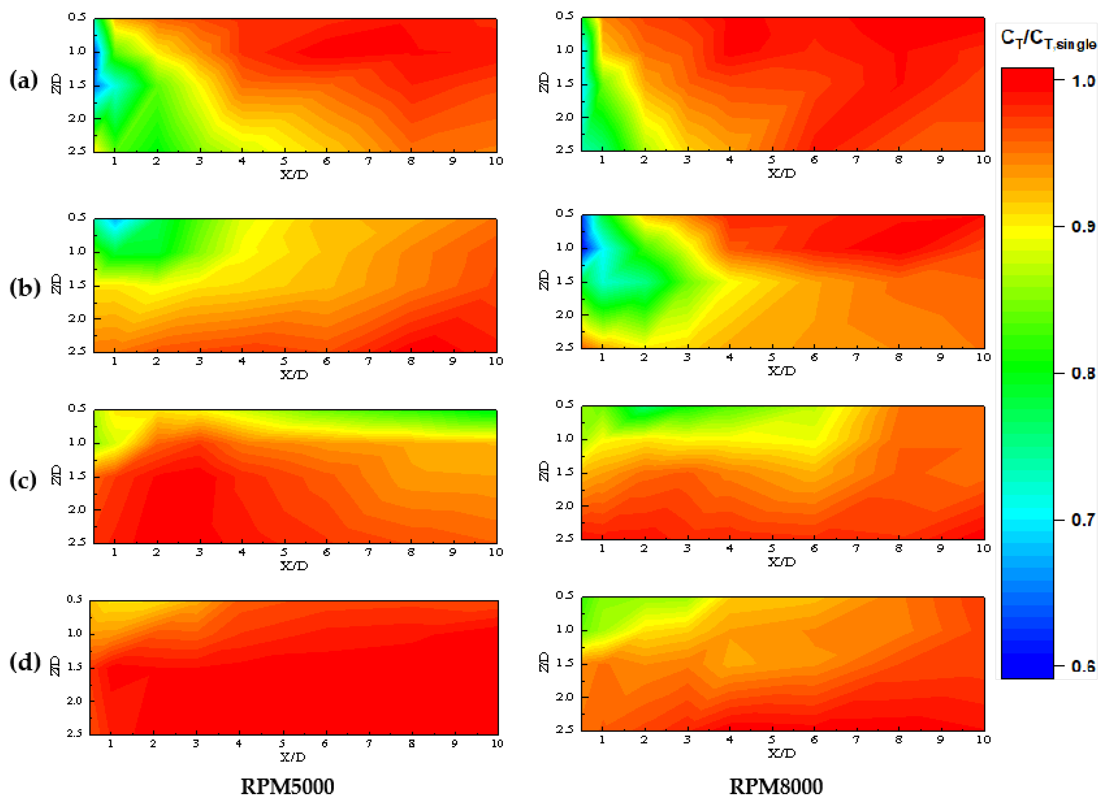
Figure 15 shows the variation in C T / C T , s i n g l e with lateral and axial separation for the bottom rotor at different horizontal speeds when the rotor rotational speed is 5000 RPM and 8000 RPM. It is evident that when the rotor operates within the wake flow of the top rotor, its thrust coefficient decreases, indicating a significant impact of the wake on rotor aerodynamic performance. As shown in Figure 15a, at a horizontal flight speed of 2 m/s, a rotor rotational speed of 5000 RPM, and an axial distance of Z = 2.5D, the thrust coefficient of the bottom rotor decreases significantly within the lateral range of 0.5D X 5 D. When the rotor rotational speed increases to 8000 RPM, this lateral range narrows to 0.5D X 3D, suggesting that the lateral extent of wake influence decreases as the rotor rotational speed increases. As the horizontal flight speed increases from 2 m/s to 10 m/s, while maintaining the same rotor rotational speed, it can be observed that the region severely affected by the wake expands laterally but contracts axially. Moreover, at a flight speed of 15 m/s, the wake-affected region is substantially reduced. This reduction is likely due to the high-speed relative airflow limiting the wake’s development over long distances, thereby shrinking the wake influence area more than at lower flight speeds.
Figure 16 illustrates the variation in the thrust coefficient ratio C T / C T , s i n g l e of the bottom rotor at different horizontal flight speeds. Taking 5000 RPM as an example, the influence of the top rotor wake changes with horizontal flight speed. When the axial separation is Z = 0.5D, the two rotors are closely spaced. At a flight speed of 2 m/s, the thrust coefficient of the bottom rotor decreases by approximately 27% at a lateral separation of X = 0.5D. At 5 m/s, the thrust coefficient decreases by about 32% within the range of 0.5D X 2D. At 10 m/s, the thrust coefficient decreases by nearly 20% at X = 10D. Only at a flight speed of 15 m/s does the thrust coefficient of the bottom rotor remain above 90% of that of the isolated rotor across the entire lateral separation range. For Z = 1.5D and a flight speed of 2 m/s, the most significant decrease in thrust coefficient occurs at X = 0.5D, with a reduction of approximately 36%. When the flight speed reaches or exceeds 5 m/s, the thrust coefficient remains above 90% of the isolated rotor within the range of 1D X 10D. At Z = 2.5D, where the axial separation between the two rotors is relatively large, the thrust coefficient decreases by nearly 20% in the lateral separation range of 1D X 3D at 2 m/s. When the flight speed is 5 m/s or higher, the thrust coefficient remains above 95% of the isolated rotor across the entire lateral separation range. As the rotor rotational speed increases from 5000 RPM to 8000 RPM, wake interference intensifies, leading to a more pronounced decrease in the thrust coefficient of the bottom rotor with lateral separation. This is attributed to the increased wake intensity of the top rotor at higher rotational speeds, which amplifies its impact on the downstream region. At 8000 RPM and Z = 0.5D, the lateral range in which the thrust coefficient decreases expands as flight speed increases. At 5 m/s, the thrust coefficient drops by approximately 40% at X = 0.5D. For Z = 1.5D, at flight speeds of 2 m/s and 5 m/s, the thrust coefficient decreases by about 30% in the region of X ≤ 1D, while at 10 m/s and 15 m/s, it remains between 90% and 95% of the isolated rotor. For Z = 2.5D, at a flight speed of 2 m/s, the thrust coefficient decreases by about 27% at X = 0.5D, while at 5 m/s, it decreases by about 10% across the entire lateral separation range. At 10 m/s and 15 m/s, the reduction in thrust coefficient does not exceed 5% across the entire lateral separation range.
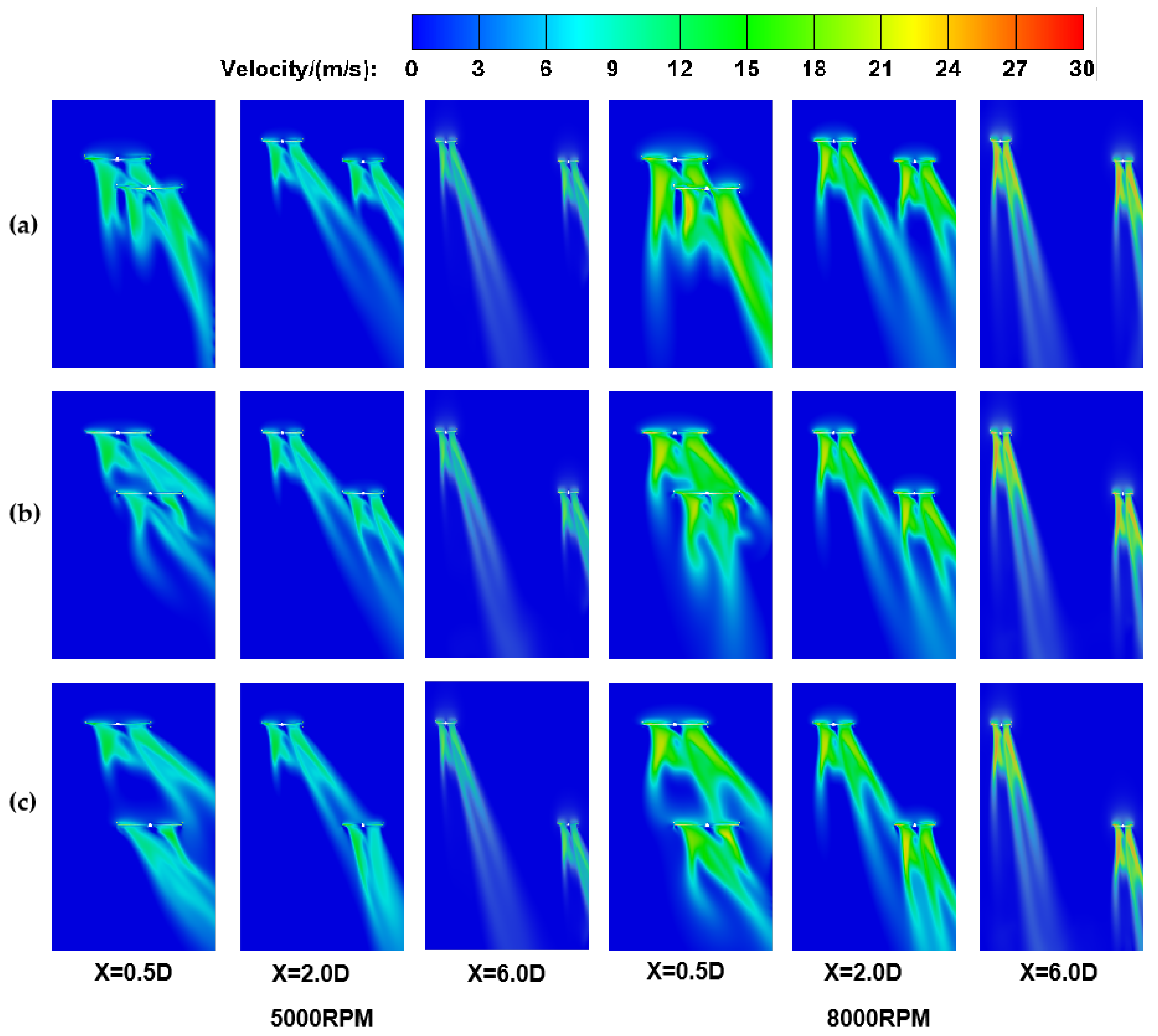
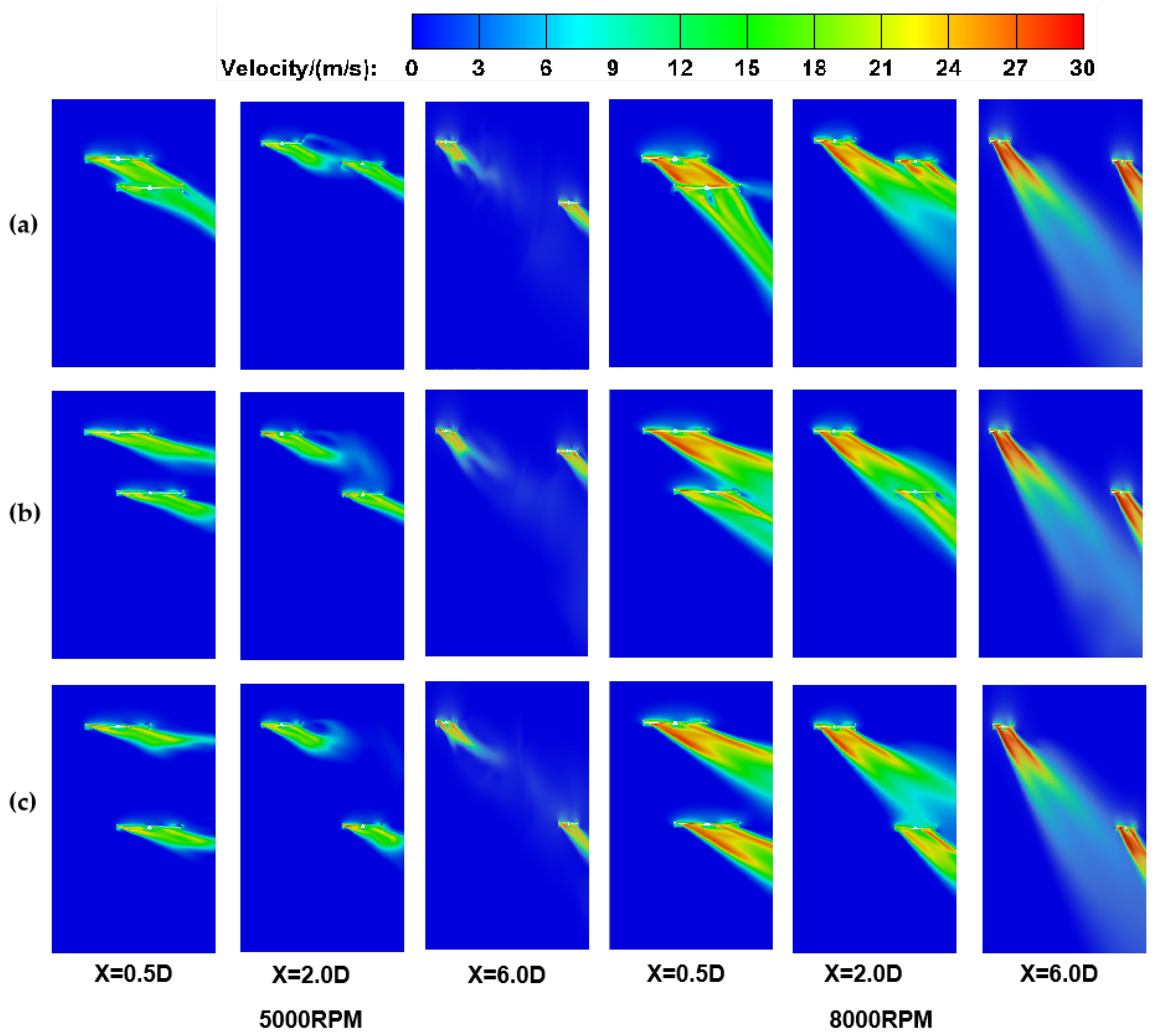
Figure 17 and Figure 18 illustrate the velocity field of the mid-section of the two rotors at horizontal flight speeds of 2 m/s and 10 m/s. It can be observed that as the rotors advance, their wakes tilt rearward, with the inclination angle increasing as the horizontal flight speed rises. This occurs because during horizontal flight the rotor is influenced not only by the vertically induced downward airflow but also by the horizontally opposing relative airflow. The faster the horizontal flight speed, the greater the relative airflow’s impact on the rotor, resulting in a backward-tilted wake field. Moreover, as the wake tilt increases, its influence extends farther horizontally to the bottom rotor, while its axial influence diminishes. For instance, at a horizontal flight speed of 2 m/s and a rotor rotational speed of 5000 RPM, with rotor separations of X = 2D and Z = 2.5D, the wake from the top rotor is drawn into the plane of the bottom rotor’s disk. Conversely, at a horizontal flight speed of 10 m/s, the top rotor’s wake has negligible impact on the bottom rotor. At a horizontal flight speed of 2 m/s, the wake develops over a shorter distance on the left half of the rotor near the blade tip, while at the rotor center, the airflow merges with the airflow on the right half, leading to a longer wake development distance. Comparing the velocity fields at 2 m/s and 10 m/s, it becomes evident that higher horizontal flight speeds result in higher wake velocities. This is because at higher speeds the relative speed between the rotor and the oncoming wind increases, enhancing the rotor’s thrust and induced flow. Consequently, the rotor’s leading edge experiences greater dynamic pressure, producing a stronger wake field, with faster downward-accelerated airflow and a more concentrated wake. Additionally, with a rotor rotational speed of 5000 RPM and a lateral separation of X = 6D, a comparison between the wakes at 2 m/s and 10 m/s shows that at 10 m/s, the wake dissipates over a shorter distance due to interaction with the surrounding airflow, reducing its lateral influence. However, when the rotor rotational speed increases from 5000 RPM to 8000 RPM, the dissipated wake reappears. Therefore, it can be concluded that the combined effects of horizontal flight speed and rotor rotational speed must be considered when evaluating the influence of rotor wakes during forward flight.

5. Conclusions

This study investigates the aerodynamic interference between UAV rotors and the effects of various wake separations during low-altitude formation flight, using wind tunnel tests and numerical simulations. Since the flow field and aerodynamic parameters of the top rotor remain largely unaffected by interference, the focus is on the aerodynamic performance of the bottom rotor, which is significantly impacted by the wake. The interference between the rotors is examined in hover flight, vertical flight, and horizontal flight. The following conclusions are drawn.
(1)
Hover flight: When the lateral separation is X = 0D, and the axial separation is between 1.0D and 3.0D, the aerodynamic performance of the bottom rotor is significantly reduced, with the thrust coefficient decreasing by nearly 45%. As the lateral and axial separations increase, the bottom rotor gradually moves out of the severe interference region, leading to a gradual rise in its thrust coefficient. While the axial separation remains constant, the thrust coefficient continues to increase with lateral separation, although the rate of increase diminishes as the axial separation grows. The simulation results indicate that when the lateral separation between the two rotors is X = 0D, the velocity field of the rotors exhibits good symmetry. However, when a lateral separation exists, the flow field around the bottom rotor becomes distinctly asymmetric. The inner wake of the rotor features higher velocity but a shorter development distance, while the outer wake has a lower velocity but a longer development distance. The wake flow field of the bottom rotor is highly sensitive to changes in the inflow over the upper surface of the rotor disk. In hovering conditions, it is recommended to maintain a lateral separation of X ≥ 1D or an axial separation of Z 11D.
(2)
Vertical flight: When the rotor separation is small, the thrust coefficient decreases the most at the lateral separation X = 0D. For example, the thrust coefficient at the axial separation Z = 1D is reduced by nearly 50%. When the bottom rotor is affected by the wake, the decrease in the thrust coefficient becomes significant as the flight speed increases. As the axial separation increases, the rotor’s thrust coefficient at X = 1D is the largest. When the rotor is rotating at 5000 RPM, and the flight speed is 2 m/s, the rotor’s thrust coefficient can reach 87% of the isolated rotor’s thrust coefficient, and at 5 m/s, it can remain above 83%. In addition, the flow field pattern of the rotor’s cross-section speed is affected by the flight speed and rotor rotational speed. For a rotor with a speed of 5000 RPM and a flight speed of 2 m/s, only the low-speed airflow on the outer periphery of the wake is affected and gradually disappears. When the flight speed increases to 5 m/s, the rotor wake shows a tendency to shrink. It is recommended that when the axial separation is small, the lateral separation should be greater than or equal to 1D; when the lateral separation is X = 0D, the axial separation should be greater than or equal to 11D. In order to avoid a significant decrease in the thrust coefficient due to high-speed flight, the flight speed should be controlled appropriately.
(3)
Horizontal flight: The wake from the top rotor significantly affects the thrust coefficient of the bottom rotor, even at larger lateral separations. The extent of this influence is closely related to the rotor’s RPM and horizontal flight speed. The experimental results indicate that under wake interference, the thrust coefficient can decrease by up to 40%. For horizontal flight at a speed of 2 m/s, it is recommended that the lateral separation between the rotors be X ≥ 4.0D. At flight speeds of 5 m/s or higher and axial separation of Z = 1.5D, the rotor thrust coefficient remains above 90% of the isolated rotor’s thrust coefficient. When Z = 2.5D, the thrust coefficient stays above 95% of the isolated rotor’s thrust coefficient across the entire lateral separation. The velocity field analysis shows that during horizontal flight, the rotor wake inclines toward the side and rear. As the flight speed increases, the angle of inclination of the wake also increases, concentrating the flow region and expanding the range of lateral interference. Additionally, at higher flight speeds with lower rotor RPM, the wake intensity decreases, and the wake development distance shortens. Based on both experimental and simulation results, it is recommended to increase the lateral separation to reduce wake interference during high-speed horizontal flight while the axial separation can be appropriately reduced.

Author Contributions

Conceptualization, C.L., Z.W. and B.L.; methodology, C.L., Z.W. and Z.Z.; software, C.L. and B.L.; validation, Z.Z., B.L. and Z.S.; formal analysis, B.L. and Y.W.; investigation, B.L., Z.S. and Y.W.; resources, C.L., Z.Z. and Z.S.; data curation, Y.W.; writing—original draft preparation, B.L.; writing—review and editing, B.L. and C.L.; visualization, B.L. and C.L.; supervision, C.L., Z.Z. and Z.S.; project administration, B.L. and Y.W.; funding acquisition, C.L. All authors have read and agreed to the published version of the manuscript.

Funding

This research was funded by Multi-input youth project of the Tianjin Natural Science Foundation (C.L., No. 23JCQNJC00170), Fundamental Research Funding Project for Central Universities of Civil Aviation University of China (C.L., No. KJZ53420230006).

Data Availability Statement

The data presented in this study are available on request from the first author.

Conflicts of Interest

The authors declare no conflicts of interest.

References

  1. Gillis, D.; Petri, M.; Pratelli, A.; Semanjski, I.; Semanjski, S. Urban Air Mobility: A State of Art Analysis. In Proceedings of the Computational Science and Its Applications—ICCSA 2021, Cagliari, Italy, 13–16 September 2021; Gervasi, O., Murgante, B., Misra, S., Garau, C., Blečić, I., Taniar, D., Apduhan, B.O., Rocha, A.M.A., Tarantino, E., Torre, C.M., Eds.; Springer: Cham, Switzerland, 2021; pp. 411–425. [Google Scholar]
  2. Pak, H.; Asmer, L.; Kokus, P.; Schuchardt, B.I.; End, A.; Meller, F.; Schweiger, K.; Torens, C.; Barzantny, C.; Becker, D.; et al. Can Urban Air Mobility become reality? Opportunities and challenges of UAM as innovative mode of transport and DLR contribution to ongoing research. Ceas Aeronaut. J. 2024, 1–31. [Google Scholar] [CrossRef]
  3. Archdeacon, J.L.; Iwai, N. Aerospace cognitive engineering laboratory (acelab) simulator for urban air mobility (uam) research and development. In Proceedings of the AIAA Aviation 2020 Forum, online, 15–19 June 2020; p. 3187. [Google Scholar]
  4. Koumoutsidi, A.; Pagoni, I.; Polydoropoulou, A. A new mobility era: Stakeholders’ insights regarding urban air mobility. Sustainability 2022, 14, 3128. [Google Scholar] [CrossRef]
  5. Kiesewetter, L.; Shakib, K.H.; Singh, P.; Rahman, M.; Khandelwal, B.; Kumar, S.; Shah, K. A holistic review of the current state of research on aircraft design concepts and consideration for advanced air mobility applications. Prog. Aerosp. Sci. 2023, 142, 100949. [Google Scholar]
  6. Wang, L.; Deng, X.; Gui, J.; Jiang, P.; Zeng, F.; Wan, S. A review of urban air mobility-enabled intelligent transportation systems: Mechanisms, applications and challenges. J. Syst. Archit. 2023, 141, 102902. [Google Scholar] [CrossRef]
  7. Phadke, A.; Medrano, F.A.; Chu, T.; Sekharan, C.N.; Starek, M.J. Modeling Wind and Obstacle Disturbances for Effective Performance Observations and Analysis of Resilience in UAV Swarms. Aerospace 2024, 11, 237. [Google Scholar] [CrossRef]
  8. Wang, Z.; Wang, T.; Li, T.; Mao, Z. Distributed observer-based close formation control for UAV swarm under outside disturbances and wake interferences. J. Frankl. Inst. 2024, 361, 106651. [Google Scholar] [CrossRef]
  9. Throneberry, G.; Hocut, C.; Abdelkefi, A. Multi-rotor wake propagation and flow development modeling: A review. Prog. Aerosp. Sci. 2021, 127, 100762. [Google Scholar] [CrossRef]
  10. Baculi, J.E.; Nguyen, N.T.; Okolo, W.; Xiong, J. Wake Vortex Effects Between Urban Air Mobility Aircraft. In Proceedings of the AIAA SciTech 2023 Forum, National Harbor, MD, USA, 23–27 January 2023; p. 1558. [Google Scholar]
  11. Wang, C.H.J.; Nathanael, J.C.; Ng, E.M.; Ng, B.F.; Low, K.H. Framework for the estimation of safe wake separation distance between same-track multi-rotor UAS. In Proceedings of the AIAA SciTech 2021 Forum, online, 11–15 January 2021; p. 0708. [Google Scholar]
  12. Sengupta, B.; Lee, Y.; Araghizadeh, M.; Myong, R.; Lee, H. Comparative Analysis of Direct Method and Fast Multipole Method for Multirotor Wake Dynamics. Int. J. Aeronaut. Space Sci. 2024, 25, 789–808. [Google Scholar] [CrossRef]
  13. Abras, J.; Hariharan, N.S.; Narducci, R.P. Wake breakdown of high-fidelity simulations of a rotor in hover. In Proceedings of the AIAA SciTech 2019 Forum, San Diego, CA, USA, 7–11 January 2019; p. 0593. [Google Scholar]
  14. Chen, M.; Hua, J.; Shen, J.; Hubner, J. Tip vortex trajectory and its application in small-rotor/wing interaction. In Proceedings of the AIAA SciTech 2024 Forum, Orlando, Fl, USA, 8–12 January 2024; p. 2846. [Google Scholar]
  15. Caprace, D.G.; Chatelain, P.; Winckelmans, G. Wakes of rotorcraft in advancing flight: A large-eddy simulation study. Phys. Fluids 2020, 32, 087107. [Google Scholar] [CrossRef]
  16. Abras, J.; Narducci, R.P.; Hariharan, N.S. Impact of high-fidelity simulation variations on wake breakdown of a rotor in hover. In Proceedings of the AIAA SciTech 2020 Forum, Orlando, FL, USA, 6–10 January 2020; p. 0531. [Google Scholar]
  17. Ventura Diaz, P.; Yoon, S. High-fidelity computational aerodynamics of multi-rotor unmanned aerial vehicles. In Proceedings of the 2018 AIAA Aerospace Sciences Meeting, Kissimmee, FL, USA, 8–12 January 2018; p. 1266. [Google Scholar]
  18. Caprace, D.G.; Diaz, P.V.; Yoon, S. Simulation of the Rotorwash Induced by a Quadrotor Urban Air Taxi in Ground Effect. In Proceedings of the Vertical Flight Society’s 79th Annual Forum & Technology Display, West Palm Beach, FL, USA, 16–18 May 2023. [Google Scholar]
  19. Li, Y.; Ma, Z.; Zhou, P.; Zhong, S.; Zhang, X. A numerical investigation of the aerodynamic and aeroacoustic interactions between components of a multi-rotor vehicle for urban air mobility. J. Sound Vib. 2024, 571, 118002. [Google Scholar] [CrossRef]
  20. Ignatkin, Y.; Makeev, P.; Konstantinov, S.; Shomov, A. Modelling the helicopter rotor aerodynamics at forward flight with free wake model and URANS method. Aviation 2020, 24, 149–156. [Google Scholar] [CrossRef]
  21. Bardera Mora, R.; Matías García, J.C. Helicopter rotor ground effect and frigate interaction investigated by particle image velocimetry. AIAA J. 2022, 60, 129–143. [Google Scholar] [CrossRef]
  22. Wu, Z.; Zhang, T.; Tan, H.; Zhou, H.; Chen, W.; Xie, M. Hovering rotor aerodynamics in extreme ground effect. Chin. J. Aeronaut. 2024, 37, 204–219. [Google Scholar] [CrossRef]
  23. Otsuka, H.; Kohno, M.; Nagatani, K. Fountain Flow Visualization in Quadrotor Wake Decreasing Rotor Thrust In-Ground Effect. J. Aircr. 2024, 61, 761–773. [Google Scholar] [CrossRef]
  24. Atte, A. Investigation of Rotor Vertical Offset Effects on Quadrotor Performance. In Proceedings of the Vertical Flight Society 80th Annual Forum, Montréal, QC, Canada, 7–9 May 2024. [Google Scholar]
  25. Cornelius, J.; Schmitz, S.; Palacios, J.; Juliano, B.; Heisler, R. Rotor Performance Predictions for Urban Air Mobility: Single vs. Coaxial Rigid Rotors. Aerospace 2024, 11, 244. [Google Scholar] [CrossRef]
  26. Grande, E.; Shubham, S.; Avallone, F.; Ragni, D.; Casalino, D. Computational aeroacoustic study of co-rotating rotors in hover. Aerosp. Sci. Technol. 2024, 153, 109381. [Google Scholar] [CrossRef]
  27. Shaoqiang, H.; Wenping, S.; Zhonghua, H.; Jianhua, X. A high-resolution numerical investigation of unsteady wake vortices for coaxial rotors in hover. Chin. J. Aeronaut. 2024; in press. [Google Scholar]
  28. Ko, J.; Lee, S. Numerical investigation of inter-rotor spacing effects on wake dynamics of coaxial rotors. J. Aircr. 2021, 58, 363–373. [Google Scholar] [CrossRef]
  29. Zhao, M.; Wei, W.; Ke, Z.; Meng, Q.; Tu, J.; Shu, Y.; Zhang, H. Research on Aerodynamic Characteristics and Pitch Regulated Control Strategy of Coaxilcopter with Variable Rotor Spacing. Preprints 2024. [Google Scholar] [CrossRef]
  30. Barbely, N.L.; Komerath, N.M. Coaxial rotor flow phenomena in forward flight. In Proceedings of the 2016 International Powered Lift Conference (IPLC)/SAE Aerospace Systems and Technology Conference, Hartford, CT, USA, 27–29 September 2016. No. ARC-E-DAA-TN31139. [Google Scholar]
  31. Yuan, X.; Bian, W.; Zhao, Q.; Zhao, G. Numerical investigation of aerodynamic interactions for the coaxial rotor system in low-speed forward flight. Aerosp. Sci. Technol. 2024, 149, 109148. [Google Scholar] [CrossRef]
  32. Lakshminarayan, V.K.; Baeder, J.D. Computational investigation of microscale coaxial-rotor aerodynamics in hover. J. Aircr. 2010, 47, 940–955. [Google Scholar] [CrossRef]
  33. Silwal, L.; Bhagwat, M.; Raghav, V. Aerodynamic Interactions of Counter-Rotating Coaxial Rotors Hovering in Ground Effect. J. Aircr. 2022, 59, 1416–1425. [Google Scholar] [CrossRef]
  34. Feil, R.; Rauleder, J.; Cameron, C.G.; Sirohi, J. Aeromechanics analysis of a high-advance-ratio lift-offset coaxial rotor system. J. Aircr. 2019, 56, 166–178. [Google Scholar] [CrossRef]
  35. Feil, R.; Rauleder, J.; Hajek, M.; Cameron, C.G.; Sirohi, J. Computational and experimental aeromechanics analysis of a coaxial rotor system in hover and forward flight. In Proceedings of the 42nd European Rotorcraft Forum, Lille, France, 5–8 September 2016. [Google Scholar]
  36. Garofano-Soldado, A.; Heredia, G.; Ollero, A. Aerodynamic interactions of non-planar rotor pairs and model derivation in ground approach. Aerosp. Sci. Technol. 2023, 142, 108672. [Google Scholar] [CrossRef]
  37. Zhu, H.; Deng, S.; Wei, S.; Nie, H.; Wei, X. Experimental Investigation on Thrust Performance of a Small-Scale Staggered Rotor System in Hover. Drones 2023, 7, 677. [Google Scholar] [CrossRef]
  38. Zhu, H.; Wei, S.; Nie, H.; Du, Y.; Wei, X. Ground Effect on the Thrust Performance of Staggered Rotor System. Drones 2024, 8, 118. [Google Scholar] [CrossRef]
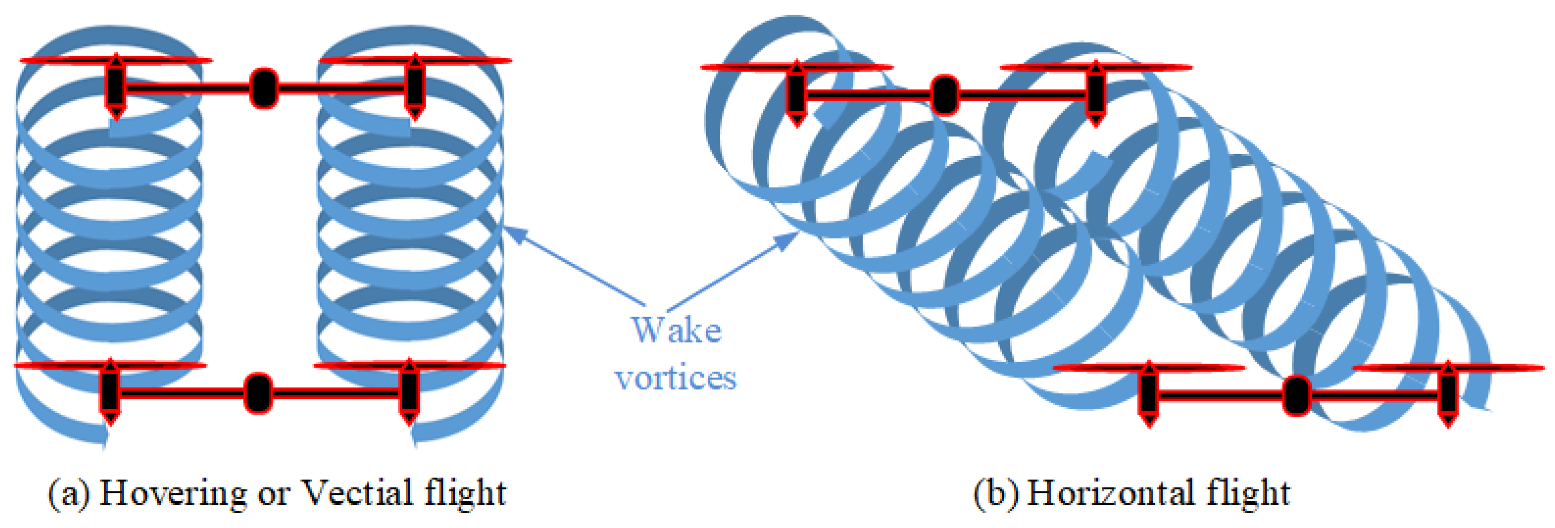
Figure 1. Wake interference during formation flying.
Aerospace 11 00865 g001
Figure 2. Low-speed reflow wind tunnel.
Aerospace 11 00865 g002
Figure 3. Experimental setup. (a) Test bench structure diagram; (b) schematic diagram of experimental measuring device.
Aerospace 11 00865 g003
Figure 4. (a) Rotor geometry; (b) rotor pitch angle and chord length distribution.
Aerospace 11 00865 g004
Figure 5. (a) Computational domain; (b) mesh of middle section.
Aerospace 11 00865 g005
Figure 6. Comparison of CFD and experimental data with literature [36] results.
Aerospace 11 00865 g006
Figure 7. (a) Thrust coefficient variation with rotor rotational speed at X = 0D; (b) thrust coefficient variation with rotor rotational speed at Z = 1D.
Aerospace 11 00865 g007
Figure 8. The bottom rotor thrust coefficient varies with different lateral and axial separations. (a) At 5000 RPM; (b) at 8000 RPM.
Aerospace 11 00865 g008
Figure 9. Velocity distribution of the mid-section of the two rotors at different separations. (a) At 5000 RPM; (b) at 8000 RPM.
Aerospace 11 00865 g009
Figure 10. Effect of vertical flight speed on isolated rotor thrust coefficient.
Aerospace 11 00865 g010
Figure 11. Thrust coefficient of bottom rotor with changes in lateral and axial separation. (a) At 0 m/s; (b) 2 m/s; (c) 5 m/s.
Aerospace 11 00865 g011
Figure 12. Bottom rotor’s C T / C T , s i n g l e with variation in vertical velocity. (a) Z = 1.0D; (b) 3.0D; (c) 7.5D; (d) 11.0D.
Aerospace 11 00865 g012
Figure 13. Velocity distribution of the mid-section of the two rotors at different separations during vertical flight. (a) At 5000 RPM, 2 m/s; (b) 8000 RPM, 2 m/s; (c) 5000 RPM, 5 m/s; (d) 8000 RPM, 5 m/s.
Aerospace 11 00865 g013
Figure 14. Effect of horizontal flight speed on isolated rotor thrust coefficient.
Aerospace 11 00865 g014
Figure 15. Thrust coefficient of bottom rotor with changes in lateral and axial separation. (a) At 2 m/s; (b) 5 m/s; (c) 10 m/s; (d) 15 m/s.
Aerospace 11 00865 g015
Figure 16. Lower rotor C T / C T , s i n g l e with variation in horizontal flight speed. (a) Z = 0.5D, (b) Z = 1.5D, (c) Z = 2.5D.
Aerospace 11 00865 g016
Figure 17. Velocity distribution of the mid-section of the two rotors at different separations when the horizontal flight speed is 2 m/s. (a) Z = 0.5D; (b) Z = 1.5D; (c) Z = 2.5D.
Aerospace 11 00865 g017
Figure 18. Velocity distribution of the mid-section of the two rotors at different separations when the horizontal flight speed is 10 m/s. (a) Z = 0.5D; (b) Z = 1.5D; (c) Z = 2.5D.
Aerospace 11 00865 g018
Table 1. Design of experiments.
Flight StateVariableValues
HoverRPM2000–8000
X/D0, 0.25, 0.5, 0.75, 1
Z/D1, 3, 5, 7.5, 11
VerticalRPM2000–8000
X/D0, 0.25, 0.5, 0.75, 1
Z/D1, 3, 5, 7.5, 11
Velocity2 m/s, 5 m/s
HorizontalRPM2000–8000
X/D1, 2, 3, 4, 6, 8, 10
Z/D0.5, 1.5, 2.5
Velocity2 m/s, 5 m/s, 10 m/s, 15 m/s
Disclaimer/Publisher’s Note: The statements, opinions and data contained in all publications are solely those of the individual author(s) and contributor(s) and not of MDPI and/or the editor(s). MDPI and/or the editor(s) disclaim responsibility for any injury to people or property resulting from any ideas, methods, instructions or products referred to in the content.