Abstract
Tilt-duct Unmanned Aerial Vehicles (UAV) combine the high-speed efficiency of fixed-wing aircrafts with vertical takeoff and landing (VTOL) and the hover capabilities of rotary-wing aircrafts while maximizing the advantages of ducted fans in terms of noise reduction, efficiency, and safety, making it a pivotal direction for the future of aviation such as urban air mobility. This paper concentrates on the design and optimization of the primary structures of a laboratory-designed reference tilt-duct UAV. Firstly, the general data of the reference tilt-duct UAV are presented. According to the load conditions, the overall structural layout design for the wing, fuselage, and empennage is carried out, where special attention has been paid to account for the requirements of VTOL/hover and cruise flight modes. Based on the structural layout, finite element models (FEM) are established and static analyses are performed. The results indicate that the design can fulfill the structural requirements during a flight mission. Furthermore, based on the Method of Feasible Directions (MFD) algorithm, we have carried out the optimization of the composite wing box that incorporates manufacturing constraints. Via optimization, the total mass of the wing box is reduced by 38.6%, i.e., from 3.73 kg to 2.29 kg. The results indicate that the combination of composite materials with a tilt-duct configuration holds significant potential for future high-efficiency and environmentally friendly aviation.
1. Introduction
Combining the high-speed feature of fixed-wing aircrafts with the vertical takeoff and hovering capabilities of rotorcrafts, tilting aircrafts hold immense promise for the future of versatile and adaptable aerial platforms. Among various tilting aircraft configurations, the tilt-duct aircraft is gaining increasing attention due to its advantages in efficiency, noise reduction, and safety, which has become a key direction in the development of the next generation of high-speed, efficient vertical takeoff and landing (VTOL) aircrafts [1]. Since the development and first flight of the Bell X-22 tilt-duct aircraft in the 1960s [2], extensive research has been undertaken in areas such as improving aerodynamic performance, structural efficiency, propulsion system effectiveness, and trajectory optimization in the pursuit of enhancing the range and payload capacity of tilt-duct aircrafts [3]. Recently, with the emergence of Urban Air Mobility (UAM) and advancements in technologies such as electric propulsion systems and composite materials, the tilt-duct configuration has regained attention as a highly promising design [4].
In the literature, a lot of research on tilt-duct VTOL aircraft and its related technologies has been carried out. Ref. [1] has presented the conceptual design of a tilt-duct VTOL UAV including descriptions of design requirements, mission profile, initial sizing, geometry selection, and basic overall aircraft design level performance. Ref. [5] has introduced the conceptual design of a UAM reference aircraft that has six tilting ducted proprotors, which indicates that the tilt-duct aircraft has advantages in performance such as lift-to-drag ratio and cruise airspeed when compared with other six-passenger NASA UAM reference aircraft configurations. Ref. [6] has performed a feasible study on the full electric tilt-duct VTOL aircraft based on a conceptual design and system level analysis, showing necessities for airframe and/or energy system improvement. Chang et al. [7] carried out full conversion flight tests for a 40 kg tilt-duct UAV for a better understanding of the transition features between the helicopter and the airplane mode. To overcome the scale-effect issue and to support the research community, scholars from Georgia Institute of Technology and NASA Langley Research Center have introduced a 453 kg (1000 lb) gross weight eVTOL reference aircraft with detailed aircraft geometry and comprehensive data from flight tests [8].
Another important research direction is the disciplinary study methodologies and tools related to tilt-duct eVTOL. Vegh et al. [9] compared SUAVE and NDARC (NASA Design and Analysis of Rotorcraft) regarding the competences for eVTOL aircraft weight, rotor models, hover-cruise conversion dynamics, wing aerodynamics, and battery discharge models. Ref. [10] has introduced an efficient eVTOL aerodynamic method that can model propeller–wing interactions and wing–wing interactions at the early design stage. Ref. [11] has widely reviewed ducted fan research activities with a focus on ducted fan aerodynamic simulations and experiments. Ref. [12] has built up weight calculation methods for eVTOL aircrafts based on existing aircrafts and Ref. [13] has constructed weight methods using a physics-based explicit approach in addition to surrogates. Refs. [14,15] have studied the propulsion system modelling approach for eVTOL aircrafts, especially on unconventional propulsion systems. Refs. [16,17] have investigated eVTOL trajectory optimization based on simplified performance models of aerodynamics, propulsion, and flight mechanics. As compared to other disciplinary methods, there is a relatively limited body of work in the field of structural design and optimization for tilt-duct eVTOL aircrafts. According to the knowledge of the authors, existing research related to tilt-duct eVTOLs mainly focuses on component-level structures such as the tilt-rotor wing [11,18,19,20,21,22,23,24] and rotor blade [25].
From the preceding literature review, it is evident that tilt-duct eVTOL, in comparison to other aircraft configurations, holds significant advantages and embraces promising applications in the future aviation landscape. Many existing studies have delved into various disciplines related to tilt-duct eVTOLs in depth. The next phase of eVTOL aircraft development spans from conceptual design to preliminary and detailed design. In this context, the work on the structural design and optimization for eVTOLs becomes crucial. We can find that there are few studies on the design and analysis of the complete structure of composite aircrafts, especially in the field of tilt-duct aircrafts. To fill the gap in this field to a certain extent, this study focuses on the design, analysis, and optimization of composite material structures for a laboratory-developed tilt-duct aircraft designed for experimental purposes. Different from the traditional fixed-wing aircraft or VTOL, the tilt-duct UAV needs to fulfill the flight mission in two flight modes, so the structural layout of the aircraft is redesigned in this paper, including the foldable wings and special fuselage structure. Subsequently, the stresses, strains, and deformations of the key components of this structural layout, such as the wing, fuselage, and empennage, are analyzed when they are subjected to different loads in different flight modes, so as to ensure that they can meet the safety and reliability requirements. Optimization of the structure is also a key part of the structural design process and we chose the most representative wing box structure as the object of optimization and used the optimization algorithm of the Method of Feasible Directions (MFD) algorithm. The optimization process aims to find the optimal composite thickness distribution (at minimum weight). As the goal of this paper is to carry out structure design, analysis, and optimization at the conceptual and preliminary aircraft design levels, which are often difficult to find in the existing literature, the results of the paper can provide baseline eVTOL aircraft-level structural data for the research community.
2. Materials and Methods
2.1. Reference Tilt-Duct UAV
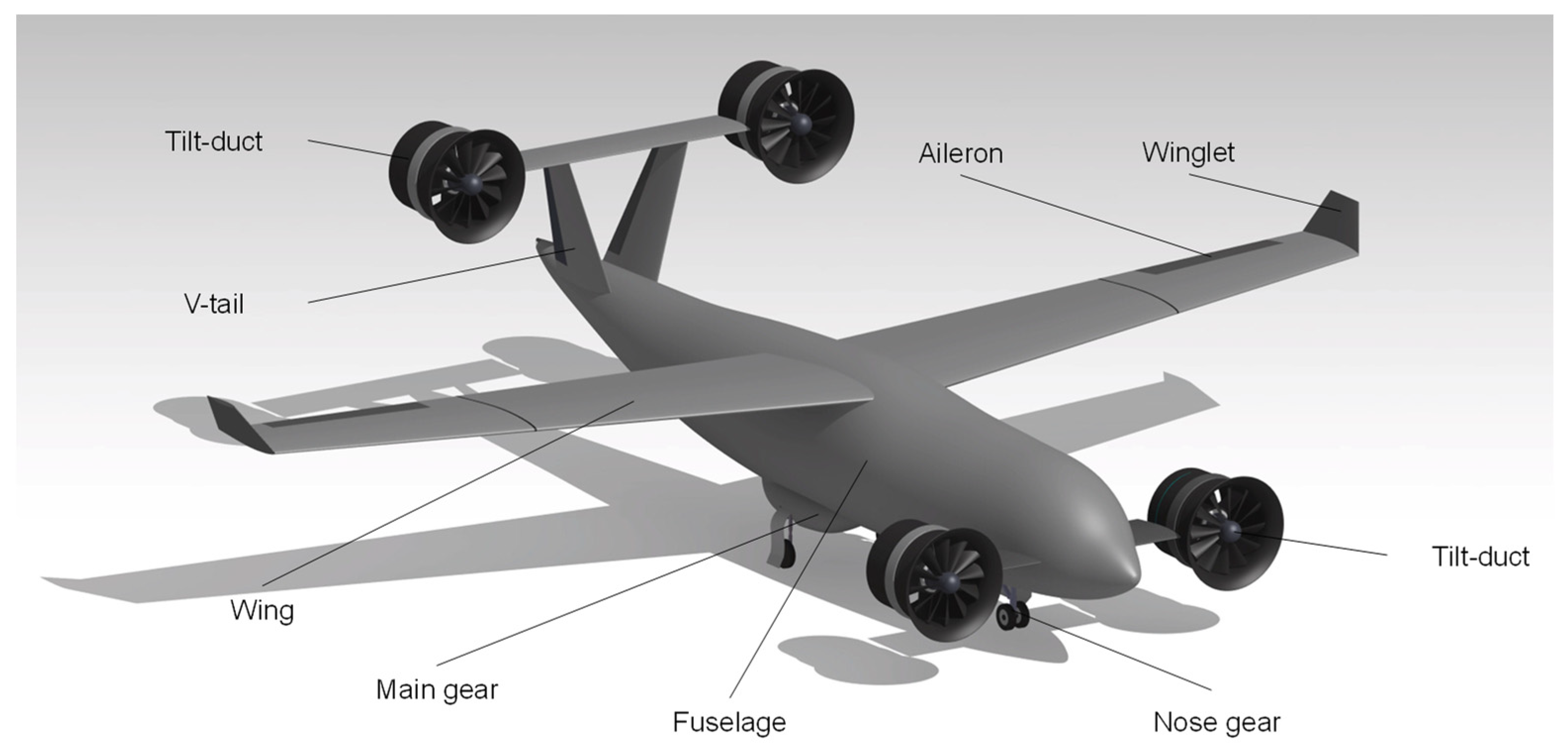
The reference tilt-duct UAV features a configuration with a fuselage, four tilt-duct fans, a V-tail, and foldable main wings equipped with winglets. Figure 1 provides the schematic view of the reference tilt-duct UAV and its main components.
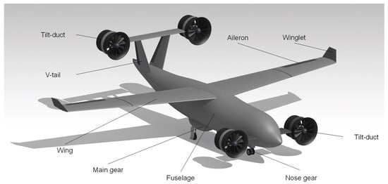
Figure 1.
3-D view of the reference tilt-duct UAV.
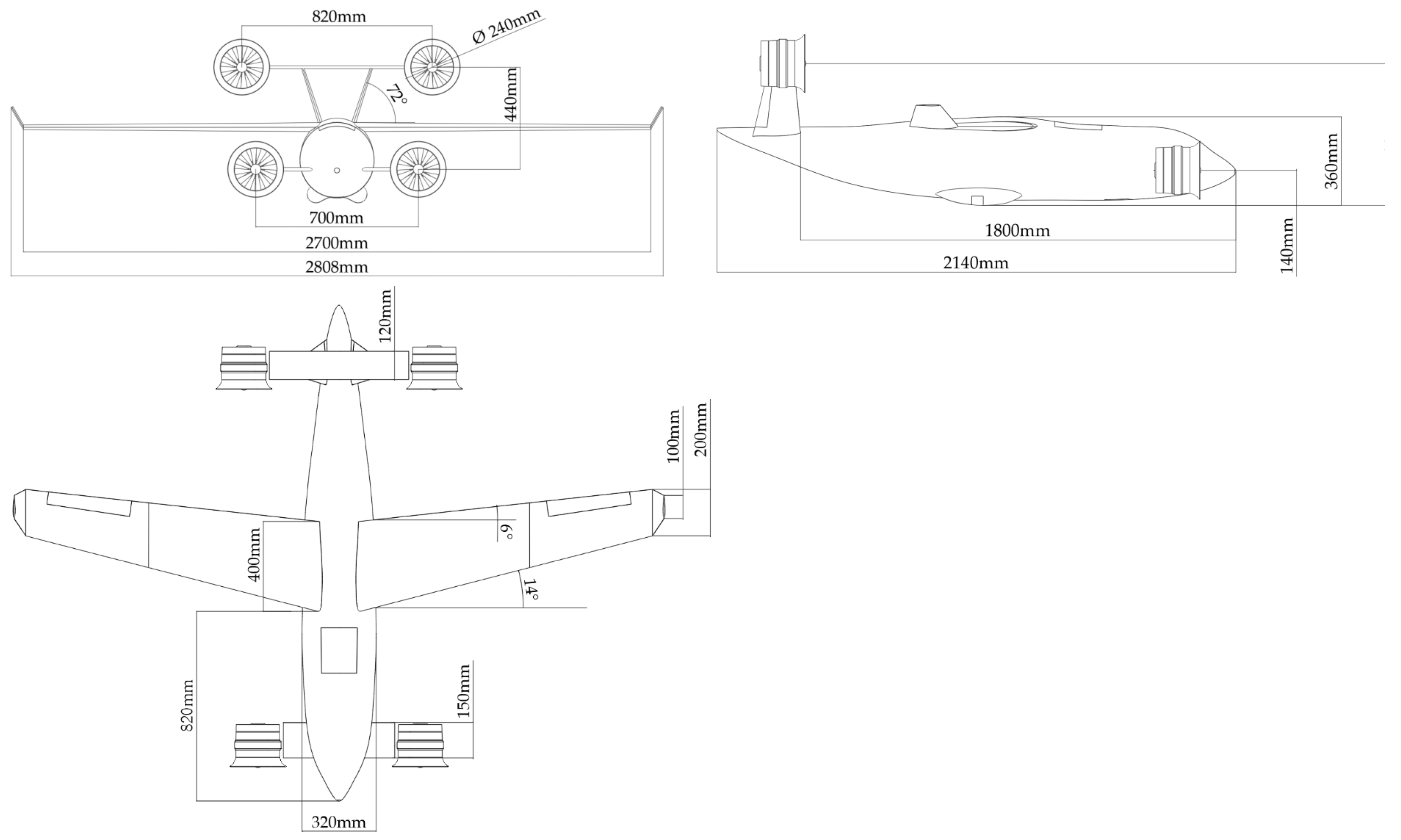
Figure 2 illustrates the front view, side view, and top view of the tilt-duct UAV, where the key dimensional parameters are also included in the figure.
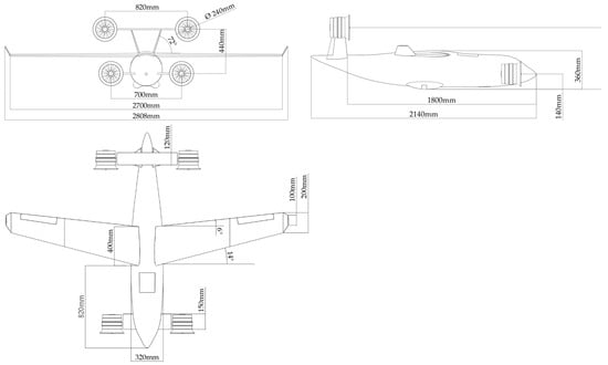
Figure 2.
Front view, side view, and top view of the reference tilt-duct UAV in cruise mode.
The hover mode and cruise mode of the reference tilt-duct UAV are illustrated in Figure 3. Note that in hover mode, the main wing can be folded to reduce the field requirements for takeoff and landing.
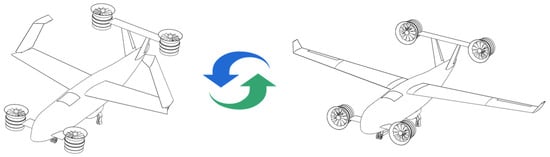
Figure 3.
Hover mode and cruise mode of the reference tilt-duct UAV, the arrow indicates that the UAV can switch between two flight modes.
The design mission profile of the reference tilt-duct UAV is presented in Figure 4, which includes vertical takeoff, transition, climb, cruise, descent, transition, and vertical landing.
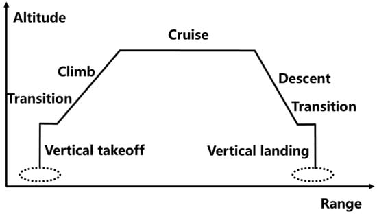
Figure 4.
Mission profile of the reference tilt-duct UAV.
2.2. Aircraft Structure Design
2.2.1. Wing Structure
The wing structure design for the tilt-duct UAV focuses on meeting specific requirements in cruise flight mode, where the wing acts as the primary lift-generating component. As mentioned previously, to accommodate the substantial wingspan and ensure stability during vertical takeoff and landing, a folding wing structure has been incorporated. This design enhances VTOL operational stability and minimizes required takeoff and landing space.
The main geometric parameters of the wing are listed as follows.
- Wing area 0.756 m2;
- Wing leading edge sweep angle 14°;
- Wing taper ratio 0.5;
- Wing aspect ratio 10.5.
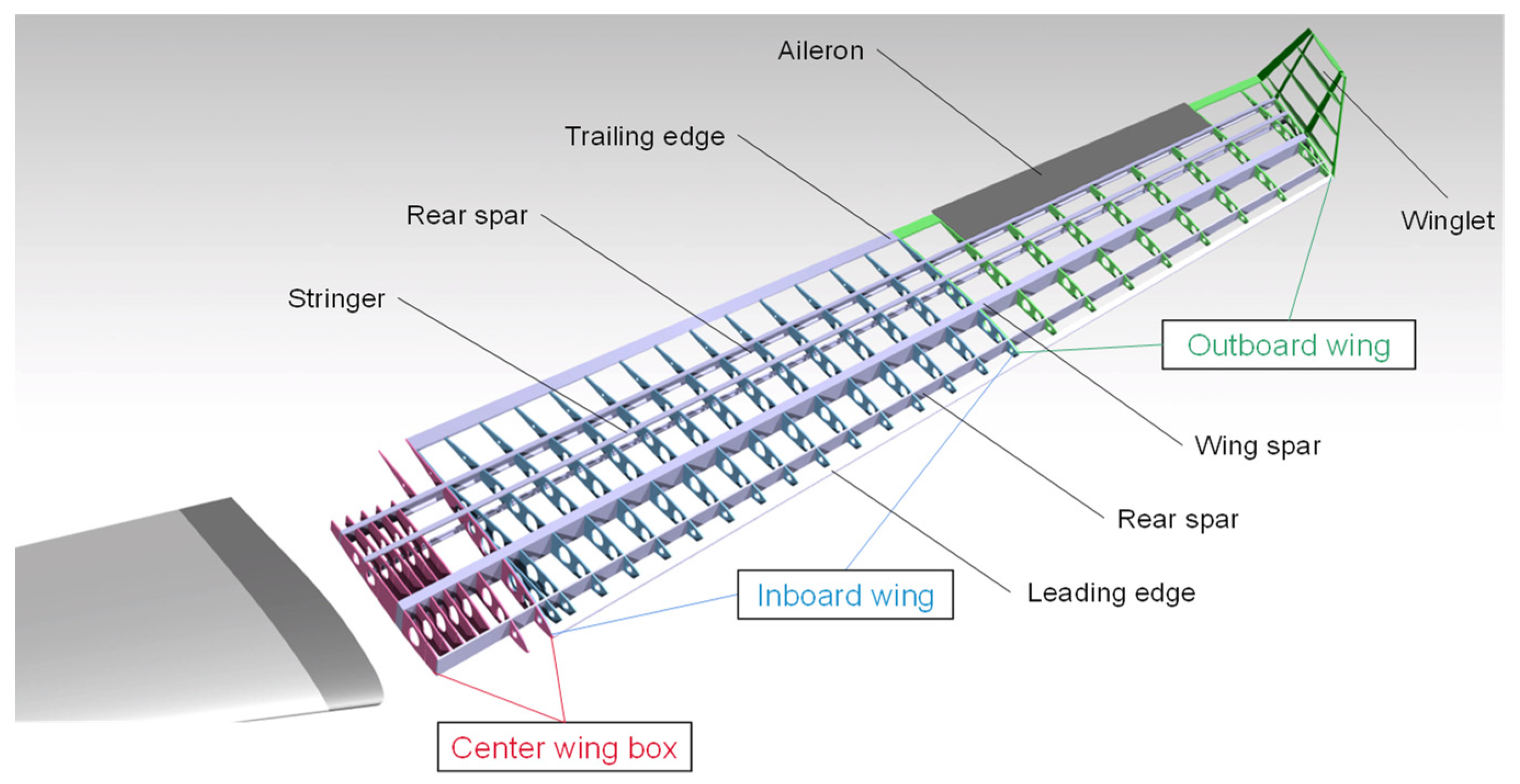
As the aircraft wing features a large wingspan, requiring the integration of aileron servos, folding mechanisms, and associated wiring within the wing structure, a thin-skinned single main spar structure is employed (cf. Figure 5), providing substantial torsional and bending stiffness. The wing structural design mainly focuses on the consideration of the cruise flight state. The wing spar connects to the central wing box through joints to transmit bending moments and shear forces to the fuselage. During cruise flight, the wing predominantly experiences aerodynamic loads distributed across the skin, which transfers these loads to the spars and wing ribs. The skin, being relatively thin, experiences stress distributed along its thickness. The specific structure of the wing is illustrated in Figure 5, with the wing spar positioned at 23% of the chord. The wing is divided into inner and outer sections, and the outer section can rotate upward around the hinge at the wingtip of the inner section, achieving a maximum angle of 120°. The load cases of the wing are mainly determined by the aerodynamic forces in cruise flight mode.
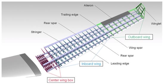
Figure 5.
Wing structure of the tilt-duct UAV.
2.2.2. Fuselage Structure
The design of the fuselage for the tilt-duct UAV requires careful consideration of aircraft load carrying requirements (to address the specific requirements to carry the equipment, loads, and batteries, and can accommodate retractable landing gear) and the integration of various components (seamless integration of different subsystems within the fuselage that are essential for optimal performance and functionality). The design strikes a balance between structural integrity, weight efficiency, and the efficient use of available space to meet both safety and operational requirements.
The main geometric parameters of the fuselage are listed as follows.
- Fuselage length 2.14 m;
- Fuselage width 0.318 m;
- Fuselage height 0.365 m.
Considering that the tilt ducts are installed at the nose and tail positions, this study adds four stiffening beams running through the fuselage (from nose to tail) based on the existing fuselage structure of fixed-wing aircraft, which can effectively transfer the forces generated by the ducts in hover mode. This design feature significantly enhances the fuselage’s bending capability and accessibility, subsequently increasing the available space for accommodating retractable landing gear, as well as facilitating the replacement of loads and equipment. Additionally, the stiffening beams are also connected to the center wing box to effectively transfer the lift generated by the wing in cruise mode Figure 6.
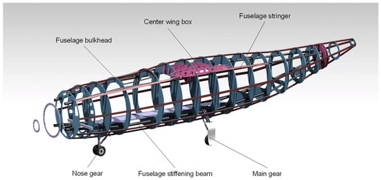
Figure 6.
Fuselage structure of the tilt-duct UAV.
2.2.3. Empennage Structure
The empennage structure design for the tilt-duct aircraft focuses on meeting specific requirements in both cruise mode and hover mode, where the empennage provides directional and longitudinal stability and maneuverability for the aircraft. In this study, particular attention has to be paid to the aerodynamic effects generated by the two ducted fans at the rear wing.
The main geometric parameters of the empennage are listed as follows.
- Tail area 0.046 m2;
- Tail leading edge sweep angle 5.7°;
- Tail taper ratio 0.5;
- Tail aspect ratio 2.2.
To mitigate the impact of the airflow generated by the ducted fans on the surfaces, we adopt a V-tail configuration. Additionally, the V-tail requires structural reinforcement to transmit the forces generated by the two ducted fans. Therefore, we utilize a two-spar, closely ribbed structure for the V-tail. Figure 7 illustrates the two-spar structural configuration of the empennage as well as the connection to the fuselage structure.
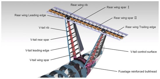
Figure 7.
Empennage structure of the tilt-duct UAV.
3. Results
The main components (i.e., spars, skins, bulkhead) are designed in carbon fiber-reinforced plastics, while ribs and connecting part are designed in aluminum alloy. The nonlinear finite element solver Optistruct was used for structural analysis.
3.1. Aircraft Structure Analysis Results
3.1.1. Wing Structure Analysis
For analysis, the structural components of the wing are simplified into wing spars, front and rear webs, skins, and ribs. Via establishing the finite element model (FEM) of the wing, a comprehensive structural analysis has been carried out. The wing is mainly subjected to aerodynamic loads during cruise mode, and we assume that if the lift across the wingspan is elliptical, it would be zero at the wingtips and maximum at the center. The load conditions of the wing include the wing aerodynamic loads, inertia loads, and maneuver loads in both the cruise and hover cases.
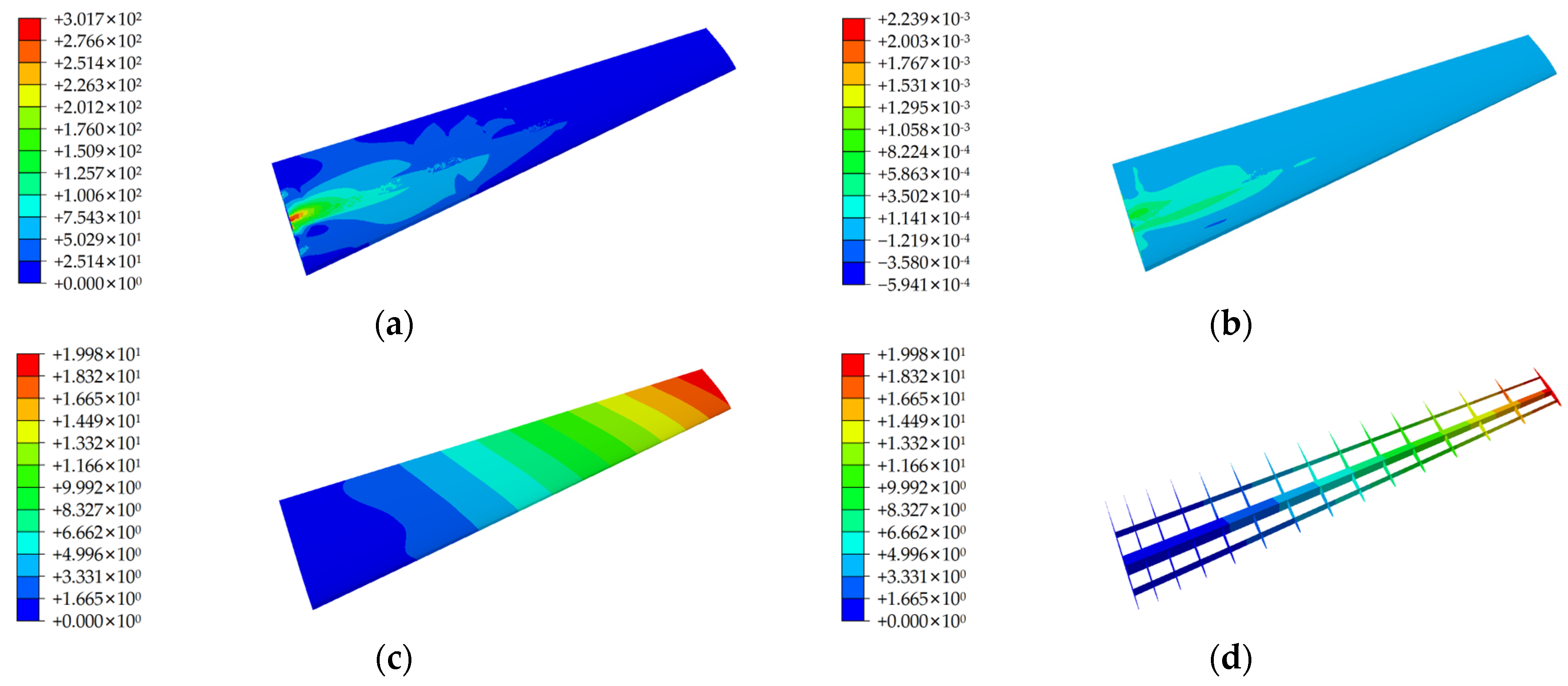
Figure 8 shows some representative wing structural analysis results based on FEM including wing strain distribution, wing stress distribution, and wing deformation. The maximum von Mises stress and the strain are identified at the joint between the wing spar and the central wing box. The majority of bending moments and shear forces are effectively transmitted through the joints of the front spar, resulting in raised stress–strain levels in the associated area.

Figure 8.
Wing structure analysis based on FEM. (a) Wing stress (Mpa). (b) Wing strain (με). (c) Wing deformation (mm). (d) Internal structure deformation (mm).
Furthermore, the maximum displacement is observed at the wing tip, with a ratio of 1.42% relative to the wingspan. This ratio, indicative of wing deformation, falls below the prescribed limit of 2.5%, signifying minimal wing deformation and affirming compliance with the required design requirements for stiffness.
3.1.2. Fuselage structure analysis
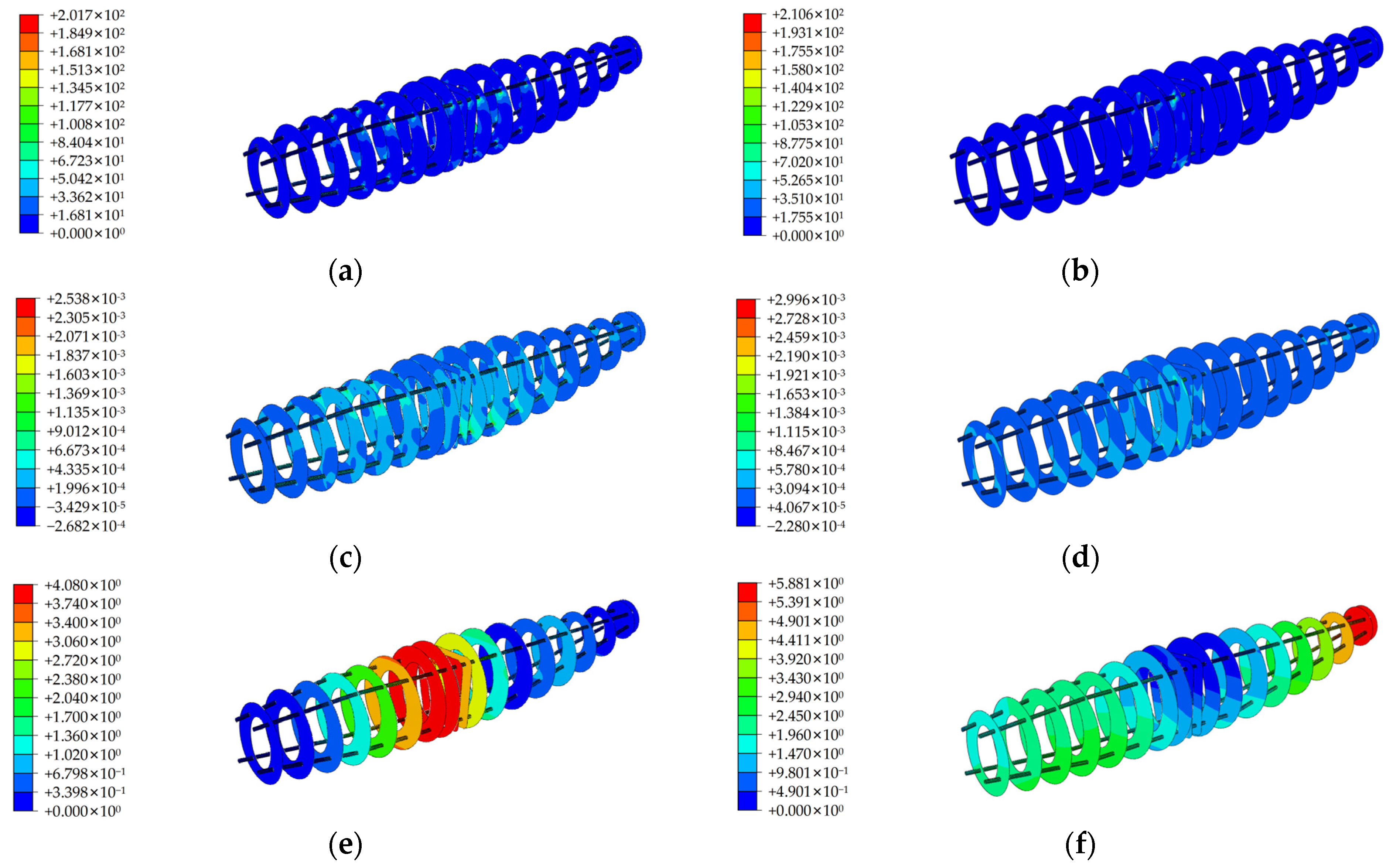
Following a similar procedure of wing structure analysis, the fuselage finite element model has been firstly established. The fuselage needs to fulfill the design requirements for both hover and cruise mode. Figure 9 presents the fuselage structure analysis results based on FEM including fuselage stress, strain, and deformation results in both hover and cruise modes.
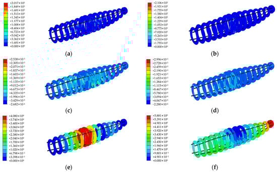
Figure 9.
Fuselage structure analysis based on FEM. (a) Fuselage stress at hover mode (Mpa). (b) Fuselage stress at cruise mode (Mpa). (c) Fuselage strain at hover mode (με). (d) Fuselage strain at cruise mode (με). (e) Fuselage deformation at hover mode (mm). (f) Fuselage deformation at cruise mode (mm).
3.1.3. Empennage Structure Analysis
Since the empennage is equipped with tilt-duct device at the wingtip, the structural analysis of the empennage must consider the two flight modes of hover and cruise. However, for simplicity, we do not consider the loading on the tail wing during the tilting process. Similar to the fuselage, the empennage must meet design requirements for both hover and cruise modes. The empennage structure is mainly exposed to upward forces generated by the duct in hover mode, and forward forces generated by the duct and aerodynamic forces in cruise mode.
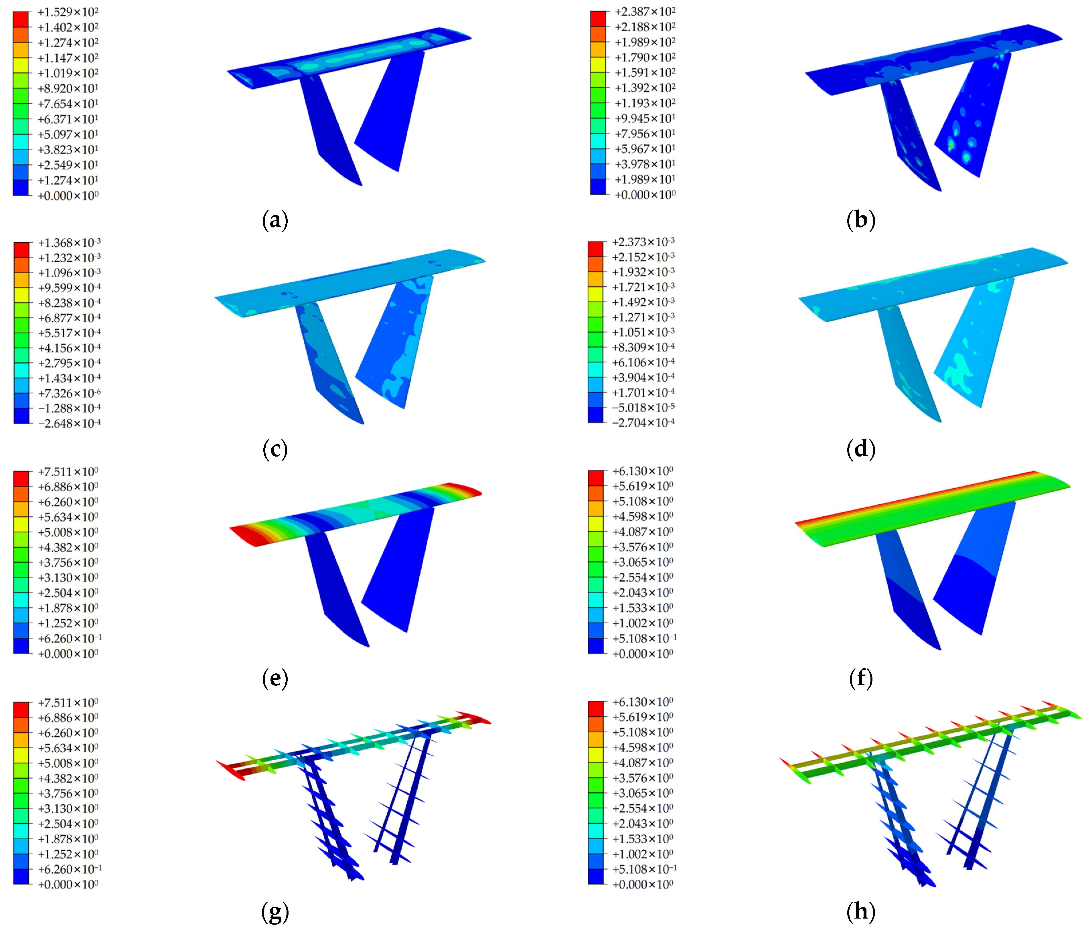
Figure 10 illustrates the tail structure analysis results based on FEM in hovering and cruise flight modes, respectively. The empennage structure results including skin strain, stress, and deformation fulfill the design requirements.
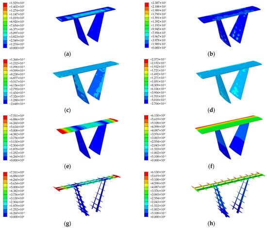
Figure 10.
Empennage structure analysis based on FEM. (a) Empennage stress at hover mode (Mpa). (b) Empennage stress at cruise mode (Mpa). (c) Empennage strain at hover mode (με). (d) Empennage strain at cruise mode (με). (e) Empennage deformation at hover mode (mm). (f) Empennage deformation at cruise mode (mm). (g) Empennage internal deformation at hover mode (mm). (h) Empennage internal deformation at cruise mode (mm).
In its hovering state, the maximum von Mises stress and the maximum strain concentrates at the connection between the wing spar and the V-tail spar. The maximum displacement is situated at the connection between the rear tilting ducted fans and the wing.
In its cruise flight state, the maximum von Mises stress and the maximum strain is located at the connection between the wing spar and the V-tail spar while the maximum displacement appears at the trailing edge of the rear wing.
3.2. Wing Structure Optimization Results
3.2.1. Finite Element Modelling
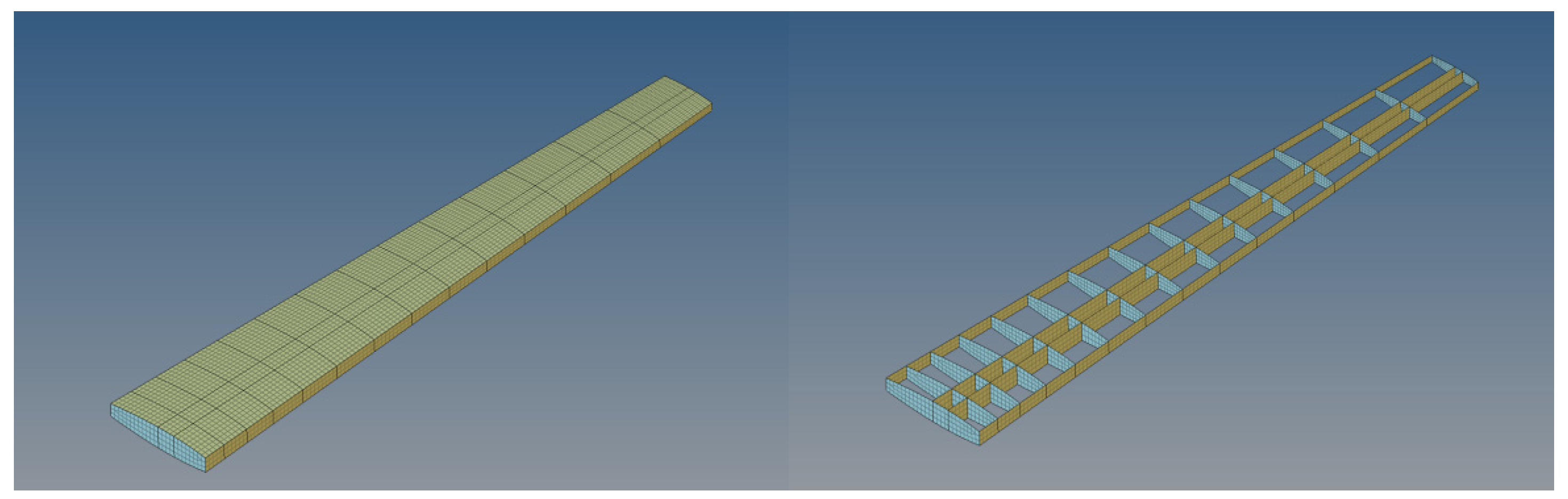
The wing box serves as the primary load-bearing structure of the wing, making its structural performance the central focus of analysis and optimization. On the basis of the previous section regarding wing structure design, we established a simplified wing box finite element model consisting of wing spars, wing ribs, and upper and lower skins for the wing’s structural optimization. Figure 11 shows the simplified finite element model of the wing structure. Note that composite materials are used for the skins, wing spars, and front and rear webs, and aluminum alloy is used for the wing ribs.
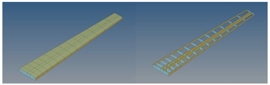
Figure 11.
Simplified finite element model of wing structure.
The loads involved in the optimization process are the same as mentioned in Section 3.1.1.
3.2.2. Composite Lay-Up Optimization
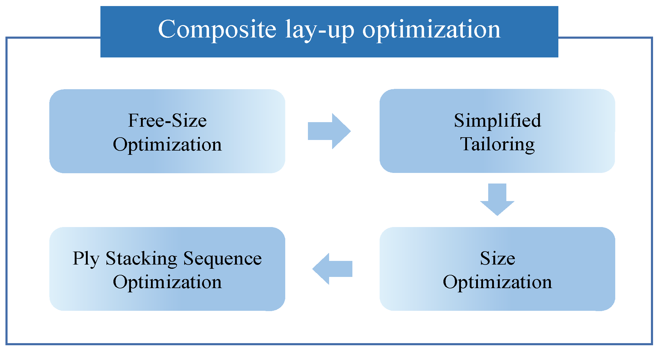
In this section we focus on the optimization of the composite wing box, as shown in Figure 12, including free-size optimization, lay-up shape tailoring, size optimization, and ply stacking sequence optimization. We formulate the wing box structure design as an optimization problem. The objective is to minimize the wing structure mass while satisfying the design constraints regarding strength, stiffness, and the requirements of the production process, including the minimum manufacturable ply thickness and the percentage of total ply thickness in a given direction. Figure 12 shows the overall optimization process of the composite wing box.
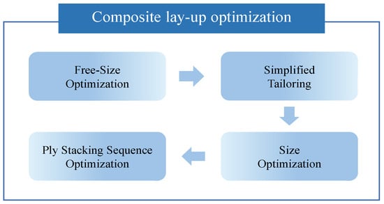
Figure 12.
Optimization process for the composite wing box.
To achieve the optimization goal, we employed the Method of Feasible Directions (MFD) algorithm. Its core principle is to transition from one feasible design to a better one, ensuring a decrease in the objective function while maintaining adherence to constraints. MFD is particularly effective for optimization challenges featuring numerous constraints and limited design variables, such as size and shape optimization.
- a.
- Free-size optimization and tailoring
The free-size optimization of the composite wing box aims to find the optimal thickness distribution that satisfies the constraints. The objective function is to minimize the mass of the wing box while satisfying the stress, strain, and manufacturing constraints. The manufacturing constraints include balanced lay-ups at an angle of ±45° for the outer ply, maximum thickness of the ply-ups, percentage of total lay-ups in a single direction, and thickness of the manufacturable single layer.
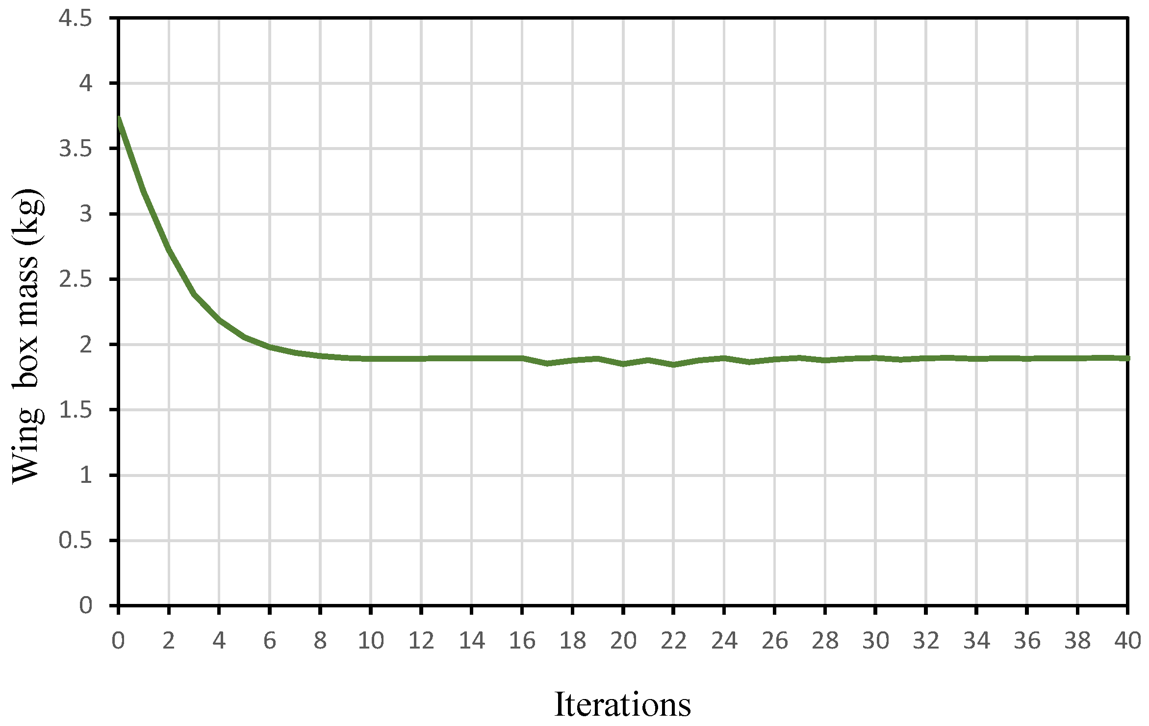
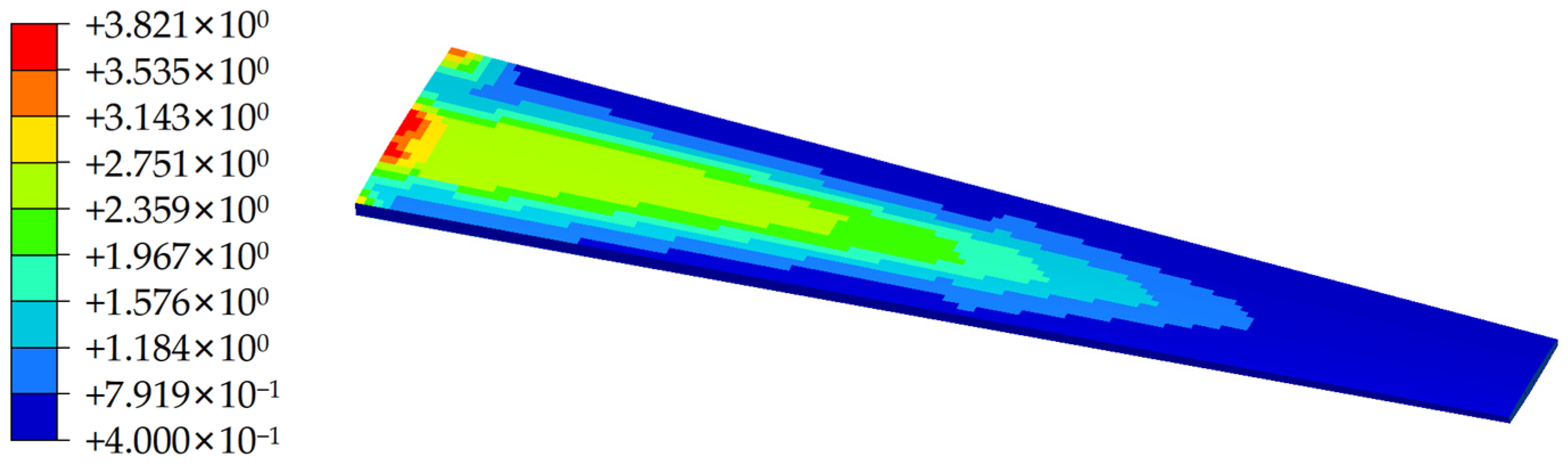
Figure 13 shows the history of the objective function with number of iterations. After 40 steps of iteration, the mass of the wing box is reduced from the initial 3.73 kg to 1.89 kg, i.e., a 49.3% reduction in which mass via free-size optimization, while the stress and strain design constraints are satisfied. The results of the overall thickness distribution of the composite wing box are shown in Figure 14.
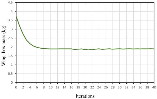
Figure 13.
History of the objective function with number of iterations.
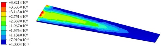
Figure 14.
Total thickness distribution of the composite wing box after free-size optimization.
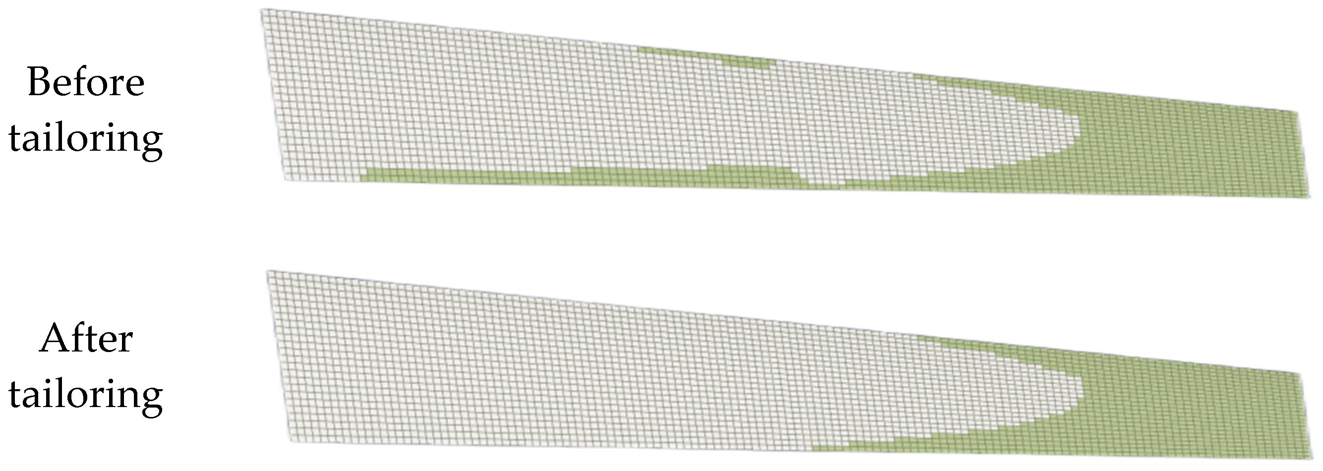
Since the shapes of the layers obtained from the free-size optimization are not regularly distributed, which creates a great difficulty in manufacturing, it is necessary to analyze and tailor each layer block to make it manufacturable and to prepare it for the next step in size optimization. It should be noted that the more conservative tailoring treatment was used, so it resulted in a slight increase in mass. Figure 15 shows the process of tailoring one of the layers of the skin.

Figure 15.
Schematic process of tailoring.
- b.
- Size optimization
The aforementioned free-size optimization produces layers of non-uniform thicknesses. Although technically feasible to produce, such configurations come with high costs. To fabricate more cost-effective components, the subsequent step involves size optimization.
The objective of size optimization is to determine the precise thickness of each layer for every angle and shape. This entails discretizing the non-uniform thickness of layers at each angle into uniform layers that satisfy manufacturing constraints
Seeking to minimize wing box mass as the same design objective, we add wingtip displacement constraints. Figure 16 shows the optimization history of the objective function with the number of iterations. As shown in the figure, after eight steps of iteration, the mass of the optimized wing box is converged to 2.29 kg, which indicates an increase of 8.1% relative to the mass of 2.10 kg after tailoring, which is due to the wingtip displacement constraints. The optimization history of the objective function (wing box mass) with the number of iterations is shown in Figure 16.
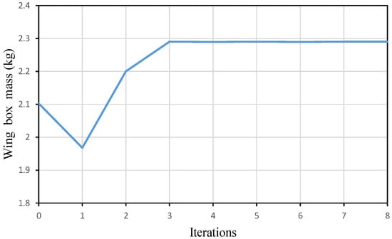
Figure 16.
Optimization history of the objective function with the number of iterations.
- c.
- Ply stacking sequence optimization
The overall mechanical performance of composite material structures varies with changes in the stacking sequence of plies. As such, it is necessary to optimize the stacking sequence to comply with the layering rules of composite materials, while also maintaining or improving their performance.
In the optimization of the stacking sequence, we keep the same design objective and design constraints as in size optimization. The design variables are chosen as a stacking sequence of plies for the wing spar and skin. The results from the ply stacking sequence optimization indicate that the wing box mass keeps the same as size optimization while the stress can be reduced from 415.1 MPa to 396.6 MPa.
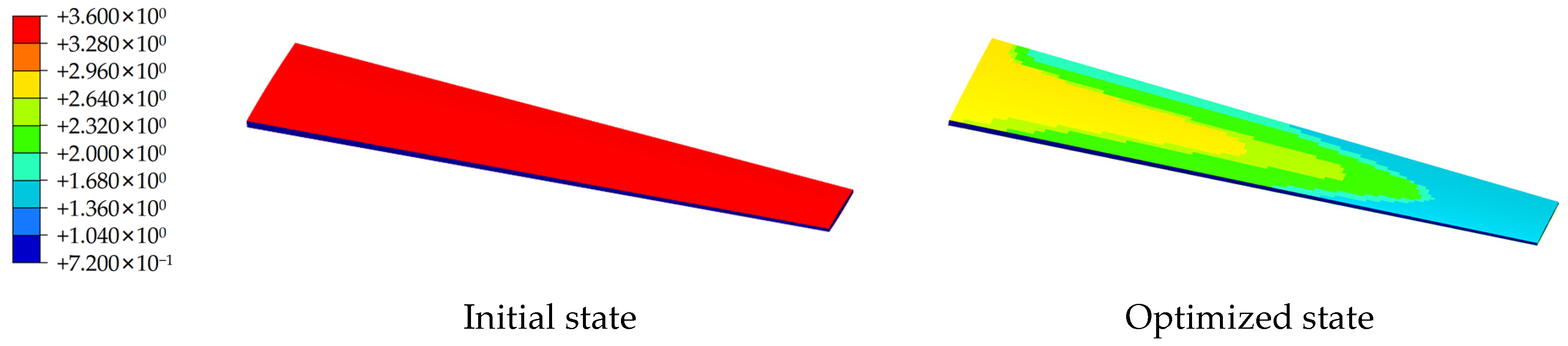
The result of the cascade order optimization is the final result of the wing box optimization. We compare the final optimized result with the initial design and show it in terms of thickness distribution. Referring to Figure 17, it can be observed that the initial state of the pavement is a complete equal thickness distribution, and the optimized pavement removes the less important cells and makes the thickness more rationally distributed.
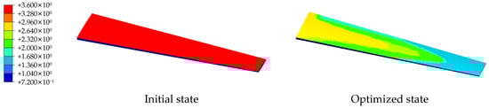
Figure 17.
Thickness distribution of the final optimized result compared to the initial design.
3.2.3. Discussion of Optimization Results
In summary, parameters such as the mass, displacement, stress, and strain of the composite wing box at each stage of the optimization process are shown in Table 1.

Table 1.
Changes in each performance parameter of the wing box structure during the combination optimization process.
As can be seen in the tables, the composite wing box of the tilt-duct UAV initial total mass of the wing box has been reduced from 3.73 kg to 2.29 kg, which is a 38.6% mass reduction. While maintaining the original level of load-bearing capacity, the displacement, strain, and stress of the wing box structure have all increased compared to the values prior to optimization. This indicates that, in order to achieve weight reduction, there has been a trade-off in terms of some aspects of strength, stiffness, and stability performance. However, the displacement, strain, and stress all still meet the design constraints.
In comparison to the initial design, the wing box structure, following the optimization approach, better utilizes the material’s load-bearing capacity while meeting the design constraints, which significantly enhances the structural efficiency, showcasing the design flexibility of composite materials. This lays a solid foundation for the subsequent manufacturing of the actual tilt-duct UAV.
4. Conclusions
Tilt-duct UAV takes advantages of a ducted fan for efficiency, noise reduction, and safety as compared to isolated rotors, as well as amalgamating the high-speed efficiency of fixed-wing aircrafts with the versatile capabilities of VTOL and the hovering capabilities of rotary-wing aircrafts, standing out as a crucial trajectory for the future of aviation, especially in the context of urban air mobility. In this paper we have carried out the design and optimization for the primary structures of a laboratory-designed reference tilt-duct UAV, where the data can serve as a good reference for the research community. The main conclusions are summarized as follows.
- The primary structure for the wing, fuselage, and empennage has been designed for a laboratory-developed reference tilt-duct UAV with general data for the aircraft included.
- Derived from the structural layout design for the wing, fuselage, and empennage, static analyses based on FEM have been carried out. The structural analysis results indicate that the design can fulfill structural requirements in cruise and hover/VTOL flight conditions, but more detailed studies on tilting process are still needed in the future.
- The optimization study, accounting for manufacturing constraints of the composite wing box, resulted in a substantial 38.6% reduction in the total mass of the wing box, exemplifying the promising potential for weight efficiency improvements within the tilt-duct configuration.
Author Contributions
Conceptualization, S.X. and Y.L.; Data curation, S.X.; Formal analysis, S.X. and Y.L.; Funding acquisition, Y.L.; Investigation, S.X. and Y.L.; Methodology, S.X. and Y.L.; Project administration, Y.L., J.Z. and Y.Z.; Resources, Y.L., J.Z. and Y.Z.; Software, S.X.; Supervision, Y.L.; Validation, S.X. and Y.L.; Visualization, S.X.; Writing—original draft, S.X. and Y.L.; Writing—review & editing, Y.L., J.Z. and Y.Z. All authors have read and agreed to the published version of the manuscript.
Funding
This research was funded by Chinese Ministry of Science and Technology, grant number 2023YFB3002800.
Data Availability Statement
The data presented in this study are available on request from the authors.
Conflicts of Interest
The authors declare no conflicts of interest.
References
- Armutcuoglu, O.; Kavsaoglu, M.S.; Tekinalp, O. Tilt duct vertical takeoff and landing uninhabited aerial vehicle concept design study. J. Aircr. 2004, 41, 215–223. [Google Scholar] [CrossRef]
- Paxhia, V.B.; Sing, E.Y. X-22a design development. J. Aircr. 1965, 2, 2–8. [Google Scholar] [CrossRef]
- Zhang, T.; Barakos, G.N. Review on ducted fans for compound rotorcraft. Aeronaut. J. 2020, 124, 941–974. [Google Scholar] [CrossRef]
- Kiesewetter, L.; Shakib, K.H.; Singh, P.; Rahman, M.; Khandelwal, B.; Kumar, S.; Shah, K.A. Holistic review of the current state of research on aircraft design concepts and consideration for advanced air mobility applications. Prog. Aerosp. Sci. 2023, 142, 100949. [Google Scholar] [CrossRef]
- Whiteside, S.K.; Pollard, B.P. Conceptual design of a tiltduct reference vehicle for urban air mobility. In Proceedings of the Aeromechanics for Advanced Vertical Flight Technical Meeting, Transformative Vertical Flight 2022, San Jose, CA, USA, 25–27 January 2022. [Google Scholar]
- Zhang, J.; Liu, Y.; Jiang, T.; Zheng, Y. Conceptual Design and System Level Analysis of Tilt-Duct eVTOL Aircraft. In Proceedings of the Asia-Pacific International Symposium on Aerospace Technology, Jeju, Republic of Korea, 15–17 November 2021. [Google Scholar]
- Chang, S.; Cho, A.; Choi, S.; Kang, Y.; Kim, Y.; Kim, M. Flight testing full conversion of a 40-kg-class tilt-duct unmanned aerial vehicle. Aerosp. Sci. Technol. 2021, 112, 106611. [Google Scholar] [CrossRef]
- German, B.; Jha, A.; Welstead, J.; Whiteside, S.; Blaesser, N.J. Design and Programmatic Overview of the Research Aircraft for eVTOL Enabling techNologies (RAVEN) Activity. In AIAA AVIATION 2023 Forum; AAIA: Fairfax, VA, USA, 2023. [Google Scholar]
- Vegh, J.M.; Botero, E.; Clark, M.; Smart, J.; Alonso, J.J. Current capabilities and challenges of NDARC and SUAVE for eVTOL aircraft design and analysis. In Proceedings of the 2019 AIAA/IEEE Electric Aircraft Technologies Symposium (EATS), Indianapolis, IN, USA, 22–24 August 2019. [Google Scholar]
- López, N.S.; Santamaría, A.M.; Castro, S.G. Preliminary aerodynamic design and load calculation of a long-range eVTOL aircraft. In AIAA SCITECH 2022 Forum; AAIA: Fairfax, VA, USA, 2022. [Google Scholar]
- Wadia, K.; Buszek, M.; Poliakov, N.; Castro, S.G. Preliminary design and analysis of crashworthy structures for a long-range eVTOL aircraft. In AIAA Scitech 2022 Forum; AAIA: Fairfax, VA, USA, 2022. [Google Scholar]
- Shim, S.; Ahn, C.; Chang, Y.; Cha, W.; Hwang, M.; Park, S.; Shin, S.J. Weight Fraction Estimation for EVTOL Vehicle Sizing. In AIAA AVIATION 2023 Forum; AAIA: Fairfax, VA, USA, 2023. [Google Scholar]
- Smart, J.T.; Alonso, J.J. Primary Weight Estimation for eVTOLs via Explicit Analysis and Surrogate Regression. In AIAA Aviation 2019 Forum; AAIA: Fairfax, VA, USA, 2019. [Google Scholar]
- Critchfield, T.; Ning, A. Low-fidelity design optimization and parameter sensitivity analysis of tilt-rotor eVTOL electric propulsion systems. In AIAA SCITECH 2023 Forum; AAIA: Fairfax, VA, USA, 2023. [Google Scholar]
- Thu, Z.W.; Ahn, J.H.; Lee, J.L.; Kwon, D.Y.; Choi, Y.J.; Won, W.J.; Tyan, M.; Lee, J.W. Enhanced Performance Prediction of Hydrogen Fuel Cell Powered eVTOL UAV. In AIAA AVIATION 2022 Forum; AAIA: Fairfax, VA, USA, 2022. [Google Scholar]
- Wu, Y.; Deniz, S.; Shi, Y.; Wang, Z.; Huang, D. Precision Landing Trajectory Optimization for eVTOL Vehicles with High-Fidelity Aerodynamic Models. In AIAA AVIATION 2023 Forum; AAIA: Fairfax, VA, USA, 2023. [Google Scholar]
- Chauhan, S.S.; Martins, J.R. Tilt-wing eVTOL takeoff trajectory optimization. J. Aircr. 2020, 57, 93–112. [Google Scholar] [CrossRef]
- Belardo, M.; Beretta, J.; Marano, A.D.; Diodati, G.; Paletta, N.; Di Palma, L. On the preliminary structural design strategy of the wing of the Next-Generation Civil Tiltrotor technology demonstrator. Int. J. Aeronaut. Space Sci. 2021, 22, 613–624. [Google Scholar] [CrossRef]
- Belardo, M.; Marano, A.D.; Beretta, J.; Diodati, G.; Graziano, M.; Capasso, M.; Ariola, P.; Orlando, S.; Di Caprio, F.; Paletta, N.; et al. Wing structure of the Next-Generation Civil Tiltrotor: From concept to preliminary design. Aerospace 2021, 8, 102. [Google Scholar] [CrossRef]
- Kambampati, S.; Smith, E.C. Aeroelastic optimization of high-speed tiltrotor wings with wing extensions and winglets. J. Aircr. 2017, 54, 1718–1727. [Google Scholar] [CrossRef]
- Kim, T.; Lim, J.; Shin, S.; Kim, D.H. Structural design optimization of a tiltrotor aircraft composite wing to enhance whirl flutter stability. Compos. Struct. 2013, 95, 283–294. [Google Scholar] [CrossRef]
- Marano, A.D.; Belardo, M.; Beretta, J.; Starace, F.; Orlando, S.; Punzi, C.; Frajese, R.; Paletta, N.; Di Palma, L. Aeroelastic Tailoring of the Next Generation Civil Tiltrotor Technological Demonstrator Composite Wing. Aerospace 2022, 9, 335. [Google Scholar] [CrossRef]
- Marano, A.D.; Diodati, G.; Paletta, N.; Di Palma, L.; Belardo, M.; Nour, P.A. Structural Scalability Preliminary Studies for the Next Generation Civil Tiltrotor Composite Wing. Aerospace 2023, 10, 478. [Google Scholar] [CrossRef]
- Park, J.S.; Jung, S.N.; Lee, M.K.; Kim, J.M. Design optimization framework for tiltrotor composite wings considering whirl flutter stability. Compos. Part B Eng. 2010, 41, 257–267. [Google Scholar] [CrossRef]
- Sun, F.; Jiang, C.; Shen, Y.; Wang, H. Surrogate Model-Based Parametric Structural Design of a Composite Tiltrotor Blade. In Proceedings of the Asia-Pacific International Symposium on Aerospace Technology, Jeju, Republic of Korea, 15–17 November 2021. [Google Scholar]


Disclaimer/Publisher’s Note: The statements, opinions and data contained in all publications are solely those of the individual author(s) and contributor(s) and not of MDPI and/or the editor(s). MDPI and/or the editor(s) disclaim responsibility for any injury to people or property resulting from any ideas, methods, instructions or products referred to in the content. |
© 2024 by the authors. Licensee MDPI, Basel, Switzerland. This article is an open access article distributed under the terms and conditions of the Creative Commons Attribution (CC BY) license (https://creativecommons.org/licenses/by/4.0/).