Article

The Angular Momentum Unloading of the Asymmetric GEO Satellite by Using Electric Propulsion with a Mechanical Arm

1
College of Astronautics, Nanjing University of Aeronautics and Astronautics, Nanjing 210016, China
2
Shanghai Aerospace Control Technology Institute, Shanghai 201109, China
3
Shanghai Key Laboratory of Aerospace Intelligent Control Technology, Shanghai 201109, China
4
Shanghai Academy of Spaceflight Technology, Shanghai 201109, China
*
Authors to whom correspondence should be addressed.
Aerospace 2024, 11(4), 290; https://doi.org/10.3390/aerospace11040290
Submission received: 3 March 2024 / Revised: 29 March 2024 / Accepted: 3 April 2024 / Published: 9 April 2024
(This article belongs to the Section Aeronautics)

Abstract

:
A high-precision attitude control satellite uses an angular momentum exchange device such as a flywheel or a control moment gyro as the actuator for attitude stability control. Once the accumulation of angular momentum exceeds the upper limit of the angular momentum exchange device, the satellite will lose its attitude control ability. Therefore, it is necessary to unload the angular momentum exchange device to ensure the attitude control ability of the satellite platform. The angular momentum accumulation of GEO(Geosynchronous Orbit, GEO) satellites with asymmetric structure can reach 40 Nms per day, and the accumulation speed is more than 20 times that of GEO satellites with symmetrical structure. Therefore, it is necessary to carry out angular momentum unloading for GEO satellites with asymmetric structure every day. The previous method of angular momentum unloading using electric propulsion has weak unloading capacity, which is not suitable for angular momentum unloading of asymmetric satellites. This paper presents a method of angular momentum unloading using a four-joint mechanical arm plus an electric thruster. Large angular momentum unloading with near-zero burn-up can be achieved through the thrust generated by station keeping. In addition, the problem of attitude and orbit coupling control can be solved by controlling the thrust direction of the electric thruster with a mechanical arm.

1. Introduction

A high-precision attitude control satellite uses an angular momentum exchange device such as a flywheel or a control moment gyro as the actuator for attitude stability control. Once the angular momentum accumulation of the satellite exceeds the upper limit of the capability of the angular momentum exchange device, the satellite will lose its attitude control ability, so the angular momentum exchange device needs to be unloaded to ensure the attitude control ability of the satellite platform. Asymmetrical GEO satellites are generally equipped with single-wing sails or carry large asymmetric loads. The angular momentum accumulated on a surface of such a satellite can reach 40 Nms per day, which is more than 20 times faster than that of a symmetrical GEO satellite. Therefore, it is necessary to provide a large unloading force every day to achieve the unloading of the angular momentum of such a satellite.
At present, chemical propulsion is commonly used in engineering to unload angular momentum. However, the specific impulse of chemical propellants is low, and more propellants are consumed to unload the corresponding angular momentum. The specific impulse of EP (Electric Propulsion, EP) is 5~10 times that of chemical propulsion, and the propellant consumption of the same speed increment is only about 10~20% of chemical propulsion. Therefore, the use of EP can increase the life of satellites and help meet the needs of long life of high-orbit satellite platforms. In addition, the EP is smaller than the chemical propulsion. The use of EP for orbit and attitude control and angular momentum unloading has less disturbance torque to the satellite, which is helpful to realize the high-precision attitude and orbit control of the satellite. Therefore, GEO satellites with all-EP have become a trend.
In recent years, many scholars have studied the use of EP for angular momentum unloading. Walsh [1] introduced the GEO satellite unloading scheme using four-vector EP of a Boeing 702SP satellite. The angular momentum unloading of GEO satellites is realized by slightly deflecting the EP vector to form the unloading torque. By iterating the deflection angle of the EP vector several times, the unloading accuracy of angular momentum is further improved. Ma [2] et al. adopted the scheme of four-vector EP of a Boeing 702SP platform. The angular deflection algorithm of the EP for angular momentum unloading in this scheme is optimized. Although the accuracy of angular momentum unloading is slightly decreased, the calculation amount of angular momentum unloading is significantly reduced, which is conducive to the realization of autonomous angular momentum unloading on board. However, the four-vector EP scheme is not suitable for large angular momentum unloading. Weiss [3,4] introduced the angular momentum unloading scheme of GEO satellites using six-fixed EP, which has a large angular momentum unloading capacity. Li et al. [5] adopted the scheme of a double four-degrees-of-freedom robotic arm plus an EP. The possibility of angular momentum unloading by using the propulsion generated by station keeping (SK) of GEO satellites is discussed.
The above scheme of angular momentum unloading by EP mainly has the following problems [6,7,8,9,10,11,12,13,14,15]:
(1)
The angular momentum unloading scheme of four-vector EP has the characteristics of small deflection angle of electric thrust, weak position and attitude adjustment ability, small angular momentum unloading ability, etc., which cannot meet the requirements of angular momentum unloading of asymmetric structure satellites;
(2)
Although the angular momentum unloading scheme with fixed EP can achieve large angular momentum unloading, the thrust of angular momentum unloading cannot be fully used for SK of GEO satellites, resulting in fuel waste. The fixed installation of electric thrusters cannot realize the active adjustment of position and attitude, and the number of electric thrusters to be configured is large, which is difficult to be deployed on GEO satellites.
In the literature [16,17,18], we have studied the NSSK (north–south station keeping, NSSK) and EWSK (east–west station keeping, EWSK) of GEO satellites by using a mechanical arm and EP. This paper uses the mechanical arm to adjust the position and attitude of thrust generated during SK, and the three-axis large angular momentum unloading of asymmetrical satellite is realized. The angular momentum unloading algorithm studied in this paper has the following three innovations:
(1)
In the past, 2- to 4-vector electric thrusters were needed to achieve small angular momentum unloading. In this paper, only one EP with a mechanical arm is needed to achieve large angular momentum unloading, which can reduce the hardware configuration on board;
(2)
In the past, angular momentum unloading required ignition in 2 to 4 different orbital arcs. In this paper, the angular momentum unloading can be achieved only by firing in one orbit arc, which reduces the number of ignition times.
(3)
In the process of attitude maneuvering, SK and angular momentum unloading can be carried out at the same time, which can realize complex attitude and orbit coupling control.

2. Materials and Methods

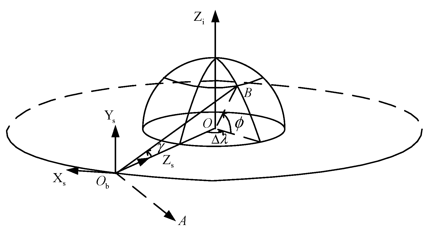
2.1. Establishment of Coordinate System

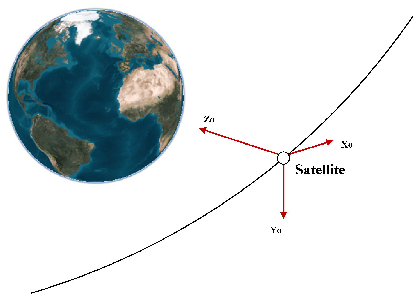
2.1.1. Satellite Orbital Coordinate System

The orbital coordinate system O o X o Y o Z o of the satellite is shown in Figure 1, and its definition is as follows: the origin Oo is located at the center of mass of the satellite; the OoZo axis points to the center of the earth; OoYo points to the negative normal of the orbital plane of the satellite; the OoXo, OoYo axis and OoZo axis form the right-hand orthogonal coordinate system.

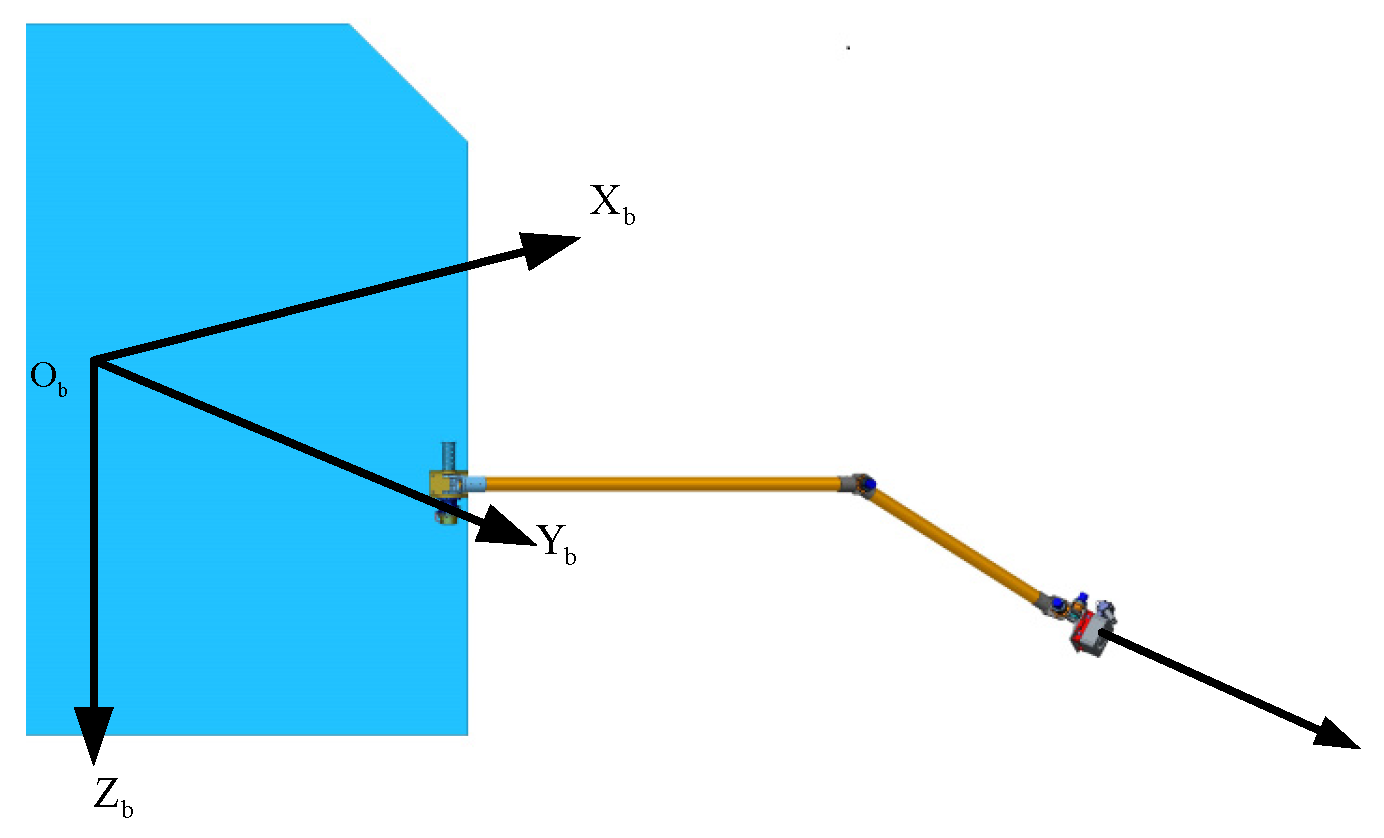
2.1.2. Satellite Body Coordinate System

The body coordinate system of the satellite is represented as O b X b Y b Z b , and the coordinate origin O b is located at the center of mass of the satellite. When the three-axis attitude of the satellite is zero, the body coordinate system of the satellite coincides with the orbital coordinate system of the satellite.

2.1.3. Nominal Coordinate System

The layout scheme of EP with a mechanical arm adopted in this paper is shown in Figure 2. After the mechanical arm is deployed, the mechanical arm and the solar wing are located in the south and north directions of the GEO satellite, respectively. For the convenience of discussion, it is assumed that during the stable operation of the satellite in orbit, the electric thrust points to the Y b direction of the satellite.
This kind of EP with a mechanical arm can point to the positive or negative normal direction of the orbital coordinate system, which can achieve efficient NSSK [6]. The thrust vector is slightly deflected to generate tangential thrust during NSSK, and the mean longitude keeping can be achieved at the same time [7]. The thrust vector is slightly deflected to generate radial thrust during NSSK, and the eccentricity keeping can be achieved at the same time [8]. On the basis of the SK function, the position of the end of the mechanical arm is properly deflected, and a wide range of angular momentum unloading can be realized. The motion range of the mechanical arm is small, and the electric thrust only needs to be turned on once per orbit.
If there is only propulsion to the south or north, the incremental speed used for mean longitude keeping will cause the eccentricity vector to diverge in one direction [6,7]. Therefore, the direction of propulsion needs to be alternating north–south during NSSK to prevent the eccentricity vector from diverging in one direction. Definition S ψ represents the flight state of the satellite. When the satellite is flying forward (the yaw attitude of the satellite ψ = 0 ° ), S ψ > 0 , the EP is located on the south side of the satellite, producing a speed increment from south to north, providing the positive normal speed increment of the orbital plane. When the satellite is flying backward (satellite yaw attitude ψ = 180 ° ), S ψ < 0 , the electric push is located on the north side of the satellite, producing a speed increment from north to south, providing a negative normal speed increment of the orbital plane.
Due to the limited range of activity of the mechanical arm, it is necessary to change the direction of the mechanical arm with the electric thruster to the south or north by switching the forward flight and backward flight state of the satellite, so as to change the direction of thrust. Therefore, the concept of “nominal coordinate system” is introduced in order to describe the rotation process of the manipulator and the control process of attitude disrotation.
When the satellite is flying forward, the nominal coordinate system coincides with the orbital coordinate system of the satellite. When a satellite is flying backward, the nominal coordinate system is obtained by rotating the orbital coordinate system 180° around its yaw axis. Thus, the quaternion from the J2000 coordinate system to the nominal coordinate system is:
q is = q io q os
where q os is the attitude quaternion from orbital coordinate system to nominal coordinate system, and its expression is as follows:
q os = { [ 1 0 0 0 ] S ψ > 0 [ 0 0 0 1 ] S ψ < 0
In Formula (1), q io is the attitude quaternion from the J2000 coordinate system to the orbital coordinate system, and its expression is as follows:
q io = [ cos Ω + u 2 cos i 2 cos Ω u 2 sin i 2 sin Ω u 2 sin i 2 sin Ω + u 2 cos i 2 ] [ 0.5 0.5 0.5 0.5 ] [ cos λ 2 0 0 sin λ 2 ] [ 0.5 0.5 0.5 0.5 ]
where Ω is the right ascension of ascending node satellite, u is the argument of latitude of the satellite, i is the orbital inclination of the satellite, λ is the right ascension of the satellite.
The function of the nominal coordinate system is to increase the attitude offset of the satellite so that an electric thruster can generate positive or negative normal propulsion on the orbital plane for SK as required.

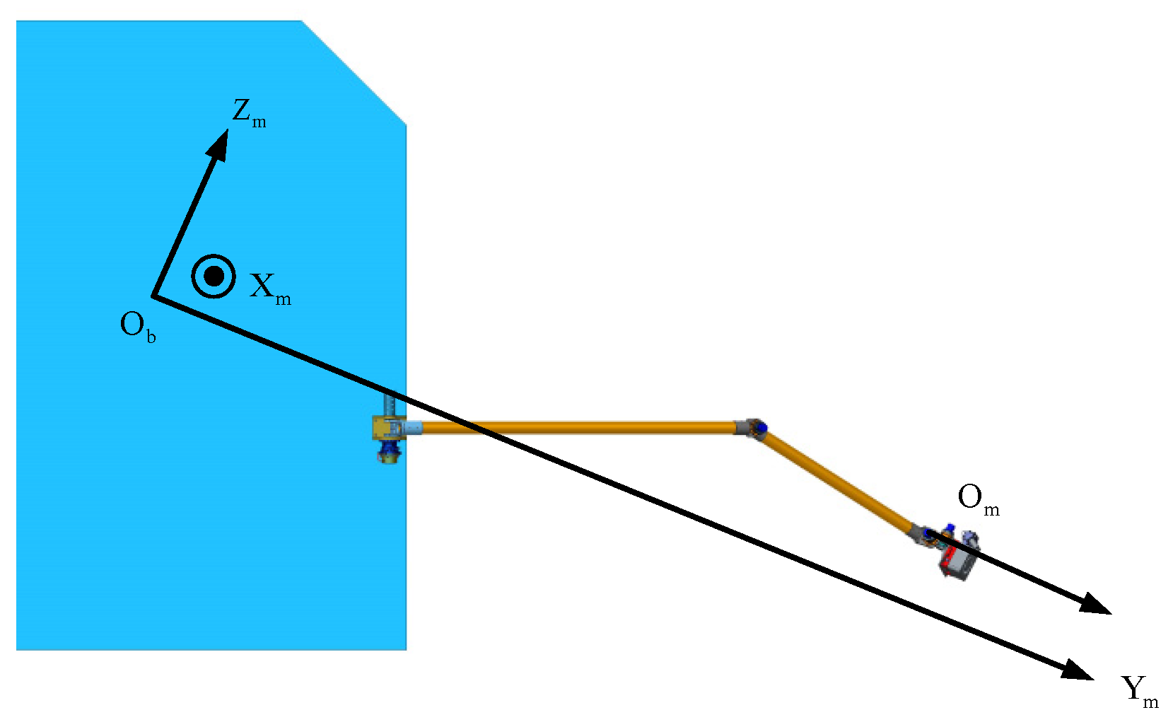
2.1.4. Mechanical Arm Coordinate System

When the angular momentum of the satellite is kept within a reasonable range in any coordinate system, the angular momentum of the satellite can be unloaded. However, due to the uncertainty of propulsion direction used for position keeping each time, it is complicated to describe the direction of EP during angular momentum unloading in fixed coordinates such as the J2000 coordinate system, radial coordinate system, nominal coordinate system, or satellite body coordinate system. In order to facilitate the analysis of the EP direction, the concept of a “mechanical arm coordinate system O b X m Y m Z m ” is introduced. It is defined as follows: the origin of the mechanical arm coordinate system is located at the center of mass O b of the satellite, the position of propulsion action (center of rotation of the two wrist joints of the mechanical arm) is defined as O m , and the Y m axis of the mechanical arm coordinate system points to the direction of thrust for SK, as shown in Figure 3.
The mechanical arm needs to complete the tasks of SK and angular momentum unloading while eliminating the influence of the three-axis attitude offset of the satellite. The coordinate system of the mechanical arm is a dynamic coordinate system, which is not only affected by the SK strategy, but also related to the offset attitude of the satellite. The attitude quaternion q im from the J2000 coordinate system to the mechanical arm coordinate system is defined as:
q im = q is q sm
where q sm is the attitude quaternion from the nominal coordinate system to the mechanical arm coordinate system:
q sm = [ cos ( θ t / 2 ) 0 0 sin ( θ t / 2 ) ] [ cos ( θ r / 2 ) sin ( θ r / 2 ) 0 0 ]
where θ t is the deflection angle of the EP direction along the Z s axis of the nominal coordinate system:
θ t = arcsin Δ v t Δ v n
When the satellite is flying forward, Δ v t < 0 , Δ v n > 0 , so θ t < 0 . This shows that when the satellite is flying forward, the axis Y m of the mechanical arm coordinate system is obtained by the negative rotation of the Y s axis of the nominal coordinate system around the Z s axis, and the mechanical arm is close to the X s side of the nominal coordinate system. On the contrary, when the satellite is flying backward, Δ v t < 0 , Δ v n < 0 , so θ t < 0 . This shows that when the satellite is flying forward, the axis Y m of the mechanical arm coordinate system is obtained by the positive rotation of the Y s axis of the nominal coordinate system around the Z s axis, and the mechanical arm is close to the X s side of the nominal coordinate system. In Equation (6), θ r is the deflection angle of the direction of EP along the X s axis of the nominal coordinate system:
θ r = arcsin Δ v r S ψ Δ v n = arcsin Δ v r | Δ v n |
The deflection angle of the EP is small, so the three axes of the mechanical arm coordinate system are roughly the same as the three axes of the nominal coordinate system. In Equation (5), both θ r and θ t are small angles, and the effect of rotation can be ignored in engineering, so Equation (5) can also be written as:
q sm = [ cos ( θ r / 2 ) sin ( θ r / 2 ) 0 0 ] [ cos ( θ t / 2 ) 0 0 sin ( θ t / 2 ) ]

2.2. Strategy of Unloading Angular Momentum

For GEO satellites with solar panels tracking the sun, the panels are arranged on the north and south sides of the satellite. If the satellite adopts a single-wing sail configuration, under the influence of solar pressure, the angular momentum accumulated in the X b O b Z b plane of the satellite can reach about 40 Nms per day, but the angular momentum accumulated in the satellite ± Y b direction is generally less than 1 Nms per day. Therefore, for asymmetric GEO satellites with all-EP, angular momentum unloading is required every day. This means that SK control needs to be performed for a long time each day to achieve the large daily angular momentum offloading requirements.
The semi-major axis of the GEO satellite is about 42,000 km, while the diameter of the Earth is less than 13,000 km. Therefore, the amount of rolling pitch attitude offset required for the satellite to point towards the target on the earth’s surface does not exceed 8.7°. The yaw axis attitude offset required for EWSK does not exceed 5°, and the combined influence of the two on the propulsion direction does not exceed 10°.
In this paper, the angular momentum of the satellite is unloaded by using the propulsion of SK. The unloading of angular momentum is mainly divided into two parts: the first is the large angular momentum unloading in the X m O m Z m plane of the mechanical arm coordinate system; The second is the small angular momentum unloading in the ± Y m direction of the satellite. The method of satellite angular momentum unloading by using propulsion of SK is shown in Figure 4.
Figure 4a is the X m O m Z m plane of the mechanical arm coordinate system. This plane will change as the position of the propulsion changes. O is the point of the satellite’s center of mass of projected on the X m O m Z m plane (referred to as the origin). h x z C is the angular momentum needed to be unloaded of the satellite in the X m O m Z m plane of the mechanical arm coordinate system. M is the corresponding propulsion position during angular momentum unloading, and it is also the central position of the EP line movement (referred to as the equivalent position). The direction of OM is the cross of h x z C and Y m . Assuming that the thrust direction is constant along Y m , when the thrust position is M, the unloading amount of angular momentum during the specified SK time is h x z C .
As can be seen from Figure 4a, if the propulsion direction is not changed, the angular momentum in the Y m direction under the mechanical arm coordinate system cannot be unloaded. When h x z C is not affected as much as possible, the angular momentum unloading in the Y m direction of the mechanical arm coordinate system can be achieved by slightly changing the thrust position and direction at the same time. Specific methods are as follows:
Take any line that goes through M. On this line, two points, A and B, are taken with M as the center, where A is the initial state of the mechanical arm (referred to as initial state A) and B is the final state of the mechanical arm (referred to as final state B). Line MA is the result of line OM rotating β h around the Y m axis. Vectors AC and BD are perpendicular to line AB. Point C is the projection point in the X m O m Z m plane after the propulsion direction of point A is deflected. Point D is the projection point in the X m O m Z m plane after the propulsion direction of point B is deflected. Vectors AC and BD are the direction in which the Y m axis component of propulsion deflected around line AB. Figure 4b shows the three-dimensional space formed before and after the direction change of the thruster. The meaning of the letters in Figure 4b is the same as that in Figure 4a. Vector AC is obtained by Y m rotating θ m y around line BA at the starting position A. Vector BD is obtained by Y m rotating θ m y around line AB at the final state B.
Assuming that the magnitude F of the propulsion generated by the EP is constant, the length of time that the end of the mechanical arm is in the initial state A and the final state B is the same. In this way, when unloading angular momentum along the Y m direction, there is almost no disturbed angular momentum in the X m and Z m axis. Thus, in order to unload the angular momentum in the Y direction, the position and direction of the end of the mechanical arm are switched between states A and B during the operation of the EP (the position of the EP is switched between A and B, and the direction of the EP is switched between vectors AC and BD).
In the case of the same unloading torque, it is expected that the movement range of the end of the mechanical arm is as small as possible, that is, the minimum value of max ( | O A | , | O B | ) is required. | O A | and | O B | are, respectively:
| O A | = | A M | 2 + | O M | 2 + 2 | A M | | O M | cos β h | O B | = | B M | 2 + | O M | 2 2 | B M | | O M | cos β h
Then
max ( | O A | , | O B | ) = { | A M | 2 + | O M | 2 + 2 | A M | | O M | cos β h π / 2 β h π / 2 | A M | 2 + | O M | 2 2 | A M | | O M | cos β h β h > π / 2 , β h < π / 2
According to Equation (11), it can be seen that when β h = ± π / 2 , max ( | O A | , | O B | ) is the smallest, and the movement range of the end of the mechanical arm is the smallest. Therefore, in subsequent calculations, take β h = ± π / 2 .
R O M is the maximum value of vector OM. R O A is the maximum value of vector OA when β h = ± π / 2 . It is also the shortest distance between the end of the mechanical arm and the Y m axis of the mechanical arm coordinate system when the angular momentum is unloaded. Therefore, the maximum arm of force R A M for angular momentum unloading in the ± Y m direction is:
R A M = R O A 2 R O M 2
It can be seen from Equation (11) that when R O A is constant, the longer R O M is, the shorter R A M is. In engineering, appropriate control parameters of angular momentum unloading are selected according to the law of angular momentum variation of satellite.
Let θ m y MAX be the maximum deflection angle of EP during angular momentum unloading in the Y m direction. Then, the ratio of the component d m y of the arm of force in the Y m axis generated by angular momentum unloading to the absolute value | θ m y | of the deflection angle of the EP is satisfied by Equation (12). It can be seen that the component d m y of the arm of force in the Y m axis generated by angular momentum unloading increases linearly as the absolute value | θ m y | of the deflection angle of the EP increases.
k H y d m y | θ m y | = R A M θ m y MAX
However, when unloading angular momentum in the Y m direction, the change in propulsion direction will cause the perturbed moment of force in the AB direction, as shown in Figure 5.
The definition of AB in Figure 5 is consistent with that in Figure 4. In Figure 5a, the thrust vector of the EP is at the initial state A. The effective arm of force corresponding to the unloading moment of force T 1 A generated by force F in the Y m direction is r 1 A . The perturbed arm of force corresponding to the unloading moment of force T 2 A generated by force F in the AB direction is r 2 A . In Figure 5b, the thrust vector of the EP is at the terminal state B. The effective arm of force corresponding to the unloading moment of force T 1 B generated by force F in the Y m direction is r 1 B . The perturbed arm of force corresponding to the unloading moment of force T 2 B generated by force F in the AB direction is r 2 B .
In the two states A and B, the unloading moment of force T 1 A and T 1 B at A and B are in the same direction and superimposed on each other, respectively. T 2 A and T 2 B are equal in size and opposite in direction, and the resulting perturbed moment of force can cancel each other out in a complete unloading process. Therefore, the unloading moment of force only exists in the Y m direction. It is worth noting that for the condition T 2 A = T 2 B to hold, the component of the distance in the Y m direction between the EP and the satellite center of mass must remain constant during the motion of the mechanical arm in the direction AB.
Since the perturbed moment of force T 2 A and T 2 B are larger than the angular momentum unloading moment of force of the X m O m Z m plane, the angular momentum of the satellite in the X m O m Z m plane may be out of tolerance during the unloading process. The solution to this problem is to reduce the single accumulation time of the perturbed moment of force of axis A and B by increasing the switching times n H y ( n H y 1 ) between the A, B states of the mechanical arm, and then reduce the contribution of the perturbed moment of force A and B to the angular momentum of the X m O m Z m plane. The greater the unloading angular momentum required in the Y m direction, the greater the corresponding n H y . However, the perturbed moment of force corresponding to states A and B are opposite in direction but unequal in magnitude, which will affect the angular momentum unloading effect of the X m O m Z m plane and need to be eliminated by the next angular momentum unloading.

2.3. Position and Attitude Calculation of EP with a Mechanical Arm

2.3.1. Connection between EP and a Mechanical Arm

The thrust generated by the EP can be equivalent to the direction of the thrust. The thrust direction passes through the center of the EP, and it can be considered that the equivalent installation position of the EP is on the line of the thrust direction, as shown in Figure 6.
The installation position of the EP is the intersection of the following two lines: ① Thrust vector generated by EP; ② The vertical line between thrust and the rotation axis of the end joint of the robotic arm. If the direction of the EP intersects the rotation axis of the end joint of the robotic arm, the intersection point is the equivalent installation position of the EP. Therefore, the position and attitude control of the end of the robotic arm are decoupled. In addition, the control of the robotic arm has nothing to do with the innovation of this paper, so the relevant content is not explained.

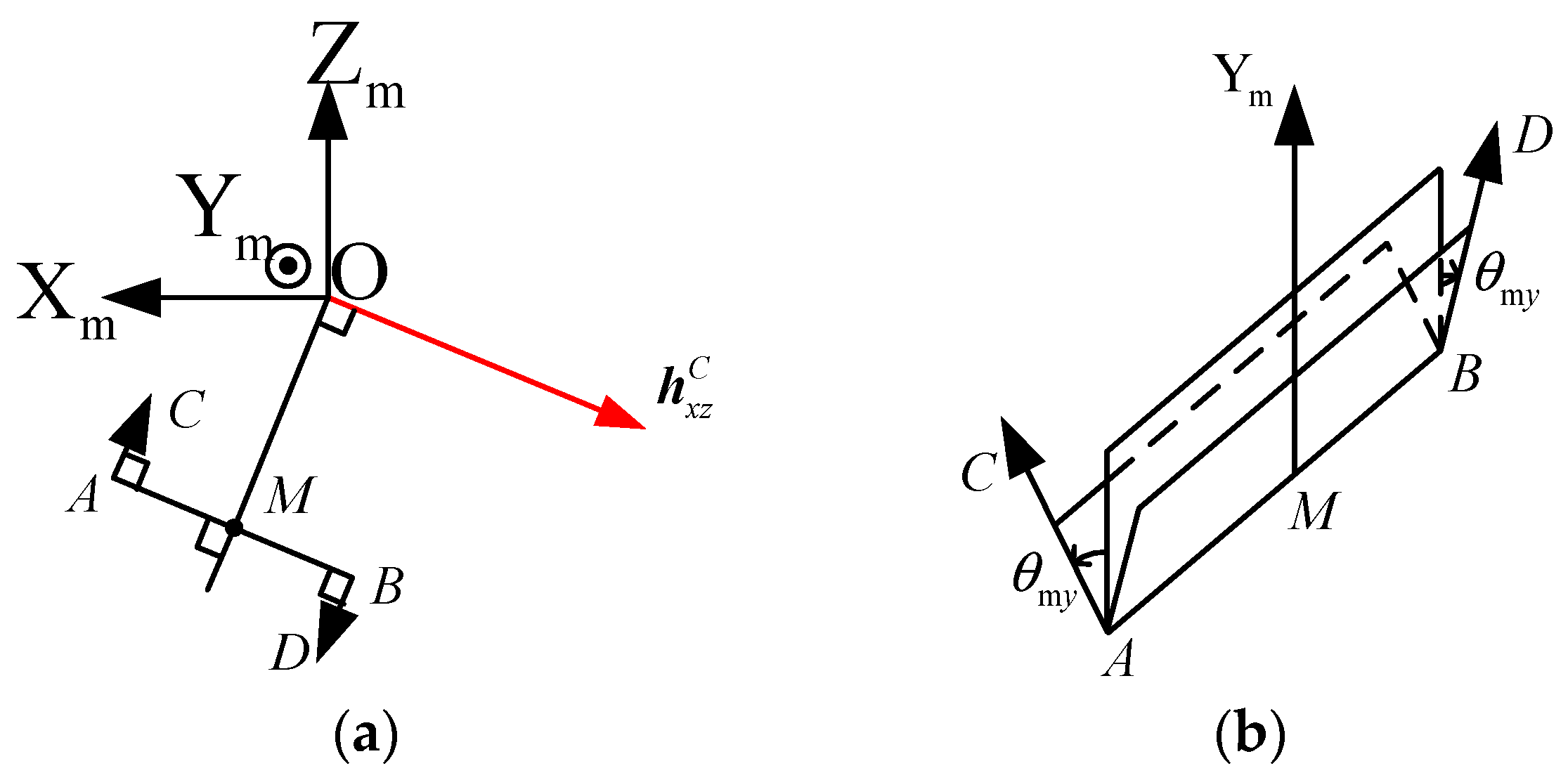
2.3.2. Position and Attitude Calculation of EP in the Mechanical Arm Coordinate System

In Figure 4, the coordinates ( x m M , z m M ) of point M in the X m O m Z m plane are
x m M = h m z C F t NS z m M = h m x C F t NS
where h m x C and h m z C are the components of h x z C on the X m axis and Z m axis of the mechanical arm coordinate system, respectively; t NS is the duration of orbital inclination keeping using EP. The formula for h x z C is
h x z C [ h m x C h m y C h m z C ] = A m i [ h i x C h i y C h i z C ]
where A m i is the attitude transformation matrix from the J2000 coordinate system to the mechanical arm coordinate system. [ h i x C h i y C h i z C ] T is the angular momentum that needs to be unloaded of the satellite in the J2000 coordinate system. Its calculation formula is
[ h i x C h i y C h i z C ] = [ 0.5 T h ˙ i x H i x 0.5 T h ˙ i y H i y 0.5 T h ˙ i z H i z ]
where [ h ˙ i x h ˙ i y h ˙ i z ] T is the perturbed moment of force of the satellite in the J2000 coordinate system.
In order to make the angular momentum before and after unloading evenly distributed in center zero as far as possible, it is necessary to calculate the angular momentum to be unloaded in the way of “negative offset”. As shown in Figure 7, Point A is the angular momentum of the satellite in the J2000 coordinate system when the angular momentum unloading strategy is generated. Point C is the angular momentum of the satellite in the J2000 coordinate system under the action of perturbed moment of force of solar light pressure. O is the desired angular momentum envelope center. Point D is the angular momentum that needs to be unloaded this time. AC and DO are the direction of solar pressure perturbed moment of force. When the angular momentum is unloaded to point D, under the action of perturbed moment of force of the solar pressure, the angular momentum of the satellite will pass through point O, and the trajectory of the angular momentum will be evenly distributed at both ends of point O.
Assuming that the satellite is equipped with a single-wing solar panel, because the center of solar pressure of the satellite does not coincide with the center of mass of the satellite, the solar panel of the satellite continues to point to the sun, which will produce approximately constant perturbed moment of force under the action of solar light pressure. Since the sun moves periodically in the J2000 coordinate system, the perturbed moment of force also changes periodically. Therefore, [ h ˙ i x h ˙ i y h ˙ i z ] T in Equation (15) can be regarded as a constant value in a short period of time, and its calculation is as follows:
[ h ˙ i x h ˙ i y h ˙ i z ] = { T P S ψ > 0 T P S ψ < 0
where T P is the perturbed moment of force of solar light pressure in the J2000 coordinate system when the satellite is flying forward. T P is the perturbed moment of force of solar light pressure in the J2000 coordinate system when the satellite is flying backward, and T P = T P . In Equation (15), [ H i x H i y H i z ] T is the angular momentum of the satellite in the J2000 coordinate system. Its calculation formula is as follows:
[ H i x H i y H i z ] = A ib [ H b x 0 H b y 0 H b z 0 ] + [ h ˙ i x h ˙ i y h ˙ i z ] Δ t h
where A ib is the attitude transformation matrix from the satellite body coordinate system to the J2000 coordinate system. [ H b x 0 H b y 0 H b z 0 ] T is the angular momentum of the satellite in the satellite body coordinate system when the angular momentum unloading strategy is generated. Δ t h is the time difference between the time when the angular momentum unloading strategy is generated and the intermediate time when the next SK pulse is applied. Its calculation formula is
Δ t h = mod ( λ tm λ , 2 π ) n
where λ tm is the orbital right ascension corresponding to the midpoint of EP operation. λ is the orbital right ascension at the time when the angular momentum unloading strategy is generated. n is the average orbital angular velocity.
Considering the limited range of motion of the end of the mechanical arm, Equation (13) can be written as:
x m M = h m z C min ( ( h m z C ) 2 + ( h m x C ) 2 , F t N S R O M ) F t NS ( h m z C ) 2 + ( h m x C ) 2 z m M = h m x C min ( ( h m z C ) 2 + ( h m x C ) 2 , F t N S R O M ) F t NS ( h m z C ) 2 + ( h m x C ) 2
The electric thrust deflection angle θ m y is calculated as follows:
θ m y = sgn ( h m y C ) h m y C k H y F t NS
where h m y C is the unloading angular momentum in the Y m direction.
The value range of θ m y is θ m y ( 90 ° , 90 ° ) . The polarity of θ m y indicates the direction of EP. For example, when θ m y > 0 , it means that the EP rotates positively along the MA direction at point A, and the EP rotates positively along the MB direction at point B. In specific applications, θ m y should be limited to an appropriate range according to actual engineering constraints. Formula (20) can be written as:
θ m y = { sgn ( h m y C ) h m y C / ( k H y F t NS ) h m y C / ( k H y F t NS ) θ myMAX sgn ( h m y C ) θ m y MAX h m y C / ( k H y F t NS ) > θ myMAX
θ myMAX is the maximum value of the electric deflection angle when the angular momentum in the direction Y m is unloaded, which is positive.
In Figure 4, the coordinates ( x m A , z m A ) of point A in the X m O m Z m plane in the mechanical arm coordinate system are
x m A = x m M k H y | θ m y | sin β h z m A = z m M k H y | θ m y | cos β h
The coordinates ( x m B , z m B ) of point B in the X m O m Z m plane in the mechanical arm coordinate system are
x m B = x m M + k H y | θ m y | sin β h z m B = z m M + k H y | θ m y | cos β h
The unit vector V m A of A in the mechanical arm system is
V m A = cos θ m y V m 0 + ( 1 cos θ m y ) ( V m M A V m 0 ) V m M A + sin θ m y ( V m M A × V m 0 )
where V m 0 = ( 0 1 0 ) T is the initial direction of the EP in the mechanical arm coordinate system. The expression for V m M A is:
V m M A = [ sin ( π 2 + β h 0 ) 0 cos ( π 2 + β h 0 ) ]
where β h 0 is the angle between OZ m and OM in the X m O m Z m plane, expressed as:
β h 0 = { arctan ( h m x C / h m z C ) h m z C > 0 π + arctan ( h m x C / h m z C ) h m z C < 0 0 h m z C = 0
The unit vector V m B of B in the mechanical arm system is
V m B = cos θ m y V m 0 + ( 1 cos θ m y ) ( V m M B V m 0 ) V m M B + sin θ m y ( V m M B × V m 0 )
where
V m M B = V m M A

2.3.3. Position and Attitude Calculation of EP in the Satellite Body Coordinate System

In order to facilitate the simulation and evaluation of the motion range of the mechanical arm in the satellite body coordinate system, the position and attitude of the EP in the satellite body coordinate system should also be calculated. The coordinates ( x b A , z b A ) of point A in the X b O b Z b plane in the satellite body coordinate system are
( x b A y b A z b A ) = ( A mb ) 1 ( x m A 0 z m A )
The coordinates ( x b B , z b B ) of point B in the X b O b Z b plane in the satellite body coordinate system are
( x b B y b B z b B ) = ( A mb ) 1 ( x m B 0 z m B )
The unit vector V b A of A in the satellite body coordinate system is:
V b A = ( A mb ) 1 V m A
The unit vector V b B of B in the satellite body coordinate system is:
V b B = ( A mb ) 1 V m B
In Equations (29)–(32), A mb is the attitude transfer matrix from the mechanical arm coordinate system to the satellite body coordinate system.

2.4. Angular Momentum Unloading in the Case of Attitude Offset

In general, when the satellite has a three-axis attitude offset (attitude maneuver can also be regarded as attitude offset), the direction of thrust used for SK will also be offset. In this paper, a mechanical arm carrying electric thrust is used to control the thrust direction as expected during the three-axis attitude offset.
Take the GEO satellite’s Z axis pointing to the center of the earth as an example. The diagrams of a satellite pointing at a target on the earth’s surface as it is flying forward and backward are shown in Figure 8 and Figure 9, respectively.
Assume that the earth is a standard spherical sphere (without considering the oblate of the earth), O is the center of the earth, B is the object to be observed on the earth’s surface, O b is the center of mass of the satellite, X s , Y s , Z s are, respectively, the three-axis direction of the nominal coordinate system, ϕ is the latitude of the object to be observed on the earth’s surface, and Δ λ is the relative longitude between the object to be observed on the earth’s surface and the satellite’s subsatellite point.
When the Z b axis of the satellite body coordinate system points to the ground target B, its three-axis coordinate system can be regarded as the satellite rotating γ from the nominal coordinate system around the space line O b A . The direction of line O b A is:
O b A = O b O × O B
In the satellite body coordinate system, the expression of O b O is:
O b O = [ 0 0 a ]
In the satellite body coordinate system, the expression of O B is:
O B = [ r e cos ϕ sin Δ λ r e sin ϕ r e cos ϕ cos Δ λ ]
Substitute O b O and O B into Formula (9) to obtain
O b A = [ a r e sin ϕ a r e cos ϕ sin Δ λ 0 ]
In the satellite body coordinate system, the expression of O b B is:
O b B = [ r e cos ϕ sin Δ λ r e sin ϕ a r e cos ϕ cos Δ λ ]
According to the law of cosine, γ can be calculated as:
γ = arccos | O b O | 2 + | O b B | 2 | O B | 2 2 | O b O | | O b B |
The attitude quaternion q sb from the nominal coordinate system to the satellite body coordinate system is
q sb = [ cos γ 2 sin ϕ ( sin ϕ ) 2 + ( cos ϕ sin Δ λ ) 2 sin γ 2 cos ϕ sin Δ λ ( sin ϕ ) 2 + ( cos ϕ sin Δ λ ) 2 sin γ 2 0 ]
By combining Equations (1) and (39), the attitude quaternion q ob from the satellite orbital coordinate system to the body coordinate system can be obtained as follows:
q ob = { [ cos γ 2 sin ϕ ( sin ϕ ) 2 + ( cos ϕ sin Δ λ ) 2 sin γ 2 cos ϕ sin Δ λ ( sin ϕ ) 2 + ( cos ϕ sin Δ λ ) 2 sin γ 2 0 ] S ψ > 0 [ 0 cos ϕ sin Δ λ ( sin ϕ ) 2 + ( cos ϕ sin Δ λ ) 2 sin γ 2 sin ϕ ( sin ϕ ) 2 + ( cos ϕ sin Δ λ ) 2 sin γ 2 cos γ 2 ] S ψ < 0
In the nominal coordinate system, the three-axis attitude of the satellite is the corresponding nominal forward or backward flight attitude. Therefore, angular momentum unloading can be accomplished by executing the SK strategy [16,17,18] in the nominal coordinate system. The conversion matrix from the nominal coordinate system to the satellite body coordinate system is the conversion matrix of the satellite attitude offset. Therefore, the attitude quaternion q bm from the satellite body coordinate system to the mechanical arm coordinate system is:
q bm = q bo q om = q ob 1 q om
where q om is the attitude quaternion from the orbital coordinate system to the mechanical arm coordinate system:
q om = q io 1 q im
In addition, q bm can also be used to convert the angular momentum of the satellite body coordinate system to the mechanical arm coordinate system and then unload the satellite angular momentum under the mechanical arm coordinate system.
The above method can be applied to any satellite attitude within the reach range of the mechanical arm. The attitude maneuver can be regarded as a special attitude offset (that is, the attitude angle of the satellite is continuously offset), so the method in this paper is also applicable to the angular momentum unloading during the attitude maneuver.

2.5. Fuel Consumption Analysis for Angular Momentum Unloading

The angular momentum unloading strategy adopted in this paper is as follows: in an SK arc, the position and attitude of the EP are changed by the mechanical arm, and the unloading torque in the Y m direction is generated by the SK, so as to realize the angular momentum unloading of the satellite. Therefore, the deflection angle θ m y of the EP determines the efficiency of SK. The smaller the absolute value of the deflection angle, the smaller the loss of thrust for SK.
Take | θ m y | = 5 as an example, then the efficiency of thrust is cos θ m y = 0.9962 . As a result, the loss of SK efficiency due to angular momentum unloading is at most 0.4%. According to the literature [16,17,18], the annual speed increment required for SK does not exceed 50 m/s. As a result, the required velocity increment for angular momentum unloading is less than 0.2 m/s per year.

3. Simulation Result

According to the analysis in Section 4, in order to completely cancel the perturbed moment of force generated in states A and B in Figure 5, the perturbed moment of force at A and B are required to be equal in magnitude. This requires that the distance between the mechanical arm at point A y b A and the center of mass of the satellite and the distance between the mechanical arm at point B y b B and the center of mass of the satellite are equal during the process of moving the end of the mechanical arm. The larger y b A and y b B are, the larger the perturbed moment of force generated during angular momentum unloading. If y b A and y b B are too large, the angular momentum of the satellite is out of tolerance. Therefore, in the simulation, it can be assumed that both y b A and y b B are 4 m according to satellite configuration constraints. Suppose that the accumulated angular momentum in the Y b direction of the satellite body coordinate system is 2 Nms a day. Then, the angular momentum accumulated in the X b O b Z b plane of the satellite body coordinate system is about 46 Nms per day. Let θ myMAX = 5 , n H y = 3 , and other initial conditions for simulation are shown in Table 1.

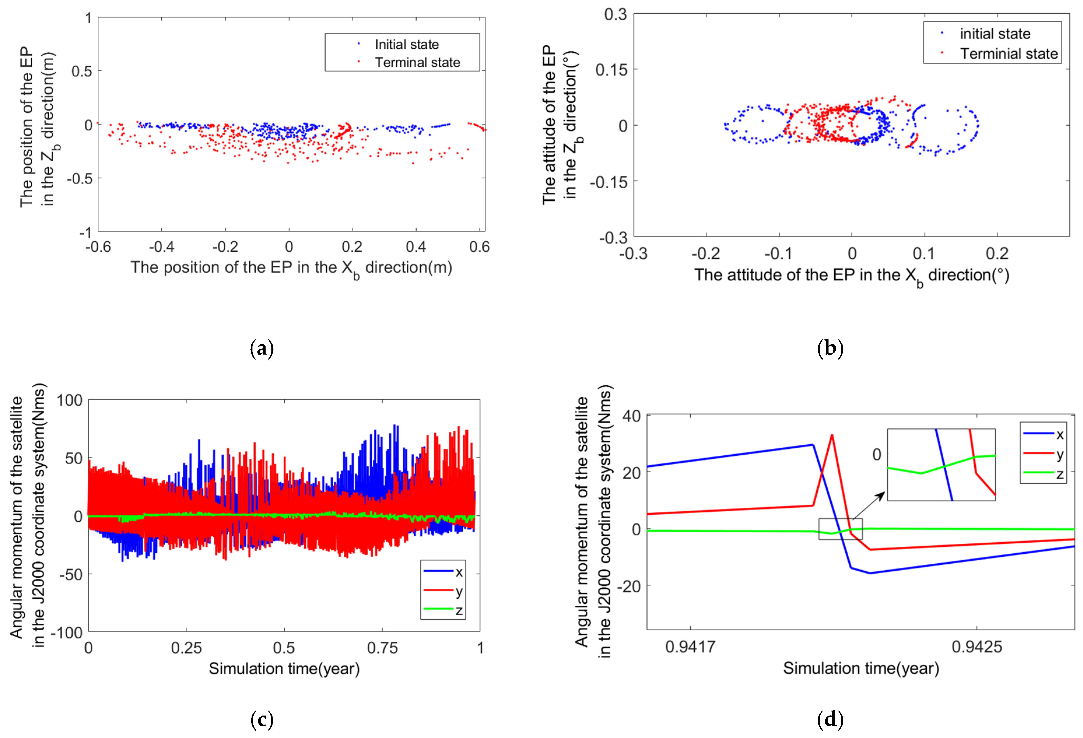
3.1. Simulation of Angular Momentum Unloading without Attitude Offset

The simulation results of angular momentum unloading without attitude offset are shown in Figure 10.
As can be seen from Figure 10a,b, the position of EP in the X b direction is ±0.60 m, and the position in the Z b direction is ±0.20 m. Assuming that the distance between the EP and the satellite’s center of mass is about 4 m, the EP is active in a square cone with the Y b axis as the central axis and the east–west semi-cone angle is about 8.5°, and the north–south semi-cone angle is about 2.8°. It can be seen from Figure 10c,d that the maximum value of the angular momentum amplitude of the satellite is 40 Nms, which proves that the strategy of angular momentum unloading proposed in this paper is effective.

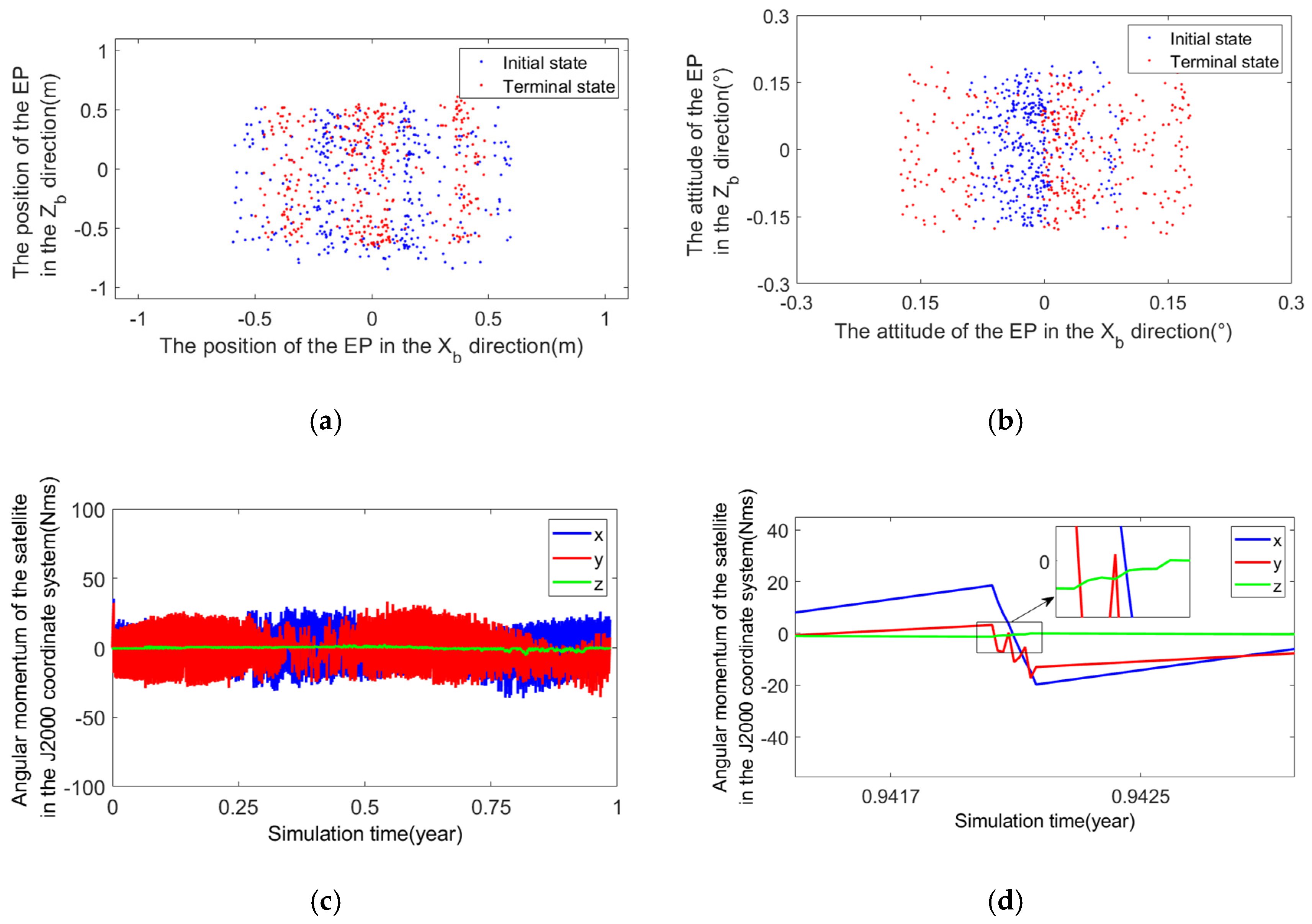
3.2. Simulation of Angular Momentum Unloading with Attitude Offset

The simulation results of angular momentum unloading without attitude offset are shown in Figure 11.
As can be seen from Figure 11a,b, the position of EP in the X b direction is ±0.60 m, and the position in the Z b direction is ±0.75 m. Assuming that the distance between the electric thrust and the satellite’s center of mass is about 4 m, the electric thrust is active in a square cone with the Y b axis as the central axis and the east–west semi-cone angle is about 8.5°, and the north–south semi-cone angle is about 10.6°. It can be seen from Figure 11c,d that the maximum value of the angular momentum amplitude of the satellite is 40 Nms, which proves that the strategy of angular momentum unloading proposed in this paper is effective.

4. Discussion

By comparing Figure 10a,b and Figure 11a,b, it can be seen that when the attitude is offset, the position and attitude range of the end of the robotic arm in the Z b direction of the satellite body coordinate system are significantly larger. This is because when the satellite is required to point to objects near the North and South poles, the attitude of the rolling axis of the satellite is offset, and the angular momentum unloading causes the position and attitude range of the EP in the Z b direction to become larger.
Due to fuel consumption and other reasons, the actual center of mass of the satellite will be different from the theoretical value. The deviation of the center of mass is generally distributed in a spherical region with a radius of about 0.01 m. When the angular momentum unloading is carried out with an electric push of 80 mN, the maximum thrust action time is 7688 s, and the deviation of angular momentum unloading is about 4.6 Nms. Generally, the angular momentum envelope capacity of large GEO satellites is above 50 Nms, so this deviation of angular momentum unloading can be ignored. The deviation of angular momentum unloading caused by the deviation of the center of mass is mainly manifested as the constant deviation of the center value of the angular momentum of the satellite, which reduces the safety margin of the angular momentum envelope of the satellite. Therefore, it is necessary to correct this deviation. There are two main methods of correction: First, the angular momentum unloading strategy is generated using the precise satellite’s center of mass. This method can completely solve the above problem of angular momentum unloading deviation. Generally, three-axis attitude control by chemical propulsion is used to achieve accurate estimation of the center of mass, but the method is not operable. Second, the target value of this angular momentum unloading can be obtained by using the results of the last angular momentum unloading. This method is relatively simple. However, with the change of seasons, the unloading deviation of angular momentum may have a yearly cycle change, and the target value of angular momentum unloading needs to be updated regularly.

5. Conclusions

This paper presents a method of angular momentum unloading using a mechanical arm with EP. In this method, the satellite can be unloaded with large angular momentum by using an electric thruster in one SK arc. The problems of weak angular momentum unloading capacity and high fuel consumption of all-electric GEO satellites are solved. At the same time, the method can realize angular momentum unloading under the attitude offset of the satellite, which is conducive to the continuous and high-quality operation of the load on board. When the demand for angular momentum unloading along the thrust direction increases, the angle from which the thrust direction deviates from the center direction increases.
The angular momentum unloading algorithm proposed in this paper has a certain universality in the range of angular momentum unloading capacity. This will not only reduce the efficiency of SK but also cause the perturbed moment of force perpendicular to the thrust direction to increase, and the number of switching between the initial state and the final state will increase correspondingly. Therefore, the smaller the angular momentum unloading demand along the thrust direction, the better the adaptability of the angular momentum unloading scheme proposed in this paper.

Author Contributions

Methodology, H.Z., L.Y. and Q.Z.; software, L.Y.; writing—original draft preparation, C.L.; data curation, J.Q., H.Y. and F.L. All authors have read and agreed to the published version of the manuscript.

Funding

This research received no external funding.

Institutional Review Board Statement

Not applicable.

Informed Consent Statement

Not applicable.

Data Availability Statement

Data are contained within the article.

Conflicts of Interest

Author Hong Zhu was employed by the company Shanghai Aerospace Control Technology Institute. The remaining authors declare that the research was conducted in the absence of any commercial or financial relationships that could be construed as a potential conflict of interest.

References

  1. Walsh, A.; Cairano, D.; Weiss, A. MPC for coupled station keeping, attitude control, and momentum management of low-thrust geostationary satellites. In Proceedings of the 2016 Annual American Control Conference, Boston, MA, USA, 6–8 July 2016; pp. 7408–7413. [Google Scholar]
  2. Ma, X.; Han, D.; Tang, L. Research on angular momentum unloading of electric propulsion satellites. China Space Sci. Technol. 2016, 36, 70–76. [Google Scholar]
  3. Weiss, A.; Cairano, D. Station Keeping and Momentum Management of Low-thrust Satellites Using MPC. Aerosp. Sci. Technol. 2018, 76, 229–241. [Google Scholar] [CrossRef]
  4. Weiss, A.; Kalabic, U.; Cairano, S. Model Predictive Control for Simultaneous Station keeping and Momentum Management of Low-thrust Satellites. In Proceedings of the 2015 American Control Conference, Chicago, IL, USA, 1–3 July 2015; pp. 2305–2310. [Google Scholar]
  5. Li, C.; Xu, B.; Zhou, W.; Peng, Q. Geostationary station-keeping of electric-propulsion satellite equipped with robotic arms. Aerospace 2022, 9, 182. [Google Scholar] [CrossRef]
  6. Frederik, J.; Bruijn, D. Geostationary Satellite Station-Keeping Using Convex Optimization. J. Guid. Control Dyn. 2015, 39, 605–616. [Google Scholar]
  7. Gazzino, C.; Arzelier, D.; Cerri, L.; Losa, D.; Louembet, C.; Pittet, C. A Three-step Decomposition Method for Solving the Minimum-fuel Geostationary Station Keeping of Satellites Equipped with Electric Propulsion. Acta Astronatica 2019, 158, 12–22. [Google Scholar] [CrossRef]
  8. Gazzino, C.; Arzelier, D.; Losa, D.; Louembet, C.; Pittet, C.; Cerri, L. Optimal Control for Minimum-fuel Geostationary Station Keeping of Satellites Equipped with Electric Propulsion. IFAC PapersOnLine 2016, 49, 379–384. [Google Scholar] [CrossRef]
  9. Gazzino, C.; Louembet, C.; Arzelier, D.; Jozefowiez, N.; Losa, D.; Cerri, C.P. Interger Programming for Optimal Control of Geostationary Station Keeping of Low-thrust Satellites. In Proceedings of the 20th IFAC World Congress 2017, Toulouse, France, 9–14 July 2017. [Google Scholar]
  10. Ye, L.; Wang, J.; Baoyin, H. Constellation maintenance and capture of sun-synchronous frozen orbits. Space Control Technol. Appl. 2021, 47, 24–32. [Google Scholar]
  11. Sukhanov, A.A.; Prado, A.F. On one Approach to the Optimization of Low-thrust Station Keeping Manoeuvres. Adv. Space Res. 2012, 50, 1478–1488. [Google Scholar] [CrossRef]
  12. Roth, M. Strategies for Geostationary Spacecraft Orbit SK Using Electrical Propulsion Only. Ph.D. Thesis, Czech Technical University, Prague, Czech Republic, 2020. [Google Scholar]
  13. Ogawa, N.; Terui, F.; Mimasu, Y.; Yoshikawa, K.; Ono, G.; Yasuda, S.; Matsushima, K.; Masuda, T.; Hihara, H.; Sano, J.; et al. Image-based autonomous navigation of Hayabusa2 using artificial landmarks: The design and brief in-flight results of the first landing on asteroid Ryugu. Astrodyn 2020, 4, 89–103. [Google Scholar] [CrossRef]
  14. Wang, Y.; Xu, S. Non-equatorial equilibrium points around an asteroid with gravitational orbit-attitude coupling perturbation. Astrodyn 2020, 4, 1–16. [Google Scholar] [CrossRef]
  15. Zhang, T.J.; Wolz, D.; Shen, H.X.; Luo, Y.-Z. Spanning tree trajectory optimization in the galaxy space. Astrodyn 2021, 5, 27–37. [Google Scholar] [CrossRef]
  16. Ye, L.; Liu, C.; Zhu, W.; Yin, H.; Liu, F.; Baoyin, H. North/south Station Keeping of the GEO Satellites in Asymmetric Configuration by Electric Propulsion with Manipulator. Mathematics 2022, 10, 2340. [Google Scholar] [CrossRef]
  17. Liu, F.; Ye, L.; Liu, C.; Wang, J.; Yin, H. Micro-thrust, Low-fuel Consumption, and High-precision East/west Station Keeping for GEO Satellites based on Synovial Variable Structure Control. Mathematics 2023, 11, 705. [Google Scholar] [CrossRef]
  18. Ye, L.; Liu, C.; Liu, F.; Yin, H.; Zhang, W.; Baoyin, H. The Low Fuel Consumption Keeping Method of Eccentricity under Integrated Keeping of Inclination-Longitude. Aerospace 2023, 10, 135. [Google Scholar] [CrossRef]
Figure 1. Satellite orbital coordinate system.
Aerospace 11 00290 g001
Figure 2. The layout scheme of electric thrust with a mechanical arm.
Aerospace 11 00290 g002
Figure 3. Schematic diagram of the mechanical arm coordinate system.
Aerospace 11 00290 g003
Figure 4. Schematic diagram of angular momentum unloading using EP with a mechanical arm. (a) X m O m Z m plane of the mechanical arm coordinate system, (b) Three-dimensional space formed before and after the direction change of the thruster.
Aerospace 11 00290 g004
Figure 5. Schematic diagram of angular momentum unloading and disturbance torque. (a) The thrust vector of the EP is at the initial state A, (b) The thrust vector of the EP is at the terminal state B.
Aerospace 11 00290 g005
Figure 6. Connection between EP and a mechanical arm.
Aerospace 11 00290 g006
Figure 7. Diagram of angular momentum to be unloaded.
Aerospace 11 00290 g007
Figure 8. The diagram of a satellite pointing at a target on the earth’s surface as it is flying forward.
Aerospace 11 00290 g008
Figure 9. The diagram of a satellite pointing at a target on the earth’s surface as it is flying backward.
Aerospace 11 00290 g009
Figure 10. The simulation results of angular momentum unloading without attitude offset. (a) The position of the EP in the satellite body coordinate system, (b) The attitude of the EP in the satellite body coordinate system, (c) Angular momentum of the satellite in the J2000 coordinate system, (d) Enlarged view of the angular momentum of the satellite in the J2000 coordinate system.
Aerospace 11 00290 g010
Figure 11. The simulation results of angular momentum unloading with attitude offset. (a) The position of the EP in the satellite body coordinate system, (b) The attitude of the EP in the satellite body coordinate system, (c) Angular momentum of the satellite in the J2000 coordinate system, (d) Enlarged view of the angular momentum of the satellite in the J2000 coordinate system.
Aerospace 11 00290 g011
Table 1. Orbital parameters used in simulation.
NameParameter
Coordinate SystemJ2000 Coordinate System
Orbital Epoch T 0 (UTC)1 August 2025 12:00:00
Semi-major Axis a (km)42,166.3
Eccentricity e 0.0001
Inclination i (°)0.08
Argument of Perigee ω (°)0
RAAN Ω (°)359.989
Mean Anomaly M (°)251.361
Mean Longitude l (°)121.019
Mass of Satellite m (kg)3000
Solar   Luminous   Pressure   Coefficient   C R 1.3
Disclaimer/Publisher’s Note: The statements, opinions and data contained in all publications are solely those of the individual author(s) and contributor(s) and not of MDPI and/or the editor(s). MDPI and/or the editor(s) disclaim responsibility for any injury to people or property resulting from any ideas, methods, instructions or products referred to in the content.

