Article

Collaborative Localization Method Based on Hybrid Network for Aerial Swarm

Navigation Research Center, College of Automation Engineering, Nanjing University of Aeronautics and Astronautics, Nanjing 211106, China
*
Author to whom correspondence should be addressed.
Aerospace 2024, 11(4), 304; https://doi.org/10.3390/aerospace11040304
Submission received: 2 February 2024 / Revised: 7 April 2024 / Accepted: 10 April 2024 / Published: 12 April 2024

Abstract

:
In light of the satellite rejection environment and how aircraft can obtain high-precision positioning, this paper proposes a collaborative correction algorithm for aircraft based on the rank-defect network. Aiming at the problem of insufficient anchor points, which result in insufficient observations and the divergence of aircraft inertial navigation errors, this algorithm can effectively improve the navigation performance of cluster aircraft. On the basis of the observation information provided by the anchor aircraft, the observation information between aircraft is fully utilized to improve the observability of the aircraft cluster positioning method. At the same time, the pseudo-observation equation of heterogeneous aircraft cluster positioning is introduced, and the divergence of inertial navigation positioning errors caused by insufficient observations is suppressed by the pseudo-observation solution. On the basis of introducing the pseudo-observation equation, the inertial navigation error is solved and corrected by the Newton iterative method and the divergence of the inertial navigation position error is restrained. Compared with an aircraft cluster positioning method that does not use the inertial navigation error co-correction based on the pseudo-observation solution, this paper can achieve better overall cluster positioning accuracy when the available observations are insufficient, which is suitable for practical applications.

1. Introduction

With the development of the Information Age, the application of UAVs is more and more extensive. At the same time, the cluster network composed of multiple UAVs also has very broad application prospects [1].
The initial research on the cluster collaboration algorithm mainly focused on maritime navigation [2], and subsequent research expanded to the ground [3] and air [4]. In an environment with weak satellite signals, it is difficult to obtain accurate GNSS positioning, so the overall performance of navigation is improved through the collaboration algorithm. Xie [5], Zhang [6], and Nicholson [7] used underwater sonar to transmit information, obtain information between multiple unmanned ships, and fuse it with the information obtained by the sensors of the unmanned ships themselves, estimate the position of the unmanned ships, and effectively improve the navigation accuracy. Zhang [8] and Santiago [9] considered the impact of ocean currents on the unmanned ship cooperative positioning algorithm and improved the algorithm using the ocean current information received by the main unmanned ship. Feng [10] and Qi [11] considered the delay of underwater communication and effectively solved the problem of communication delay by improving the algorithm. Hu [12] studied the use of high-precision unmanned ship information and the relative distance information between unmanned ships for collaborative positioning, which effectively improved the dynamic positioning performance of unmanned ships. In the “two master and one slave” unmanned ship system, the distance between the master and slave unmanned ships is used to assist the position estimation of the slave unmanned ship [13], and all information are weighted and fused. Fortmann [14] and Sun [15] used factor graph theory to design an underwater unmanned ship cooperative navigation algorithm and verified that the positioning accuracy of the algorithm was higher than the extended Kalman. Chen [16], Liu [17], and Zhang [18] studied the indoor pedestrian positioning method, which is based on the premise that only one pedestrian can obtain GNSS positioning. Chen [16] used the distance information between pedestrians to suppress the divergence of other pedestrian inertial navigation positioning. Liu [17] and Zhang [18] used the particle filter algorithm and Kalman filter algorithm, respectively, to fuse the UWB ranging information and IMU information, which can effectively compensate for IMU errors. Zhao [19] aimed at the satellite rejection environment, added a pseudo satellite on the ground to assist with the vehicle positioning, and verified the navigation performance under static and dynamic conditions. When some GNSS nodes are missing, the system model is built based on the particle filter and track estimation principle, and the location of GNSS missing nodes is estimated based on the relative distance information between ground nodes [20].
At present, aircraft cluster networking mostly uses GNSS and inertial navigation for integrated navigation to determine the position information of each aircraft. There are still some defects that cannot be ignored when cooperating in air operations, that is, when GNSS signals are subject to strong electromagnetic interference or are even completely rejected [21,22], the accuracy of the positioning and navigation cannot meet the requirements. When the cluster aircraft is an unmanned aircraft, the above problems will be more acute. Liu [23] constructed the observation equation through the data link ranging information, estimated the missile position information using the weighted least squares, and effectively suppressed the divergence of inertial navigation. Liu [24] used the relative distance and relative motion between nodes (speed difference and path difference between nodes) to conduct missile formation and studied the impact of relative motion between nodes on the navigation performance of the missile system. Causa [25] used the parent UAV to assist the child UAV rejected by GNSS in positioning, and used the accuracy factor to predict the positioning accuracy of the child UAV. Wang [26] reconstructed the measurement equation using the ranging information of anchor and label aircraft, deduced the pseudo-observation equation, and estimated the positioning error using the least square method. Wang [27] proposed a collaborative navigation method based on partnership optimization for clustered aircraft and analyzed the impact of the equivalent ranging error on the optimization effect of a geometric configuration.
In this paper, based on the analysis of the rank-defect observation in the cluster network when the satellite is rejected, a distributed inertial navigation error cooperative correction scheme for heterogeneous multi-aircraft is proposed. Secondly, based on the cluster network positioning technology of aircraft mutual ranging and angle measurement, a distributed inertial navigation error co-correction model of heterogeneous multi-aircraft based on pseudo-observation was established, and a distributed inertial navigation error co-correction algorithm of heterogeneous multi-aircraft based on pseudo-observation was designed according to the characteristics of the model. Finally, the proposed algorithm was simulated and analyzed. The simulation results show that the distributed inertial navigation error correction algorithm based on pseudo-observation for heterogeneous multi-aircraft can effectively improve the overall navigation accuracy of the rank-defect network, and that the algorithm also significantly improves the navigation accuracy when the benchmark aircraft participates in the cooperation.

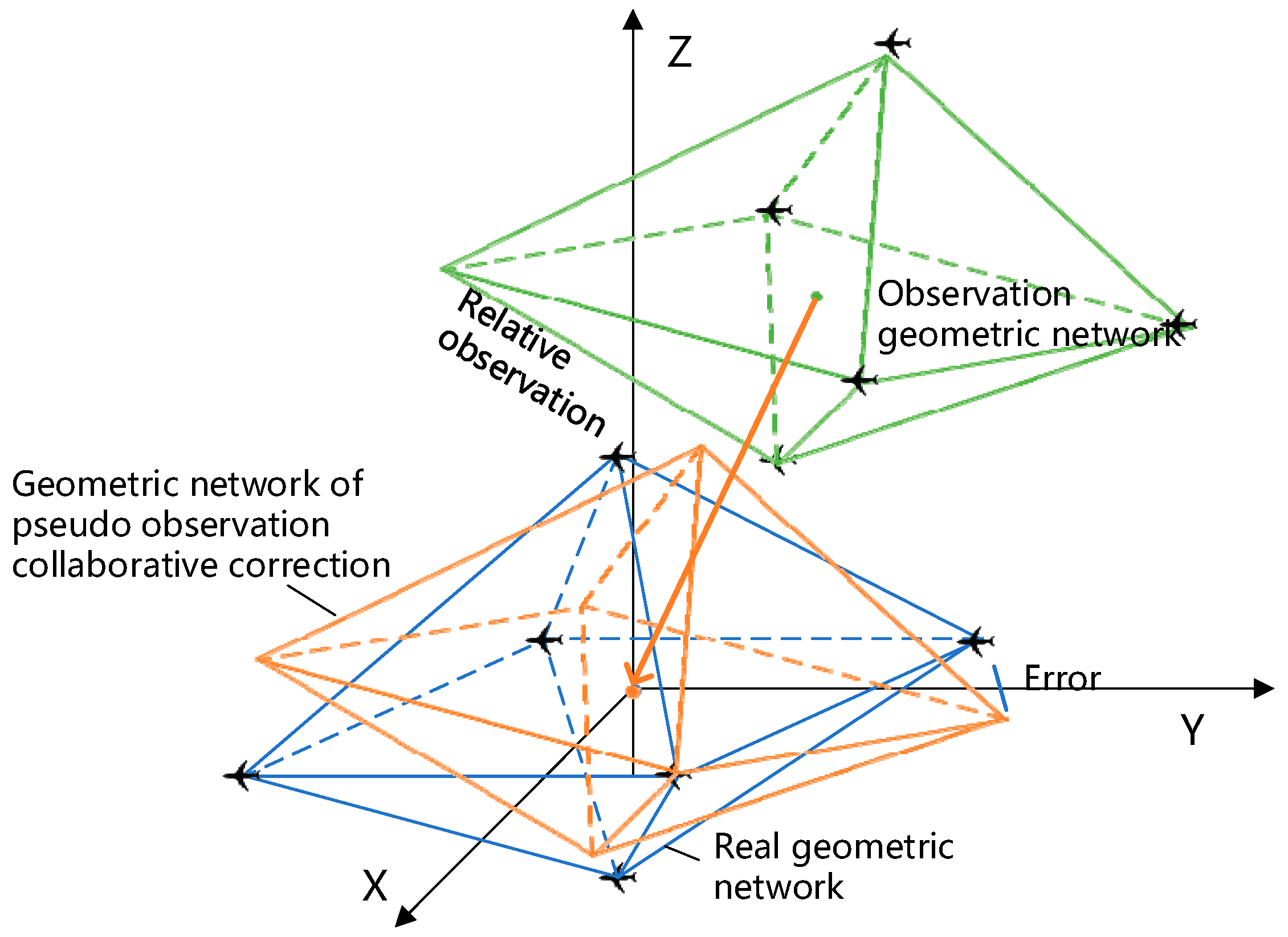
2. Construction of Hybrid Measurement Network for Aerial Swarm

2.1. Network by Relative Measurement

The cooperative observations among the aircraft can make full use of the relative observation advantages of the cluster to form a cluster observation geometric network. In some complex environments, due to the lack of external reference information and the inability of GNSS signals to cover all aircraft, the observation geometric network composed of relative observations between multi-aircraft cannot be aligned to the real position. The relationship between the observation geometric network and the real geometric network space is shown in Figure 1. At this time, the observability of positioning is obviously insufficient. With the help of the pseudo-observation method and the characteristics of the inertial navigation geometric network composed of mathematical analysis and multi-aircraft airborne inertial navigation, the observability of positioning can be improved, and therefore, the positioning accuracy of collaborative navigation can be improved. The schematic diagram of a geometric network corrected by the pseudo-observation method is shown in Figure 1.
As shown in Figure 1, the relative observation information can only determine the space relative position of multi-aircraft. To align to the real space position, three rotational degrees of freedom and three translational degrees of freedom are also required. From a mathematical point of view, there is a rank defect in the multi-aircraft cooperative observation equation.

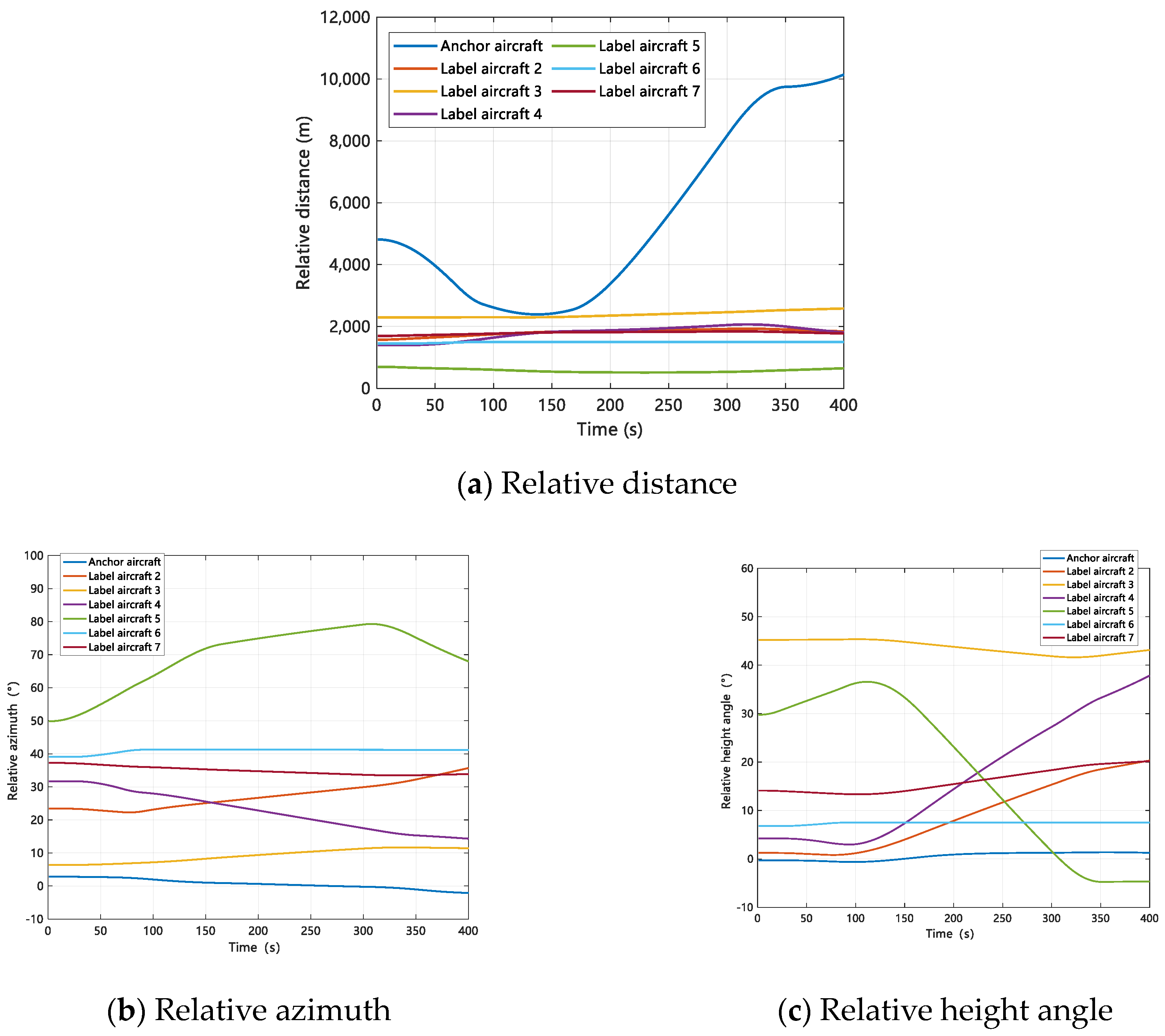
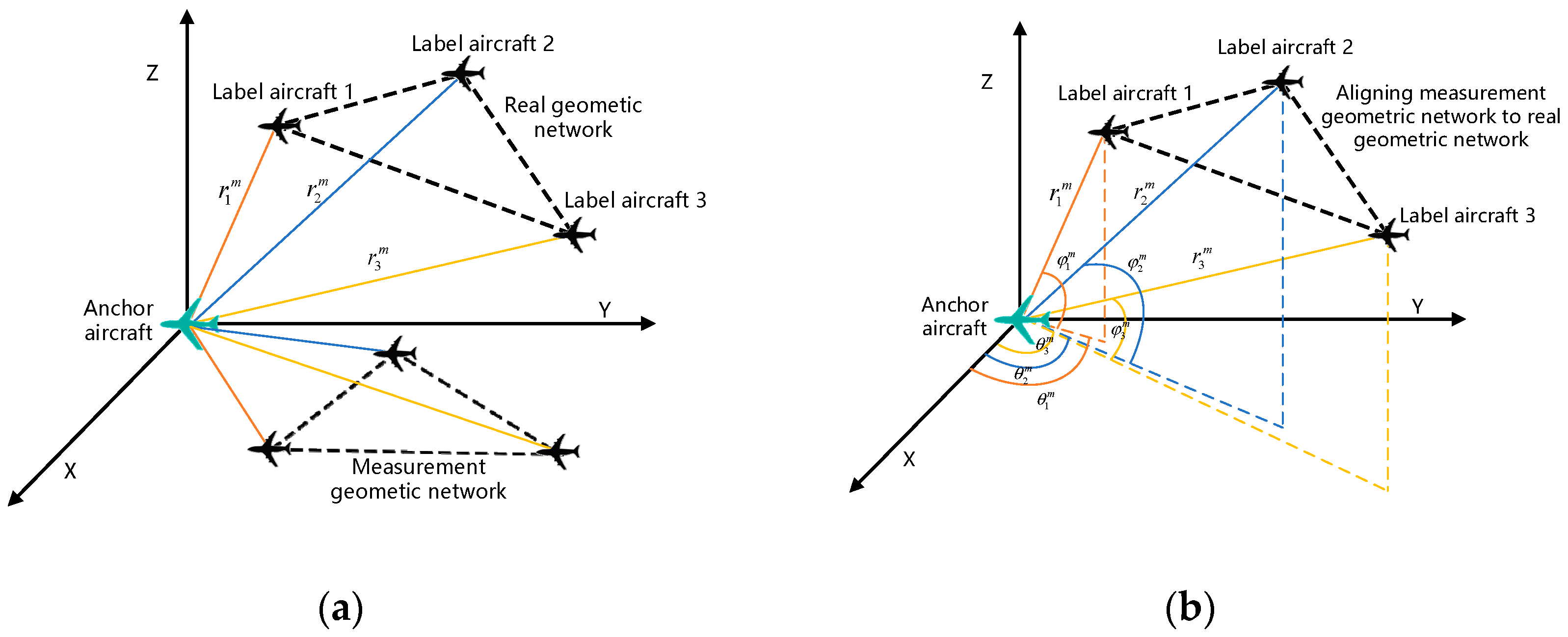
2.2. Observation Geometry with Anchors

When there is an anchor aircraft used to provide reliable information in the cluster network, the schematic diagram of space transformation based on distance observation network with anchor aircraft is as follows:
It can be seen from Figure 2a that by adding an anchor aircraft to measure the relative distance of each label aircraft, the geometric network of multi-aircraft that originally lacked the limit of six degrees of freedom increased the limit of three degrees of freedom. It reduced the observation rank defect as well as the uncertainty of cluster collaborative positioning. It can be seen from Figure 2b that by adding an anchor aircraft to measure the relative distance and the relative line-of-sight angle of each label aircraft, the multi-aircraft geometric network that originally lacked the restriction of six degrees of freedom will no longer lack the restriction of degrees of freedom. At this time, the observation of the measuring geometric network is not rank deficient. It can be seen that compared with the ranging method, the multi-aircraft geometric network of angle and ranging measurement cooperation has lower requirements on the number of anchor aircraft.

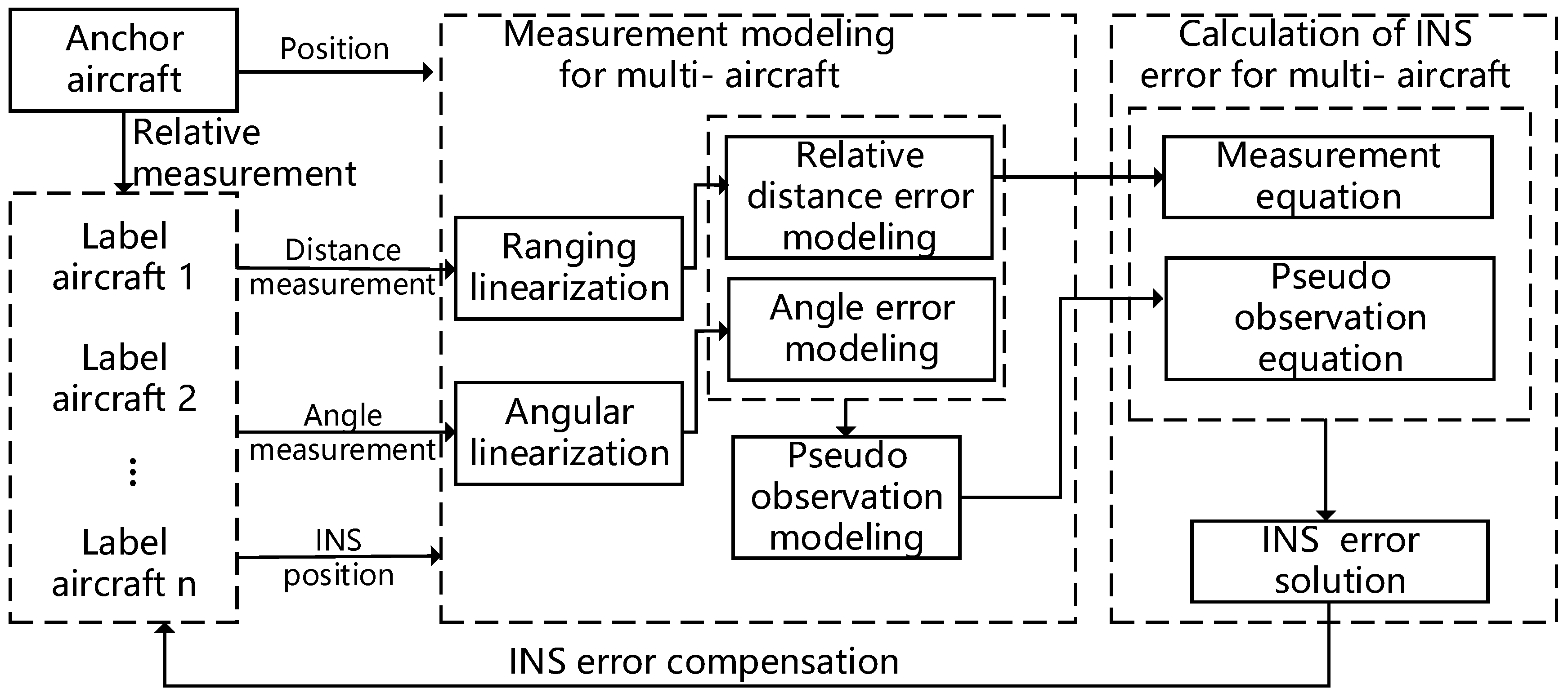
3. Collaborative Localization with Hybrid Measurement Network

3.1. Airborne Navigation Scheme with Measurement Network

In order to solve the problem of the rank defect of heterogeneous multi-aircraft cooperative observations caused by the lack of external reference information, based on the above analysis of the deviation between the multi-aircraft observation geometric network and the real geometric network, this paper designed a general scheme of heterogeneous multi-aircraft cooperative navigation error correction based on pseudo-observation, as shown in Figure 3.
As shown in Figure 3, there are two types of heterogeneous multi-aircraft: anchor aircraft and label aircraft. The anchor aircraft needs to support its high-precision positioning with the help of satellite signals. However, in the harsh environment of GNSS discussed in this paper, there are few or even no anchor aircraft in the cluster, so it is very easy to have a collaborative observation rank defect. The overall scheme of error correction based on pseudo-observation mainly includes the inter-aircraft transmission of observation and position information, the establishment of the observation model and the cooperative model, and the error calculation and correction of the airborne inertial navigation system. Firstly, each label aircraft synchronously obtains the relative observation information of other aircraft in the cluster and the output position of the airborne inertial navigation system through the cooperative measurement sensor and the aircraft communication equipment. Secondly, the heterogeneous multi-aircraft cooperative measurement modeling is carried out by using the distance and line-of-sight angle measurement information, the anchor aircraft position, and the inertial navigation position of the label aircraft. That is, the multi-aircraft inertial navigation error model based on the relative distance and the multi-aircraft inertial navigation error model based on the phase angle are established by the range linearization and the angle linearization. The pseudo-observation model is established according to the rank defect of the observation equation. Finally, the inertial navigation error of each label aircraft is obtained and the error compensation is carried out by solving the error of the cooperative observation equation fused with the pseudo-observation equation.

3.2. Modeling of Measurement Network for Aerial Swarm

Assume that the position coordinates of each label aircraft in the cluster on the geocentric earth fixed connection coordinate system are x i , y i , z i , i = 1 , 2 , , n , n is the total number of label aircraft in the cluster, and the coordinate position of the anchor aircraft is x , y , z . This paper studied the adverse combat environment of satellite signal rejection, so it was assumed that there was at most one anchor aircraft in the cluster. The inertial navigation position estimated by the airborne inertial navigation system of each label aircraft is x i I , y i I , z i I , so the estimation of its positioning error by the airborne inertial navigation system of the label aircraft can be expressed by the following formula:
δ x i , δ y i , δ z i = x i I , y i I , z i I x i , y i , z i
The measured distance between aircraft is obtained through the distance sensor, which can be expressed as:
r i j m = x i x j 2 + y i y j 2 + z i z j 2 + ε i j r
where ε i j r is the measurement noise of the distance between Aircraft i and Aircraft j .
Accordingly, the distance estimation value obtained from the inertial navigation position can be expressed as:
r i j I = x i I x j I 2 + y i I y j I 2 + z i I z j I 2
The above formula is linearized, that is, it is expanded into the Taylor series at the true value, and the first two terms are approximately taken as
r i j I x j x i 2 + y j y i 2 + z j z i 2 + x j I x i I r i j I x i x i I + y j I y i I r i j I y i y i I + z j I z i I r i j I z i z i I + x j I x i I r i j I x j x j I + y j I y i I r i j I y j y j I + z j I z i I r i j I z j z j I
Subtract Formula (4) from Formula (2) to construct the cooperative measurement equation of cluster aircraft based on distance measurement:
r i j m r i j I = x j I x i I r i j I δ x i I y j I y i I r i j I δ y i I z j I z i I r i j I δ z i I + x j I x i I r i j I δ x j I + y j I y i I r i j I δ y j I + z j I z i I r i j I δ z i I
In the same way, the distance measurement value between the aircraft and the anchor aircraft is r i m through the range sensor equipped by the aircraft, and the measurement equation based on the distance measurement between the reference and the label aircraft can be constructed:
r i m r i I = x I x i I r i j I δ x i I y I y i I r i j I δ y i I z I z i I r i j I δ z i I
Combine all n n 1 / 2 cooperative distance measurement equations and n * m relative distance measurement equations between the label aircraft and the anchor aircraft into a set of equations, expressed as:
          r i j m r i j I           r i k m r i k I           r j k m r j k I           =                                                                                                                                                                                   x i I x j I r i j I           y i I y j I r i j I         z i I z j I r i j I           x i I x j I r i j I               y i I y j I r i j I           z i I z j I r i j I                                                                                                                                                                                           x i I x k r i k I             y i I y k r i k I           z i I z k r i k I               0                             0                         0                                                                                                                                                                                                 0                                     0                               0                 x k I x j I r k j I               y k I y j I r k j I           z k I z j I r k j I                                                                                                                                                                           Δ x i I Δ y i I Δ z i I Δ x j I Δ y j I Δ z j I + ε i j r ε i k r ε j k r   Y n e t r = H n e t r X + V n e t r
where Δ x i I , Δ y i I , Δ z i I = x i I , y i I , z i I x i , y i , z i , i = 1 , 2 , , n is the inertial navigation position error of the aircraft. k = 1 , 2 , , m , m is the total number of label aircraft in the cluster, and the distance measured noise ε r obeys a normal distribution.
Based on the configuration connection of the aircraft cluster, as shown in Figure 2b, we can also obtain the corresponding azimuth angle θ i k m and height angle φ i k m . Similar to the relative distance measurement in Formula (7), we can establish a relative angle measurement equation as follows:
          θ i j I θ i j m φ i j I φ i j m           θ i k I θ i k m φ i k I φ i k m           θ j k I θ j k m φ j k I φ j k m           =                                                                                                                                                                                                                                                                             y j I y i I d i j I 2                             x j I x i I d i j I 2                       0                           y j I y i I d i j I 2                                         x j I x i I d i j I 2                                   0 x j I x i I z j I z i I d i j I r i j I 2                 y j I y i I z j I z i I d i j I r i j I 2   d i j I r i j I 2 x j I x i I z j I z i I d i j I r i j I 2         y j I y i I z j I z i I d i j I r i j I 2         d i j I r i j I 2                                                                                                                                                                                                                                                                                   y k I y i I d i k I 2                           x k I x i I d i k I 2                         0                                           0                                                       0                                   0 x k I x i I z k I z i I d i k I r i k I 2               y k I y i I z k I z i I d i k I r i k I 2     d i k I r i k I 2                           0                                                         0                                   0                                                                                                                                                                                                                                                                         0                                                     0                                           0                   y k I y j I d j k I 2                                       x k I x j I d j k I 2                               0                   0                                                     0                                           0     x k I x j I z k I z j I d j k I r j k I 2           y k I y j I z k I z j I d j k I r j k I 2         d j k I r j k I 2                                                                                                                                                                                                                                                       Δ x i I Δ y i I Δ z i I Δ x j I Δ y j I Δ z j I + ε i j θ ε i j φ ε i k θ ε i k φ ε j k θ ε j k φ                       Y n e t a = H n e t a X + V n e t a
where d i j I = x i I x j I 2 + y i I y j I 2 and the angle measured noise ε θ , ε φ obeys a normal distribution. Y n e t a = H n e t a X + V n e t a is the cooperative angle measurement equation of heterogeneous multi-aircraft including the n n 1 cooperative angle measurement equations of mutual angle measurement between the label aircraft, and the 2 n * m cooperative angle measurement equations of angle measurement between the anchor aircraft and the label aircraft.
Based on Formulas (7) and (8), the measurement model can be established as follows:
Y n e t r Y n e t a = H n e t r H n e t a X + V n e t r V n e t a Y n e t = H n e t X + V n e t           r i j m r i j I θ i j I θ i j m φ i j I φ i j m           r i k m r i k I θ i k I θ i k m φ i k I φ i k m           r j k m r j k I θ j k I θ j k m φ j k I φ j k m           =                                                                                                                                                                                                                                                         x j I x i I r i j I                                 y j I y i I r i j I           z j I z i I r i j I                       x j I x i I r i j I                                           y j I y i I r i j I                       z j I z i I r i j I                 y j I y i I d i j I 2                                 x j I x i I d i j I 2                       0                     y j I y i I d i j I 2                                         x j I x i I d i j I 2                             0   x j I x i I z j I z i I d i j I r i j I 2                   y j I y i I z j I z i I d i j I r i j I 2     d i j I r i j I 2 x j I x i I z j I z i I d i j I r i j I 2 y j I y i I z j I z i I d i j I r i j I 2     d i j I r i j I 2                                                                                                                                                                                                                                                                   x k I x i I r i k I                             y k I y i I r i k I               z k I z i I r i k I                               0                                                     0                                   0                 y k I y i I d i k I 2                             x k I x i I d i k I 2                           0                                         0                                                     0                                   0       x k I x i I z k I z i I d i k I r i k I 2               y k I y i I z k I z i I d i k I r i k I 2         d i k I r i k I 2                       0                                                     0                                   0                                                                                                                                                                                                                                                                         0                                                       0                                             0                       x k I x j I r j k I                                       y k I y j I r j k I                     z k I z j I r j k I                       0                                                       0                                             0             y k I y j I d j k I 2                                   x k I x j I d j k I 2                           0                       0                                                       0                                             0 x k I x j I z k I z j I d j k I r j k I 2     y k I y j I z k I z j I d j k I r j k I 2       d j k I r j k I 2                                                                                                                                                                                                                                                 Δ x i I Δ y i I Δ z i I Δ x j I Δ y j I Δ z j I + ε i j r ε i j θ ε i j φ ε i k r ε i k θ ε i k φ ε j k r ε j k θ ε j k φ
The auxiliary measurement of angle can reduce the requirements of the multi-aircraft geometric network on the number of anchor aircraft in the cluster. At the same time, because the observation information of the navigation system is increased, the proposed algorithm can be strengthened in terms of navigation performance.

3.3. Collaborative Localization According to Measurement Network

The cooperative observation equation of heterogeneous multi-aircraft obtained from Section 3.1 is
Y n e t = H n e t X + V n e t
where Y n e t is the cooperative observation, H n e t is the observation matrix, X is the position coordinate error estimate of each aircraft in the cluster to be solved, and V n e t is the cooperative measurement noise. Solving Formula (10) can provide the estimated value of the inertial navigation error X ^ = H n e t T P Y H n e t 1 H n e t T P Y Y n e t , where P Y is the weight matrix for measurement error.
However, the cooperative observation only cannot determine the absolute position coordinates of each aircraft in the cluster. When r a n k H n e t < r a n k X = 3 n , Formula (10) is rank deficient and H n e t T P Y H n e t is irreversible.
In order to solve the observation equation, we wanted to add a restriction matrix to make the rank defect become a non-rank defect and make the equation have a solution. That is, we constructed 0 = G T P X X + V G to make r a n k H n e t G T P X = 3 n , where we observed the full rank of the pseudo-observation equation. P X is the weight matrix of the state quantity, and V G is the pseudo-observation noise.
The pseudo-observation solution of weighted minimum norm adjustment is referred to, which gives the conditions to be satisfied for the construction of pseudo-observation equation, namely Condition 1 r a n k G = 3 n r , Condition 2 H n e t T P Y H n e t G = 0 . This paper uses the zero eigenvalue vector of H n e t T P Y H n e t to construct G . Because the zero eigenvalue vector of H n e t can just be represented by r unrelated vectors, that is, H y = 0 has basic solution systems, and the matrix G composed of the basic solution systems satisfies Condition 1 and Consition 2.
Therefore, the pseudo-observation equations are constructed using zero eigenvalues as follows:
0 = G T P X X + V G
By adding a pseudo-observation equation to make the measurement matrix full rank, a multi-aircraft cooperative observation equation incorporating the pseudo-observation equation can be constructed as follows:
Y n e t = H n e t X + V n e t 0 = G T P X X + V G
When there is no anchor aircraft in the ranging network r a n k G = 6 , adding the pseudo-observation equation can provide six spatial degrees of freedom for the cluster network, so the observation is no longer rank deficient.
At this time, the cooperative observation equation based on the pseudo-observation solution can be expressed as:
H n e t T P Y H n e t X ^ = H n e t T P Y Y n e t G T P X X ^ = 0
G T P X X ^ = 0 multiplies P X G to the left and the descendants enter H n e t T P Y H n e t X ^ = H n e t T P Y Y n e t , so the following solution formula is obtained:
X ^ = H n e t T P Y H n e t + P X G G T P X 1 H n e t T P Y Y n e t
Because P X is a positive definite weight matrix and G is composed of zero eigenvalues of H n e t T P Y H n e t , H n e t T P Y H n e t + P X G G T P X is full rank and its inverse exists, which can be solved by Formula (11) for the cooperative observation equation.
When there is no observation rank defect in the multi-aircraft geometric network, the weighted least squares method can be used to solve it. The solution formula is as follows:
X ^ = H n e t T P Y H n e t 1 H n e t T P Y Y n e t

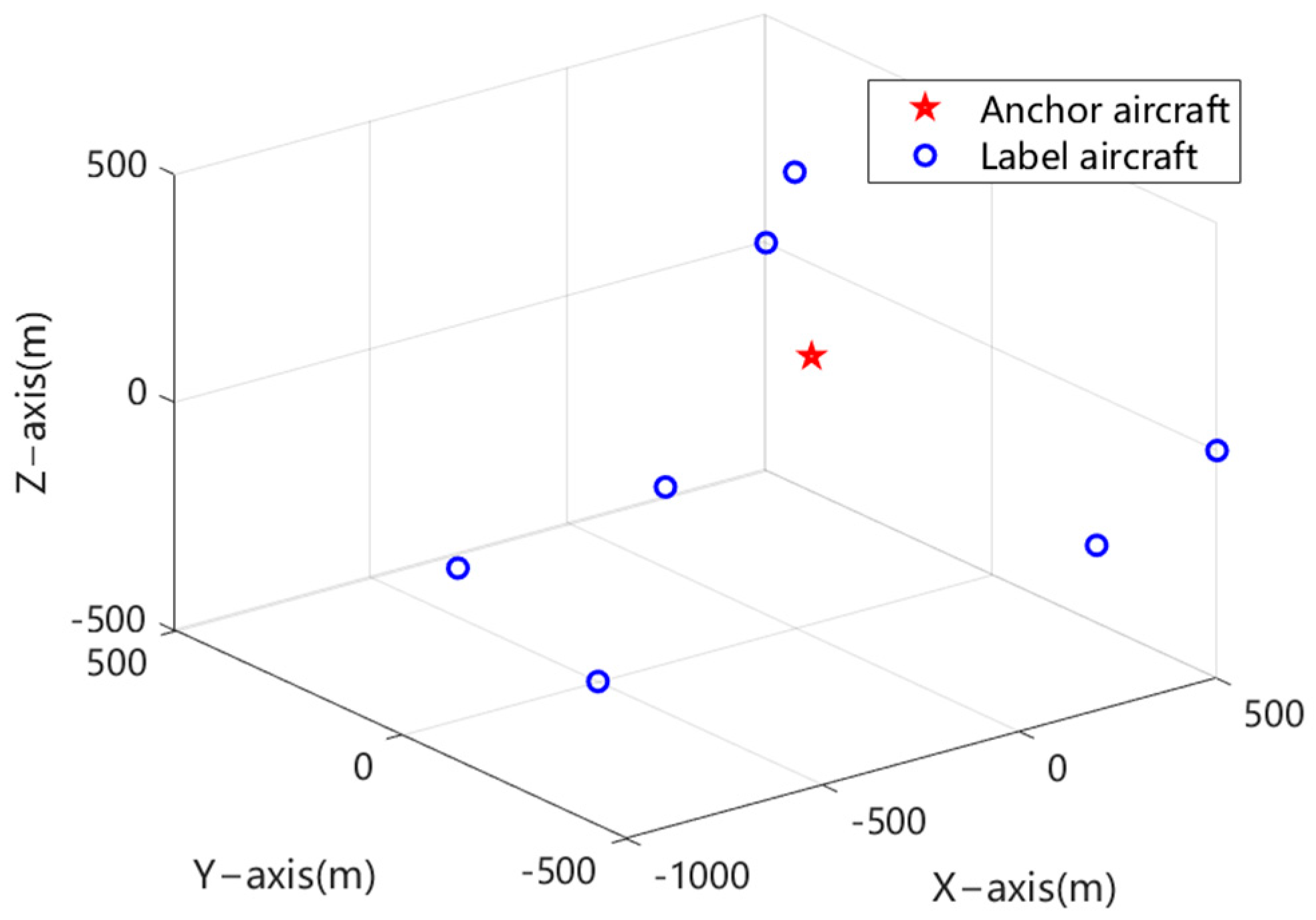
4. Simulation and Analysis

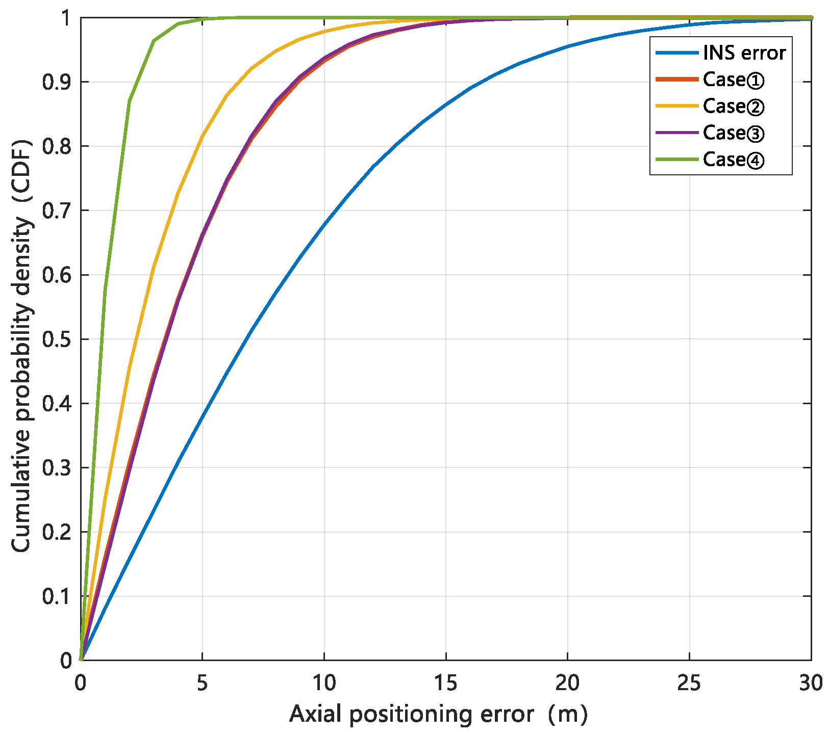
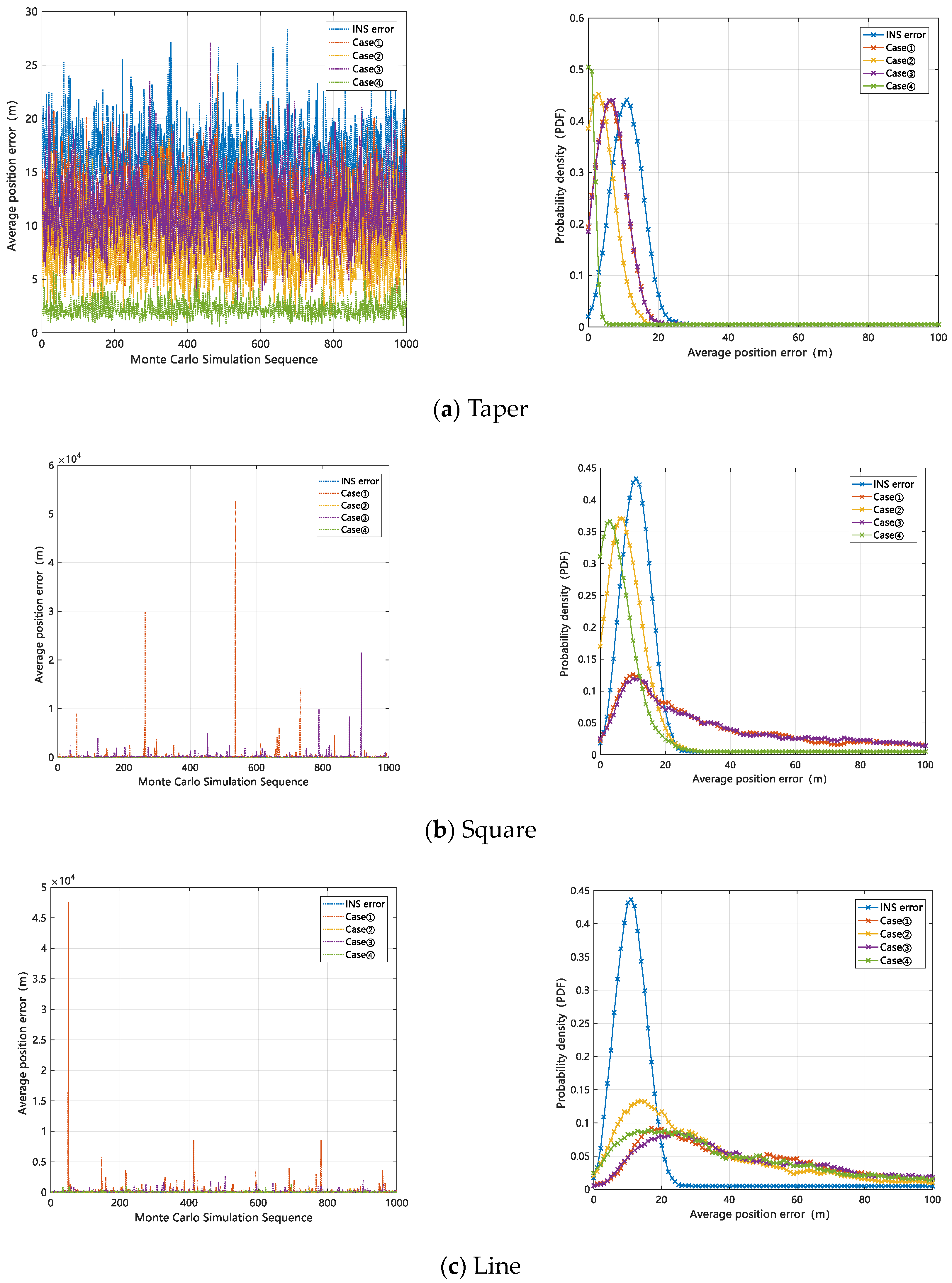
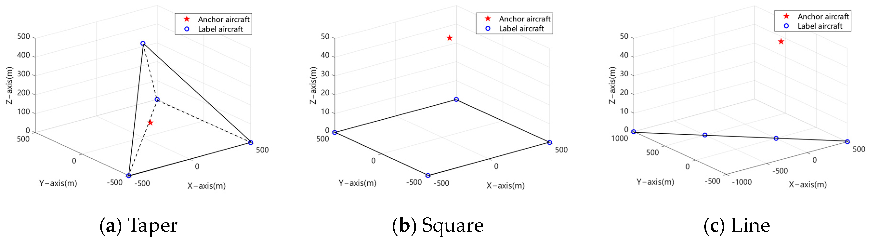
4.1. Analysis of Collaboration Mode with Hybrid Measurements

In order to verify the effectiveness of the algorithm proposed in this paper, the positioning error before and after using the algorithm was simulated and analyzed in the static positioning mode of multi-aircraft. Since the method proposed in this paper discusses the conditions of ranging cooperation, angle measurement and ranging cooperation, and whether there is an anchor aircraft cooperation, it was necessary to analyze and verify all situations during the simulation exploration in order to simplify the description. The classification of various situations is shown in Table 1.
In the static simulation, the initial error of each axis setting the inertial navigation position followed a normal distribution with a standard deviation of 10 m, the angle measurement error was 0.1°, and the ranging error was 1 m. The space position of each aircraft is shown in Figure 4, and 1000 Monte Carlo simulations were conducted.
As shown in Figure 5, the simulation statistical results of the axial positioning errors of all label aircraft are displayed in the form of CDF (cumulative distribution function) in order to analyze the algorithm performance more intuitively.
It can be seen from the inertial navigation error curve in Figure 5 that when multi-label aircraft only relied on the inertial navigation system for positioning, the cumulative probability density of the position error at 10 m was about 68%, and the cumulative probability density at 20 m was about 98%, because the initial error of each axis of the inertial navigation position followed a normal distribution with a standard deviation of 10 m. It can be seen from the case ① curve that after increasing the mutual ranging cooperation between the label aircraft, the cumulative probability density of the position error at 10 m was about 93%, and the cumulative probability density at 20 m was 100%. It can be seen from the case ③ curve that after adding the mutual ranging and angle measurement cooperation between the label aircraft, the cumulative probability density of the position error at 10 m was about 94%, and the cumulative probability density at 20 m was 100%. It can be seen from the curves of cases ② and ④ that the cumulative probability density of the position error of ranging and angular positioning in 10 m increased to 98% and 100%, respectively, by increasing the coordination of the anchor aircraft. Therefore, the co-correction method for navigation errors of heterogeneous multi-aircraft based on pseudo-observation can effectively correct the inertial navigation error, and the performance of the algorithm can be enhanced by adding the assistance of the reference vehicle. This effect is particularly significant in the cooperative mode of ranging and angle measurement.

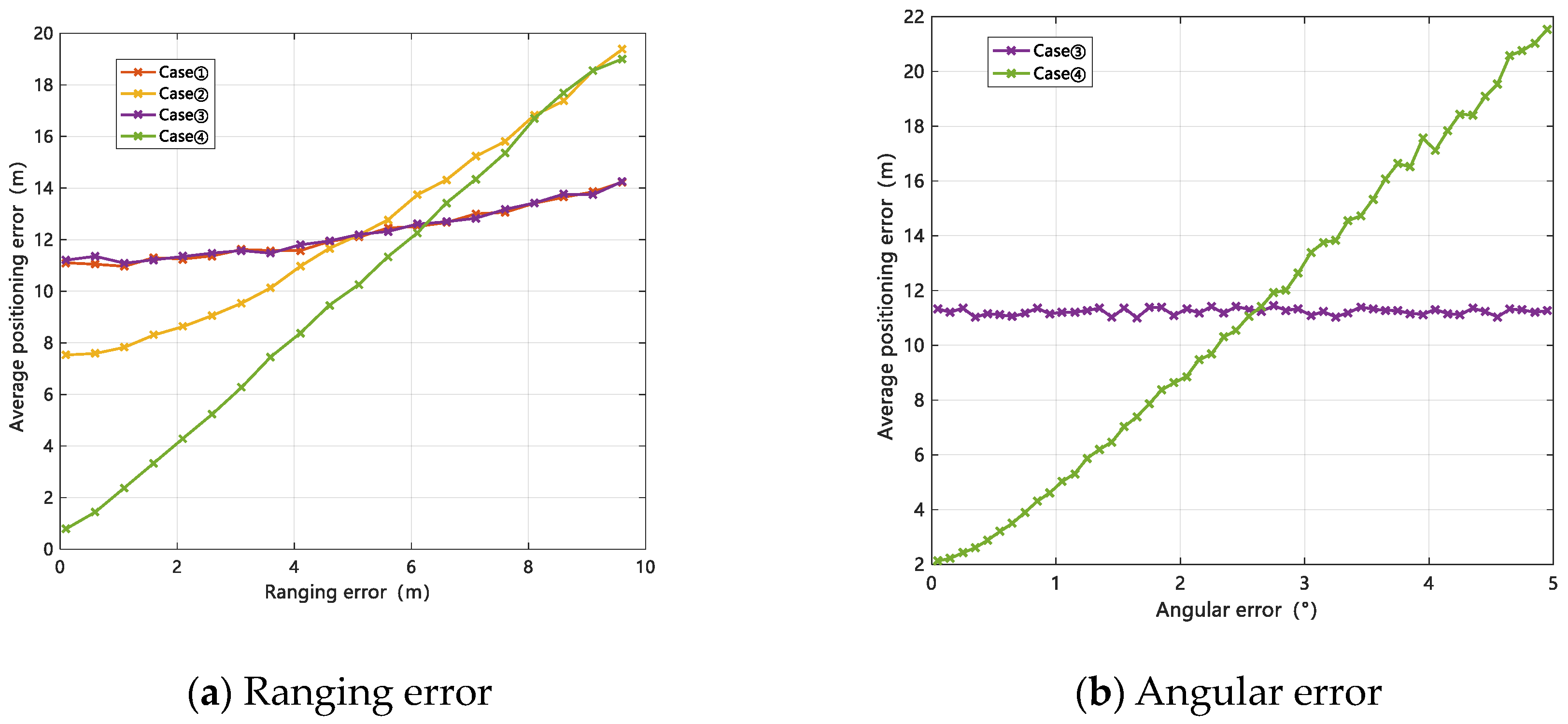
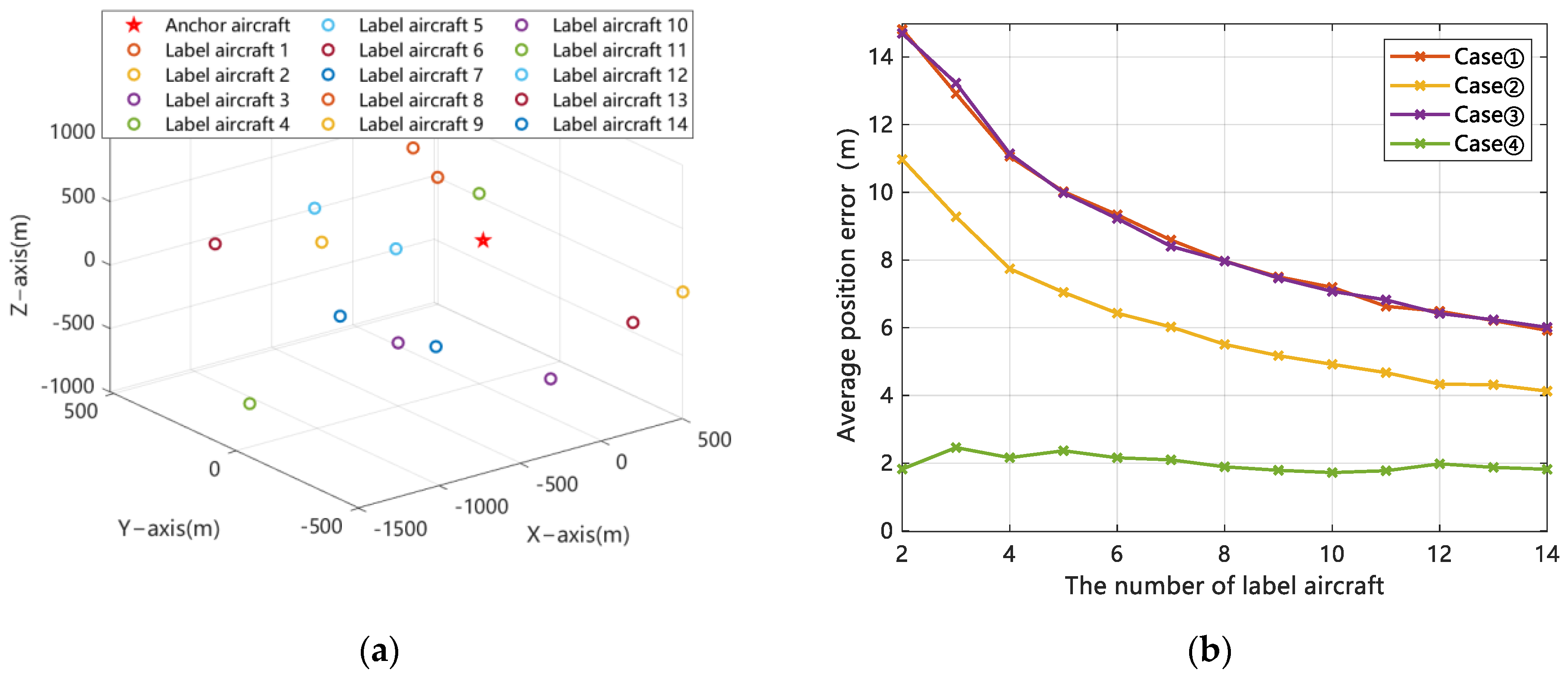
4.2. Analysis of Influential Factors on Collaborative Performance

Theoretically, the mutual observation accuracy of multi-aircraft, that is, the size of ranging and angle measurement error, the number of aircraft, and the configuration of aircraft are important factors that affect the collaborative correction method for navigation errors of heterogeneous multi-aircraft based on pseudo-observation. Therefore, this section simulated and analyzed the impact of key factors such as aircraft configuration, collaborative measurement accuracy, and the number of aircraft on the algorithm performance.
(1) Multi-aircraft configuration factor.
The collaborative correction method for navigation errors of heterogeneous multi-aircraft based on pseudo-observation proposed in this paper is closely related to the rank of the multi-aircraft cooperative observation equation. The configuration of aircraft has a great impact on the number of observation ranks, so the impact of configuration was analyzed first. The configuration of the aircraft to be simulated and analyzed was set as shown in Figure 6. The label aircraft were conical, square, and straight.
According to the situation in Table 1, the observed rank defects of each configuration in Figure 6 were classified and counted, and the statistical results are shown in Table 2.
For the conical cluster in Figure 6a, in case ①, the measurement equation was calculated to have a rank of 6 and a rank deficiency of 6. At this point, the measurement equation Y n e t = H n e t X + V n e t has no solution, and the cluster cannot perform the collaborative positioning calculation. By using the method proposed in Section 3, the eigenvector G ( r a n k G = 3 n r = 6 and r a n k H n e t G T P X = 3 n = 12 ) corresponding to the eigenvalue of H n e t T P Y H n e t was calculated to compensate for the rank deficiency of the measurement equation. Furthermore, the measurement equation was constructed as Y n e t = H n e t X + V n e t 0 = G T P X X + V G and was solvable after rank supplementation. The cluster collaborative positioning calculation was used to suppress the divergence of inertial navigation errors.
Table 2 shows that in cases ①–④, the number of observed rank defects of multi-aircraft in the square configuration and line configuration was higher than that in taper configuration. By comparing case ①, case ②, case ③, and case ④, it was found that the addition of the anchor aircraft reduced the observation rank defects of each configuration. Moreover, in the conical configuration, the addition of the anchor aircraft reduced the observation rank defect number more. Due to the increase in the rank defect number, the effectiveness of the algorithm proposed in this paper in the square and line configurations of the label aircraft will be reduced, so the navigation accuracy in the square and line configurations will be reduced.
In order to verify the above reasoning, the simulation of the average position error of multi-aircraft after using the algorithm under the above configuration was carried out, and the probability density function (PDF) of each average position error was calculated. With the exception of the configuration, the other simulation parameters were consistent with Section 4.1. The simulation results are shown in Figure 7.
It can be seen from Figure 7a that the algorithm had an obvious correction effect on the inertial navigation error under various conditions in the conical configuration, and the addition of the anchor aircraft significantly increased the probability of the average positioning error within 10 m. It can be seen from Figure 7b that in the square configuration, the magnitude of partial positioning error in case ① and case ③ was too large, and the probability of average positioning error within 10 m was significantly lower than that in the conical configuration, especially when there was no anchor aircraft coordination. It can be seen from Figure 7c that in the linear configuration, there were still some cases where the magnitude of positioning error was too large, and the probability of the average position error within 10 m in the conical configuration and the square configuration was significantly reduced, and the addition of the anchor aircraft could not be improved. Therefore, when multi-aircraft perform tasks together, the algorithm proposed in this paper should be used to correct the position error of inertial navigation, and the situation of coplanar or collinear aircraft should be avoided as much as possible.
(2) Sensor accuracy factor.
The algorithm is based on the range and angle measurement cooperation among aircraft, so the range and angle measurement accuracy will have a certain impact on the performance of the algorithm. The configuration of aircraft was maintained as shown in Figure 6a. Except for the range and angle measurement error, the other simulation conditions were consistent with the settings in Section 4.1. The variation curve of the average position error of multi-aircraft with the measurement accuracy under 1000 times of Monte Carlo simulation is shown in Figure 8.
It can be seen from Figure 8a that with the increase in ranging error, the position error of cluster aircraft also increased, and the increase in the position error was more obvious after the anchor aircraft participated in the cooperative navigation. It can be seen from Figure 8b that increasing the angle measurement error had little impact on the performance of the algorithm when the non-anchor aircraft participated in the cooperation. After increasing the anchor aircraft cooperation, the position error also increased with the increase in the angle measurement error. Therefore, the collaborative correction method for heterogeneous multi-aircraft navigation errors based on pseudo-observation proposed in this paper was restricted by sensor accuracy to a certain extent, so it was necessary to select high-precision measurement sensors within the allowable range to improve the overall navigation performance of multi-aircraft.
(3) Aircraft quantity factor.
In order to explore the impact of the number of aircraft on the algorithm performance, a simulation of the change in the average position error of multi-aircraft with the number of label aircraft was carried out. Except for the number of label aircraft and the distribution of aircraft, the other simulation conditions were consistent with the settings in Section 4.1. The distribution of aircraft is shown in Figure 9a, and the curve of the average position error of multi-aircraft with the number of label aircraft is shown in Figure 9b.
As shown in Figure 9, with the increase in the number of label aircraft, the overall average position error of multiple aircraft decreased gradually. However, in case ④ of the range and angle measurement cooperation and anchor aircraft cooperation, the average position error was not affected by the number of label aircraft and remained at a low level. Therefore, when the cluster cooperatively observes the rank defect, as in cases ①–③, appropriately increasing the number of label aircraft in the cluster within a certain range can improve the overall positioning accuracy of the cluster.

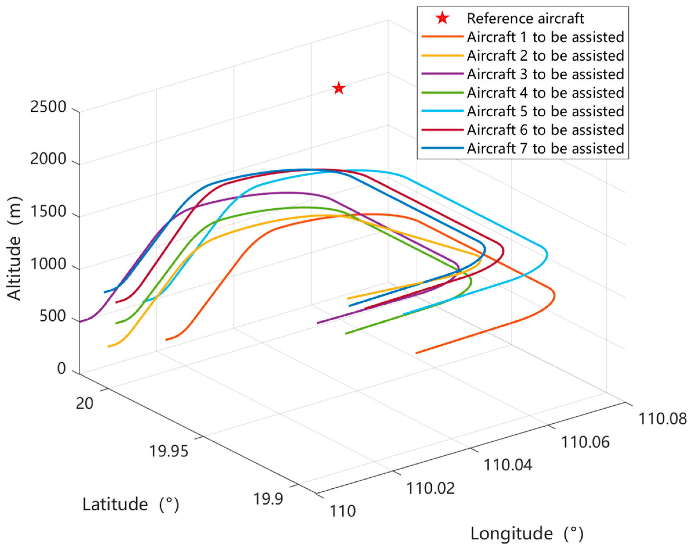
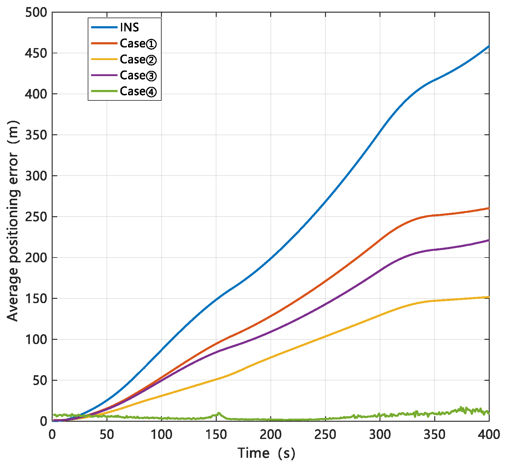
4.3. Analysis of Collaborative Navigation Performance

In order to verify the effectiveness of the algorithm proposed in this paper in the real-time navigation of heterogeneous multi-aircraft, this paper also carried out a dynamic simulation and analysis. The simulation settings of the airborne inertial sensors, ranging, and angle measurement sensors of the aircraft are shown in Table 3. The position of the anchor aircraft and the track of each label aircraft in the dynamic simulation are shown in Figure 10. The simulation time was 400 s, and the dynamic simulation was the statistical result of 20 Monte Carlo simulations.
In the dynamic simulation, the position of the anchor aircraft and the track of each label aircraft are shown in Figure 10. The cluster aircraft are divided into the anchor aircraft and the label aircraft. The anchor aircraft is located in high-altitude areas with good satellite signals, which can be approximately considered to be accurately known. The label aircraft measure each other through distance measurement sensors and angle measurement sensors, and exchange navigation information through airborne communication equipment. The anchor aircraft can provide the label aircraft with relative distance angle measurement information and its own position information. Because it was necessary to simulate and explore the cooperative correction method for navigation errors of heterogeneous multi-aircraft based on pseudo-observation under the harsh GNSS environment, at most only one anchor aircraft was considered to participate in the simulation of the algorithm. Taking label aircraft 1 as an example, the observation information changes of each aircraft relative to it in the navigation simulation are shown in Figure 11.
For the four cases described in Table 1, the average position error change curve of the seven label aircraft before and after correction using the method proposed in this paper is shown in Figure 12.
From the simulation curve, it can be seen that for the flight time of 400 s, the average position error accumulation of the label aircraft could reach more than 450 m only by relying on the inertial navigation system for navigation and positioning. After using the cooperative correction method for navigation errors of heterogeneous multi-aircraft based on pseudo-observation, the algorithm for only ranging cooperation reduced the cumulative position error to less than 300 m. On this basis, an anchor aircraft was added, and the accumulated position error was reduced to less than 150 m. It can be seen that the algorithm improved the overall positioning accuracy of the cluster by solving the observation rank defect, and the addition of the anchor aircraft further aligned the observation geometric network with the real geometric network, additionally improving the navigation accuracy. With the addition of line-of-sight angle assistance, the pseudo-observation-based coordinated correction method for navigation errors of heterogeneous multi-aircraft could also reduce the position error to less than 250 m without the addition of an anchor aircraft, which was superior to the algorithm simulation results that only relied on the range coordination method. With the addition of anchor aircraft assistance, the positioning accuracy was also greatly improved due to the fact that the observation itself was not rank defect, and the average position error was limited to 50 m. The simulation results verify the effectiveness of the co-correction method for navigation errors of heterogeneous multi-aircraft based on pseudo-observation in dynamic navigation.

5. Conclusions

Aiming at the problem of the insufficient observability of inter-aircraft cooperative measurement, this paper studied the cooperative correction method for navigation errors based on pseudo-observation. In this paper, we analyzed the observation rank defect of the heterogeneous multi-aircraft navigation and integrated the cooperative observation equation and the pseudo-observation equation between the aircraft. We also constructed a new multi-aircraft navigation model and derived the model solution method. The simulation results show that the collaborative correction method proposed in this paper can play a role in mitigating the divergence of navigation errors of multi-aircraft when the external available information is insufficient in the harsh GNSS environment. Simulation analyses of the cluster configuration, measurement accuracy, and the number of aircraft that affect the performance of the algorithm were carried out. The results show that the square configuration and line configuration of multiple aircraft reduce the performance of the algorithm, while the improvement in the measurement accuracy and the increase in the number of aircraft can enhance the effectiveness of the navigation error collaborative correction method within a certain range.

Author Contributions

Methodology, R.W.; Software, H.Z.; Validation, H.Z.; Investigation, R.W.; Data curation, C.G.; Writing—original draft, R.W. and H.Z.; Writing—review and editing, C.G.; Supervision, Z.X.; Funding acquisition, R.W. and J.L. All authors have read and agreed to the published version of the manuscript.

Funding

This work was partially supported by the National Natural Science Foundation of China (Grant Nos. 62073163, 61703208, 61873125), the “Qing Lan Project” of Jiangsu Province, the Science and Technology Innovation Project for the Selected Returned Overseas Chinese Scholars in Nanjing, the Foundation of Key Laboratory of Navigation, Guidance, and Health-Management Technologies of Advanced Aircraft (Nanjing University of Aeronautics and Astronautics), the Ministry of Industry and Information Technology, the Foundation of Engineering Research Center of Autonomous Control Technology of Aircraft (Nanjing University of Aeronautics and Astronautics), the Ministry of Education, the Jiangsu Key Laboratory “Internet of Things and Control Technologies”, and the Priority Academic Program Development of Jiangsu Higher Education Institutions.

Data Availability Statement

The data presented in this study are available in the article.

Conflicts of Interest

The authors declare no conflict of interest.

References

  1. Yang, J.; You, X.; Wu, G.; Hassan, M.M.; Almogren, A.; Guna, J. Application of reinforcement learning in UAV cluster task scheduling. Future Gener. Comput. Syst. 2019, 95, 140–148. [Google Scholar] [CrossRef]
  2. Shao, Y.; Luo, Q.; Liu, C.; Yan, X.; Yang, K. A multi-AUV cooperative navigation method. IOP Conf. Ser. Mater. Sci. Eng. 2021, 1207, 012002. [Google Scholar] [CrossRef]
  3. Kim, C.; Won, J.S. A Fuzzy Analytic Hierarchy Process and Cooperative Game Theory Combined Multiple Mobile Robot Navigation Algorithm. Sensors 2020, 20, 2827. [Google Scholar] [CrossRef] [PubMed]
  4. Causa, F.; Opromolla, R.; Fasano, G. Cooperative navigation and visual tracking with passive ranging for UAV flight in GNSS challenging environments. In Proceedings of the International Conference on Unmanned Aircraft Systems (ICUAS), Athens, Greece, 15–18 June 2021; p. 1109. [Google Scholar]
  5. Xie, P.; Kang, F.; Wang, Y. Cooperative navigation for multi-UUV using relative observations. In Proceedings of the 2010 3rd International Congress on Image and Signal Processing, Yantai, China, 16–18 October 2010; pp. 3191–3194. [Google Scholar] [CrossRef]
  6. Zhang, L.; Xu, D.; Liu, M. Cooperative Navigation Algorithm for Two Leaders GUUV. In Proceedings of the 2011 Fourth International Conference on Intelligent Computation Technology and Automation, Shenzhen, China, 28–29 March 2011; pp. 970–973. [Google Scholar] [CrossRef]
  7. Nicholson, J.W.; Healey, A.J. The present state of autonomous underwater vehicle (AUV) application and technologies. Mar. Technol. Soc. J. 2008, 42, 44–51. [Google Scholar] [CrossRef]
  8. Zhang, F.; Bao, H.; Duan, X.; Shen, J. A multiple AUVs cooperative navigation algorithm considering the effect of ocean current. In Proceedings of the 2011 International Conference on Electronics, Communications and Control (ICECC), Ningbo, China, 9–11 September 2011; pp. 2441–2445. [Google Scholar] [CrossRef]
  9. Rúa, S.; Vásquez, R.E.; Crasta, N.; Betancur, M.J.; Pascoal, A. Observability analysis for a cooperative range-based navigation system that uses a rotating single beacon. Ocean Eng. 2022, 248, 110697. [Google Scholar] [CrossRef]
  10. Feng, P. Leader-follower Cooperative Navigation with communication delays for Multi AUVs. In Proceedings of the 2011 IEEE International Conference on Signal Processing, Communications and Computing (ICSPCC), Xi’an, China, 14–16 September 2011; pp. 1–5. [Google Scholar] [CrossRef]
  11. Qi, Y.; Wang, B.; Wang, S.; Fu, M. Cooperative navigation for multiple autonomous underwater vehicles with time delayed measurements. In Proceedings of the 2016 IEEE Chinese Guidance, Navigation and Control Conference (CGNCC), Nanjing, China, 12–14 August 2016; pp. 295–299. [Google Scholar] [CrossRef]
  12. Hu, C.; Fu, L.; Yang, Y. Cooperative navigation and control for surface-underwater autonomous marine vehicles. In Proceedings of the 2017 IEEE 2nd Information Technology, Networking, Electronic and Automation Control Conference (ITNEC), Chengdu, China, 15–17 December 2017; pp. 589–592. [Google Scholar] [CrossRef]
  13. Wang, T.; Zhang, L.; Xu, D.; Feng, J. Novel cooperative navigation method for multi-AUVs based on optimal weight distribution method. In Proceedings of the OCEANS 2017, Anchorage, AK, USA, 18–21 September 2017; pp. 1–7. [Google Scholar]
  14. Fortmann, T.E.; Bar-Shalsom, Y.; Scheffe, M. Sonar tracking of multiple target using joint probabilistic data association. J. Ocean Eng. 1983, 8, 173–184. [Google Scholar] [CrossRef]
  15. Sun, X.; Xu, H.; Jiang, J. AUV cooperative navigation algorithm based on factor graph. In Proceedings of the 2019 Chinese Control And Decision Conference (CCDC), Nanchang, China, 3–5 June 2019; pp. 1053–1058. [Google Scholar] [CrossRef]
  16. Chen, Z.; Mu, H.; Chen, C.-H.; Wu, M.-P. Implement of cooperative navigation in pedestrian navigation based on distance restraint. In Proceedings of the 2016 IEEE Chinese Guidance, Navigation and Control Conference (CGNCC), Nanjing, China, 12–14 August 2016; pp. 2123–2127. [Google Scholar] [CrossRef]
  17. Liu, R.; Yuen, C.; Do, T.-N.; Jiao, D.; Liu, X.; Tan, U.-X. Cooperative relative positioning of mobile users by fusing IMU inertial and UWB ranging information. In Proceedings of the 2017 IEEE International Conference on Robotics and Automation (ICRA), Singapore, 29 May–3 June 2017; pp. 5623–5629. [Google Scholar] [CrossRef]
  18. Zhang, S.; Pan, X.; Mu, H. A multi-pedestrian cooperative navigation and positioning method based on UWB technology. In Proceedings of the 2020 IEEE International Conference on Artificial Intelligence and Information Systems (ICAIIS), Dalian, China, 20–22 March 2020; pp. 260–264. [Google Scholar] [CrossRef]
  19. Zhao, H.; Yan, Y.; Shi, X. A dynamic localization network for regional navigation under global navigation satellite system denial environments. Int. J. Distrib. Sens. Netw. 2019, 15, 15501477198. [Google Scholar] [CrossRef]
  20. Han, Y.; Wei, C.; Lu, T.; Wang, R. A Multi-platform Cooperative Localization Method Based on Dead Reckoning and Particle Filtering. In Proceedings of the 2019 Chinese Control Conference (CCC), Guangzhou, China, 27–30 July 2019; pp. 4037–4041. [Google Scholar] [CrossRef]
  21. Sun, K. A New GNSS Interference Detection Method Based on Rearranged Wavelet–Hough Transform. Sensors 2021, 21, 1714. [Google Scholar] [CrossRef] [PubMed]
  22. Zimmermann, F.; Eling, C.; Klingbeil, L.; Kuhlmann, H. Precise positioning of UAVs-dealing with challenging Rtk-GPS measurement conditions during automated UAV flights. In Proceedings of the International Conference on Unmanned Aerial Vehicles in Geomatics, Bonn, Germany, 4–7 September 2017; pp. 95–102. [Google Scholar]
  23. Liu, J.; Zhang, J.; Tan, L. A new data fusion method for multi-missile cooperative localization. In Proceedings of the IEEE 2012 Prognostics and System Health Management Conference (PHM-2012 Beijing), Beijing, China, 23–25 May 2012; pp. 1–4. [Google Scholar] [CrossRef]
  24. Liu, W.; Wu, S.; Wu, X. Relative navigation of missile formation and INS error correction methods. In Proceedings of the 2017 29th Chinese Control and Decision Conference (CCDC), Chongqing, China, 28–30 May 2017; pp. 1545–1551. [Google Scholar] [CrossRef]
  25. Causa, F.; Vetrella, A.R.; Fasano, G.; Accardo, D. Multi-UAV formation geometries for cooperative navigation in GNSS-challenging environments. In Proceedings of the 2018 IEEE/ION Position, Location and Navigation Symposium (PLANS), Monterey, CA, USA, 23–26 April 2018; pp. 775–785. [Google Scholar] [CrossRef]
  26. Wang, X.; Quan, Z.; Zhang, J.; Liu, H. Distributed collaborative navigation based on rank-defect free network. Adv. Space Res. 2022, 70, 2424–2442. [Google Scholar] [CrossRef]
  27. Wang, R.; Chen, X.; Xiong, Z.; Zhang, H.; Liu, J. A Collaborative Navigation Method based on Partnership Optimization for Clustered Aircraft. IET Radar Sonar Navig. 2022, 16, 1042–1052. [Google Scholar] [CrossRef]
Figure 1. Schematic diagram of the observation geometric network, real geometric network, and modified geometric network.
Aerospace 11 00304 g001
Figure 2. Diagram of observation rank defect of measuring geometric network. (a) Ranging observation geometric network; (b) Ranging and angular observation geometric network.
Aerospace 11 00304 g002
Figure 3. Overall scheme of the collaborative correction of navigation errors of heterogeneous multi-aircraft based on pseudo-observation.
Aerospace 11 00304 g003
Figure 4. Schematic diagram of the relative space position of static cluster aircraft.
Aerospace 11 00304 g004
Figure 5. Cumulative distribution function (CDF) of the positioning error of label aircraft.
Aerospace 11 00304 g005
Figure 6. Configuration setting of multi-aircraft.
Aerospace 11 00304 g006
Figure 7. Position error and probability density function of each configuration.
Aerospace 11 00304 g007
Figure 8. Average position error of four label aircraft with the measurement accuracy.
Aerospace 11 00304 g008
Figure 9. Distribution of aircraft and influence of the number of label aircraft. (a) Distribution of aircraft. (b) Influence of the number of label aircraft.
Aerospace 11 00304 g009
Figure 10. Schematic diagram of the track of heterogeneous multi-aircraft.
Aerospace 11 00304 g010
Figure 11. Distance and angle observations of the aircraft relative to label aircraft 1.
Aerospace 11 00304 g011
Figure 12. Change curve of average position error of the label aircraft.
Aerospace 11 00304 g012
Table 1. Collaboration mode and anchor aircraft set in the algorithm simulation analysis.
Case ①Case ②Case ③Case ④
Collaboration modeRangingRangingRanging and angularRanging and angular
Anchor aircraftNonexistentExistentNonexistentExistent
Table 2. Observed rank deficiency numbers of aircraft configurations.
Aircraft ConfigurationCase ①Case ②Case ③Case ④
Taper6360
Square7573
Line9795
Table 3. Airborne navigation sensor error parameter settings of the aircraft.
Sensor Error ParametersValue
Constant drift error of gyroscope0.3(°)/h
Gyro first-order Markov process time3600 s
Accelerometer bias error1 × 10−4 g
Accelerometer first-order Markov process time1800 s
Range sensor accuracy1 m
Angle measuring sensor accuracy0.1°
Number of label aircraft7
Disclaimer/Publisher’s Note: The statements, opinions and data contained in all publications are solely those of the individual author(s) and contributor(s) and not of MDPI and/or the editor(s). MDPI and/or the editor(s) disclaim responsibility for any injury to people or property resulting from any ideas, methods, instructions or products referred to in the content.

