
The Effect of 0–8 MPa Environmental Pressure on the Ignition and Combustion Process of CL20/NEPE Solid Propellant
Abstract
:1. Introduction
2. Experimental Research Methods and Objects
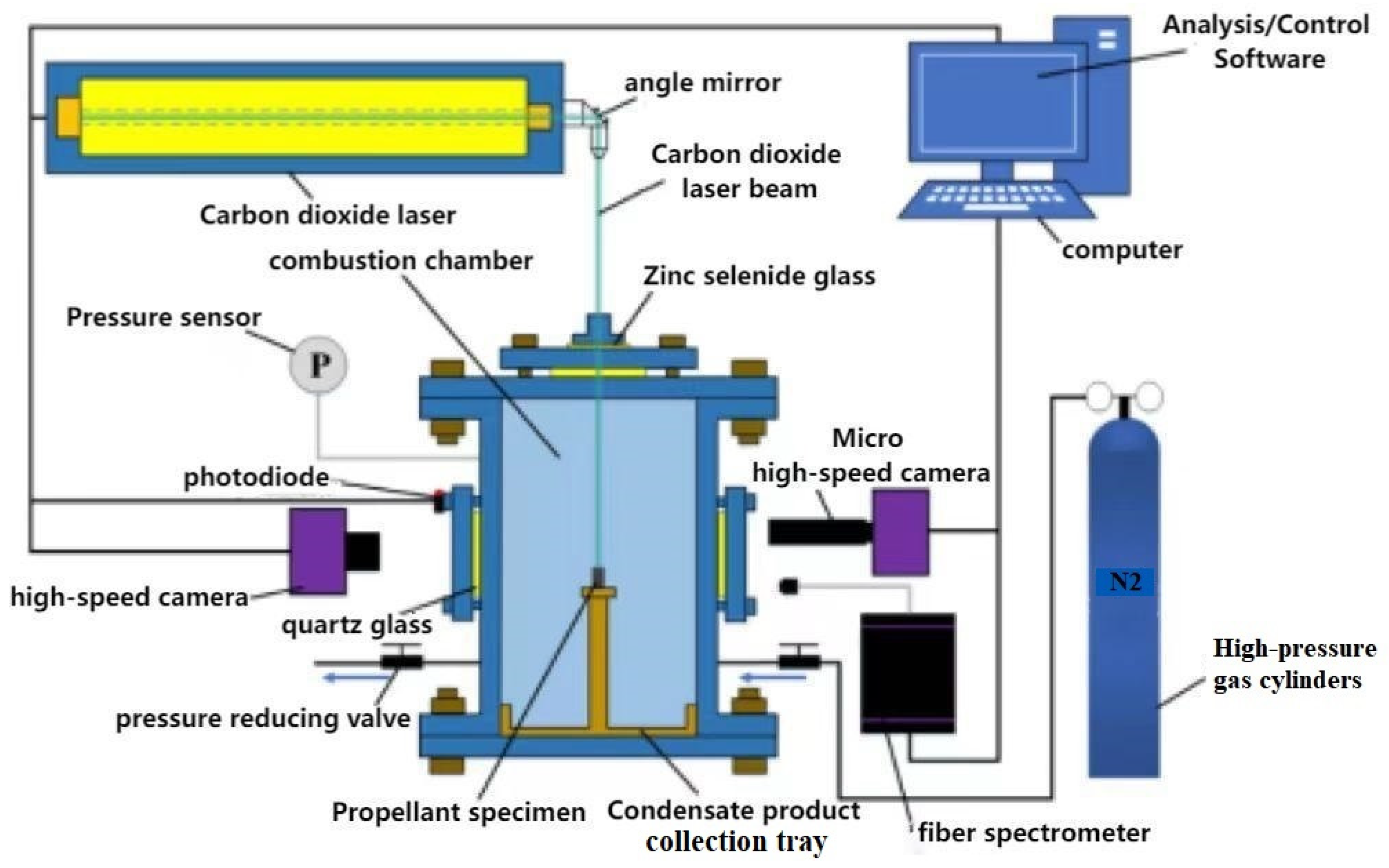
2.1. Measuring Device and Testing Methods
2.2. Research Objects and Their Physical Properties
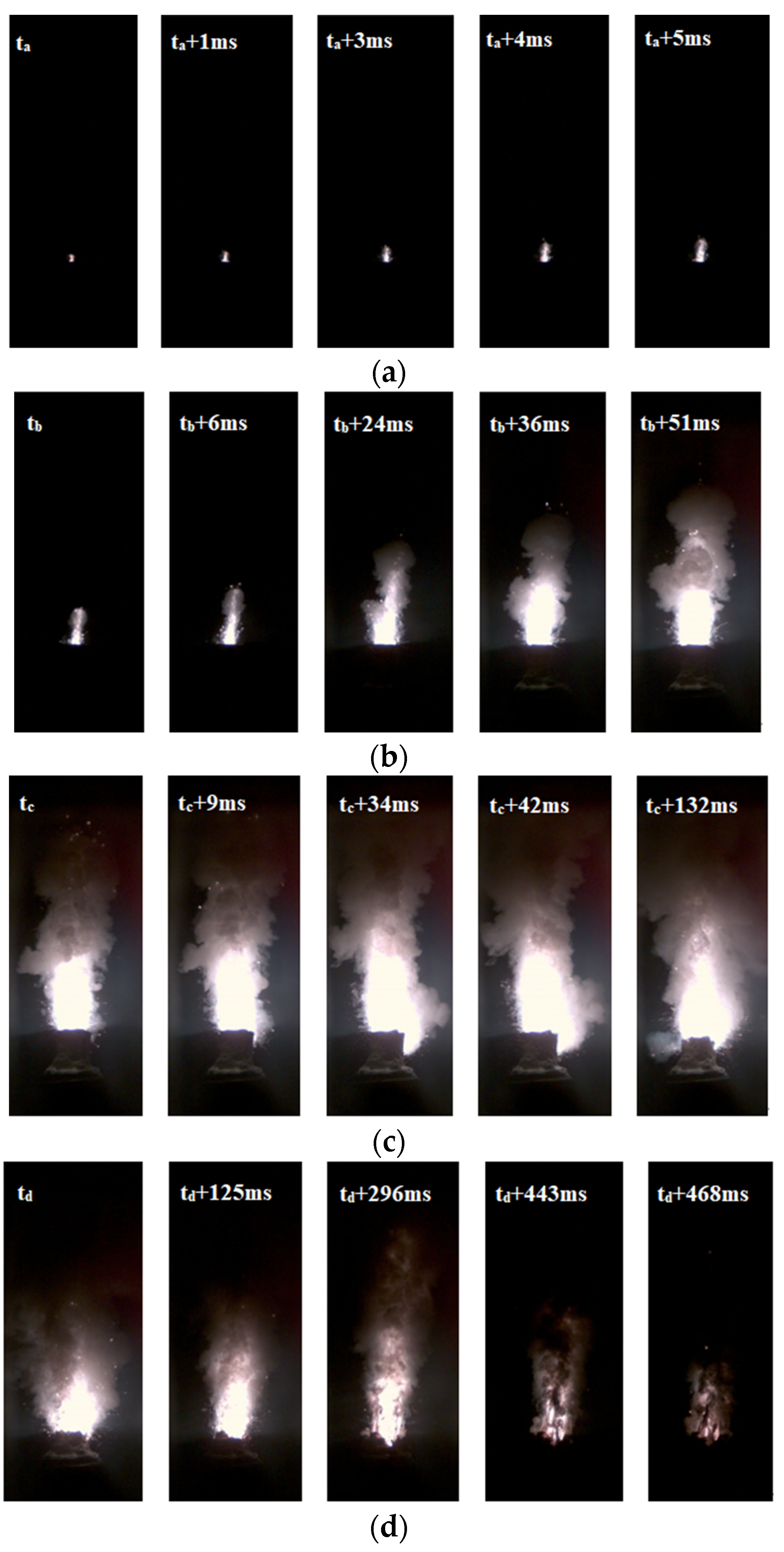
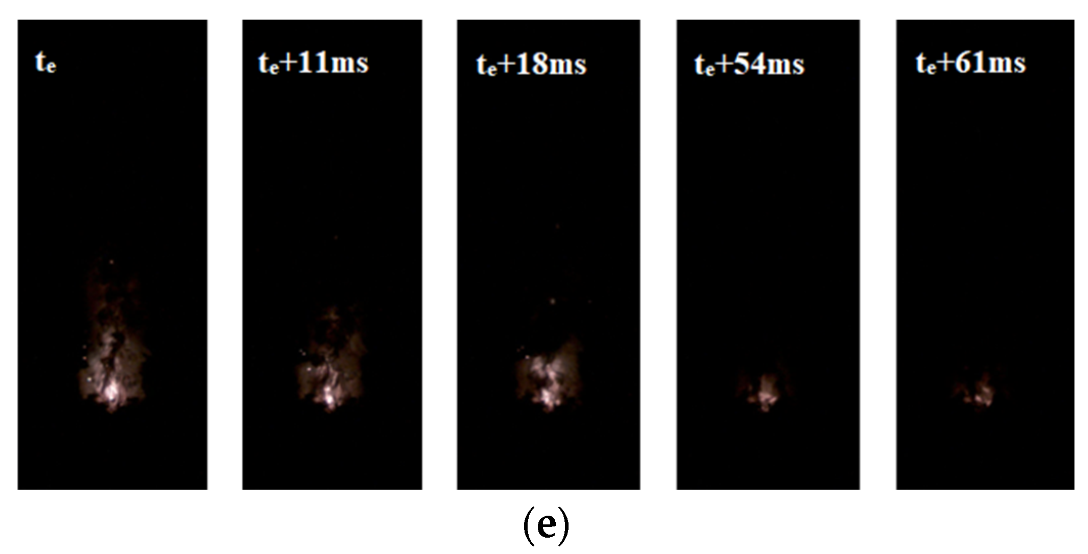
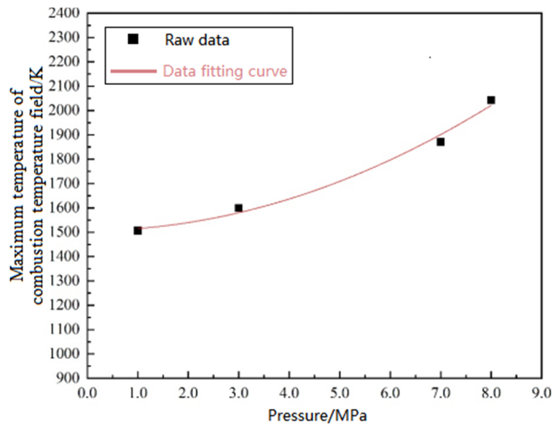
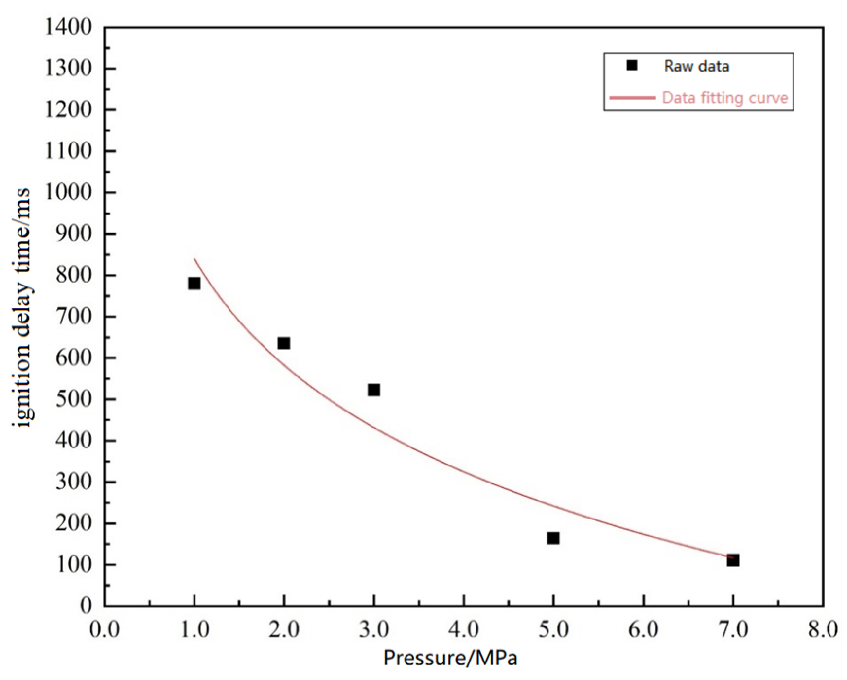
3. Influence of Environmental Pressure on Ignition and Combustion Characteristics
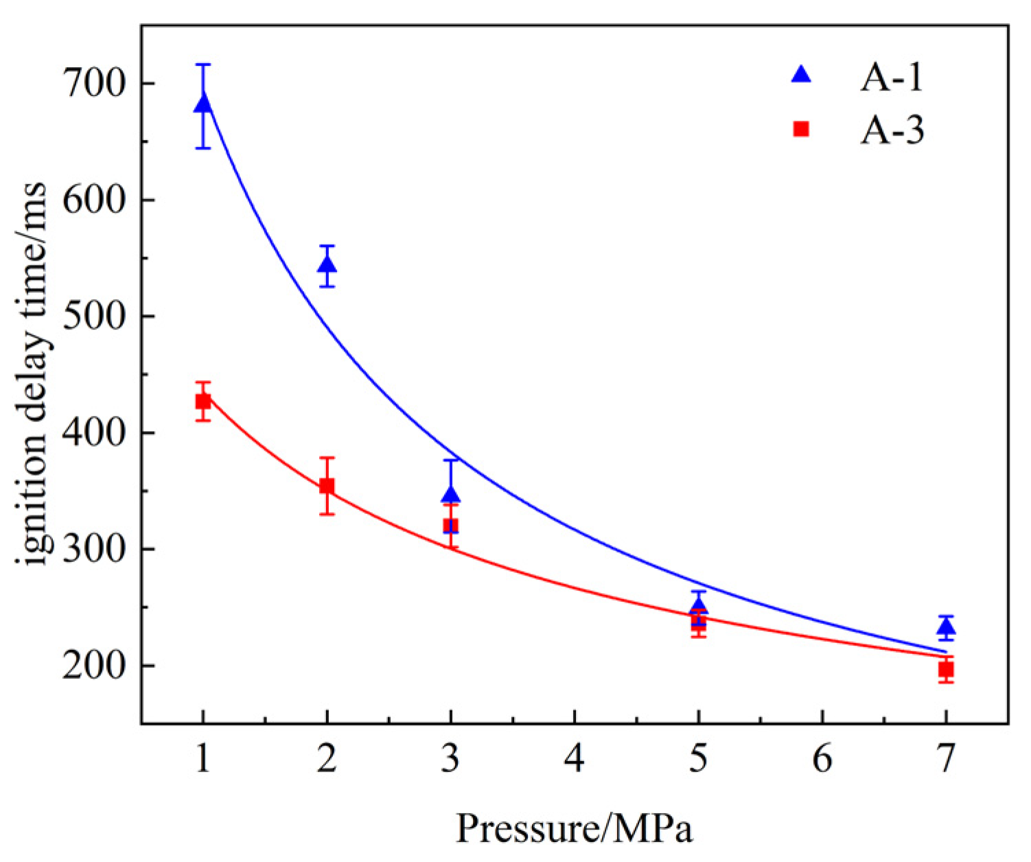
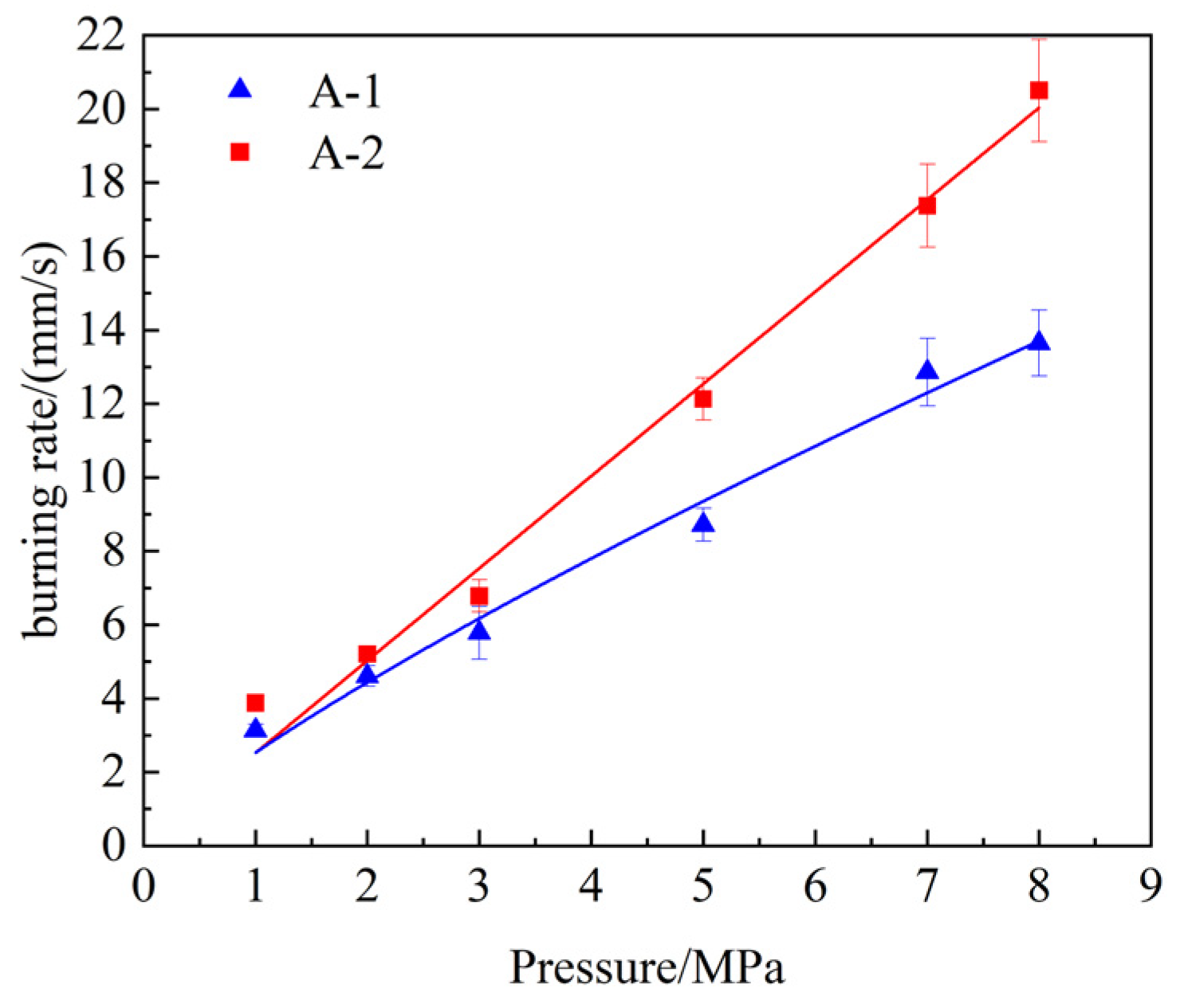
4. Influence of Propellant Components on Ignition Combustion Process
4.1. Influence of CL-20 Particle Size
4.2. Influence of Al Particle Size
4.3. Influence of AP Particle Size
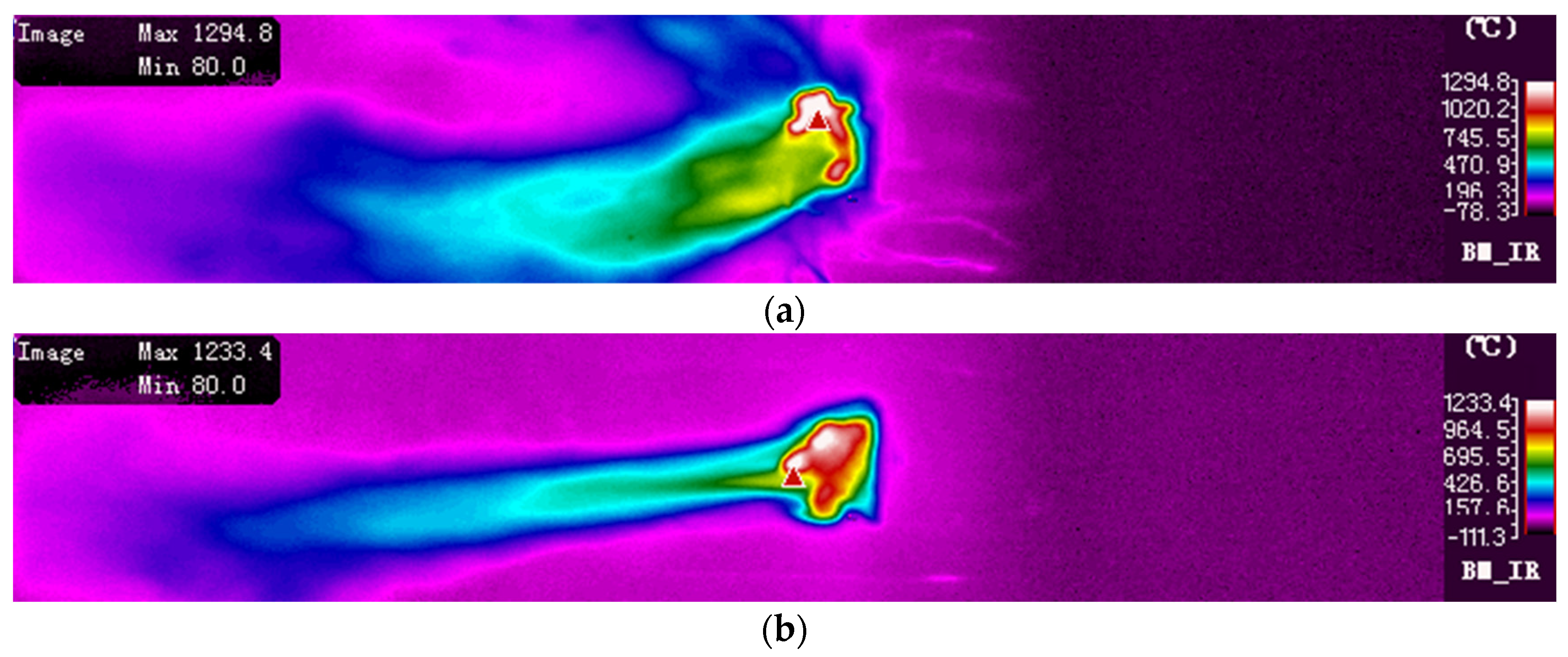
5. Research on Combustion and Agglomeration Characteristics of Aluminum Particles
5.1. Analysis of Aluminum Particle Agglomeration Process
5.2. Particle Size and Agglomeration Model of Condensate Products
6. Conclusions
- (1)
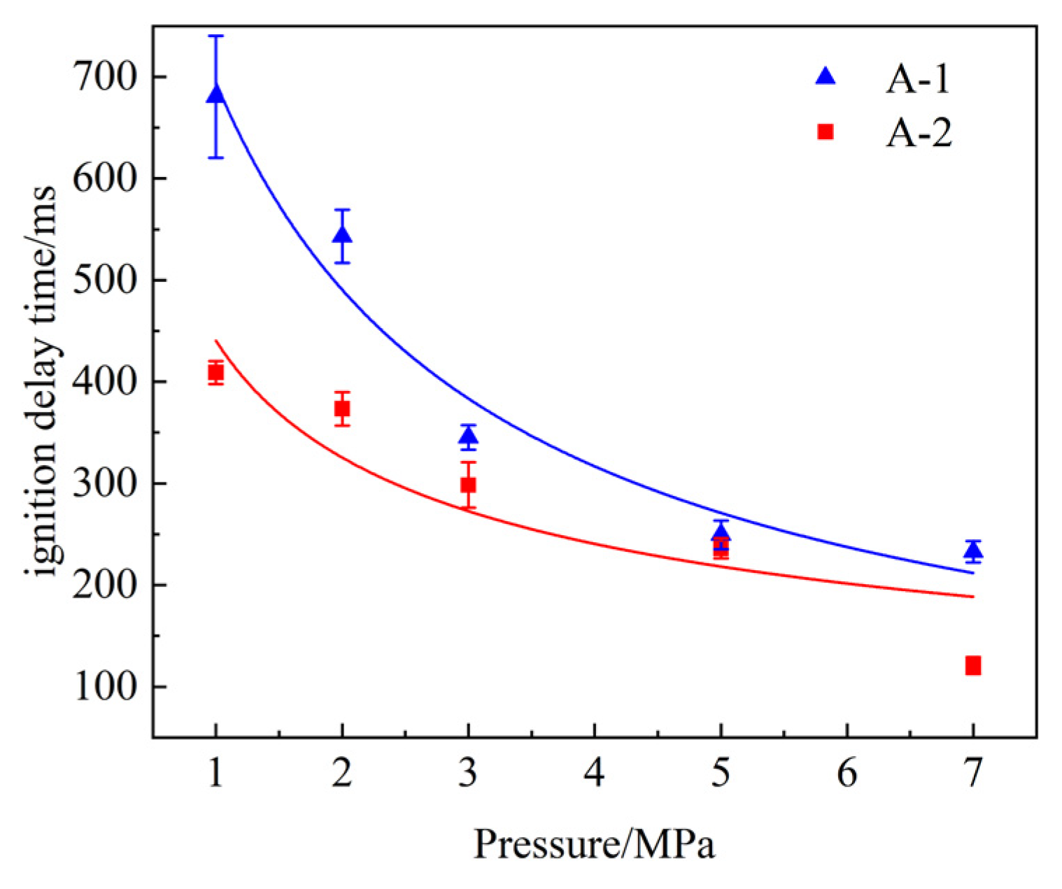
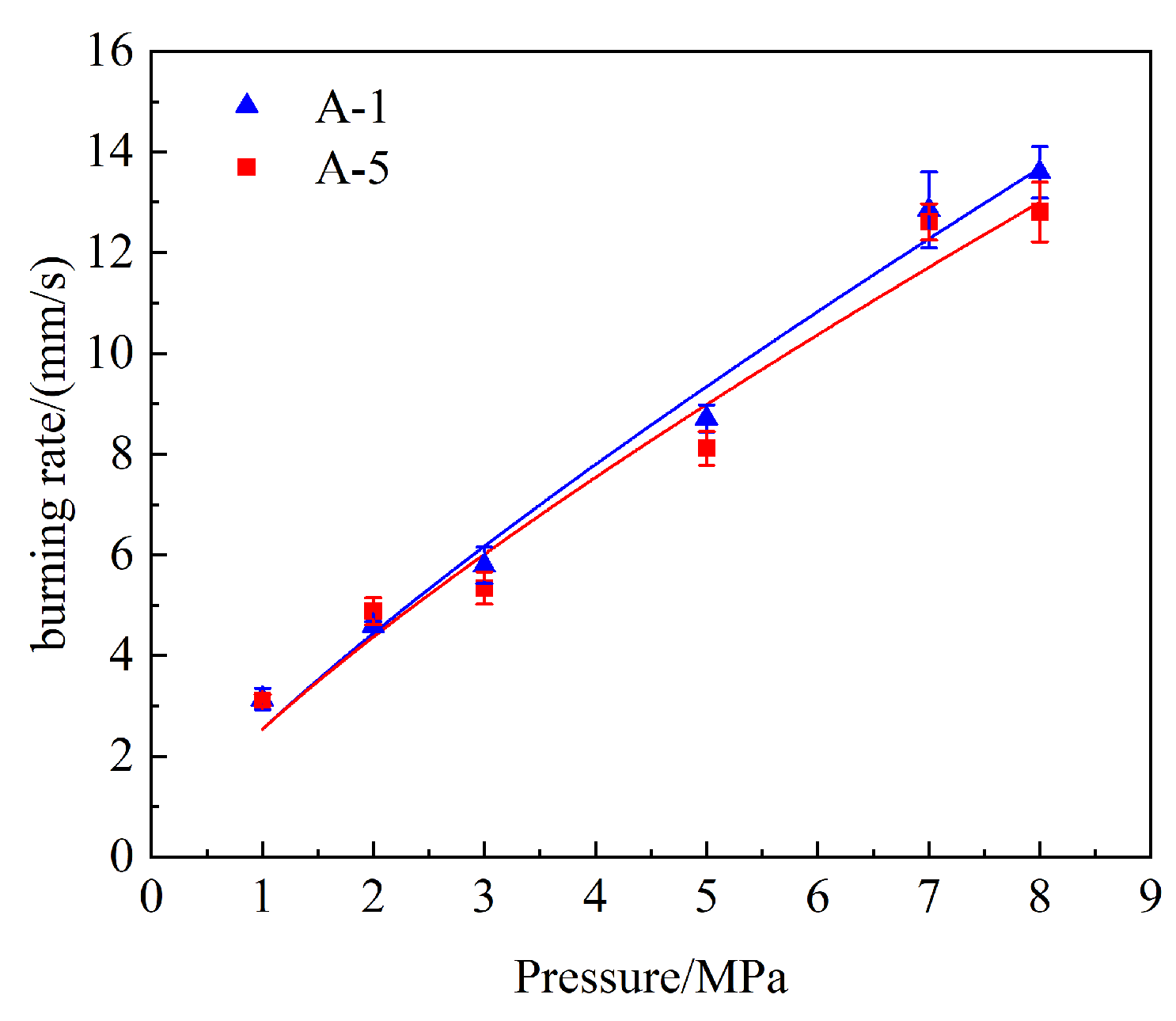
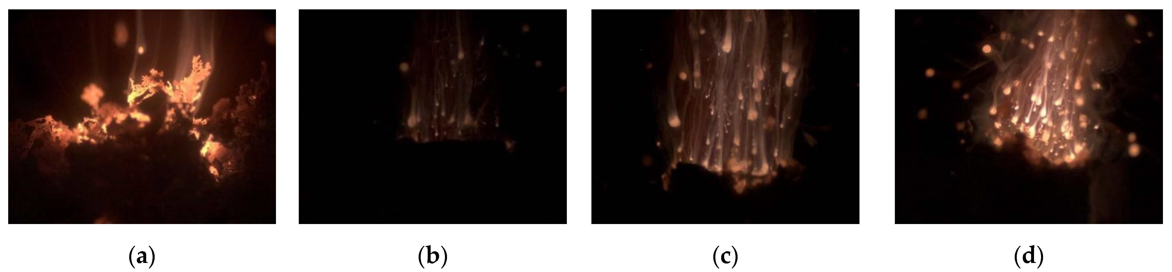
- The research results indicate that the evolution of the ignition and combustion flame process primarily consists of five stages, namely the initial ignition, combustion development, stable combustion, combustion decay, and flame quenching. Additionally, the ignition-delay times at different pressures were fitted to a function, and the results show that, as the pressure increases, the ignition-delay time decreases. Furthermore, as the pressure increases, both the burning rate and the maximum combustion temperature increase. And the effect of pressure on the ignition and combustion characteristics of the propellant diminishes. The identified patterns provide a reference for future applications of propellants;
- (2)
- The research results indicate that, as the particle size of the CL-20 in the propellant increases, it becomes more difficult for the CL-20 to be covered by the molten binder system. This results in a greater amount of pyrolysis gas being produced during the heating and decomposition process, leading to a decrease in the ignition-delay time and an increase in the burning rate. It was also found that the ignition-delay time of propellants containing coarse-grained CL-20 is less sensitive to changes in pressure. When the particle size of Al in the propellant is reduced, the interaction between Al particles and the oxidizer increases, leading to a higher heat release during the thermal decomposition reaction, stronger flame intensity, faster burning rate, and shorter ignition-delay time. When the particle size of AP in the propellant is decreased, the surface area of AP increases, promoting thermal decomposition, increasing heat feedback, and accelerating the burning rate. The study’s findings have an error margin of no more than 8%, providing significant reference points for the design of propellant formulations;
- (3)
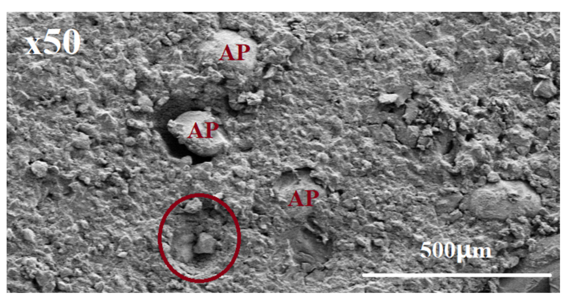
- Using optical photography techniques and a combustion-product collection system, the agglomeration phenomena and the mechanisms of the propellant were analyzed. The study shows that, as the pressure increases, the duration of the coral-like morphology in the aluminum particle agglomeration process significantly decreases. And the number of aluminum particles escaping from the propellant combustion surface increases. By combining the various agglomeration behaviors of aluminum particles observed in the experiments, a physical model was established to comprehensively understand the formation process and principles of aluminum agglomerates. Based on the principles of the classical pocket model, a mathematical model was proposed to predict the size of agglomerates, and when comparing the experimental results with the predicted results, it was found that the predictive model had a high degree of agreement with the experimental data.
Author Contributions
Funding
Data Availability Statement
Conflicts of Interest
References
- Wu, X.; Chen, J.; Wang, D. Principles of Solid Rocket Motor; Arms Industry Press: Beijing, China, 2011. [Google Scholar]
- Gnanaprakash, K.; Chakravarthy, S.R.; Sarathi, R. Combustion mechanism of composite solid propellant sandwiches containing nano-aluminium. Combust. Flame 2017, 182, 64–75. [Google Scholar] [CrossRef]
- Li, L.B.; Chen, X.; Musa, O.; Zhou, C.S.; Zhu, M. The effect of pressure and oxygen concentration on the ignition and combustion of aluminum-magnesium fuel-rich propellant. Aerosp. Sci. Technol. 2018, 76, 394–401. [Google Scholar] [CrossRef]
- Guo, Y.; Li, J.; Gong, L.; Xiao, F.; Yang, R.; Meng, L. Effect of Aluminum and Organic Fluoride on the Combustion Properties of Hydroxyl Terminated Polybutadiene Propellant. Chin. J. Explos. Propellants 2020, 43, 74–80. [Google Scholar]
- Takahashi, K.; Oide, S.; Kuwahara, T. Agglomeration characteristics of aluminum particles in AP/AN composite propellants. Propellants Explos. Pyrotech. 2013, 38, 555–562. [Google Scholar] [CrossRef]
- Liu, X.; Liu, P.J.; Jin, B. Experimental Study Methods for Combustion of Aluminum in Composite Propellants. Solid Rocket Technol. 2015, 38, 833–836. [Google Scholar]
- Liu, X.; Liu, P.J.; Jin, B. Experimental Study on Aluminum Combustion in Composite Propellants. J. Propuls. Technol. 2016, 37, 1579–1585. [Google Scholar]
- Liu, X.; Ao, W.; Liu, H.; Liu, P. Aluminum agglomeration on burning surface of NEPE propellants at 3–5 MPa. Propellants Explos. Pyrotech. 2016, 42, 260–268. [Google Scholar] [CrossRef]
- Ao, W.; Liu, X.; Rezaiguia, H.; Liu, H.; Wang, Z.; Liu, P. Aluminum agglomeration involving the second mergence of agglomerates on the solid propellants burning surface: Experiments and modeling. Acta Astronaut. 2017, 136, 219–229. [Google Scholar] [CrossRef]
- Li, L.; Chen, X.; Zhou, C.; Zhu, M.; Lai, J. Characteristics of Aluminium Particle Agglomeration in Aluminum-magnesium Oxygen-depleted Propellants. Chin. J. Energetic Mater. 2019, 27, 759–765. [Google Scholar]
- Yuan, J.; Liu, J.; Zhou, Y.; Wang, J.; Xv, T. Aluminum agglomeration of AP/HTPB composite propellant. Acta Astronaut. 2019, 156, 14–22. [Google Scholar] [CrossRef]
- Tu, C.Y.; Chen, X.; Li, Y.K.; Zhang, B.C.; Zhou, C.S. Experimental study of Al agglomeration on solid propellant burning surface and condensed combustion products. Def. Technol. 2022, 5, 2214–9147. [Google Scholar] [CrossRef]
- Tu, C.; Zhuang, Y.; Li, Y.; Zhou, C.; Cai, W.; Chen, X.; Li, W. Combustion Process and Aluminum Agglomeration Characteristics of NEPE Propellant. J. Aerosp. Power 2022, 10, 1–8. [Google Scholar]
- Tu, C.; Lin, Z.; Dong, L.; Zhuang, Y.; Li, Y.; Zhou, C.; Cai, W.; Chen, X. Dynamic Behavior Study of Aluminum Aggregates on NEPE Propellant Combustion Surface. J. Propuls. Technol. 2022, 11, 1–10. [Google Scholar]
- Liu, Z.; Li, S.; Liu, M.; Guan, D.; Sui, X.; Wang, N. Experimental investigation of the combustion products in an aluminised solid propellant. Acta Astronaut. 2017, 133, 136–144. [Google Scholar] [CrossRef]
- Zhou, X.; Zou, M.; Huang, F.; Yang, R.; Guo, X. Effect of organic fluoride on combustion agglomerates of aluminized HTPB solid propellant. Propellants Explos. Pyrotech. 2017, 42, 417–422. [Google Scholar] [CrossRef]
- Gallier, S. A stochastic pocket model for aluminum agglomeration in solid propellants. Propellants Explos. Pyrotech. 2009, 34, 97–105. [Google Scholar] [CrossRef]
- Gnanaprakash, K.; Chakravarthy, S.R. Effect of binder melt flow on the leading edge flames of solid propellant sandwiches. Proc. Combust. Inst. 2019, 37, 3127–3134. [Google Scholar] [CrossRef]
- Chen, Y.; Zhu, B.; Sun, Y.; Zhang, S.; Shi, W.; Liu, X. Effects of ammonium perchlorate particle size on the aluminum agglomeration in primary combustion of the ammonium perchlorate/ aluminum binary mixture with a high aluminum content. Energy Fuels 2019, 33, 9302–9308. [Google Scholar] [CrossRef]
- Li, L. Experimental and Numerical Study of Combustion and Particle Agglomeration Characteristics of Solid-Fueled Ram Engines; Nanjing Unversity of Science and Technology: Naniing, China, 2019. [Google Scholar]
- Grigor’Ev, V.G.; Kutsenogii, K.P.; Zarko, V.E. Model of aluminum agglomeration during the combustion of a composite propellant. Combust. Explos. Shock Waves 1981, 17, 356–363. [Google Scholar] [CrossRef]
- Li, L.B.; Chen, X.; Zhou, C.S.; Li, W.X.; Zhu, M. Experimental and model investigation on agglomeration of aluminized fuel-rich propellant in solid fuel ramjet. Combust. Flame 2020, 219, 437–448. [Google Scholar] [CrossRef]
- Duterque, J.; Propulsion, C. Experimental studies of aluminum agglomeration in solid rocket motors. Int. J. Energetic Mater. Chem. Propuls. 1997, 4, 693–705. [Google Scholar] [CrossRef]


| Instrument | Model | Parameter |
|---|---|---|
| High-speed camera | Chronos 1.4 | resolving power 1280 × 1024@1000 FPS |
| Telephoto microscope lens | XDC-10A | Working distance 95 mm |
| Fiber spectrometer | AvaSpec-ULS4096CL-EVO | Wavelength range 200–1100 nm; Resolution 0.05–20 nm |
| Infrared thermal imager | FLIR A615 | Temperature range +300 to +2000 °C; 200 FPS frame rate, transmitting 16-sbit images |
| Measuring Equipment | Model | Parameter |
|---|---|---|
| Scanning electron microscope and X-ray spectroscopy combined equipment | Hitachi HITACHI SU3500 | SEM magnification 5–300 k |
| laser particle size analyzer | Mastersize 3000 | Particle size range: 0.01–3500 μm |
| TGA | TGA/SDTA851E | Heating at a rate of 10 °C/min |
| X-ray diffractometer | D8 Advance | Angle reproducibility ± 0.0001° |
| Sample Code | Illustrate |
|---|---|
| A-1 | Basic formula (Al particle size 3 μm. AP particle size 250 μm. CL-20 & HMX particle size 250 μm) |
| A-2 | Al particle size 30 μm |
| A-3 | CL-20 & HMX particle size 100 μm |
| A-4 | AP particle size 350 μm |
| A-5 | AP particle size 450 μm |
| A-8 | Plasticization ratio 2.1 |
| A-9 | Plasticization ratio 2.9 |
| Parameter | Numerical Value |
|---|---|
| ρAP | 1.95 × 10³ kg/m3 |
| ρAl | 2.7 × 10³ kg/m3 |
| ρP | 1.64 × 10³ kg/m3 |
| ρAl,l ρCL-20 | 2.35 × 10³ kg/m3 2.04 × 10³ kg/m3 |
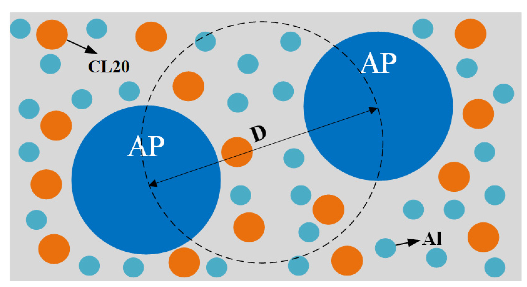
| D | 280 μm |
Disclaimer/Publisher’s Note: The statements, opinions and data contained in all publications are solely those of the individual author(s) and contributor(s) and not of MDPI and/or the editor(s). MDPI and/or the editor(s) disclaim responsibility for any injury to people or property resulting from any ideas, methods, instructions or products referred to in the content. |
© 2024 by the authors. Licensee MDPI, Basel, Switzerland. This article is an open access article distributed under the terms and conditions of the Creative Commons Attribution (CC BY) license (https://creativecommons.org/licenses/by/4.0/).
Share and Cite
Cai, W.; Li, W.; Wang, Z. The Effect of 0–8 MPa Environmental Pressure on the Ignition and Combustion Process of CL20/NEPE Solid Propellant. Aerospace 2024, 11, 672. https://doi.org/10.3390/aerospace11080672
Cai W, Li W, Wang Z. The Effect of 0–8 MPa Environmental Pressure on the Ignition and Combustion Process of CL20/NEPE Solid Propellant. Aerospace. 2024; 11(8):672. https://doi.org/10.3390/aerospace11080672
Chicago/Turabian StyleCai, Wenxiang, Wei Li, and Zhixiang Wang. 2024. "The Effect of 0–8 MPa Environmental Pressure on the Ignition and Combustion Process of CL20/NEPE Solid Propellant" Aerospace 11, no. 8: 672. https://doi.org/10.3390/aerospace11080672