Article

The Aerodynamic Performance of a Novel Overlapping Octocopter in Hover

School of Mechanical Engineering and Automation, Fuzhou University, Fuzhou 350116, China
*
Author to whom correspondence should be addressed.
Aerospace 2024, 11(9), 737; https://doi.org/10.3390/aerospace11090737
Submission received: 10 July 2024 / Revised: 27 August 2024 / Accepted: 4 September 2024 / Published: 9 September 2024
(This article belongs to the Special Issue Aerodynamic Numerical Optimization in UAV Design)

Abstract

:
A novel octocopter with an overlapping rotor arrangement is proposed in this paper to increase the payload with a limited size. The aerodynamic performance was obtained by both experiments and numerical simulations with the rotor spacing ranging from 1.2 D to 2.0 D ( L = 1.2   D ,   1.4   D ,   1.6   D ,   1.8   D ,   2.0   D ). Also, the aerodynamic parameter was evaluated by the thrust, power consumption, thrust coefficient, power coefficient, and figure of merit (FM) in hover. Compared with a traditional co-axial octocopter, the results indicated that the overlapping octocopter at L = 1.8   D presented an increasing thrust up to 15.98%, and the FM increment was up to 6%. Additionally, the streamline distribution showed that the symmetry of the vortex movement in the downwash flow for the overlapping rotors will offset the rotor interference with an increase in thrust. Meanwhile, the vortex deformation resulting from the induced velocity from the upper rotor also led to an increase in power consumption. Finally, the optimal aerodynamic performance of the overlapping octocopter was obtained with a rotor spacing of L = 1.8   D at 1800 RPM.

1. Introduction

Micro aerial vehicles (MAVs) are widely used in aerial photography, natural disaster rescue, battlefield monitoring, and some complex environments [1,2,3]. The biggest drawback of MAVs comes from their short flight endurance. Normally, an effective way to solve this problem is to increase the payload of the MAV so that it can carry a larger power source. Therefore, it becomes particularly important to increase the payload as much as possible with a limited fuselage size. Currently, increasing the number of rotors in the same plane will increase the payload but also substantially increase the size of the vehicle. Also, the co-axial rotor has lately been promoted as a traditional way to increase the payload of a vehicle with limited size [4,5]. However, studies have shown that the strong aerodynamic interference between co-axial rotors decreases the hover efficiency by 30% [6,7,8,9]. Additionally, a study [10] found that an overlapping rotor arrangement can effectively enhance hovering performance and significantly shorten the arm length of a multirotor aircraft, thereby allowing for the use of a larger propeller. Thus, a novel octocopter with an overlapping arrangement is proposed, with a compact structure that has both a higher payload capacity compared with traditional planar multirotors and better hovering efficiency compared with co-axial rotors. Considering the unknown aerodynamic environment with the complexity of rotor interferences regarding different rotor spacings and rotor speeds, it is crucial to figure out the optimal rotor arrangement to describe the improved hover efficiency and flight endurance.
Serré et al. using numerical simulations, designed a propeller for a quadrotor to optimize its aerodynamic performance with airfoil selection in hovering and cruising conditions [11,12]. Throneberry et al. investigated the wake characteristics of a multirotor MAV both in ascending and descending vertical flight through wind tunnel tests [13]. Yang et al. theoretically optimized the aerodynamic performance of a small tilt-rotor MAV with different Reynolds numbers and tilt angles [14]. Ruiz et al. explored the aerodynamic performance of a quadrotor operating in a low-Reynolds-number environment through a combination of numerical simulations and adjoint-based CFD methods, achieving efficient thrust generation with minimal power consumption [15]. Kim and Brown compared the performance of co-axial and conventional planar rotors in various flight conditions using numerical simulations. A study found that co-axial rotors generally require less induced power, especially in hover and forward flight, due to more efficient wake interactions [16]. Nandakumar et al. examined the aerodynamic performance of a quadrotor with a vertically offset overlapped propulsion system (VOOPS), highlighting improved efficiency and stability in aerial mapping missions. A study demonstrated how innovative rotor configurations can enhance UAV performance, particularly in specialized applications [17]. The above results show that most of the studies that focused on the aerodynamic performance of multirotors are devoted to proposing a research method or analyzing the aerodynamic performance for a single rotor or an existing aircraft. Few of them performed the optimal task of designing a propulsion group for the maximum thrust/power ratio with better hover efficiency. For previous studies on overlapping rotors, only the overlapping concept was considered in sketches, without visible simulations or field experiments to discuss the aerodynamic interference effects thoroughly, and hence, this concept is not yet applicable to hover scenarios. This paper not only introduces real overlapping rotors as an engineering design, but it also upgrades the experimental setup to satisfy the design constraints whilst optimizing the combined electric and aerodynamic efficiency for typical hover conditions.
To promote the propulsion system of an overlapping octocopter with the greatest degree of payload and aerodynamic performance, it is important to obtain the optimal rotor arrangement for further flight tests and some particular applications. Thus, this paper tackles the structural optimization problem of an overlapping octocopter with two layers, applicable to a wider class. According to the structural evaluation indices, the maximum hover efficiency is expected with adherence to strict design requirements, which are also affected by several variables, especially adjacent rotor spacing. In view of these facts, our current work combined overlapping rotors with a simplified structure and took the aerodynamic interference effects into consideration, and hence, as an implication for the control method in our future work, this work sought to answer the following three questions:
  • How does a change in rotor spacing affect propulsive efficiency at the extremes?
  • How do interferences become beneficial for the thrust increment for overlapping rotors, and what is the potential reason for these thrust benefits?
  • Where is the optimal rotor spacing with the best hover efficiency and limited size?

2. Theoretical Model

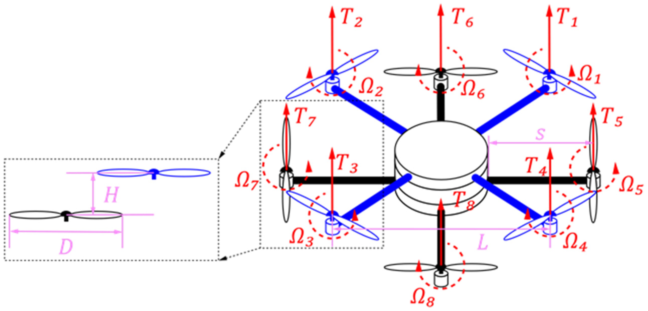
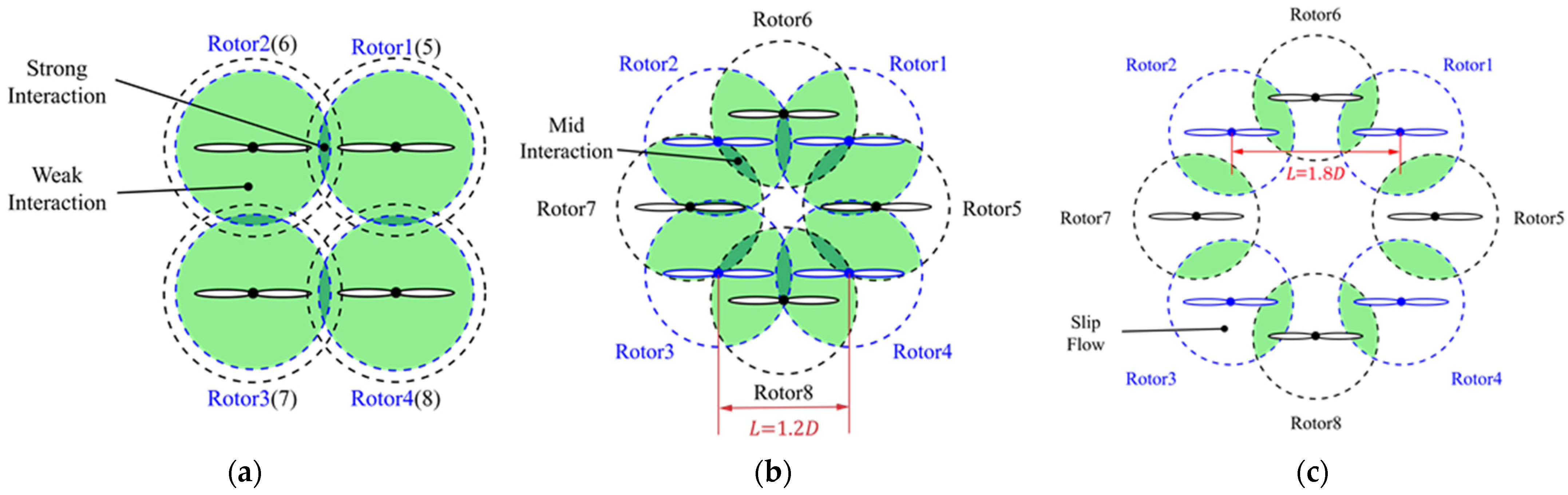
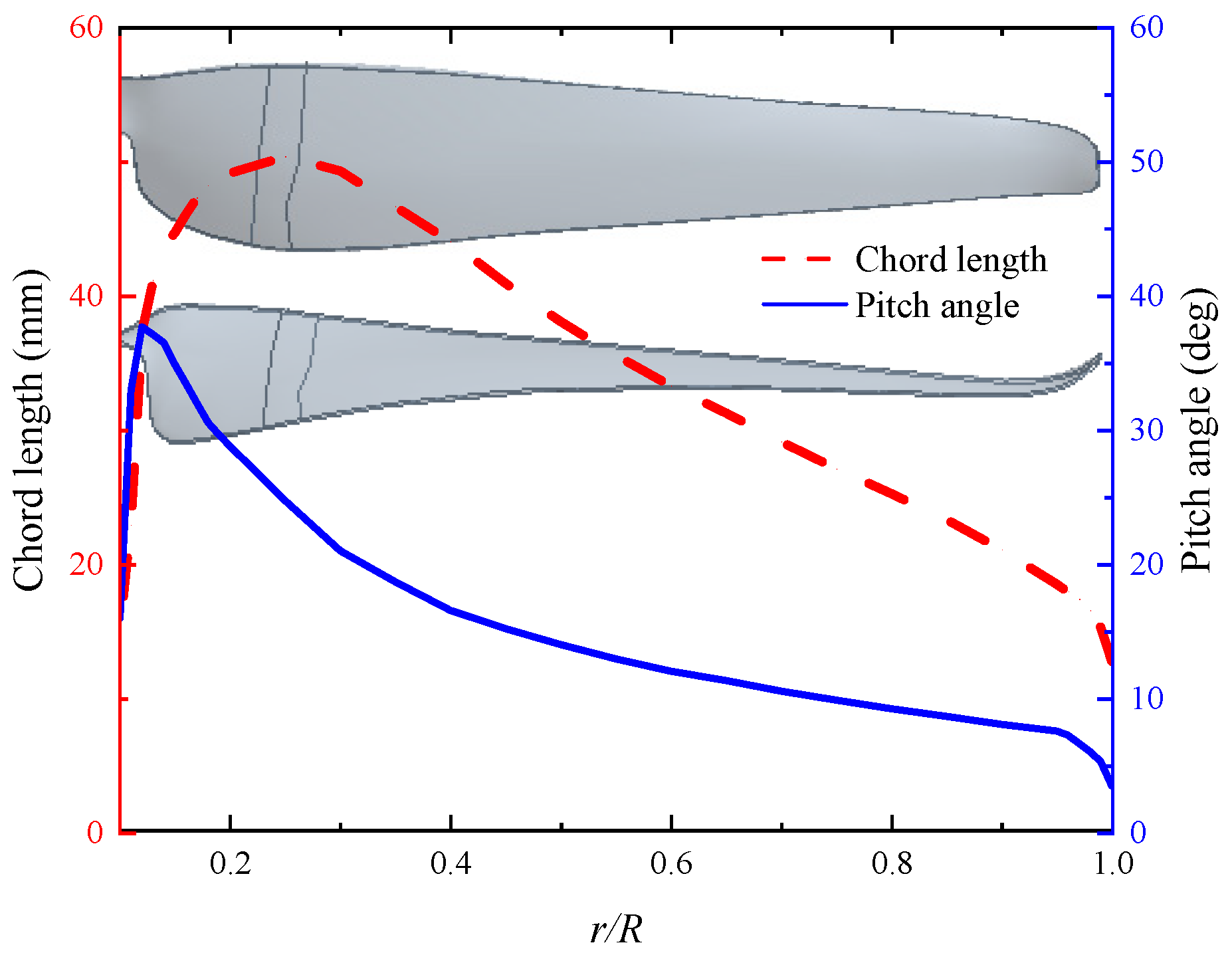
2.1. Aerodynamic Model

As shown in Figure 1, the rotor system of an overlapping octocopter is divided into two layers. Four upper rotors and four lower rotors are located around the center of the vehicle. The angle between the upper rotor arm and lower rotor arm is 45°. Ω is the rotor speed RPM. L is the distance between the rotation centers of the adjacent rotors on the same level. D is the diameter of the rotor. T i represents the thrust of the i -th rotor. s is the length of the rotor arm. H is the distance between the upper rotor and the lower rotor, which is fixed as 0.75 D [18]. Two sets of rotor motors on the diagonal run in the same direction, providing the required thrust and torque for the overlapping octocopter.
Figure 2 shows the flow field of the novel overlapping rotors with two layers compared with traditional co-axial rotors. Considering that there are two layers, the upper rotor will change the original wake of the lower rotor completely, especially when the downwash of the upper rotor interacts with the inflow of the lower rotor. In this case, the increased downwash posed on the lower rotor will definitely change the whole efficiency for a given spacing. Moreover, if the lower rotor operates entirely within the outflow of the upper rotor like the co-axial rotors shown in Figure 2b, it may induce vibrations with extra power consumption and eventually decrease the stability and flight performance of the MAV. Although the rotor interference between two layers is not as strong as the co-axial rotors, the interference from the adjacent rotors will make the aerodynamic environment much more complicated [19].
The sketch of the rotor interference is shown in Figure 3. For the co-axial rotors, the downwash flow from the upper rotor completely impinges on the lower rotor, causing strong interference which will decrease the hover efficiency with more power consumption. For the overlapping case, the rotor interference is weakened without direct impact as compared to the co-axial octocopter. Also, the interaction area of the downwash flow is decreasing with the rotor spacing. Furthermore, the interference between adjacent rotors on the same layer is also reduced with increasing rotor spacing. However, the MAV will be oversized with constantly increasing rotor spacing. Hence, there has to be a suitable tradeoff between improved efficiency to provide sufficient thrust with lower power and reduced payload with increased weight. At last, this requirement has been met by designing a propulsion system with the greatest degree of capacity and aerodynamic performance, allowing the designer to make tradeoffs between the overall propulsive efficiency of the vehicle and the particular application considering the size/weight restriction. Considering that the maximal rotor interference is achieved at L = 1.0 D with a decreasing performance [5], the minimum L = 1.2   D is set to avoid the collision of adjacent rotors, and the maximum L = 2   D is set to avoid oversize of the MAV which is proved to be not beneficial to improving maneuverability. Above all, the spacing L ranges from 1.2   D to 2   D ( D is the diameter of the rotor) with even spacing of 0.2   D , which means that the rotor spacing L is 1.2   D , 1.4   D , 1.6   D , 1.8   D , 2   D , respectively.

2.2. Hover Efficiency

The thrust and the induced velocity of the rotor are obtained by the momentum theorem [20]:
T = 2 π R 2 ρ v 1 2
v 1 = T 2 π R 2 ρ
where R is rotor radius, ρ is air density [kg/m3], v 1 is the induced velocity [m/s], T is thrust [N].
The power consumption introduced by the induced velocity is [20]:
P = T v 1
The dimensionless quantities are:
C T = 4 T ρ A Ω 2 D 2
C P = 8 P ρ A Ω 3 D 3
T = i = 1 8 T i ( i = 1 , 2 , 3 , 4 )
P = Q Ω = i = 1 8 Q i Ω ( i = 1 , 2 , 3 , 4 )
where P is power consumption [W]; A is the area of the rotor disk [m2]; Q is torque.
The figure of merit (FM) is promoted to characterize the hover efficiency considering the thrust and the power consumption [5]. The figure of merit is given by:
F M = C T 3 / 2 C P 2
It can be seen that a better hover efficiency comes from a higher FM with an increased thrust or decreased power consumption. Therefore, thrust T , rotor speed Ω , and the power P are the key parameters measured in experiments.
As a comparison, a co-axial octocopter is introduced in this paper to characterize the potentially improved performance for the overlapping octocopter. The co-axial octocopter is equipped with a fixed co-axial spacing of 50 mm and the adjacent rotor spacing 1.8   D [5]. Both octocopters are used in the same conditions both for experiments and numerical simulations.

3. Experiment

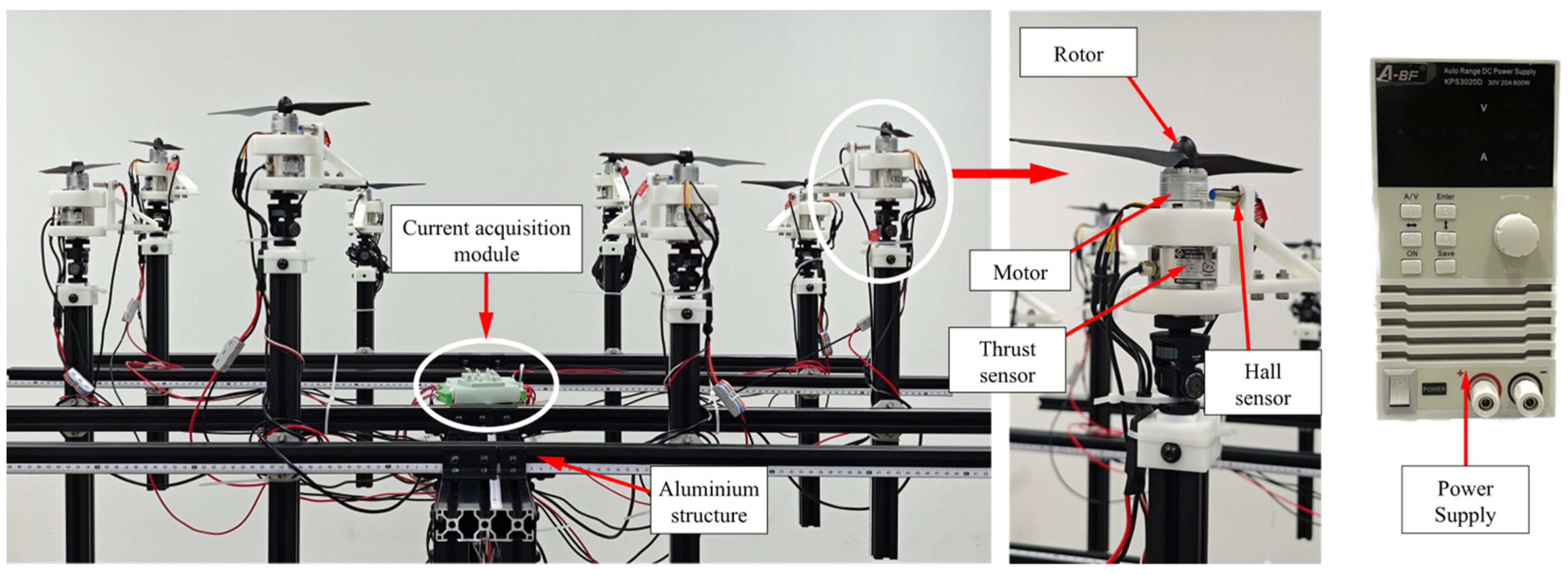
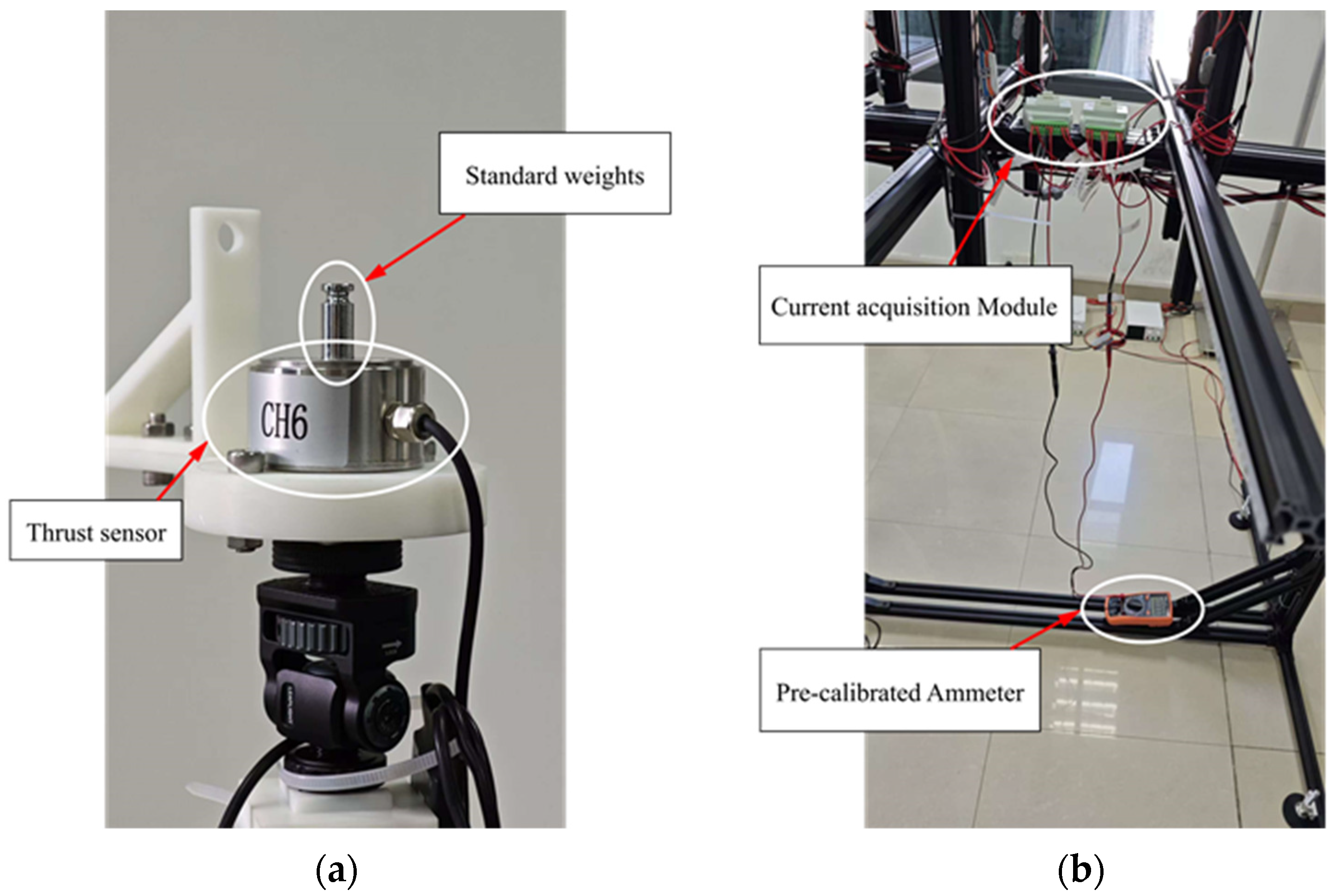
3.1. Experimental Setup

The airfoil profiles and rotor parameters are presented in Figure 4 and Table 1, respectively.
Figure 5 shows the experimental setup to obtain the thrust, speed, and power.
The rotor is driven by a brushless DC motor (model: MSYS-LRK 195.03, Yuanhang Technology Electronics Co., Ltd., Guangzhou, China), and the rotor speed is obtained by a Hall sensor (model: NJK-8001C, Wenzhou Henghui Electric Technology Co., Ltd., Wenzhou, China). Also, the thrust is acquired from the thrust sensor (model: DYZ-101 accuracy: 0.05% F. S, Dayang Sensing System Engineering Co., Ltd., Hefei, China). The power supply provides a stable voltage, and the current of each rotor is obtained through an acquisition module. For each rotor speed, four minutes of data were acquired from the transducers with a rate of 1000 samples/s, and the average values are achieved to eliminate unsteady effects. Furthermore, the measurement was repeated 3 times, until the scatter fell to acceptable levels. The experimental temperature is 25 °C, the atmospheric pressure is 1010 hPa, and the air density is approximately 1.18 kg/m3. Finally, the thrust and power from each run were converted into their non-dimensional coefficient ( C T , C P ) forms to obtain the uncertainty.

3.2. Error Analysis

Thrust sensors and the current acquisition module were calibrated using standard weights and a precalibrated ammeter, respectively, as shown in Figure 6.
The thrust sensors were calibrated while mounted on the test stand to avoid any changes in the calibration factors produced by preloading of the structure. The limits of the thrust values that can be measured by the balance are determined by the maximum rating of the sensors. However, it must be taken into account that the thrust cell is preloaded with the stem/transmission structure. Finally, rotational acceleration of the blades needs to be kept at reasonable values based on their mass.
The main sources of error in the experiments are the standard deviations of the rotational speed and the mean voltages from the thrust sensors. The measurement error of speed is determined by the number of magnets in the motor. For a measurement time t , an error for one pulse with a speed variation of is:
n = 60 m 1 ± 1 p t = 60 m 1 p t ± 60 p t
where n is the rotational speed for the next pulse; m 1 is the number of pulses; p is the number of pulses generated by one rotation.
The relative error ε is [21,22]:
ε = Δ n n = 1 m 1
m 1 = n p t 60
ε = 60 p t 1 n
where ε is relative error; n is the rotational speed; Δ n is the absolute error of speed.
Considering that there are 24 magnets in the motor, p = 24 and the relative error ε = 60 / 24 t n . Typical values of the standard deviations of thrust are about 1% of the mean values. The values of uncertainty presented in this study are all calculated for 95% confidence levels.

3.3. Experimental Results

Figure 7 shows the thrust variation and power variation of the overlapping octocopter compared with traditional co-axial octocopter. It is clear that the thrust of the overlapping octocopter is higher than that of the co-axial octocopter, which indicates that the improved performance for the overlapping octocopter is characterized by a higher payload. The rotor spacing of 1.2   D at 1800 RPM yielded a minimal thrust increment of 12.14%, and the rotor spacing of 1.8   D at 2200 RPM obtained the max thrust increment of 15.98%. The likeliest explanation for this phenomenon is that the rotor interference rose with the increasing rotor spacing and only partial downwash flow impinged on the lower rotor. Thus, the interaction offset the thrust loss on the lower rotor and increased the induced velocity accordingly. Based on Equation (1), this will lead to the thrust increment with proper interference from an optimal rotor spacing. Also, the power consumption increased with the rotor speed and obtained a higher value than that of the co-axial octocopter. Compared with the co-axial octocopter, the lowest power consumption for the overlapping octocopter is observed at 2.0   D for 1500 RPM which declined by 5.36%. The power increment achieved a maximum of 19.03% at 1.2   D with 2300 RPM. This may be caused by the stronger rotor interference for a smaller rotor spacing where the suction forces on the blade tip collapsed with the increase in vibration and leading to the flow separation. In this case, the rotor is apt to have somewhat greater interaction with its own wake. This heightened interaction is reflected in the greater vibration when increasing power consumption, especially for a higher rotor speed.
Figure 8 shows the FM variation of the overlapping octocopter compared with the co-axial octocopter. FM (%) is the FM increment of the overlapping octocopter compared with the co-axial octocopter in the same condition. Clearly, the FM of the overlapping octocopter is higher than that of the co-axial octocopter and it is up to 10% at 1800 RPM. In this case, the proper interference is leading to increasing thrust. Furthermore, L = 1.2   D presented a lower FM and shared a similar FM for a higher rotor speed. Considering that the vortex movement in the outflow is much faster at a higher rotor speed than 2200 RPM, it accelerates the deformation of the vortex. From this aspect, the overlapping octocopter may not be suitable for a hover flight with higher rotor speed.
To show the optimal rotor spacing for the overlapping arrangement, the FM distribution is shown in Figure 9. It is noted that the rotor spacing L = 1.8 D obtained a higher FM for all the rotor speeds and it reached the maximum at 1800 RPM. This trend indicated that the overlapping octocopter obtained the best hover efficiency with a rotor speed around 1800 RPM at 1.8   D . Thus, the flow distribution considering the rotor interference with the optimal rotor spacing of 1.8   D at 1800 RPM needs verification from numerical simulations.

4. Numerical Simulations
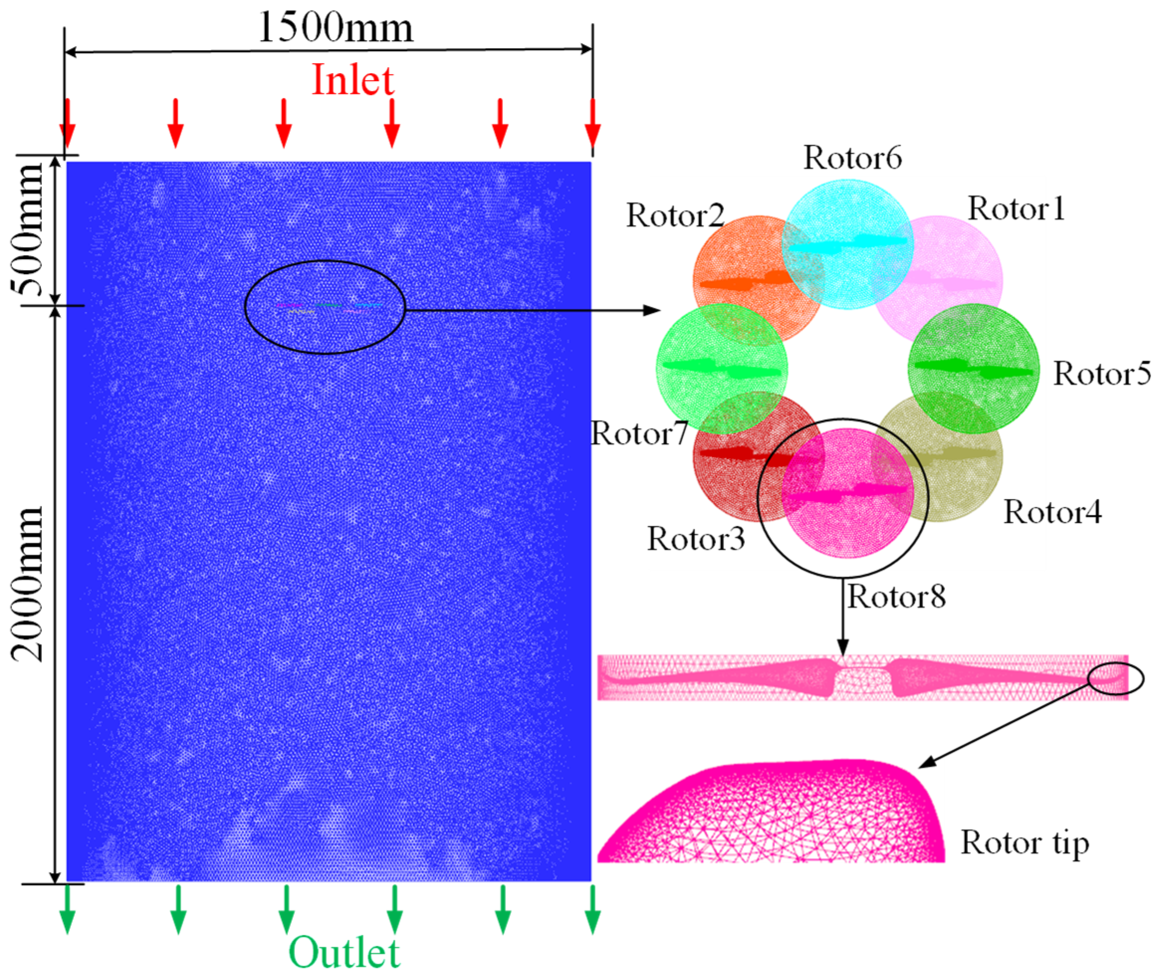
4.1. Setup

Numerical simulations are performed with ANSYS FLUENT (2021R1) and the rotor speed ranges from 1500 to 2300 RPM. The computational domain is divided into eight rotating regions and one stationary region. The octocopter is located in the upper part of the domain to obtain more detail of the downwash flow. Additionally, sliding mesh is applied to perform unsteady analysis with multiple viscous boundary layers to refine the mesh and reach the independence state. The first boundary layer thickness of the mesh is 7.8 × 10 6 m, with an average wall y + value of 4.79. Finally, there are 29 million meshes with the max element skewness of 0.8. The mesh distribution and boundary conditions are shown in Figure 10.
For numerical simulations, the Reynolds-averaged SST k-omega is applied as the turbulence model for the flow field. The PISO algorithm is adopted for all transient flow calculations. Also, PRESTO discretization gives more accurate results than standard since interpolation errors and pressure gradient assumptions on the boundaries are avoided. The time step based on the dimensionless Courant–Friedrichs–Lewy (CFL) condition number is used for all simulations. Furthermore, the second order discretization schemes are utilized for the time discretization and also preventing any unnecessary fluctuations in the solution fields.

4.2. Simulation Results

The numerical simulation is verified by the experiment with thrust and power as shown in Figure 11. Results showed that they were generally in good agreement within a relative error of 5%.
Table 2 shows the key parameters of the octocopter at 1800 RPM. It can be seen that C T , C P , and FM of the overlapping octocopters increased with the rotor spacing and obtained the maximum at 1.8   D . Compared with the co-axial octocopter, the overlapping octocopter showed a better hover efficiency with a higher FM.
Figure 12 shows the thrust variation of the overlapping octocopter and co-axial octocopter within one rotation cycle.
It can be seen that the total thrust of the overlapping octocopter is higher than that of the co-axial octocopter with an increment of 24%. Also, the thrust variation of the overlapping octocopter is relatively small which is advantageous to keep the stability without extra power consumption. In contrast, the thrust of the co-axial octocopter presented a sudden change between 180 to 240 degrees which will suffer a much stronger rotor interference caused by the impact both from the upper rotor and adjacent rotor and lead to a variation with power increment thereafter.
To present the flow field affected by both the upper rotor and adjacent rotor, the velocity distribution of the downwash flow is crucial for the aerodynamic improvement to characterize the rotor interference. Figure 13 shows the velocity distribution of the downwash flow for both the co-axial octocopter and overlapping octocopter.
For the co-axial octocopter shown in the Figure 13a, the inflow of the lower rotor is completely immerged with the downwash flow from the upper rotor which increased the local velocity by stronger interactions. In this case, the efficiency of the lower rotor is decreased by increasing power consumption which is consistent with the momentum theory in hover. For the novel overlapping octocopter, the downwash flow from the upper rotor is diffused with a partial impact on the lower rotor. The rotor interference from both the upper rotor and the adjacent rotor is weakened with the increase in rotor spacing. The potential advantage of the rotor interference is observed at the rotor spacing of 1.8 D which is characterized by evenly distributed velocity. Combined with the experimental results, this thrust increment may be related to the downwash distribution. As the rotor spacing continuously increases, the disk area is increased with a scattered induced velocity, which not only increases the weight but also reduces the airflow interference between the rotors, leading to a decrease in downwash velocity and ultimately a lower hover efficiency.
Figure 14 shows the tip velocity distribution of the overlapping octocopter at 1800 RPM.
As shown in the Figure 14, the maximal velocity difference is observed at L = 1.2   D where rotor 2 and rotor 6 suffered thrust decrement affected by the rotor interference. Additionally, the velocity is evenly distributed for all eight rotors at L = 1.8   D which indicated the potential stability of this rotor spacing.
The pressure distribution of a lower rotor (rotor 1) is shown in Figure 15 to present the thrust variation affected by the upper rotor.
It can be seen that the negative pressure is mainly concentrated on the upper surface of the rotor, and the large pressure difference will increase thrust. For the co-axial rotor, the pressure distribution on the lower rotor is very irregular due to the impact of the outflow from the upper rotor, which is disadvantageous to the thrust generation. For the novel overlapping octocopter, the pressure distribution is more uniform at L = 1.8 D with a greater pressure difference between the upper and lower surfaces of the rotor. Therefore, the thrust performance at L = 1.8 D is optimal for the overlapping arrangement.
Figure 16 shows the distribution of streamlines along with the downwash flow.
Due to the stronger rotor interference between the upper and lower rotor, the velocity of the downwash flow increased dramatically for the co-axial octocopter which will cause vibration with increasing power consumption. For the overlapping octocopter, the vortex distribution is symmetric which is beneficial for the flight stability. However, there is a vortex deformation for both L = 1.6 D and L = 2.0 D which will lead to the vortex movement and cause vibration with extra power consumption, or even offset the rotor interference with power increment. The symmetric vortex observed at L = 1.8   D indicates that this rotor spacing is optimal for the overlapping octocopter, as also supported by experimental results showing the highest FM.

5. Conclusions

A novel overlapping octocopter with better payload capacity and hovering efficiency has been proposed in this paper. Both experiments and numerical simulations are performed to obtain the optimal adjacent rotor spacing by comparison with a traditional co-axial octocopter. To answer the three hypothetical questions presented in the Introduction, conclusions are given below:
(1)
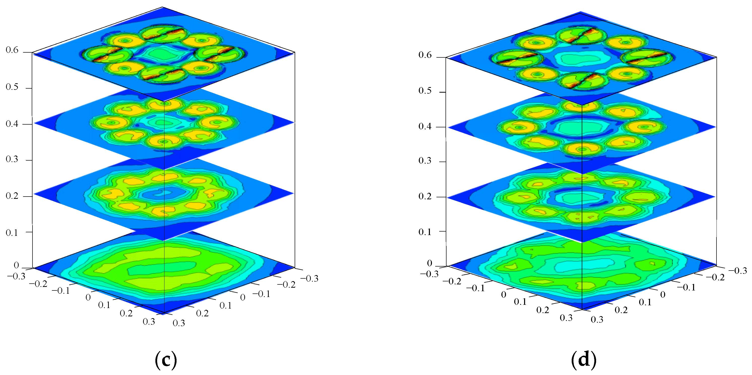
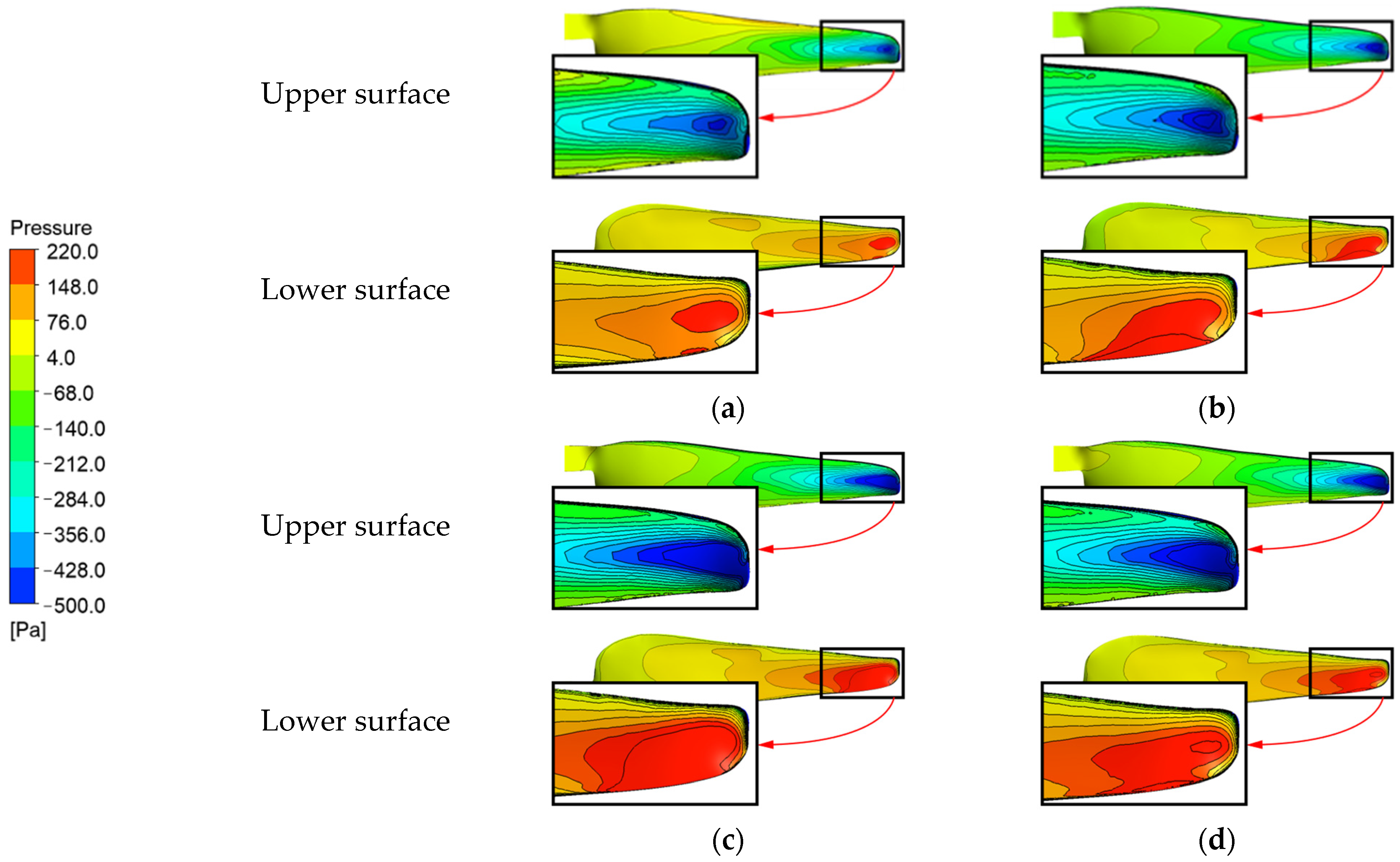
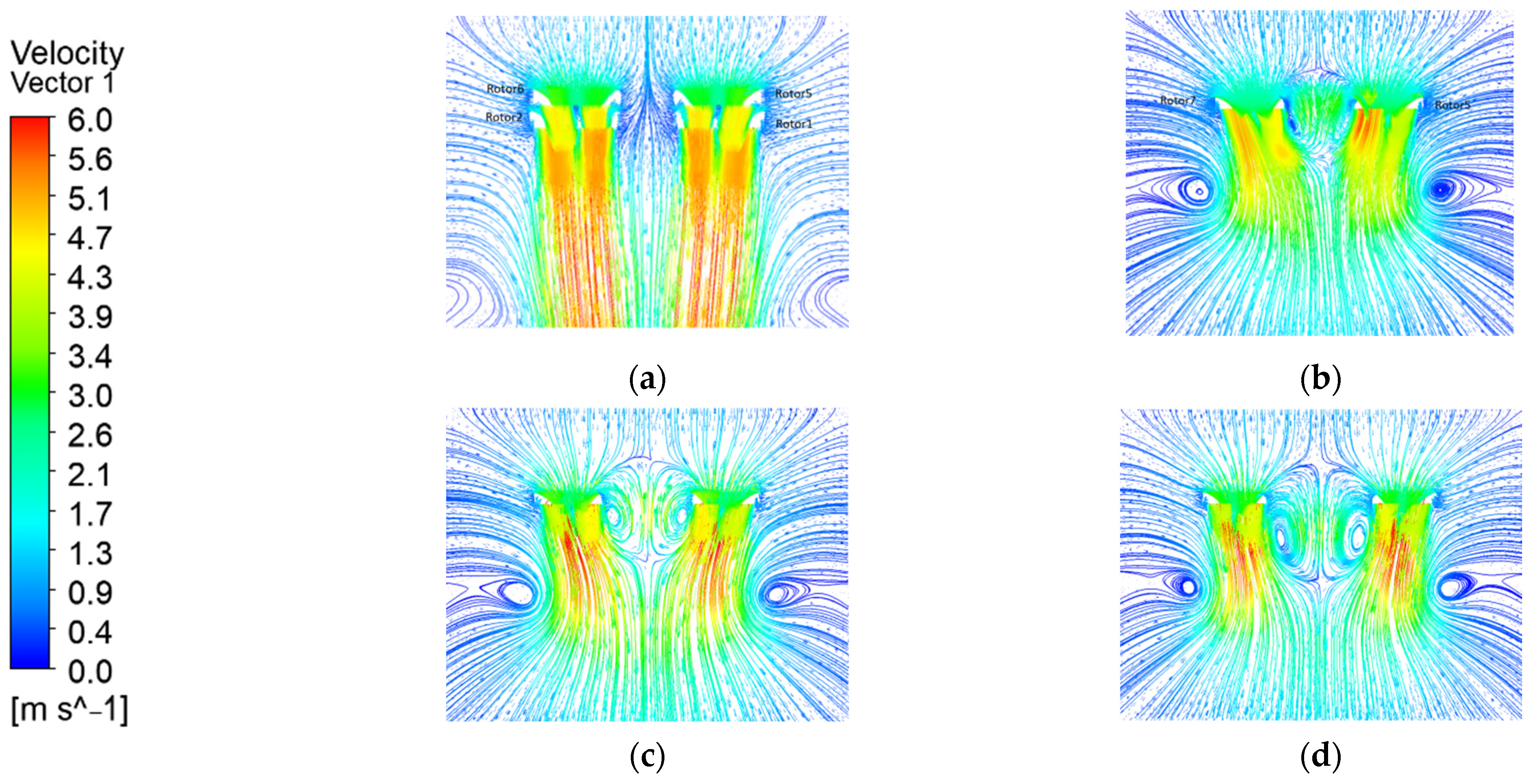
Effect of rotor spacing on the propulsive efficiency: The rotor interference is decreased with the increasing rotor spacing and resulting in different thrust and power changes. A full or symmetrical shape of the vortex from the downwash flow leads to a steady power consumption. The vortex deformation resulting from the movement of the vortex may cause vibration and lead to extra power consumption. Also, the effect of the interference on the thrust is focused on the pressure of the lower surface of the rotor. This proved to achieve a higher efficiency with a maximum thrust/power ratio and minimum weight at the same time.
(2)
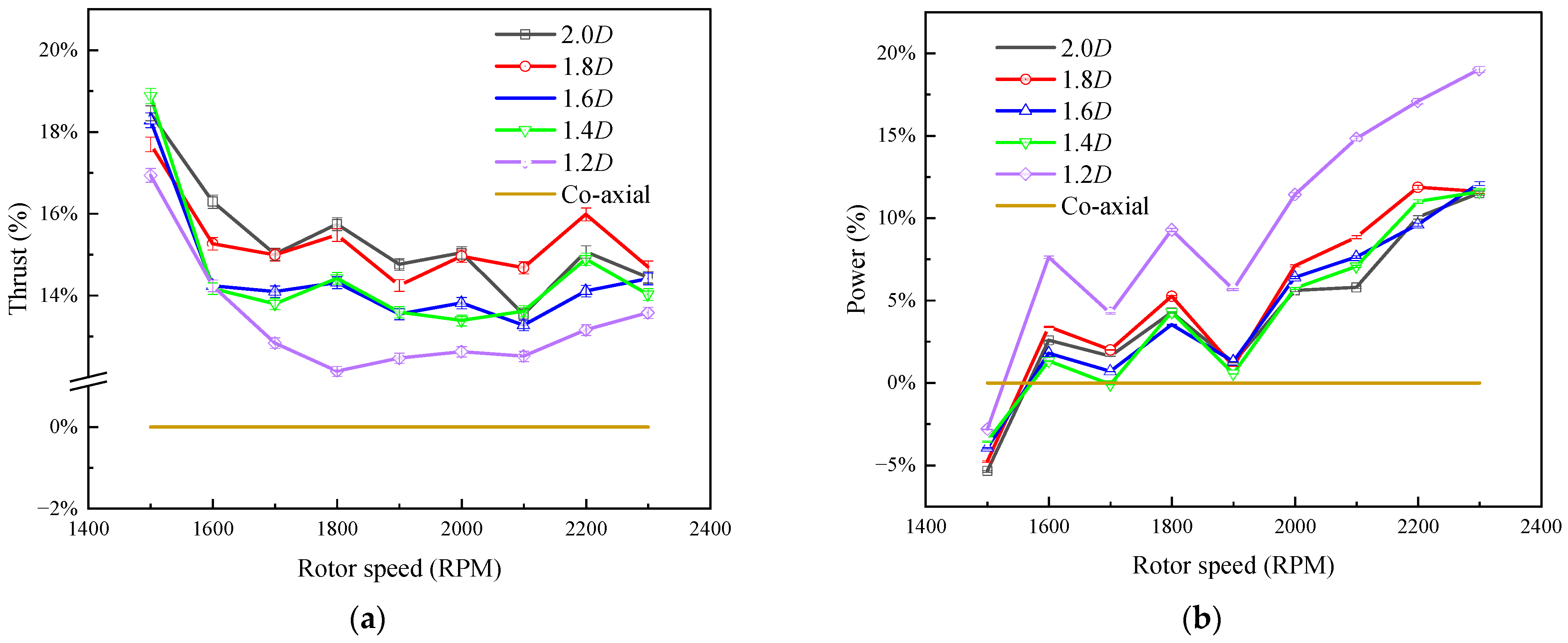
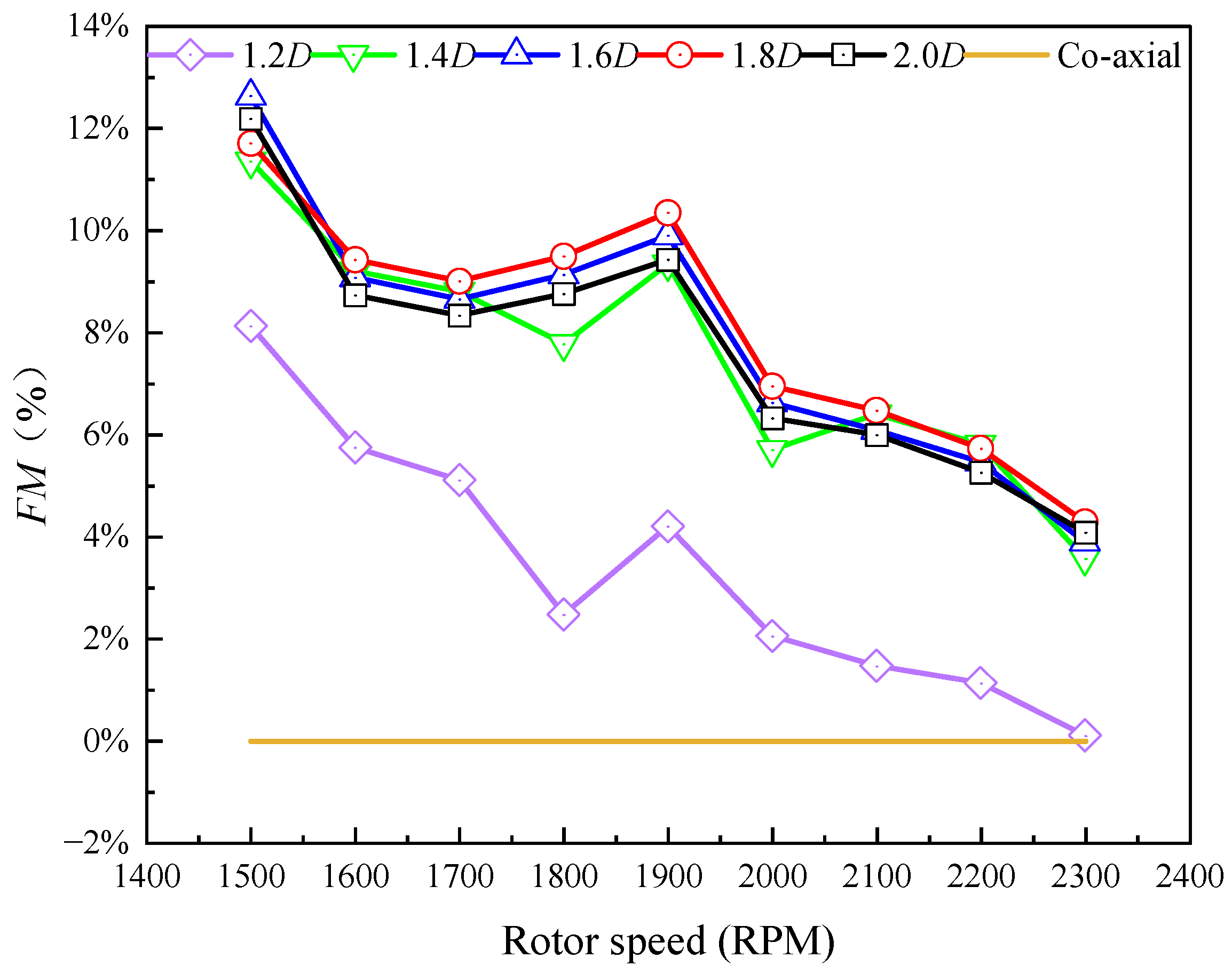
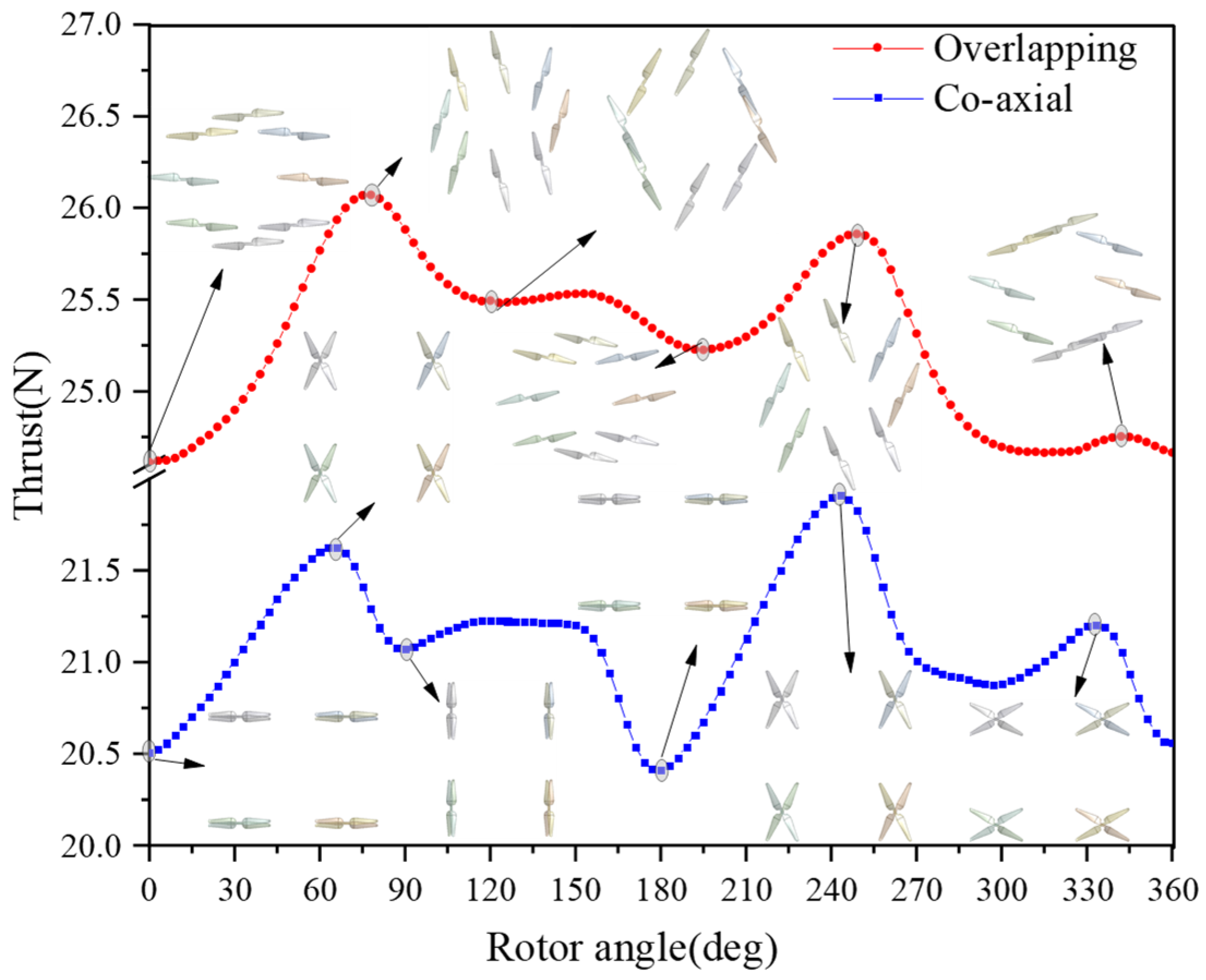
Aerodynamic interference and thrust increment: The overlapping octocopter with rotor spacing ranging from 1.2 D to 2.0 D experienced more thrust (up to 15.9%) with higher FM (up to 6%) than the co-axial octocopter. It obtained the highest FM at 1800 RPM with a rotor spacing of 1.8 D which enhanced the performance for the novel overlapping octocopter. Also, it is noted that the FM declined with the rotor speed higher than 2000 RPM which indicated that it is not suitable for flight with high rotor speed. In this case, the increment of the rotor interference may cause vibration and lead to extra power consumption, especially for L = 2.0 D. From the aerodynamic perspective, the potential benefit of the aerodynamic interference comes from the mutual interference along with the downwash flow from the upper rotor and the original flow from the adjacent rotor with proper rotor spacing.
(3)
Optimal rotor spacing for improved hover efficiency: The optimal rotor spacing for the overlapping octocopter is 1.8 D and it is interesting to note that the compact area of the downwash flow from upper rotor is related of the vortex deformation and movement in the streamline. The symmetric vortices were evenly distributed within the downwash flow, which is advantageous to mitigate rotor interference, thereby enhancing thrust generation with minimal power increase. As a result, the overlapping octocopter with a rotor spacing of L = 1.8 D and a rotor speed of 1800 RPM achieved the maximum hover efficiency.
Our studies will go further by introducing the effect of wind disturbance in the engineering design and conducting series theoretical derivations trying to amend the conventional control theory with more field flight tests. In the stratified optimization case, the aerodynamic model for simulation in this paper is just fit for purpose for a benign case of level hover. When it comes to a more extreme flight or with wind gusts, the aerodynamic performance is changed and it needs more sufficient way to consider the effect of the rotor interference for this new overlapping octocopter.

Author Contributions

Investigation, review and editing, Y.L.; writing and software, X.Z. All authors have read and agreed to the published version of the manuscript.

Funding

This research was supported by the National Natural Science Foundation of China (Grant No. 52275095) and Fujian Provincial Industrial Robot Basic Components Technology Research and Development Center (2014H2004).

Data Availability Statement

All data are already included in the manuscript.

Acknowledgments

The authors thank the Key Laboratory of Fluid Power and Intelligent Electro-Hydraulic Control (Fuzhou University), Fujian Province University for supplying the experimental field.

Conflicts of Interest

The authors declare no conflicts of interest.

References

  1. Ruiz, M.C.; Scanavino, M.; D’Ambrosio, D.; Guglieri, G.; Vilardi, A. Experimental and numerical analysis of hovering multicopter performance in low-Reynolds number conditions. Aerosp. Sci. Technol. 2022, 128, 107777. [Google Scholar] [CrossRef]
  2. Cozma, A.; Firculescu, A.-C.; Tudose, D.; Ruse, L. Autonomous multi-rotor aerial platform for air pollution monitoring. Sensors 2022, 22, 860. [Google Scholar] [CrossRef]
  3. Klimczyk, W.; Sieradzki, A. RANS-Based Aeroacoustic Global Sensitivity Study and Optimization of UAV Propellers. Aerospace 2023, 10, 306. [Google Scholar] [CrossRef]
  4. Prior, S.D. Reviewing and investigating the use of co-axial rotor systems in small UAVs. Int. J. Micro Air Veh. 2010, 2, 1–16. [Google Scholar] [CrossRef]
  5. Lei, Y.; Ji, Y.; Wang, C. Optimization of aerodynamic performance for co-axial rotors with different rotor spacings. Int. J. Micro Air Veh. 2018, 10, 362–369. [Google Scholar] [CrossRef]
  6. Zhang, H.; Tan, S.; Song, Z.; Quan, Q. Performance evaluation and design method of lifting-wing multicopters. IEEE/ASME Trans. Mechatron. 2021, 27, 1606–1616. [Google Scholar] [CrossRef]
  7. Riboldi, C.E. An optimal approach to the preliminary design of small hybrid-electric aircraft. Aerosp. Sci. Technol. 2018, 81, 14–31. [Google Scholar] [CrossRef]
  8. AL-Dosari, K.; Hunaiti, Z.; Balachandran, W. Systematic review on civilian drones in safety and security applications. Drones 2023, 7, 210. [Google Scholar] [CrossRef]
  9. Qin, T.; Zhang, G.; Yang, L.; He, Y. Research on the Endurance Optimisation of Multirotor UAVs for High-Altitude Environments. Drones 2023, 7, 469. [Google Scholar] [CrossRef]
  10. Theys, B.; Dimitriadis, G.; Hendrick, P.; De Schutter, J. Influence of propeller configuration on propulsion system efficiency of multi-rotor Unmanned Aerial Vehicles. In Proceedings of the 2016 International Conference on Unmanned Aircraft Systems (ICUAS), Arlington, VA, USA, 7–10 June 2016; pp. 195–201. [Google Scholar]
  11. Serré, R.; Gourdain, N.; Jardin, T.; Jacob, M.C.; Moschetta, J.-M. Towards silent micro-air vehicles: Optimization of a low Reynolds number rotor in hover. Int. J. Aeroacoustics 2019, 18, 690–710. [Google Scholar] [CrossRef]
  12. Yeong, S.P.; Dol, S.S. Aerodynamic optimization of micro aerial vehicle. J. Appl. Fluid Mech. 2016, 9, 2111–2121. [Google Scholar] [CrossRef]
  13. Throneberry, G.; Takeshita, A.; Hocut, C.; Shu, F.; Abdelkefi, A. Multi-rotor wake characterization and visualization in ascending and descending flight. Exp. Fluids 2022, 63, 98. [Google Scholar] [CrossRef]
  14. Yang, H.; Xia, W.; Wang, K.; Hu, S. Aerodynamic performance of a small-scale tilt rotor: Numerical simulation and experiment in steady state. Proc. Inst. Mech. Eng. Part C J. Mech. Eng. Sci. 2023, 237, 4141–4150. [Google Scholar] [CrossRef]
  15. Ruiz, M.C.; D’Ambrosio, D. Aerodynamic optimization and analysis of quadrotor blades operating in the Martian atmosphere. Aerosp. Sci. Technol. 2023, 132, 108047. [Google Scholar] [CrossRef]
  16. Kim, H.W.; Brown, R.E. A comparison of coaxial and conventional rotor performance. J. Am. Helicopter Soc. 2010, 55, 12004. [Google Scholar] [CrossRef]
  17. Nandakumar, G.; Saphal, R.; Joishy, A.; Thondiyath, A. Performance analysis of vertically offset overlapped propulsion system based quadrotor in an aerial mapping mission. Int. J. Micro Air Veh. 2018, 10, 370–385. [Google Scholar] [CrossRef]
  18. Lei, Y.; Wang, J.; Li, Y. The aerodynamic performance of a novel overlapping octocopter considering horizontal wind. Aerospace 2023, 10, 902. [Google Scholar] [CrossRef]
  19. Barakos, G.; Garcia, A.J. CFD analysis of hover performance of rotors at full-and model-scale conditions. Aeronaut. J. 2016, 120, 1386–1424. [Google Scholar] [CrossRef]
  20. Bangura, M.; Melega, M.; Naldi, R.; Mahony, R. Aerodynamics of rotor blades for quadrotors. arXiv 2016, arXiv:1601.00733. [Google Scholar]
  21. Prothin, S.; Fernandez Escudero, C.; Doué, N.; Jardin, T. Aerodynamics of MAV rotors in ground and corner effect. Int. J. Micro Air Veh. 2019, 11, 1756829319861596. [Google Scholar] [CrossRef]
  22. Leishman, J.G.; Syal, M. Figure of merit definition for coaxial rotors. J. Am. Helicopter Soc. 2008, 53, 290–300. [Google Scholar] [CrossRef]
Figure 1. The overlapping octocopter.
Aerospace 11 00737 g001
Figure 2. Flow field of the rotor pair in an octocopter. (a) Overlapping octocopter; (b) Co-axial octocopter as comparison.
Aerospace 11 00737 g002
Figure 3. Interaction area. (a) Co-axial octocopter; (b) Overlapping octocopter at L = 1.2   D ; (c) Overlapping octocopter at L = 1.8   D .
Aerospace 11 00737 g003
Figure 4. Rotor profile.
Aerospace 11 00737 g004
Figure 5. Experimental setup.
Aerospace 11 00737 g005
Figure 6. Sensor calibration. (a) Thrust sensor; (b) Current acquisition module.
Aerospace 11 00737 g006
Figure 7. Thrust and power variation of the overlapping octocopter compared with the co-axial octocopter: (a) Thrust variation; (b) power variation.
Aerospace 11 00737 g007
Figure 8. The FM variation of the overlapping octocopter compared with the co-axial octocopter.
Aerospace 11 00737 g008
Figure 9. FM variation of the overlapping octocopter.
Aerospace 11 00737 g009
Figure 10. Mesh distribution.
Aerospace 11 00737 g010
Figure 11. Validation of numerical simulations ( L = 1.8   D ). (a) Thrust; (b) Power.
Aerospace 11 00737 g011
Figure 12. Thrust variation within one rotation cycle.
Aerospace 11 00737 g012
Figure 13. Velocity distribution of the downwash flow. (a) Co-axial octocopter; (b) Overlapping octocopter with L = 1.6   D ; (c) Overlapping octocopter with L = 1.8   D ; (d) Overlapping octocopter with L = 2.0   D .
Aerospace 11 00737 g013aAerospace 11 00737 g013b
Figure 14. Tip velocity of the overlapping octocopter at 1800 RPM.
Aerospace 11 00737 g014
Figure 15. Pressure distribution on the lower rotor (rotor 1). (a) Co-axial octocopter; (b) Overlapping octocopter with L = 1.6 D ; (c) Overlapping octocopter with L = 1.8 D ; (d) Overlapping octocopter with L = 2.0 D .
Aerospace 11 00737 g015
Figure 16. Streamline distribution. (a) Co-axial octocopter; (b) Overlapping octocopter with L = 1.6 D ; (c) Overlapping octocopter with L = 1.8 D ; (d) Overlapping octocopter with L = 2.0 D .
Aerospace 11 00737 g016
Table 1. Rotor parameters.
ParameterValue
Diameter400 mm
Weight0.015 kg
MaterialCarbon fiber
Number of blades2
Chord length (75% R )0.028 m
Rotor speed1500–2300 RPM
Reynolds number (75%R) 0.4 0.62 × 10 5
Rotor solidity0.128
Twist0
Tip Mach number0.1~0.15
Table 2. Key parameters of the octocopter.
Octocopter C T (10−3) C P (10−3) F M
Co-axial12.95741.50800.6916
Overlapping 1.2   D 14.52541.66720.7425
Overlapping 1.4   D 14.82031.64450.7758
Overlapping 1.6   D 14.80661.63500.7792
Overlapping 1.8   D 14.99181.65030.7865
Overlapping 2.0   D 14.95751.64890.7845
Disclaimer/Publisher’s Note: The statements, opinions and data contained in all publications are solely those of the individual author(s) and contributor(s) and not of MDPI and/or the editor(s). MDPI and/or the editor(s) disclaim responsibility for any injury to people or property resulting from any ideas, methods, instructions or products referred to in the content.

