Article

Large Debris Removal: Using Features of Attitude Motion for Load Factor Regulation during Re-Entry

by
Vladimir S. Aslanov
1,* and
Dmitry A. Sizov
2
1
Mechatronics and Theoretical Mechanics Department, Moscow Aviation Institute (National Research University), 4, Volokolamskoye Shosse, Moscow 125993, Russia
2
Department of Mechanical and Aerospace Engineering, School of Engineering and Digital Sciences, Nazarbayev University, 53, Kabanbay Batyr Ave., Astana 010000, Kazakhstan
*
Author to whom correspondence should be addressed.
Aerospace 2024, 11(9), 786; https://doi.org/10.3390/aerospace11090786
Submission received: 6 August 2024 / Revised: 16 September 2024 / Accepted: 21 September 2024 / Published: 23 September 2024
(This article belongs to the Section Astronautics & Space Science)

Abstract

:
This paper focuses on the active removal of spent upper stages from LEO using de-orbiting devices. It proposes a method of regulating aerodynamic loads on the target during its re-entry by utilizing the features of spatial attitude motion. A mathematical model of the re-entry process is developed, and numerical simulations are conducted, demonstrating that the nature of the attitude motion during the descent influences the load factors and, thus, the breakup altitude. It is shown that the respective de-orbiting devices should control both the initial tumbling and spin of the target to achieve different mission outcomes, such as minimizing the debris footprint size or maximizing the breakup altitude.

1. Introduction

Large space debris objects typically include non-operational satellites and spent upper stages (rocket bodies). Massive removal of old satellites can be challenging in the sense that many satellites are unique in terms of shape and dimensions. Conversely, rocket bodies are numerous and have more or less the same shape and mass-inertial characteristics, which makes them primary targets for future removal missions and justifies the present paper’s focus on spent upper stages. These objects are some of the most hazardous classes of Low Earth Orbit (LEO) debris. As of 16 April 2023, the total number of rocket bodies in LEO was about 6400 [1]. They are massive and prone to spontaneous explosions, so they are a significant potential source of small, hard-to-track space debris posing a threat to operational spacecraft. On the other hand, uncontrolled re-entries of the rocket bodies may endanger ground objects as well, so the occurring re-entries need to be carefully analyzed in order to predict future events [2,3].
There is a wide variety of proposed space debris removal methods [4] using space tethers [5,6,7,8], including tether-net [9,10] or tether-harpoon [11,12,13,14] systems and various de-orbiting modules attached to the targets using controllable dry adhesives [15] or space manipulators (robotic arms) [11,16,17,18]. Another popular idea involving docking is to use flexible beams [19] or other devices [20,21] to attach the de-orbiting module to the nozzle of the target rocket body.
In the case of LEO debris, the final phase of any removal mission is the target’s burn-up in the atmosphere. Re-entry of passive and active spacecraft is a widely studied topic, with the most current research papers being focused on different aspects of the design of re-entry capsules and very low earth orbit satellites [22,23,24,25,26,27,28,29,30]. At the same time, there is a lack of studies investigating the re-entry of rocket bodies. Ref. [6] considers one of such re-entry cases, but only for a planar tumbling of the target during the descent.
The aim of the present article is to investigate the case of the spatial attitude motion of rocket bodies during re-entry and to propose a way of using the features of the attitude motion for the regulation of the aerodynamic loads on the target. In order to achieve this goal, we will develop a mathematical model of the rocket body re-entry, numerically simulate this process for different initial conditions, analyze the simulation results, and then, based on these, formulate possible removal scenarios exploiting the influence of the parameters of the attitude motion on the aerodynamic load factors.
The novelty of the paper is that, using a mathematical model of the spatial attitude motion of the solid body during re-entry, it links the initial conditions of the attitude motion of an old rocket body with the load factors that are critical for its structural integrity, and suggests ways to take advantage of both low and high load factors.
This study has the following structure. Section 2 contains an overview of a typical spent upper stage removal mission involving a de-orbiting device. In Section 3, a mathematical model of the upper stage re-entry is developed, exploiting the body’s dynamic and aerodynamic symmetry. Section 4 is devoted to a case study, where numerical simulations for a typical rocket upper stage are performed and analysed. In the following Section 5, the possibility of using different features of attitude motion for load factor regulation is discussed, and two different mission scenarios exploiting the benefits of low and high load factors are proposed. Finally, the conclusions are given in Section 6.
The key ideas of this paper were presented on 7 June 2024 at the AeroThermoDynamics and Design for Demise (ATD3) Workshop organized by the European Space Agency (ESA) and Centre National d’Etudes Spatiales (CNES).

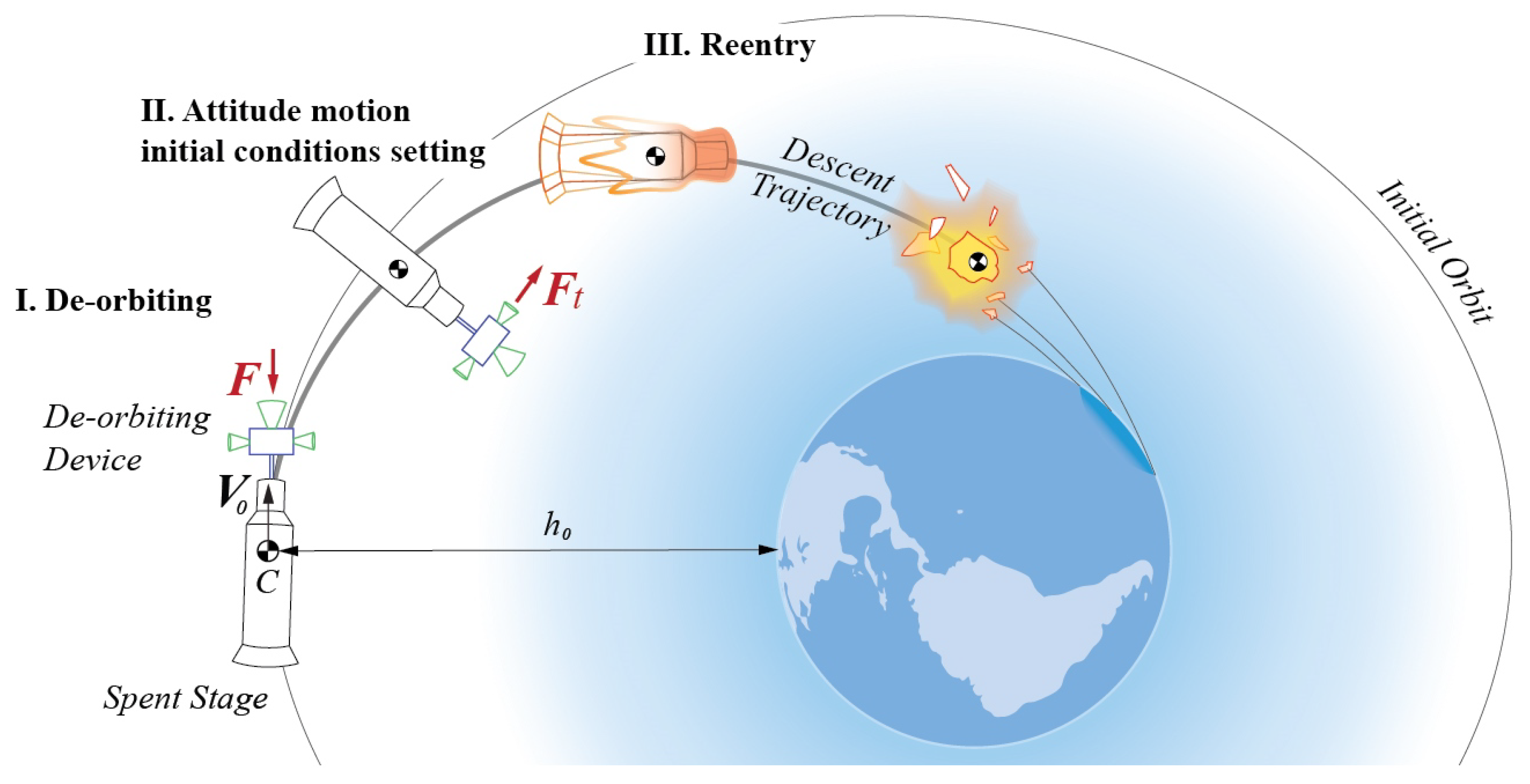
2. Spent Upper Stage Removal Mission Overview

Consider an old upper stage removal mission involving a dockable de-orbiting device. For convenience, let us divide the in-orbit operation into three phases (Figure 1): (1) docking and de-orbiting; (2) forming of the initial state of the target’s attitude motion; and (3) free re-entry of the target.
In the first phase, the docked de-orbiting device creates a negative delta-v in order to transfer the target from its initial orbit onto a re-entry trajectory. The technical aspects of this phase have been widely discussed in the literature [11,15,17,18,19,20,21] and are beyond the scope of the present paper. In terms of simulation, this phase results in the initial conditions of the motion of the center of mass (CoM) of the target.
During the second phase, the de-orbiting device prepares the target for a re-entry by setting the initial conditions of the target’s attitude motion during descent. It can be performed using attitude thrusters and other devices able to control the target’s rotation.
Finally, the device separates from the target, and the latter begins its free descent, during which it eventually breaks up due to the increase in the aerodynamic loads. The critical loads that determine the breakup altitude depend strongly on the structural characteristics of the specific target, so, in this paper, the breakup itself will not be analyzed. Instead, based on the assumption that higher aerodynamic loads result in higher breakup altitudes, we will focus on the attitude motion during the re-entry and the influence of its initial conditions on the aerodynamic loads.

3. Mathematical Model of Re-Entry

3.1. Key Assumptions

The re-entry process of an upper stage is considered under the following assumptions:
  • During re-entry, the gravitational torque is negligibly small compared to the aerodynamic one.
  • We consider only mechanical/aerodynamic loads caused by the descent.
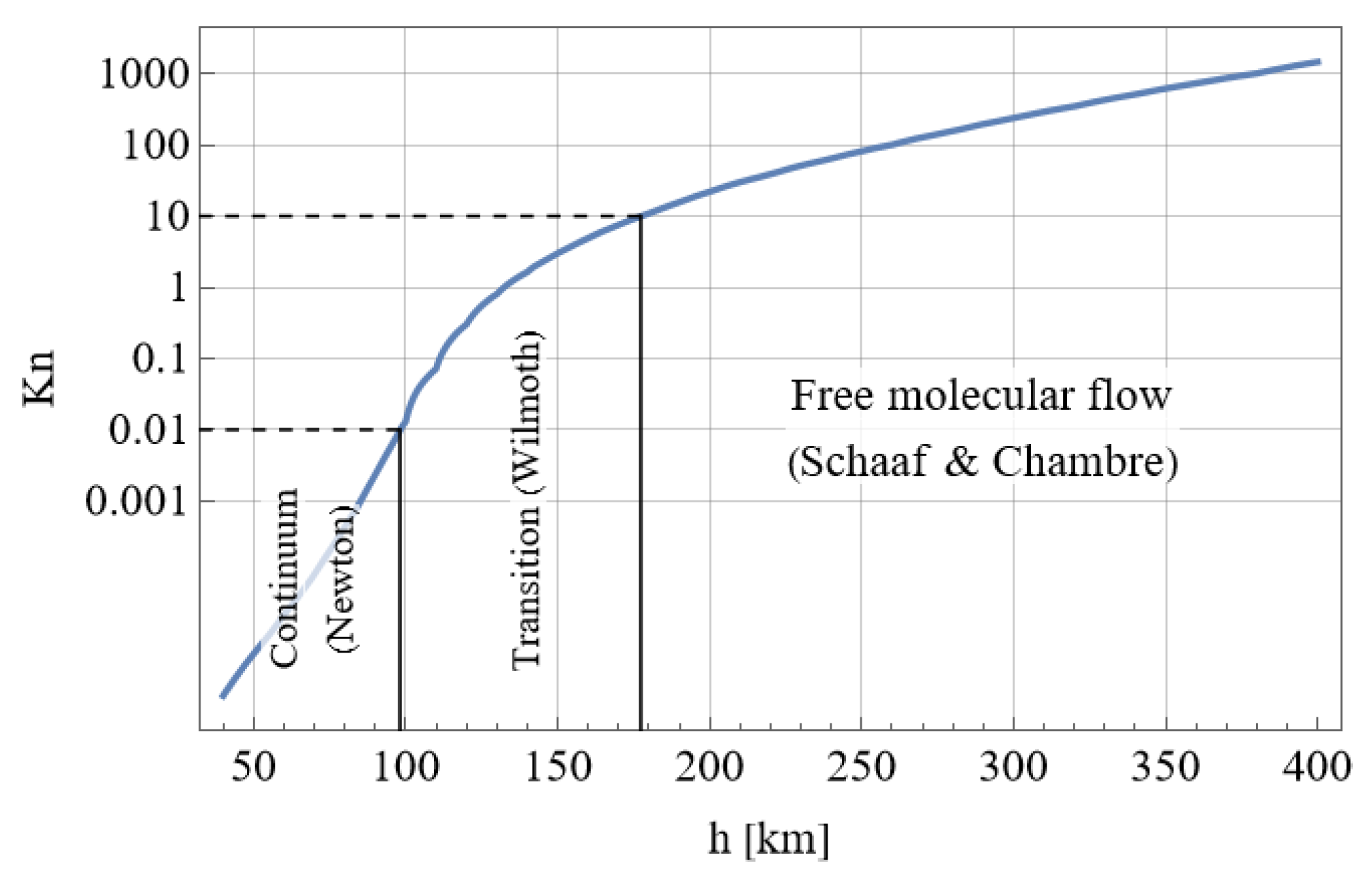
  • The density and temperature of the Earth’s atmosphere change with altitude according to the US Standard Atmosphere Model [31].
  • The atmosphere is not rotating.
  • The target is shaped as a body of revolution with its CoM on the longitudinal axis of symmetry and the transverse moments of inertia equal to each other.
  • The target’s CoM moves in a single plane passing through the Earth’s center.
It should be noted that the fourth assumption is supported by the fact that the rotation of the atmosphere is most important for determining the size of the debris footprint, which is beyond the scope of the present study. Furthermore, the part of the re-entry process that is the most interesting and the most intense in the sense of aerodynamic loads is below 100 km. If we assume that the breakup does not occur, then it takes minutes for a re-entering rocket body to reach the surface from this altitude. Thus, a slowly changing factor such as the rotation of the atmosphere can be ignored. The last two assumptions are particularly suitable for rocket bodies, which are typically dynamically and aerodynamically symmetric. In this case, the average value of the side force that can provoke out-of-plane motion is close to zero.

3.2. Coordinate Systems and Euler Angles

The following coordinate systems or reference frames are used:
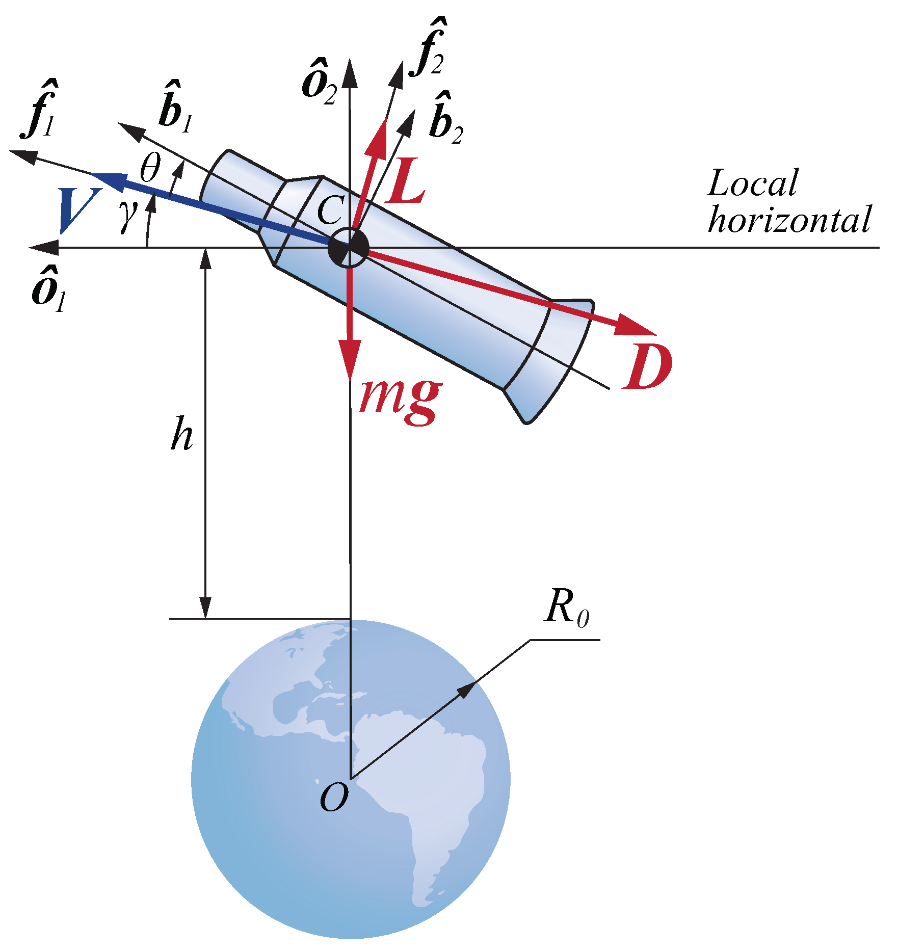
  • The Local Vertical–Local Horizontal (LVLH) frame O is defined through an orthonormal right-hand set of unit vectors o ^ k , k = 1 , 2 , 3 , with an origin at the target’s CoM. The o ^ 2 vector is directed along the local vertical from the center of the Earth to the CoM of the target; the o ^ 1 vector is aligned with the local horizontal (Figure 2).
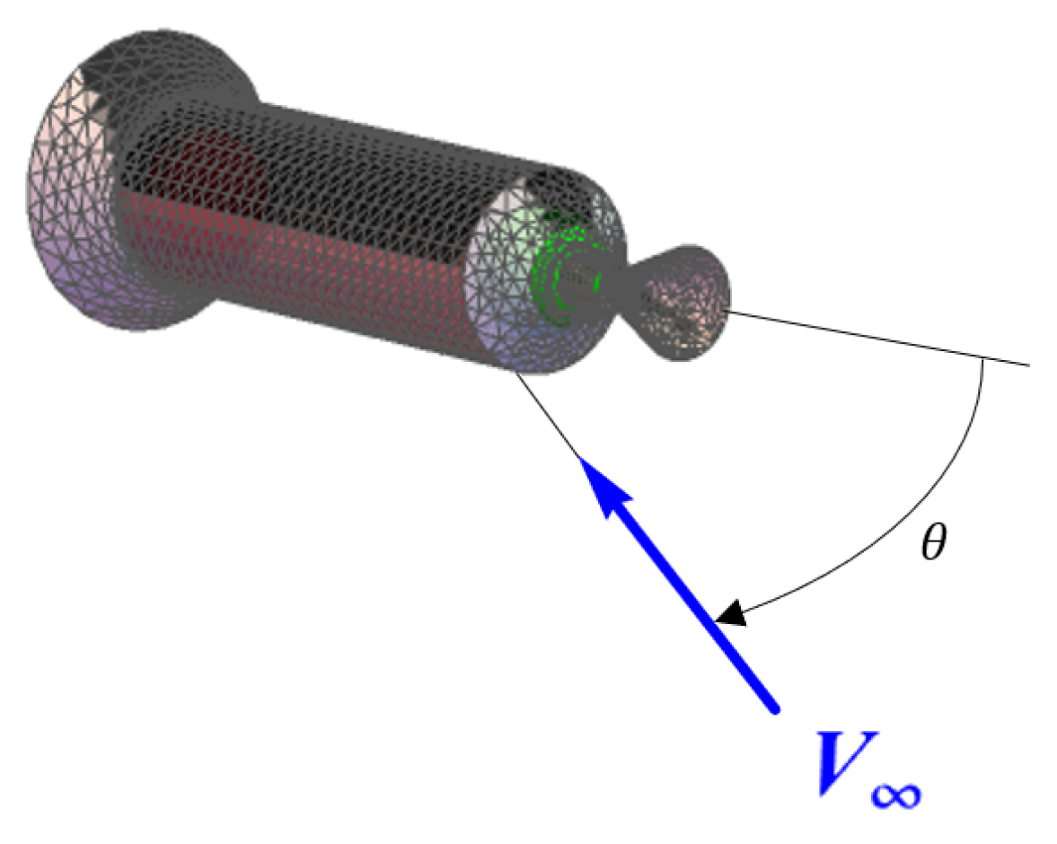
  • The flight path frame F is defined through a set of unit vectors f ^ k with an origin at the CoM, with the f ^ 1 vector coinciding with the velocity V of the CoM. The transformation matrix Φ between O and F is defined by
    v F = Φ v O
    where
    Φ = cos γ sin γ 0 sin γ cos γ 0 0 0 1
    where γ is the flight path angle (Figure 2).
  • The body-fixed frame B is defined through a set b ^ k . These vectors coincide with the target’s principal axes of inertia, and the b ^ 1 vector lies along the longitudinal axis of symmetry. The orientation of b ^ k relative to f ^ k is described by a symmetric ( 1 , 3 , 1 ) set of Euler angles corresponding to three successive positive rotations: first about Axis 1 by the precession angle ψ , then about Axis 3 by the nutation angle θ (angle of attack), 0 < θ < π , and finally, about Axis 1 by the spin angle φ , as shown in Figure 3. The transformation matrix Θ between F and B is defined by
    v B = Θ v F
    where
    Θ = cos θ cos ψ sin θ sin θ sin ψ cos φ sin θ cos θ cos φ cos ψ sin φ sin ψ cos ψ sin φ + cos θ cos φ sin ψ sin θ sin φ cos θ cos ψ sin φ cos φ sin ψ cos φ cos ψ cos θ sin φ sin ψ .
  • The intermediate frames I and I are defined through unit vector sets i ^ k and i ^ k , respectively. The orientations of these frames relative to the orbital frame are determined by the above-mentioned rotations: a single rotation by the angle ψ for the i ^ k frame and two successive rotations by the angles ψ and θ for the i ^ k frame.

3.3. Equations of Motion

3.3.1. Motion of Centre of Mass

The planar motion of the CoM of the target during its descent in the atmosphere is described by the well-known equations
V ˙ = D m g sin γ ,
γ ˙ = L m V cos γ V g V 2 R 0 + h ,
h ˙ = V sin γ
where V is the speed of the CoM, m is the stage’s mass, g = μ / ( R 0 + h ) 2 is the gravitational acceleration, μ and R 0 are the gravitational parameter and the mean radius of the Earth, respectively, h is the orbital altitude, and D is the aerodynamic drag (Figure 2),
D = C D θ , h q A r ,
C D is the drag coefficient, L is the aerodynamic lift,
L = C L θ , h q A r ,
C L is the lift coefficient, A r is the reference area of the target, q = ρ V 2 / 2 is the dynamic pressure, and ρ is the air density.

3.3.2. Attitude Motion
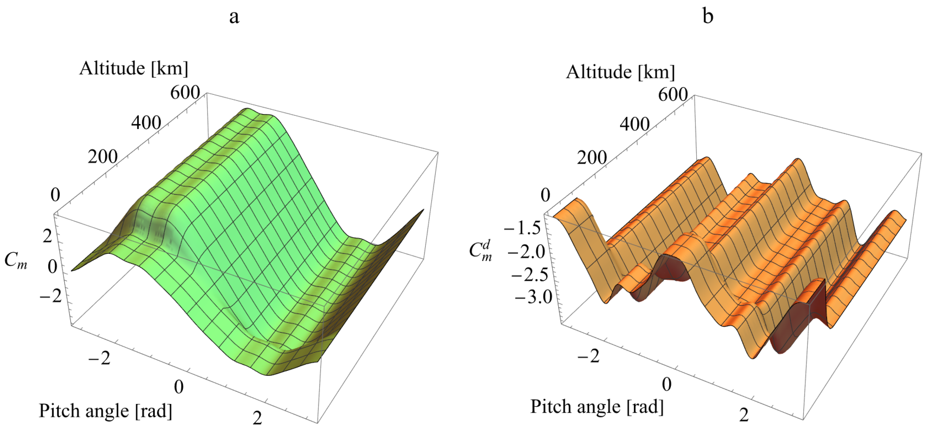
The attitude motion during the descent is governed by nonlinear differential equations ([32], Equations (2.26)–(2.30)) describing the evolution of all three Euler angles chosen in Section 3.2 (Figure 3). However, in the considered case of an axisymmetric body, the equation for the pitch angle is sufficient [32]:
θ ¨ = M θ + M θ d J z G R cos θ R G cos θ sin 3 θ
where J z = J y is the transverse moment of inertia.
The first term on the right-hand side of Equation (10) is due to the aerodynamic torque, which is the sum of the restoring and damping torques. In this paper, the restoring aerodynamic torque M θ ,
M θ = C m θ , h q L r A r ,
is understood as a torque that, for a given altitude and dynamic pressure, depends only on the orientation of the body’s longitudinal axis with respect to the flow vector. For a body of revolution with the CoM on the axis of geometric symmetry, the restoring aerodynamic torque is fully described by the aerodynamic coefficient C m . In Equation (11), L r is the reference length. The pitch damping aerodynamic torque, M θ d , which depends on the pitch rate θ ˙ according to the equation
M θ d = C m d θ , h θ ˙ ρ V 2 L r 2 A r ,
is crucial for modeling the descent into the lower regions of the atmosphere, where the air density becomes significant. In Equation (12), C m d is the damping torque coefficient.
The second term on the right-hand side of Equation (10) is due to the gyroscopic torque. It depends on the quantities R and G, which represent, up to a constant factor, the generalized momenta corresponding to the spin and precession angles, respectively. In the absence of damping, the attitude motion in consideration corresponds to the Lagrange case, for which these quantities are the first integrals of the system. In the presence of the pitch damping, these quantities are known to vary very slowly, so it is still possible to state that they remain constant [32]:
R = J x J z φ ˙ 0 + ψ ˙ 0 cos θ 0 = c o n s t ,
G = R cos θ 0 + ψ ˙ 0 sin 2 θ 0 = c o n s t .
In Equations (13) and (14), J x is the longitudinal moment of inertia, and θ 0 , φ ˙ 0 , and ψ ˙ 0 are the initial conditions of the attitude motion.

3.4. Load Factors

The main cause of the re-entering rocket bodies’ breakup in the atmosphere is the distributed aerodynamic loads. Their intensity can be taken to be proportional to the longitudinal and transverse load factors, which, in their turn, are proportional to the projections of the net aerodynamic force on the b ^ 1 and b ^ 2 axes, respectively. In the general case, these projections depend on the precession angle ψ and the angle of attack θ . For a given angle of attack, both load factors reach their maximum values when the stage’s longitudinal axis lies in the flight path plane, i.e., when sin ψ = 0 . Thus, the maximum longitudinal n x and transverse n y load factors can be written as
n x = 1 m g D cos θ L sin θ ,
n y = 1 m g D sin θ + L cos θ .
The critical values of the load factors, which can be used to estimate the breakup altitude, obviously depend on the launch vehicle. According to Ref. [33], for popular launch vehicles such as the Ariane family, Zenit, or Proton, the critical longitudinal and transverse load factors can be roughly assumed to be equal to 7 and 4, respectively. However, the breakup altitude determination is beyond the scope of the present paper.

4. Case Study of Large Debris Re-Entry

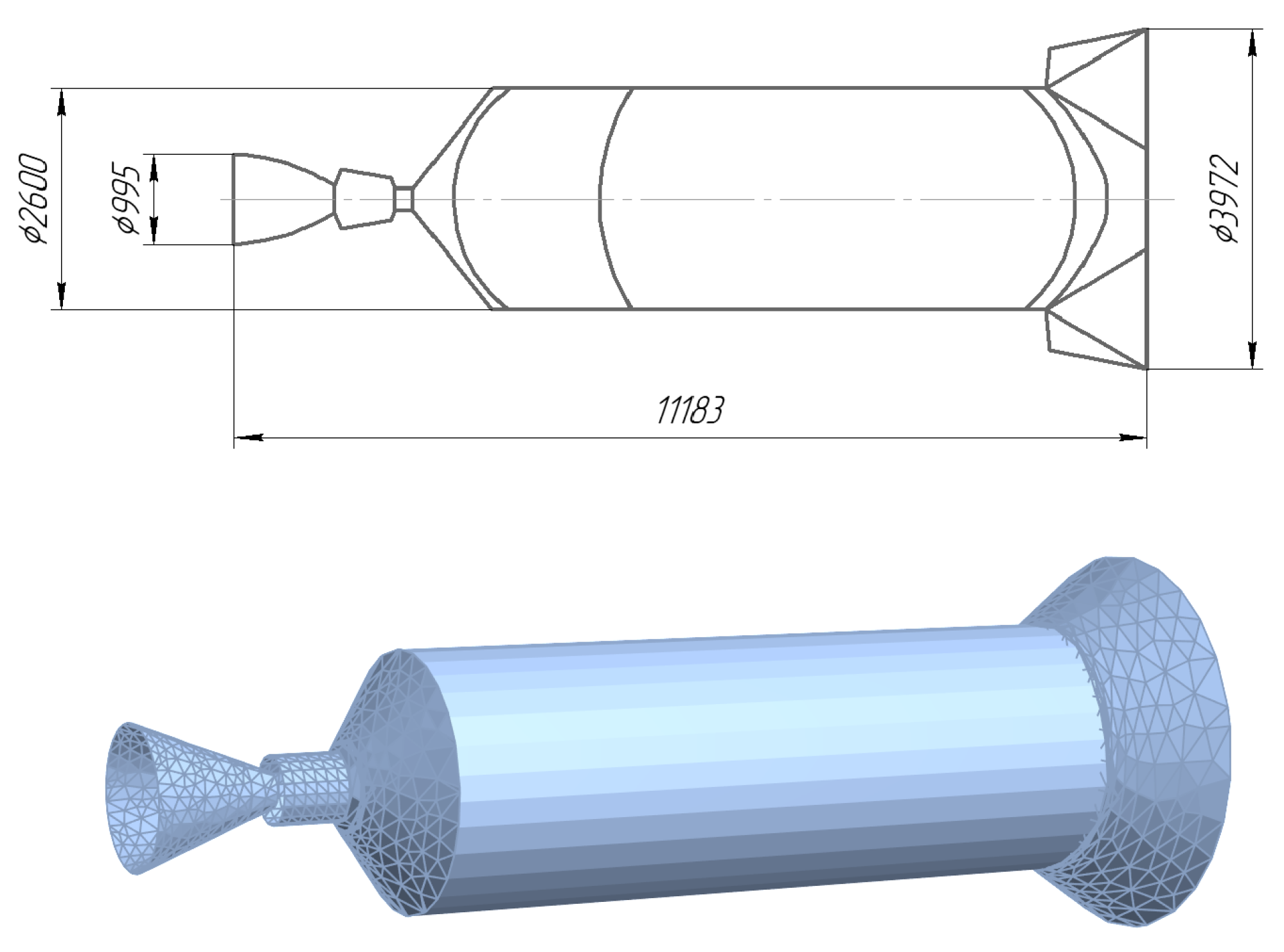
4.1. Target Upper Stage: Ariane 4 H10

The numerical simulations will be performed for the Ariane 4 H10 stage shown in the top part of Figure 4. Further in this paper, we will refer to this rocket body as the example target. Its geometry and mass-inertial characteristics are summarized in Table 1. Figure 4 also depicts a simplified 3D model of the example target that was used to calculate its aerodynamic characteristics.
The aerodynamic torque coefficients are calculated as follows. First, one needs to divide the surface of the target into a number of small flat elements (see Figure 4), then find the pressure and shear stress coefficients c p i and c τ i for each element. Since during the re-entry the altitude of the object changes, to calculate the above-mentioned coefficients, one needs to take into account the changes in the Knusden number K n , which determines the flow regime. When K n is larger than 10, the flow is free molecular, so one can assume that the reflected air molecules’ speed distribution is Maxwellian and use the Schaaf and Chambre’s approach [35]. K n < 0.01 corresponds to the continuum hypersonic regime, where the Newton impact theory [36] is applicable. For the transition regime, when 10 > K n > 0.01 , following Ref. [24], we use the Wilmoth’s bridging law [37]. For the example target, the critical altitudes, corresponding to the values K n = 10 and K n = 0.01 , are approximately 180 km and 100 km, respectively (Figure 5). Once the pressure and shear stress coefficients for each element are calculated, one can obtain the aerodynamic coefficients using well-known summation formulas (see, e.g., Ref. [36]). For example, the restoring aerodynamic torque coefficient is
C m = 1 A r L r i = 1 N A i r i × c p i n ^ i + c τ i τ ^ i · i ^ 3
where r i is the radius-vector from the CoM to the geometric center of the i-th element, τ ^ i is the unit tangential vector of the i-th element, n ^ i is the unit normal vector of the i-th element directed in such a way that n ^ i · V ^ 0 , V ^ = i ^ 3 is the unit vector of the incident stream, A i is the area of the i-th element, and N is the number of elements. Note that it is necessary to exclude from consideration the elements that are shielded by the upstream components of the body. An example of surface meshing with shielding taken into account is shown in Figure 6. The damping torque coefficient is
C m d = C m ω ¯
where ω ¯ = L r V / θ ˙ is the dimensionless pitch rate.
Figure 7 and Figure 8 show the calculated aerodynamic coefficients as functions of the pitch angle and altitude, which are 2 π -periodic in θ . Note that each surface has a pronounced transition region in the range of 100–180 km, i.e., between the continuum and free molecular regimes.

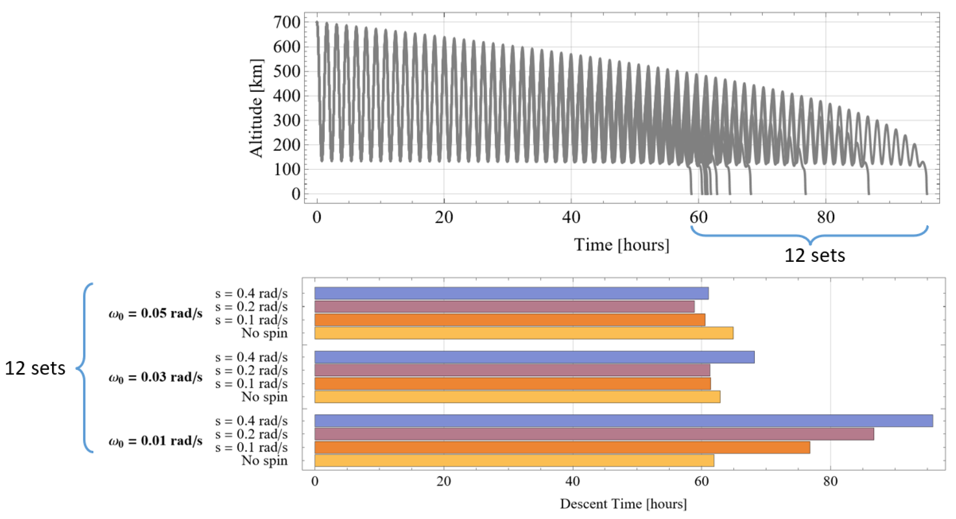
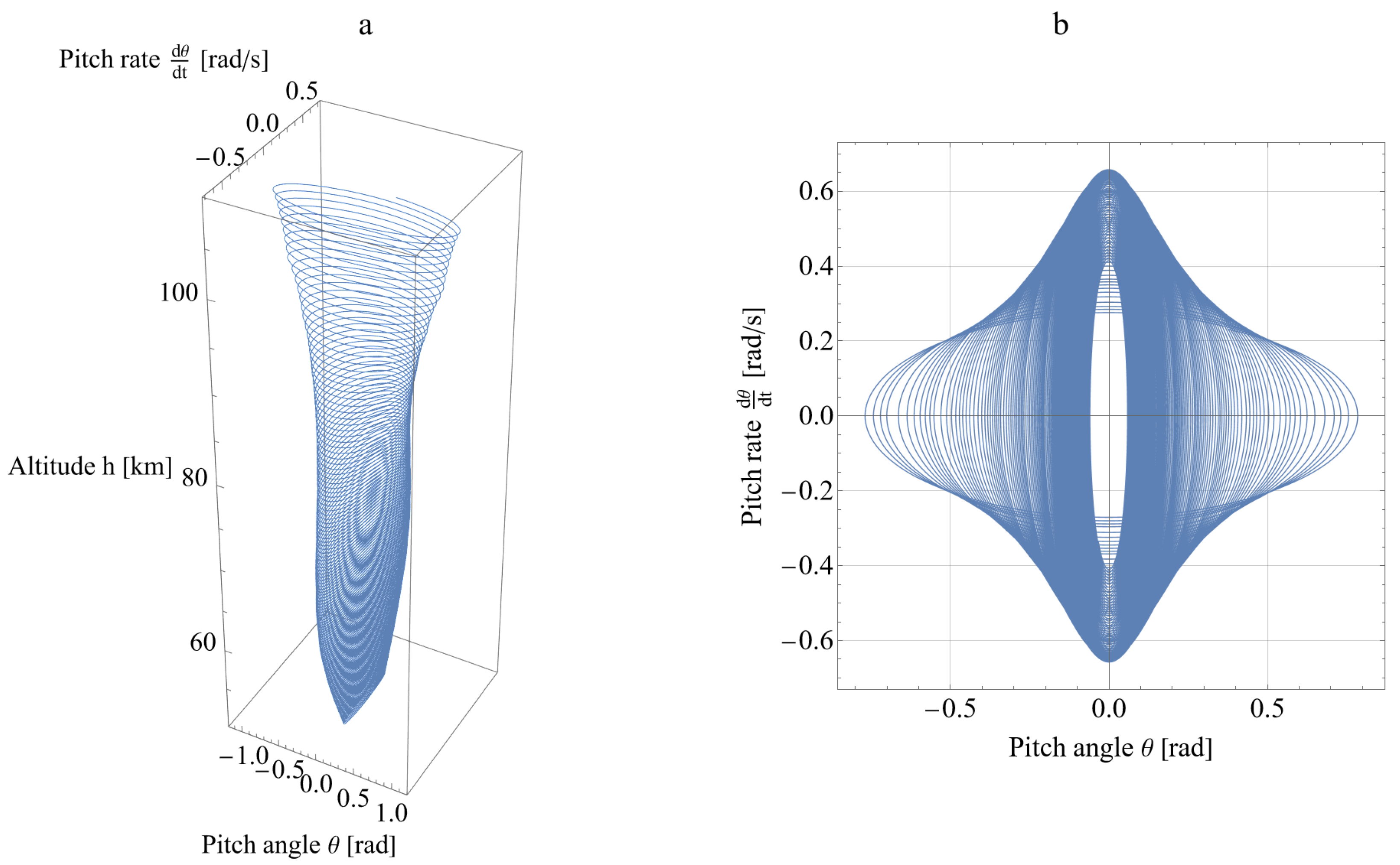
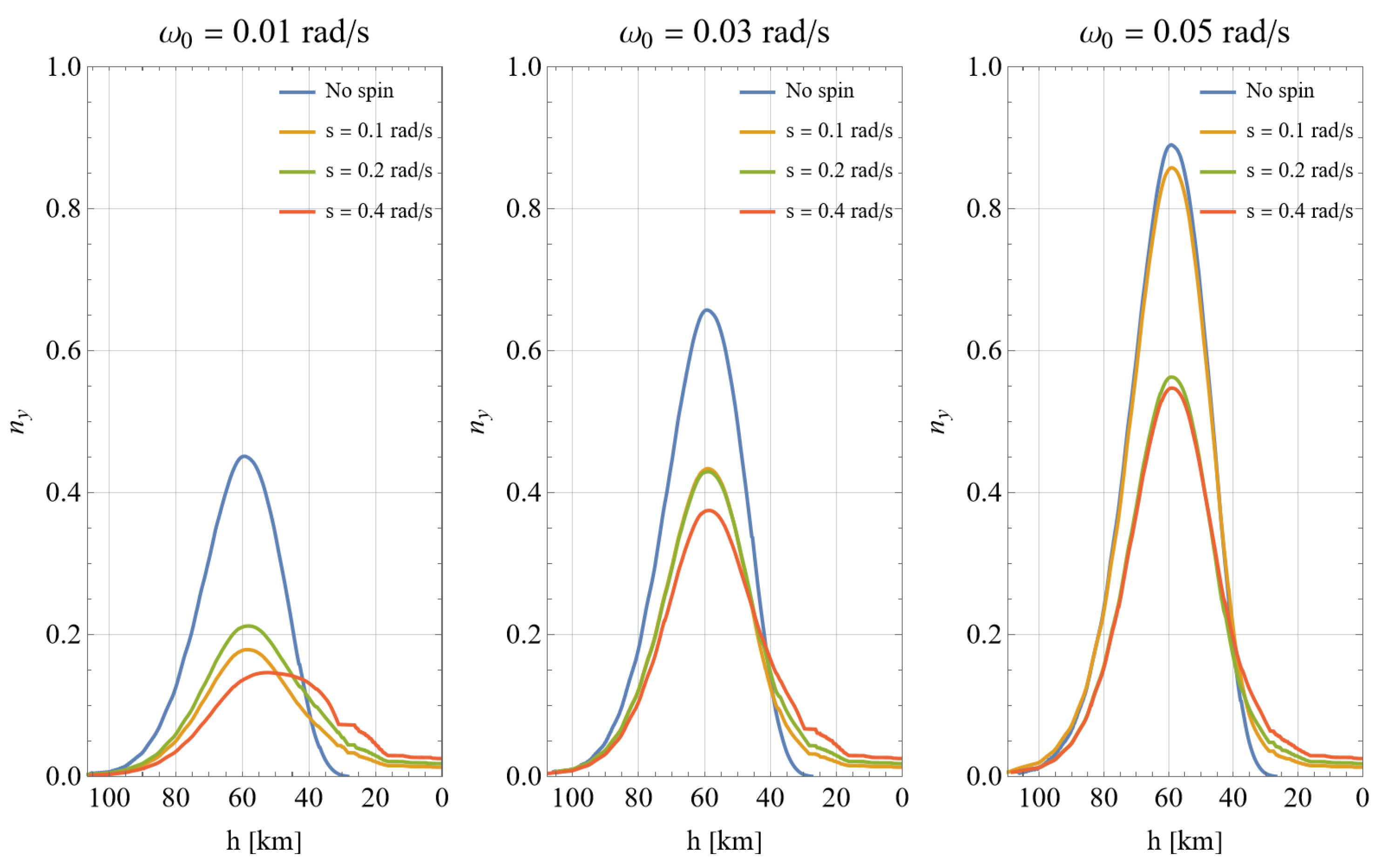
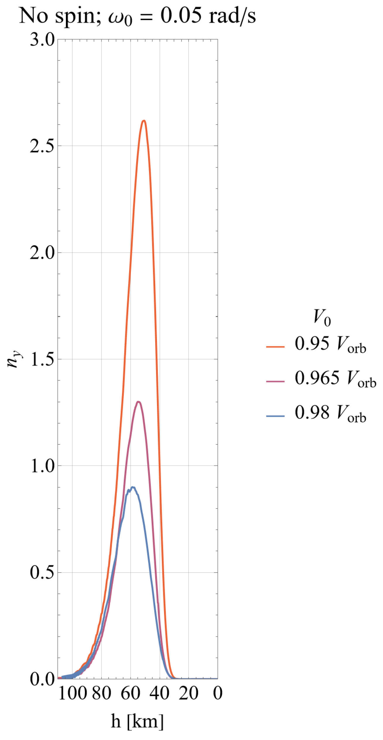
4.2. Numerical Simulations

For the numerical simulations, Equations (5)–(7) and (10) were used. The initial conditions are given in Table 2 and Table 3. In order to investigate the influence of the initial pitch and spin rates on the re-entry process, 12 sets of initial conditions were formed. A quarter of the sets correspond to a pure planar rotation since it is characterized by the absence of the initial spin.
Figure 9 represents the altitude histories and descent times for all 12 sets. It can be seen that, for the example target, the descent takes from 60 to 100 h. The longest descent time corresponds to set #9, which is characterized by the fastest spin rate and the slowest pitch rate.
Two phase trajectories, which are typical for the simulated cases, are shown in Figure 10 (no initial spin: set #4) and Figure 11 (with an initial spin: set #1), with the left part of each figure being a three-dimensional phase diagram of the motion. Unlike the classical 2D phase trajectories given on the right, the 3D diagrams allow the evolution of the pitch angle and its rate with the orbital altitude to be seen. Each 3D diagram shows that, due to the increasing atmospheric density, the target goes from a regime “high amplitude–low angular speed” to a regime “low amplitude–high angular speed”. After the target passes the altitude of about 60 km, both phase variables start to decrease due to the increasing influence of the damping torque. It is also worth mentioning that Figure 11 demonstrates the typical behavior of a spinning target: the gyroscopic torque does not let the pitch angle become zero or less than zero, so the phase trajectory is asymmetric as it cannot cross the imaginary “wall” shown in red.
Figure 12 and Figure 13 depict the re-entry diagrams where different descent parameters are plotted versus the altitude. Here again, the first diagram illustrates the case where there is no initial spin (set #4), and the second corresponds to a spinning target (set #1). It can be seen that despite the fact that the speed V monotonically decreases, the dynamic pressure q has a peak since it depends not only on the speed but also on the air density.
However, in light of the paper’s aim, the most interesting peaks are the ones that occur in the n y and n x curves, as they determine the maximum structural loads on the rocket body. Taking into account the high importance of the load factors, it is reasonable to plot their evolution for all 12 simulated cases. As can be seen from Figure 14, all the n x curves almost coincide, so the longitudinal load factor does not substantially depend on the initial conditions of the attitude motion during descent. This is due to a high value of the aerodynamic damping coefficient for this particular body, making the pitch angle small. In addition, for the example target, the lift coefficient is about 10 times smaller than the drag coefficient. In the virtue of Equation (15), all this makes the drag dominant in the longitudinal load factor.
Figure 15, showing the transverse load factor curves, reflects the main point of the present study. It can be seen that, unlike n x , the transverse load factor n y is highly sensitive to the initial conditions of the attitude motion during descent. Namely, a high initial pitch rate and low initial spin rate both lead to a high transverse load factor, while a low initial pitch rate and high initial spin rate result in low values of n y .
It should be mentioned that, of course, there exists a way to obtain even higher load factors than those that are shown at the right-most part of Figure 15, namely, to make the descent trajectory steeper by giving the target higher negative delta-v. Figure 16 shows that, e.g., for the set #4, a 3% change in the initial speed results in a three times higher n y . Such measures surely have to be discussed during any removal mission design; however, they are beyond the scope of the present paper, which focuses on the attitude motion.

5. Discussion: Using Features of Attitude Motion for Load Factor Regulation

In the previous section, it was demonstrated that changing the initial state of the free descent allows regulation of the structural load on the target during its descent. For a spent upper stages removal, both low and high load factors can be beneficial and can form the basis of two possible mission scenarios.

5.1. Mission Scenarios Exploiting Benefits of Low and High Load Factors

Low values of the transverse load factor delay the stage breakup and, thus, are useful for missions where there is a need to minimize the debris footprint size. Such a scenario is possible if the amplitude of the angle of attack during re-entry is close to zero. It is shown above that, to achieve this, the stage must start its free descent with a high initial spin rate and no tumbling.
High values of the transverse load factor provoke the rocket body’s breakup at relatively high altitudes and, thus, are needed for missions aimed at ensuring that the fragments produced by the breakup do not reach the Earth’s surface. In this case, conversely, the amplitude of the angle of attack must be as high as possible. This will happen if, initially, the stage is in the state of planar tumbling with no spin.

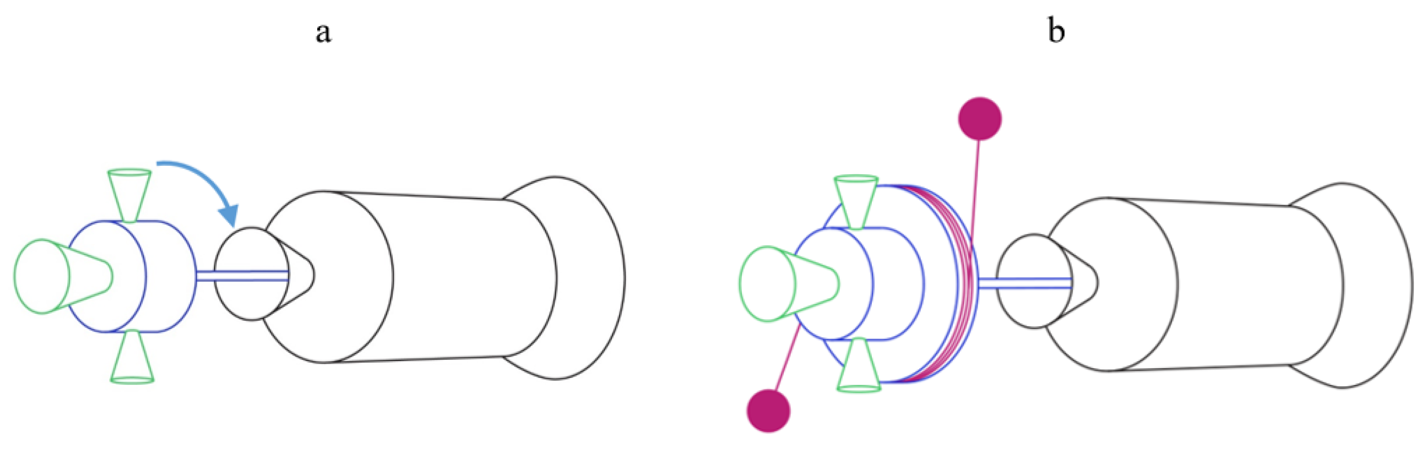
5.2. Possible De-Orbiting Devices

The two scenarios discussed above require two de-orbiting devices (Figure 17) having some common features and some differences to be discussed in this section.
Since both of the above scenarios imply that the rocket body and the de-orbiting device maintain a reliable contact needed to change the initial attitude motion state of the target, the devices must be equipped with a nozzle docking system, different possible implementations of which are given, e.g., in Refs. [19,20,21]. Another common feature of the devices is the thrusters needed to achieve the desired delta-v and initial tumbling state.
The difference between the two devices stems from the fact that the low load factor scenario requires a fast initial spin, while the second one, conversely, needs a complete de-spin of the target. To control the spin, we propose to utilize popular methods based on the usage of the internal forces, keeping the net angular momentum constant: a fast spin can be achieved with a gyrostat-type device (Figure 17a) equipped with a motor intended to rotate the shaft that is fixed at the target’s nozzle, thus affecting the spin rate of the target, and the de-spin can be performed by a Yo-Yo mechanism [38] (Figure 17b).

6. Conclusions

This paper deals with the active removal of spent upper stages using de-orbiting devices not only to ensure its fast re-entry, but also to regulate the aerodynamic loads on it during its free descent in the atmosphere. The key ideas of the study can be summarized as follows.
  • Depending on the initial conditions of the descent, the character of the attitude motion can be different. Precessional motion or planar tumbling are the alternatives.
  • The character of the attitude motion and its initial conditions determine the aerodynamic load factors and, thus, the breakup altitude.
  • The required initial conditions can be provided by de-orbiting devices, which should be able to control both the tumbling and the spin of the target.
Future development of the study will include the target breakup altitude determination, the consideration of the thermal loads acting during the descent, and the investigation of the effects of possible dynamic/aerodynamic asymmetry of the target.

Author Contributions

Conceptualisation: V.S.A. and D.A.S.; investigation: V.S.A. and D.A.S.; methodology: V.S.A. and D.A.S.; software and simulations: D.A.S.; writing—original draft: D.A.S.; writing—review and editing: V.S.A. and D.A.S. All authors have read and agreed to the published version of the manuscript.

Funding

This research received no external funding.

Institutional Review Board Statement

Not applicable.

Data Availability Statement

Data are contained within the article.

Conflicts of Interest

The authors declare no conflicts of interest.

References

  1. Wright, E.; Boley, A.; Byers, M. Improving casualty risk estimates for uncontrolled rocket body reentries. J. Space Saf. Eng. 2024, 11, 74–79. [Google Scholar] [CrossRef]
  2. Pardini, C.; Anselmo, L. Uncontrolled re-entries of spacecraft and rocket bodies: A statistical overview over the last decade. J. Space Saf. Eng. 2019, 6, 30–47. [Google Scholar] [CrossRef]
  3. Salmaso, F.; Trisolini, M.; Colombo, C. A Machine Learning and Feature Engineering Approach for the Prediction of the Uncontrolled Re-Entry of Space Objects. Aerospace 2023, 10, 297. [Google Scholar] [CrossRef]
  4. Ledkov, A.; Aslanov, V. Review of contact and contactless active space debris removal approaches. Prog. Aerosp. Sci. 2022, 134, 100858. [Google Scholar] [CrossRef]
  5. Ledkov, A.; Aslanov, V. Evolution of space tethered system’s orbit during space debris towing taking into account the atmosphere influence. Nonlinear Dyn. 2019, 96, 2211–2223. [Google Scholar] [CrossRef]
  6. Aslanov, V.S.; Sizov, D.A. A spent upper stage removal mission aimed to reduce debris impact footprint size. Acta Astronaut. 2020, 168, 23–30. [Google Scholar] [CrossRef]
  7. Endo, Y.; Kojima, H.; Trivailo, P.M. New formulation for evaluating status of space debris capture using tether-net. Adv. Space Res. 2022, 70, 2976–3002. [Google Scholar] [CrossRef]
  8. Aslanov, V.S.; Ledkov, A.S. Survey of tether system technology for space debris removal missions. J. Spacecr. Rocket. 2023, 60, 1355–1371. [Google Scholar] [CrossRef]
  9. Bourabah, D.; Gnam, C.; Botta, E.M. Inertia tensor estimation of tethered debris through tether tracking. Acta Astronaut. 2023, 212, 643–653. [Google Scholar] [CrossRef]
  10. Boonrath, A.; Botta, E.M. Validation of Models for Net Deployment and Capture Simulation with Experimental Data. J. Spacecr. Rocket. 2024, 61, 181–199. [Google Scholar] [CrossRef]
  11. Couzin, P.; Teti, F.; Rembala, R. Active removal of large debris: System approach of deorbiting concepts and technological issues. In Proceedings of the 6th European Conference on Space Debris, Darmstadt, Germany, 22–25 April 2013. [Google Scholar]
  12. Sizov, D.A.; Aslanov, V.S. Space debris removal with harpoon assistance: Choice of parameters and optimization. J. Guid. Control Dyn. 2020, 44, 767–778. [Google Scholar] [CrossRef]
  13. Mao, L.; Zhao, W.; Pang, Z.; Gao, J.; Du, Z. Study On The Penetration Characteristics of Conical Harpoon on Rotating Space debris. Adv. Space Res. 2024, 74, 4109–4122. [Google Scholar] [CrossRef]
  14. Wu, C.; Yue, S.; Shi, W.; Gao, J.; Du, Z.; Zhao, Z.; Liu, Z. Research on adaptive penetration characteristics of space harpoon based on aluminum honeycomb buffer. Adv. Space Res. 2024. [Google Scholar] [CrossRef]
  15. Bylard, A.; MacPherson, R.; Hockman, B.; Cutkosky, M.R.; Pavone, M. Robust capture and deorbit of rocket body debris using controllable dry adhesion. In Proceedings of the 2017 IEEE Aerospace Conference, Big Sky, MT, USA, 4–11 March 2017; IEEE: Piscataway, NJ, USA, 2017; pp. 1–9. [Google Scholar]
  16. Felicetti, L.; Sabatini, M.; Pisculli, A.; Gasbarri, P.; Palmerini, G.B. Adaptive thrust vector control during on-orbit servicing. In Proceedings of the AIAA SPACE 2014 Conference and Exposition, San Diego, CA, USA, 10–12 September 2014; p. 4341. [Google Scholar]
  17. Zhang, Z.; Li, X.; Wang, X.; Zhou, X.; An, J.; Li, Y. TDE-Based Adaptive Integral Sliding Mode Control of Space Manipulator for Space-Debris Active Removal. Aerospace 2022, 9, 105. [Google Scholar] [CrossRef]
  18. Palma, P.; Seweryn, K.; Rybus, T. Impedance Control Using Selected Compliant Prismatic Joint in a Free-Floating Space Manipulator. Aerospace 2022, 9, 406. [Google Scholar] [CrossRef]
  19. Aslanov, V.S.; Yudintsev, V.V. Docking of a space tug with upper stage debris object using deployable flexible beam. In Proceedings of the International Astronautical Congress, Adelaide, Australia, 25–29 September 2017. [Google Scholar]
  20. Kaiser, C.; Sjöberg, F.; Delcura, J.M.; Eilertsen, B. SMART-OLEV—An orbital life extension vehicle for servicing commercial spacecrafts in GEO. Acta Astronaut. 2008, 63, 400–410. [Google Scholar] [CrossRef]
  21. DeLuca, L.T.; Lavagna, M.; Maggi, F.; Tadini, P.; Pardini, C.; Anselmo, L.; Grassi, M.; Tancredi, U.; Francesconi, A.; Pavarin, D.; et al. Large debris removal mission in LEO based on hybrid propulsion. Aerotec. Missili Spaz. 2014, 93, 51–58. [Google Scholar] [CrossRef]
  22. Takahashi, Y.; Nakasato, R.; Oshima, N. Analysis of radio frequency blackout for a blunt-body capsule in atmospheric reentry missions. Aerospace 2016, 3, 2. [Google Scholar] [CrossRef]
  23. Zuppardi, G.; Savino, R.; Mongelluzzo, G. Aero-thermo-dynamic analysis of a low ballistic coefficient deployable capsule in Earth re-entry. Acta Astronaut. 2016, 127, 593–602. [Google Scholar] [CrossRef]
  24. Carná, S.R.; Bevilacqua, R. High fidelity model for the atmospheric re-entry of CubeSats equipped with the drag de-orbit device. Acta Astronaut. 2019, 156, 134–156. [Google Scholar] [CrossRef]
  25. Otsu, H. Aerodynamic Characteristics of Re-Entry Capsules with Hyperbolic Contours. Aerospace 2021, 8, 287. [Google Scholar] [CrossRef]
  26. D’Amato, E.; Notaro, I.; Panico, G.; Blasi, L.; Mattei, M.; Nocerino, A. Trajectory Planning and Tracking for a Re-Entry Capsule with a Deployable Aero-Brake. Aerospace 2022, 9, 841. [Google Scholar] [CrossRef]
  27. Sun, J.; Zhu, H.; Xu, D.; Cai, G. Aerodynamic Thermal Simulation and Heat Flux Distribution Study of Mechanical Expansion Reentry Vehicle. Aerospace 2023, 10, 310. [Google Scholar] [CrossRef]
  28. Otsu, H.; Nagasawa, M.; Tsujimoto, R.; Oshio, Y. Numerical Investigation of Aerodynamic Characteristics of a Re-entry Capsule with Hyperbolic Contours. J. Evol. Space Act. 2023, 1, 64. [Google Scholar]
  29. Peri, L.N.P.; Ingenito, A.; Teofilatto, P. Large-Eddy Simulations of a Hypersonic Re-Entry Capsule Coupled with the Supersonic Disk-Gap-Band Parachute. Aerospace 2024, 11, 94. [Google Scholar] [CrossRef]
  30. Hild, F.; Traub, C.; Pfeiffer, M.; Beyer, J.; Fasoulas, S. Optimisation of satellite geometries in Very Low Earth Orbits for drag minimisation and lifetime extension. Acta Astronaut. 2022, 201, 340–352. [Google Scholar] [CrossRef]
  31. US Standard Atmosphere; National Oceanic and Atmospheric Administration: Washington, DC, USA, 1976.
  32. Aslanov, V.S. Rigid Body Dynamics for Space Applications; Butterworth-Heinemann: Oxford, UK, 2017. [Google Scholar]
  33. Kortman, M.; Ruhl, S.; Weise, J.; Kreisel, J.; Schervan, T.; Schmidt, H.; Dafnis, A. Building block based iBoss approach: Fully modular systems with standard interface to enhance future satellites. In Proceedings of the 66th International Astronautical Congress (Jerusalem), Jerusalem, Israel, 12–16 October 2015; Volume 2, pp. 1–11. [Google Scholar]
  34. Gómez, N.O.; Walker, S.J. Eddy currents applied to de-tumbling of space debris: Analysis and validation of approximate proposed methods. Acta Astronaut. 2015, 114, 34–53. [Google Scholar] [CrossRef]
  35. Schaaf, S.; Chambre, P. Flow of Rarefied Gases, High Speed Aerodynamics and Jet Propulsion. In Fundamentals of Gas Dynamics; Princeton University Press NY: Princeton, NJ, USA, 1958; Volume 3. [Google Scholar]
  36. Gallais, P. Atmospheric Re-Entry Vehicle Mechanics; Springer Science & Business Media: Berlin/Heidelberg, Germany, 2007. [Google Scholar]
  37. Wilmoth, R.G.; Mitcheltree, R.A.; Moss, J.N. Low-density aerodynamics of the stardust sample return capsule. J. Spacecr. Rocket. 1999, 36, 436–441. [Google Scholar] [CrossRef]
  38. Yudintsev, V.; Aslanov, V. Detumbling space debris using modified yo-yo mechanism. J. Guid. Control Dyn. 2017, 40, 714–721. [Google Scholar] [CrossRef]
Figure 1. Spent upper stage removal process.
Aerospace 11 00786 g001
Figure 2. Orbital, flight path, and body-fixed coordinate frames.
Aerospace 11 00786 g002
Figure 3. Euler angles determining the orientation of the body frame relative to the flight path frame.
Aerospace 11 00786 g003
Figure 4. Ariane H10 upper stage (adapted from [34]) and its 3D model used for calculating the aerodynamic coefficients.
Aerospace 11 00786 g004
Figure 5. Knudsen number for a characteristic length of L r = 11.183 m.
Aerospace 11 00786 g005
Figure 6. Ariane 4 H10 model meshing and shielding.
Aerospace 11 00786 g006
Figure 7. Drag (a) and lift (b) coefficients of the example target.
Aerospace 11 00786 g007
Figure 8. Restoring (a) and damping (b) aerodynamic torque coefficients of the example target.
Aerospace 11 00786 g008
Figure 9. Altitude histories and descent times.
Aerospace 11 00786 g009
Figure 10. Phase trajectories (no initial spin: set #4): (a) 3D, (b) 2D.
Aerospace 11 00786 g010
Figure 11. Phase trajectories (with an initial spin: set #1): (a) 3D, (b) 2D.
Aerospace 11 00786 g011
Figure 12. Descent parameters’ evolution (no initial spin: set #4).
Aerospace 11 00786 g012
Figure 13. Descent parameters’ evolution (with an initial spin: set #1).
Aerospace 11 00786 g013
Figure 14. Evolution of the longitudinal load factors for all 12 simulated cases.
Aerospace 11 00786 g014
Figure 15. Evolution of the transverse load factors.
Aerospace 11 00786 g015
Figure 16. Effect of varying delta-v on the evolution of the transverse load factor.
Aerospace 11 00786 g016
Figure 17. Concepts of de-orbiting devices: (a) gyrostat-based, (b) equipped with a Yo-Yo mechanism.
Aerospace 11 00786 g017
Table 1. Parameters of the example target: Ariane 4 H10 [34].
ParameterValue
Mass m2154 kg
Total length = reference length L r 11.183 m
Fuel tank diameter d2.6 m
Reference area A r = π d 2 / 4 5.31  m 2
Longitudinal moment of inertia J x 3000 kg · m 2
Transverse moments of inertia J y = J z 28,000 kg · m 2
Longitudinal shift of the CoM from the nozzle edge 4.0  m
Table 2. Initial conditions. Angles and angular rates are given in radians and radians per second, respectively.
Parameter h 0 [km] V 0 [m/s] γ 0 ψ 0 θ 0 φ 0 ψ ˙ 0 θ ˙ 0 φ ˙ 0
Value700 0.98 V o r b h = h 0 000.100variable (see Table 3)
Table 3. Initial rates [rad/s].
Set #Pitch Rate θ ˙ 0 = ω 0 Spin Rate φ ˙ 0 = s
10.050.4
20.2
30.1
40
50.030.4
60.2
70.1
80
90.010.4
100.2
110.1
120
Disclaimer/Publisher’s Note: The statements, opinions and data contained in all publications are solely those of the individual author(s) and contributor(s) and not of MDPI and/or the editor(s). MDPI and/or the editor(s) disclaim responsibility for any injury to people or property resulting from any ideas, methods, instructions or products referred to in the content.

