Article

Demonstration of Polyethylene Nitrous Oxide Catalytic Decomposition Hybrid Thruster with Dual-Catalyst Bed Preheated by Hydrogen Peroxide

1
Department of Aerospace Engineering, Korea Advanced Institute of Science and Technology (KAIST), 291, Daehak-ro, Yuseong-gu, Daejeon 34141, Republic of Korea
2
Department of Bioenvironmental Energy, Pusan National University, 1268-50, Samnangjin-ro, Samnangjin-eup, Miryang-si 50463, Gyeongsangnam-do, Republic of Korea
*
Authors to whom correspondence should be addressed.
Current address: Space Pioneer Program Office, Korea Aerospace Research Institute (KARI), 169-84, Gwahak-ro, Yuseong-gu, Daejeon 34133, Republic of Korea.
Aerospace 2025, 12(2), 158; https://doi.org/10.3390/aerospace12020158
Submission received: 26 December 2024 / Revised: 10 February 2025 / Accepted: 17 February 2025 / Published: 18 February 2025
(This article belongs to the Special Issue Green Propellants for In-Space Propulsion)

Abstract

:
Although various studies on nitrous oxide as a prospective green propellant have been recently explored, a polyethylene nitrous oxide catalytic decomposition hybrid thruster was barely demonstrated due to an inordinately high catalyst preheating time of a heater, which led to the destruction of components. Therefore, hydrogen peroxide was used as a preheatant, a substance to preheat, with a dual-catalyst bed. The thruster with polyethylene (PE) as a fuel, N2O as an oxidizer, H2O2 as the preheatant, Ru/Al2O3 as a catalyst for the oxidizer, and Pt/Al2O3 as a catalyst for the preheatant was arranged. A preheatant supply time of 10 s with a maximum catalyst bed temperature of more than 500 °C and without combustion and an oxidizer supply time of 20 s with a burning time of approximately 15 s were decided. Because the catalyst bed upstream part for decomposing the preheatant was far from the post-combustion chamber, the post-combustion chamber pressure increased and the preheatant mass flow rate decreased after a hard start during the preheatant supply time. Moreover, because the catalyst bed upstream part primarily contributed to preheating, the maximum catalyst bed temperature was less than the decomposition temperature of the preheatant during the preheatant supply time. Additionally, because the catalyst bed downstream part for decomposing the oxidizer was far from the post-combustion chamber, the post-combustion chamber pressure decreased and then increased during a transient state in the oxidizer supply time.

1. Introduction

Nitrous oxide is a promising green propellant that has advantages such as low toxicity, a moderate specific impulse, high applicability, self-pressurization, and catalytic decomposition as well as disadvantages such as the necessity to preheat a catalyst [1,2,3]. Recently, thrusters with nitrous oxide as a monopropellant and an oxidizer of a bipropellant have been investigated worldwide. For example, Giuseppe Gallo et al. [4,5] experimentally investigated N2O decomposition with a Pd/Al2O3 cylindrical pellet catalyst and predicted the fuel regression rate in an HDPE single-port hybrid rocket fed by liquid nitrous oxide, Ryota Okuda et al. [6] investigated the fuel regression characteristics of an axial-injection end-burning hybrid rocket using nitrous oxide, Jincheol Kim et al. [7] studied the endurance and performance of an impregnated ruthenium catalyst for a thruster system, Vadim Zakirov et al. [8] investigated a model for the operation of nitrous oxide monopropellant, Raffaele D’Elia et al. [9] experimentally analyzed SiC-based refractory concrete in hybrid rocket nozzles, and Shinichiro Tokudome et al. [10] experimentally studied a nitrous oxide/ethanol (NOEL) propulsion system. However, a polyethylene nitrous oxide catalytic decomposition hybrid thruster was scarcely demonstrated, though the catalytic decomposition for a hybrid thruster was proposed by Eun Sang Jung et al. [11] who investigated autoignitable and restartable hybrid rockets using catalytic decomposition of an oxidizer, and a counterflow burner rather than the hybrid thruster was demonstrated by Coit T. Hendley, IV et al. [12] who investigated catalytic decomposition of nitrous oxide for use in hybrid rocket motors. As shown in Figure 1, a major problem in the demonstration of the polyethylene nitrous oxide catalytic decomposition hybrid thruster with a heater for preheating the catalyst is that melted PE blocked a catalyst bed void, distributor holes, and a fuel port because of an excessively high catalyst preheating time. In order to settle the problem, a method for preheating the catalyst with a low catalyst preheating time is required. Meanwhile, the catalytic decomposition of H2O2 was introduced to preheat the catalyst by Doyun Lee et al. [13], who investigated a high-performance microthruster with ammonium-dinitramide-based monopropellant. Furthermore, a dual-catalyst bed with two different catalysts was introduced to reduce the pressure drop across a catalyst bed by Seonuk Heo et al. [14], who investigated the effect of a dual-catalytic bed using two different catalyst sizes for hydrogen peroxide thruster. Because of its low-temperature startability, it is feasible to use H2O2 with an additional catalyst as a “preheatant”, which is defined as a substance to preheat. Hence, in this research, a polyethylene nitrous oxide catalytic decomposition hybrid thruster with a dual-catalyst bed preheated by hydrogen peroxide was demonstrated as a novel solution to mitigate the problem concerning the failure of components caused by the heater.

2. Materials and Methods

Based on Reference [15], the thruster, catalysts, and an experimental setup of the polyethylene nitrous oxide catalytic decomposition hybrid thruster with the dual-catalyst bed preheated by hydrogen peroxide were designed, and differences in details are described as follows:
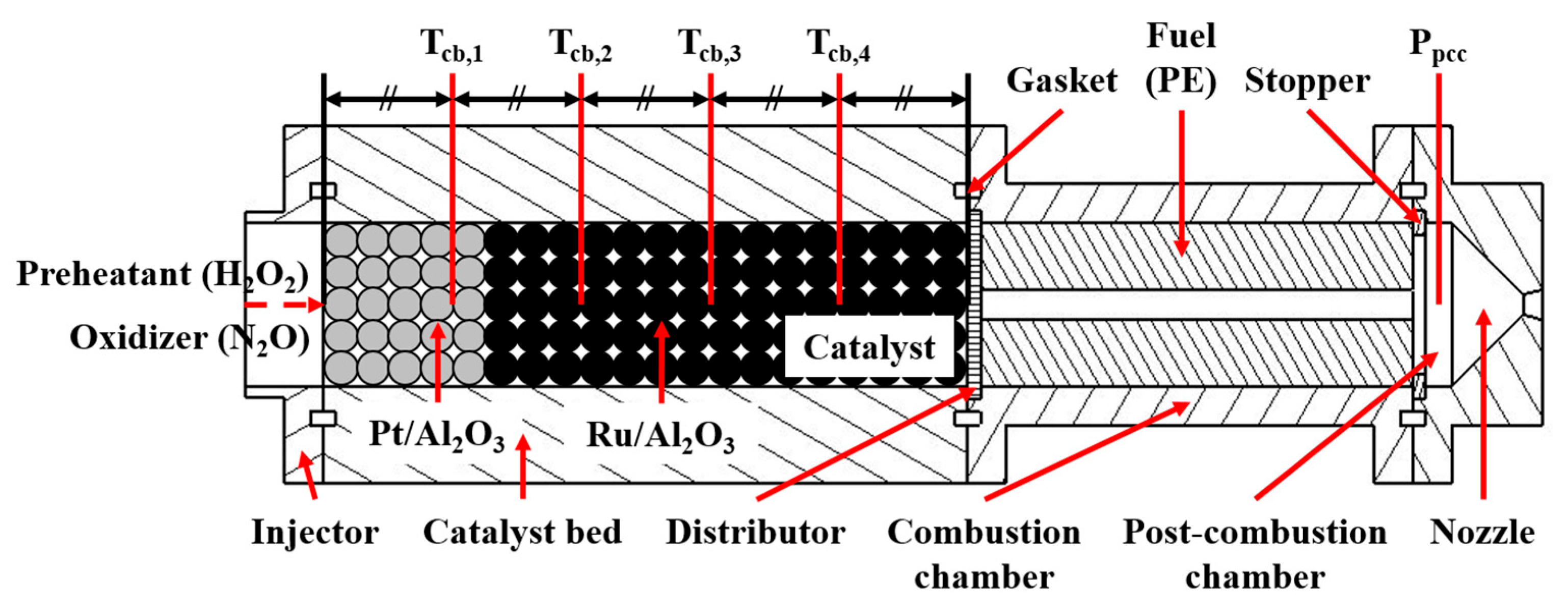
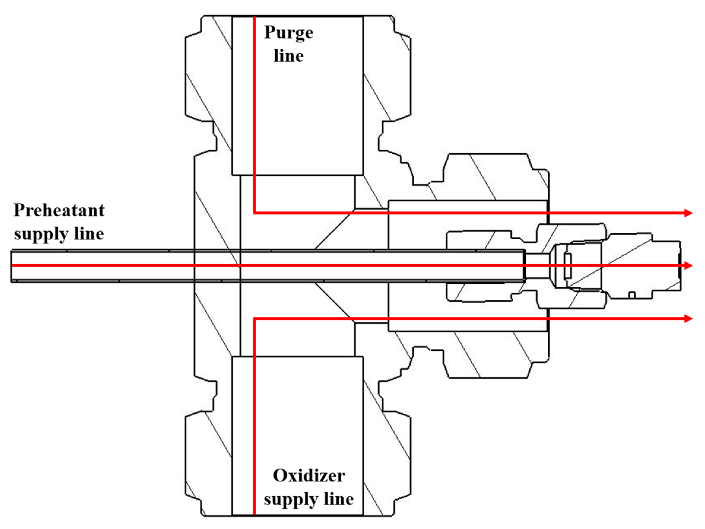
As shown in Equations (1) and (2), Table 1, and Figure 2, the thruster was designed. PE, N2O (Shincheon Total Gas Co., (Daejeon, Republic of Korea)), and H2O2 were chosen as the fuel, the oxidizer, and the preheatant. A catalyst bed diameter and a combustion chamber diameter were established as an MFC fitting diameter. The catalyst bed length was established as a value suitable for the experimental setup. The fuel port quantity was established as a minimum to exclude a multiport. A pressure sensor of a pressure transducer with an accuracy of ±0.15% was positioned at the post-combustion chamber. Temperature sensors of thermocouples (Hankook Electric Heater (Daejeon, Republic of Korea), Type K thermocouple) with an accuracy of ±0.19% were positioned at points of 20, 40, 60, and 80 mm from the front of the catalyst bed. As shown in Figure 3, an injector manifold was devised to harmonize an oxidizer supply line, a preheatant supply line, and a purge line. A spray nozzle (Spraying Systems Co., (Glendale Heights, IL, USA), B1/8HH-316SS1) was employed to supply the preheatant.
Z c b , p h = m p h ˙ / V c b , p h ,   V c b , p h = ( π D c b 2 / 4 ) L c b , p h ,   L D c b , p h = L c b , p h / D c b
D c c = D p o , f u + 2 r f u ˙ ¯ t b
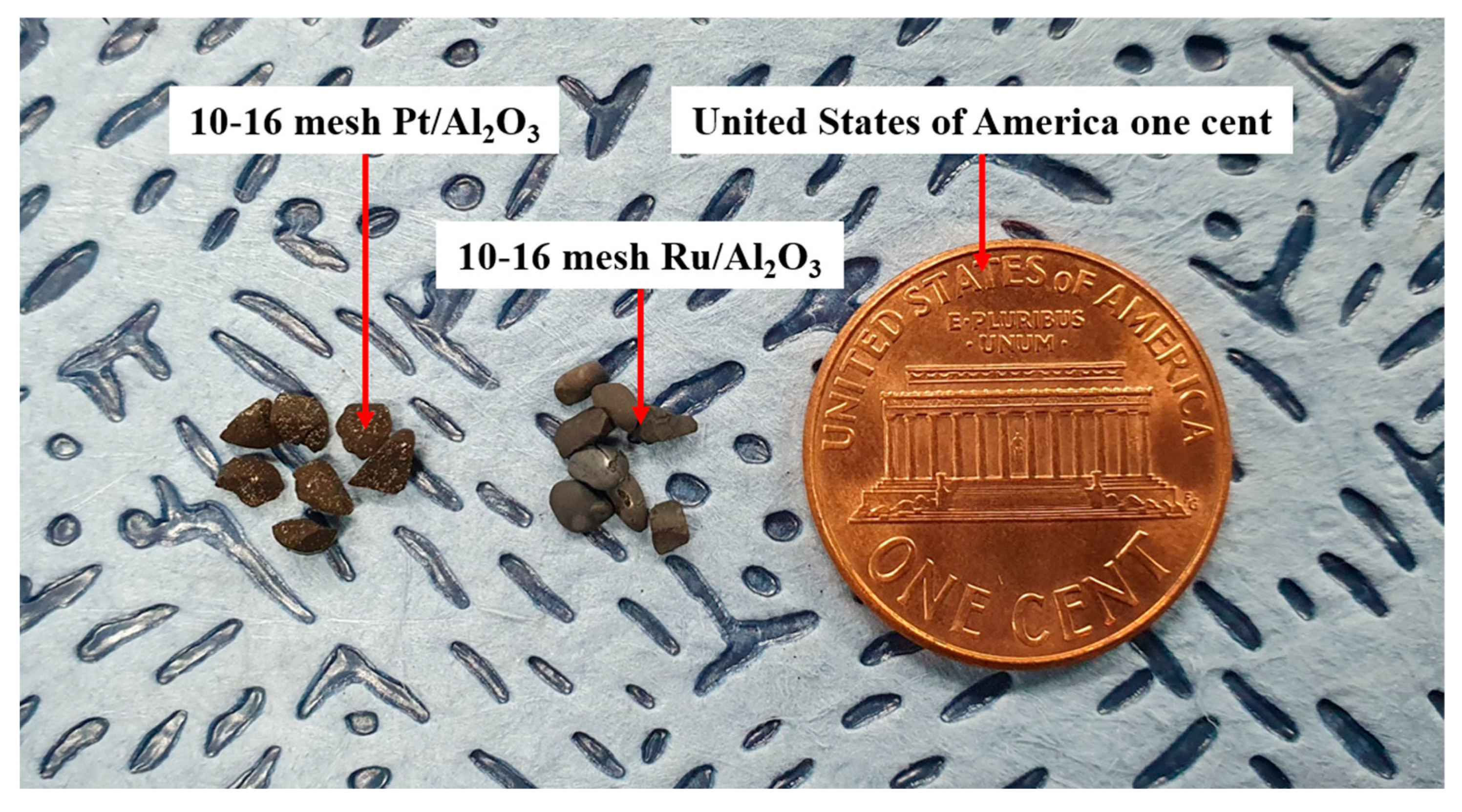
As shown in Table 2 and Figure 4, catalysts were categorized into Pt/Al2O3 for the preheatant and Ru/Al2O3 for the oxidizer and were composed of Pt and Ru as active materials and Al2O3 as a support. H2PtCl6·6H2O (HanTech PMC Co., Ltd. (Anyang-si, Gyeonggi-do, Republic of Korea)) and RuCl3·3H2O (HanTech PMC Co., Ltd.) were employed as active material precursors. In the fabrication by impregnation, rinsing was replaced with a reduction with a mixture (H2 4 vol.% + N2 96 vol.% (Shincheon Total Gas Co.)) and the furnace (500 °C, 5 h).
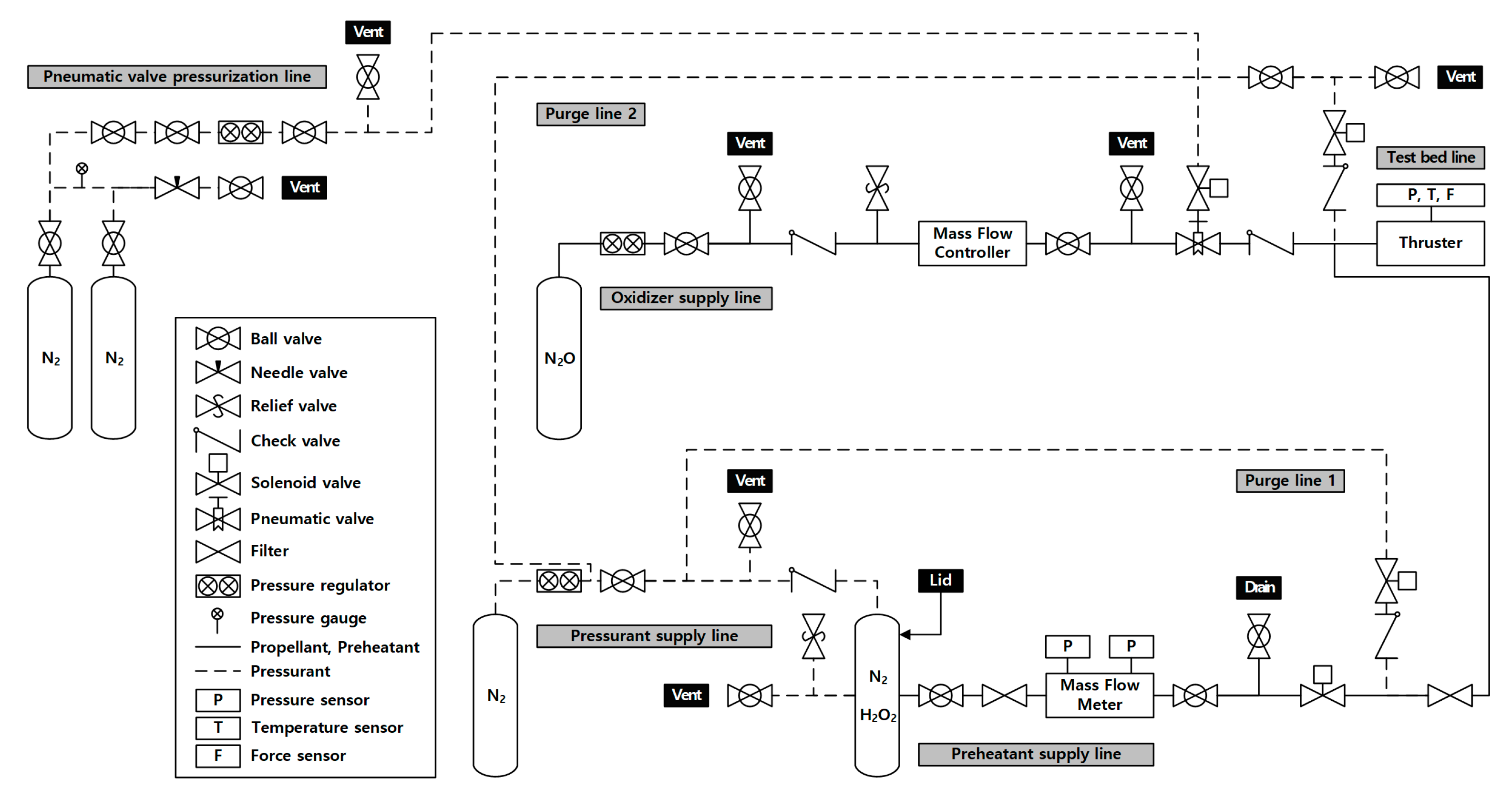
As shown in Figure 5, the experimental setup was designed. N2 was chosen as a pressurant. MFC (Teledyne Hastings Instruments (Hampton, VA, USA), HFC-D-307B) with an accuracy of ±0.20% was employed to control an oxidizer mass flow rate, PLC to activate solenoid valves, and DAQ to measure pressures with a rate of 1000 Hz and temperatures with a rate of 80 Hz.
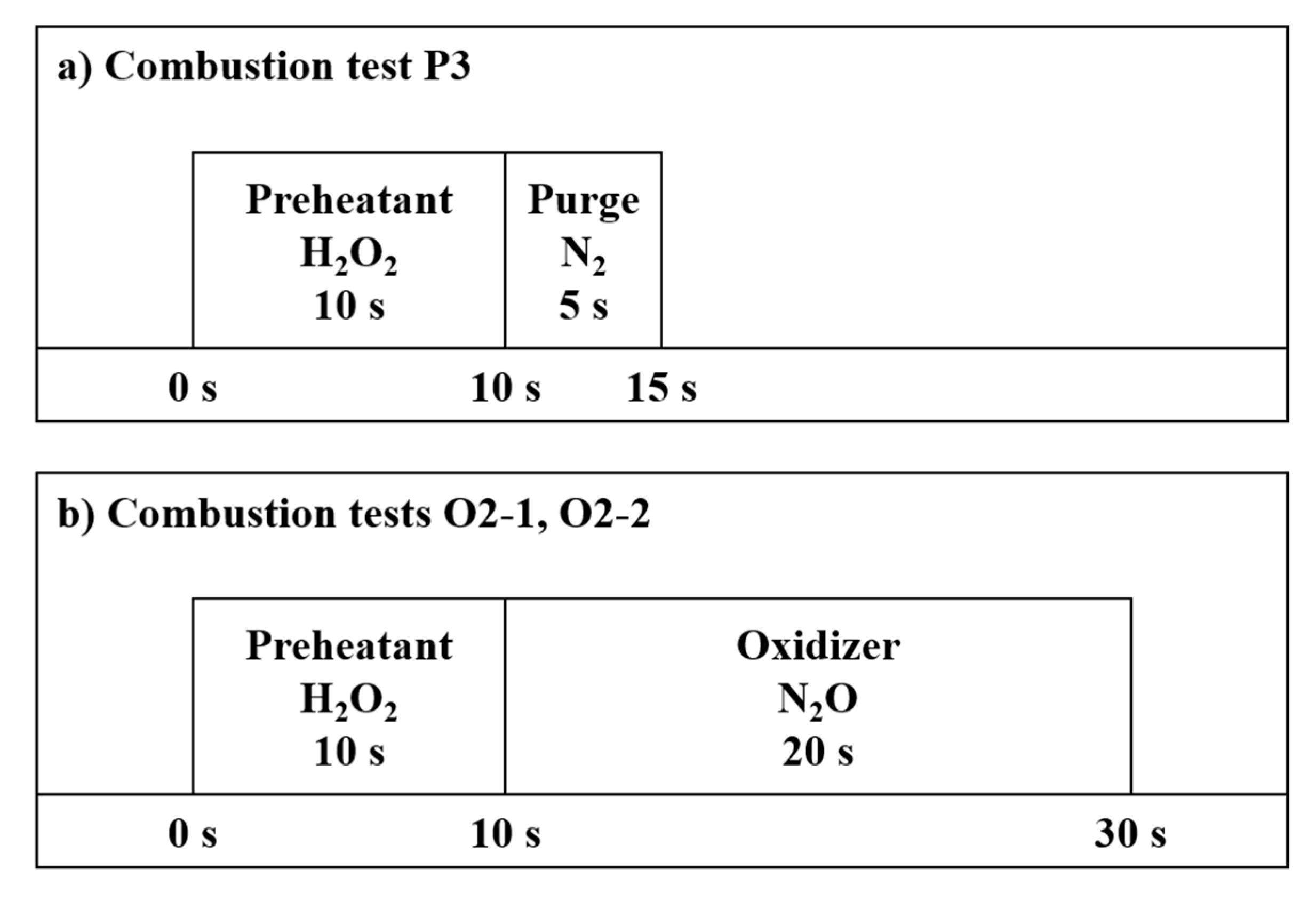
Before a combustion test, a real propellant test for the preheatant was implemented to assess the discharge coefficient of MFM and inspect the spray nozzle. As shown in Table 3 and Figure 6, six combustion tests were implemented with a preheatant mass flow rate of approximately 5 g/s by measuring the MFM upstream pressure, the MFM downstream pressure, the post-combustion chamber pressure, four catalyst bed temperatures, and the oxidizer mass flow rate. Catalysts were replaced with new ones after each combustion test to avoid deactivation. In order to establish a preheatant supply time such that the maximum catalyst bed temperature is more than 500 °C and combustion does not occur, combustion tests P1 through P3 were conducted by increasing the preheatant supply time. In order to establish an oxidizer supply time such that the burning time is approximately 15 s, combustion tests O1 through O2-2 were conducted by increasing the oxidizer supply time. Combustion tests O2-1 and O2-2 were replicates under the final test condition for assessing repeatability.

3. Results and Discussion

As shown in Equations (3)–(5) and Table 4 and Table 5, the thruster with appropriate preheatant and oxidizer supply times was successfully demonstrated in combustion tests. Preheatant mass flow rates were computed by MFM. Combustions during the preheatant supply time were not confirmed. This is because flames were not observed during the preheatant supply time of every combustion test and the fuel masses before and after combustion tests P1 through P3 were not changed. Post-combustion chamber pressure fluctuations were computed by Equation (3). Since every post-combustion chamber pressure fluctuation was below 0.10, every post-combustion chamber pressure was stable. Oxidizer mass flow rates were computed by MFC. Average fuel regression rates were computed by Equation (4) with a fuel density [16]. Characteristic velocity efficiencies were computed by Equation (5) with post-combustion chamber pressures as combustion chamber pressures. Since every characteristic velocity efficiency was above 0.80, every combustion was complete. In combustion test P3, the preheatant supply time of 10 s was decided to achieve the maximum catalyst bed temperature of more than 500 °C and no combustion. In combustion tests O2-1 and O2-2, the oxidizer supply time of 20 s was decided to achieve the burning time of around 15 s.
Y P c c , p o s t = ( P c c , p o s t , m a x P c c , p o s t , m i n ) / P c c , p o s t ¯
m f u ˙ t b = N p o , f u ρ f u ( π ( ( D p o , f u + 2 r f u ˙ ¯ t b ) 2 D p o , f u 2 ) / 4 ) L p o , f u
η C = C e x p / C t h e = ( P c c A n t / m p r ˙ ) / C , A n t = π D n t 2 / 4
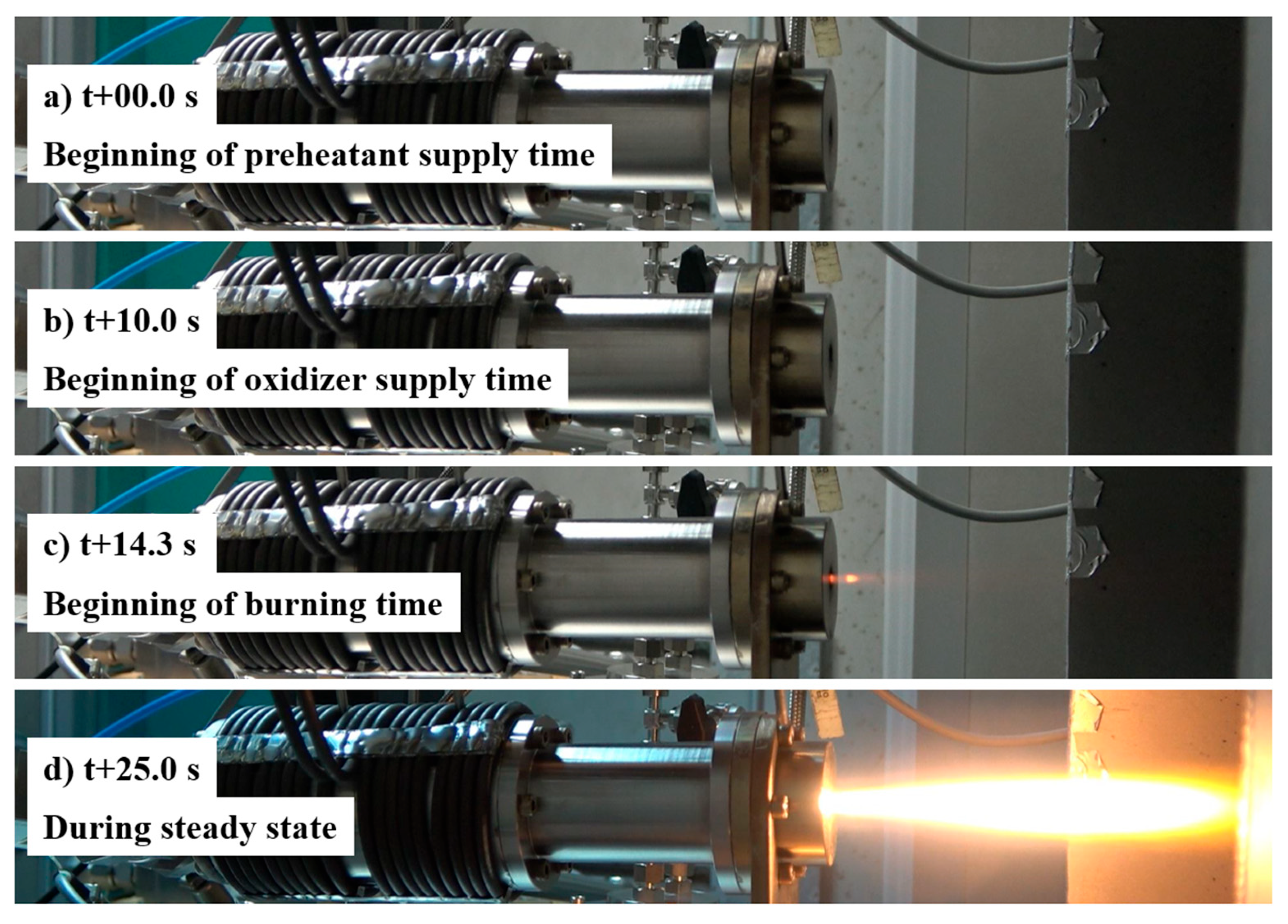
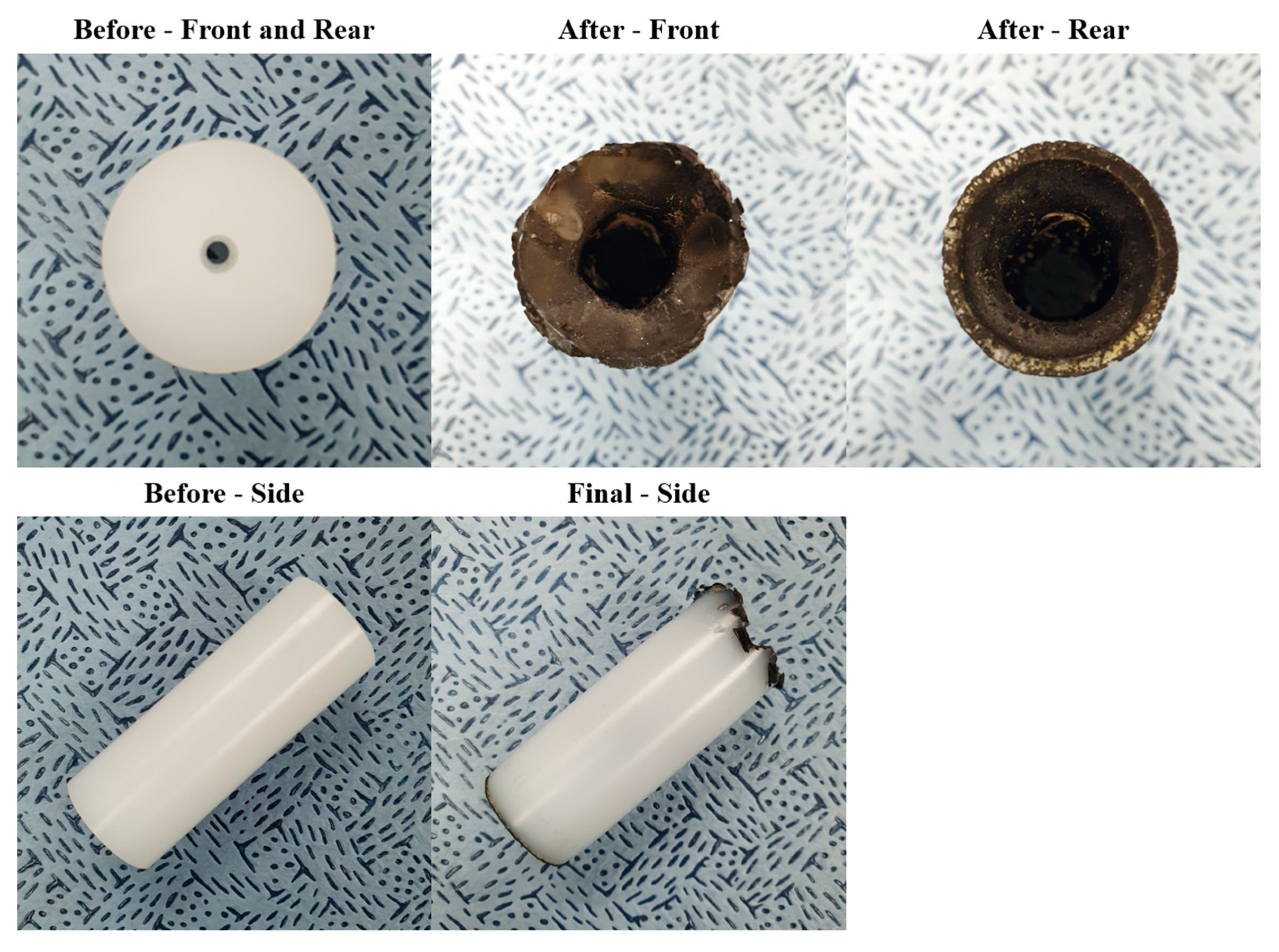
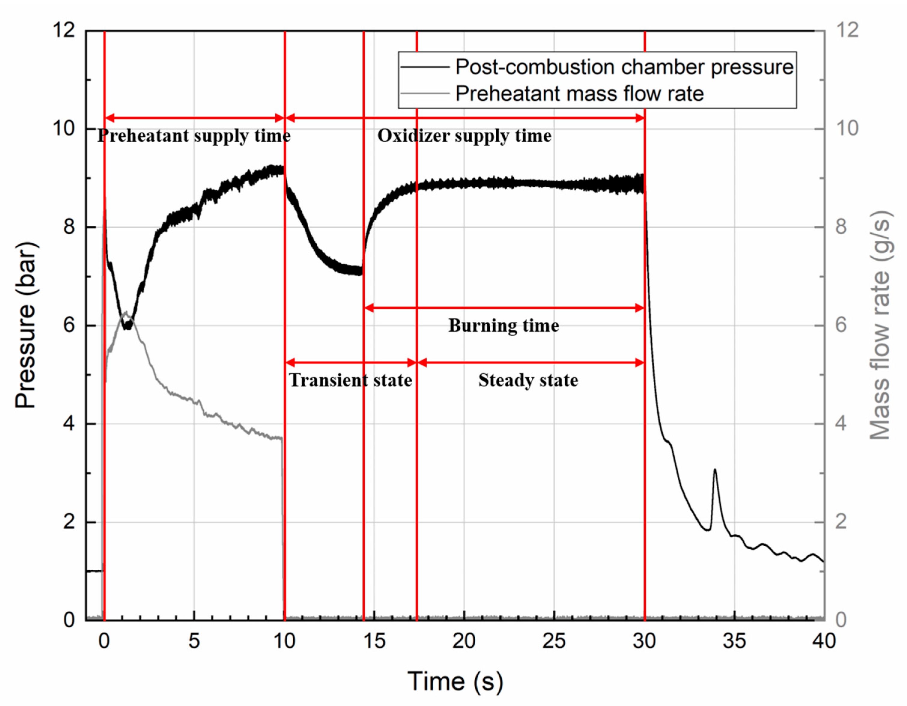
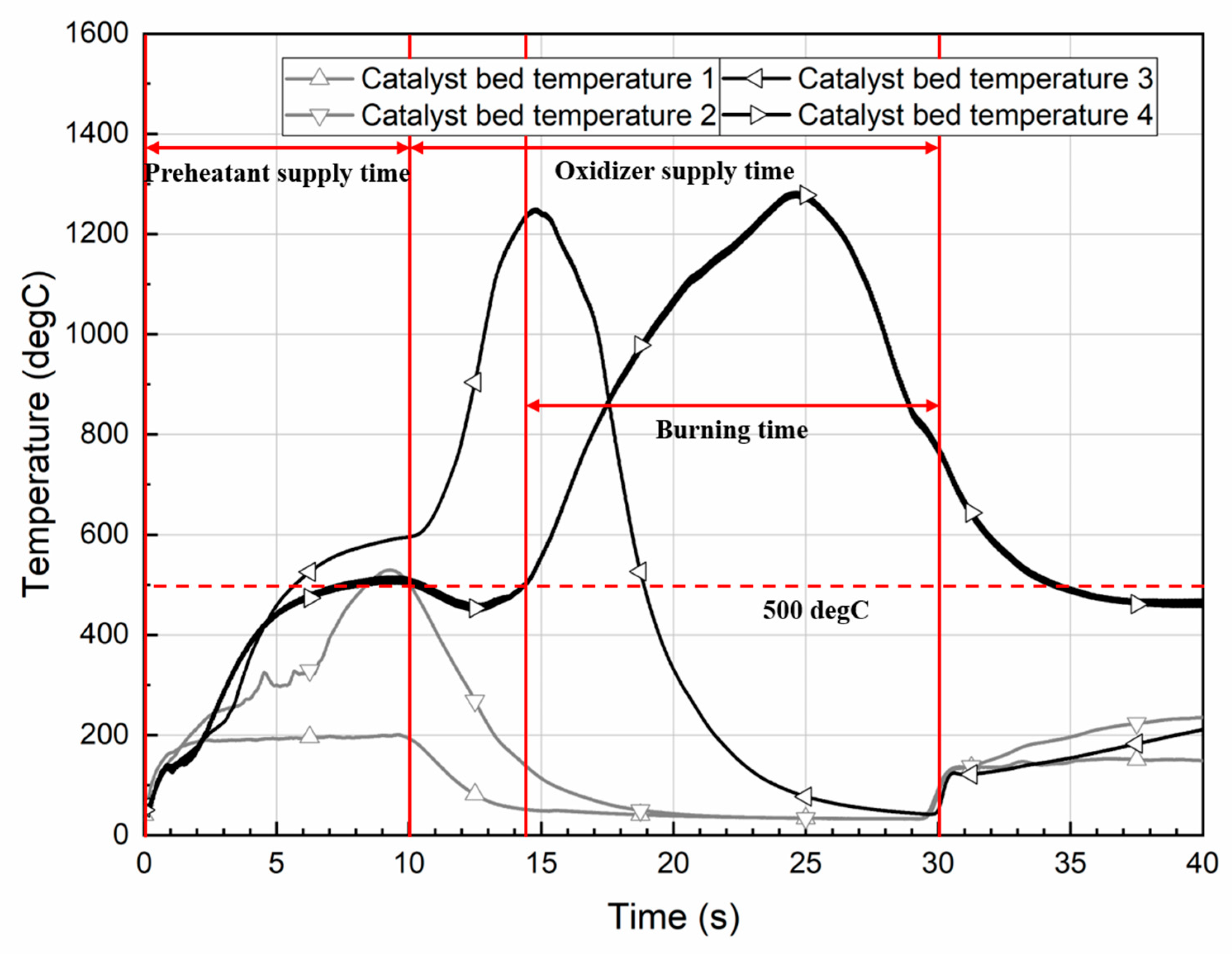
Combustion test O2-1 was chosen as an example because combustion tests O1 through O2-2 had a resemblance. As shown in Figure 7, the flame was observed during the oxidizer supply time, not the preheatant supply time. As shown in Figure 8, the decrease in fuel port length was negligible. As shown in Figure 9 and Figure 10, there were three phenomena. First, during the preheatant supply time, the post-combustion chamber pressure increased and the preheatant mass flow rate decreased after a hard start. This is because the catalyst bed upstream part for decomposing the preheatant and the post-combustion chamber were far apart. Second, during the preheatant supply time, the maximum catalyst bed temperature was less than the decomposition temperature of the preheatant of approximately 741 °C [17,18]. This is because the catalyst bed upstream part, not the downstream part for decomposing the oxidizer, primarily participated in the preheating of the catalyst bed. Third, during a transient state in the oxidizer supply time, the post-combustion chamber pressure decreased and then increased. This is because the catalyst bed downstream part and the post-combustion chamber were far apart.

4. Conclusions

A dual-catalyst bed preheated by hydrogen peroxide was applied to demonstrate the polyethylene nitrous oxide catalytic decomposition hybrid thruster. In the case of PE as the fuel, N2O as the oxidizer, H2O2 as the preheatant, Ru/Al2O3 as the catalyst for the oxidizer, Pt/Al2O3 as the catalyst for the preheatant, 10 s as the preheatant supply time, and 20 s as the oxidizer supply time, the thruster was satisfactorily demonstrated with the maximum catalyst bed temperature during the preheatant supply time of more than 500 °C, no combustion during the preheatant supply time, and the burning time of approximately 15 s. An increase in the post-combustion chamber pressure and a decrease in the preheatant mass flow rate after the hard start during the preheatant supply time were due to a high distance between the catalyst bed upstream part and the post-combustion chamber. The maximum catalyst bed temperature during the preheatant supply time being less than the decomposition temperature of the preheatant was due to the low participation of the catalyst bed downstream part in the preheating of the catalyst bed. An increase after a decrease in the post-combustion chamber pressure during the transient state in the oxidizer supply time was due to a high distance between the catalyst bed downstream part and the post-combustion chamber. For future research, an improvement of the thruster by supplementing a pre-combustion chamber and a scale effect, both of which are absent in the current design, is planned. The pre-combustion chamber and the scale effect were studied in References [19,20,21] and References [22,23,24,25,26,27], respectively.

Author Contributions

Conceptualization, methodology, software, validation, formal analysis, resources, data curation, writing—original draft preparation, visualization, S.L.; investigation, S.L., V.M.P.U. and E.J.; writing—review and editing, V.M.P.U. and E.J.; supervision, project administration, funding acquisition, S.K. All authors have read and agreed to the published version of the manuscript.

Funding

This research was funded by Poongsan-KAIST (Korea Advanced Institute of Science and Technology) Future Technology Research Center, grant number PSRD-2023-0002RC. The APC was funded by Eunsang Jung.

Data Availability Statement

The original contributions presented in this study are included in the article. Further inquiries can be directed to the corresponding authors.

Conflicts of Interest

The authors declare no conflicts of interest. The funders had no role in the design of the study; in the collection, analyses, or interpretation of data; in the writing of the manuscript; or in the decision to publish the results.

Abbreviations

The following abbreviations are used in this manuscript:
DAQData Acquisition
HDPEHigh-Density Polyethylene
MFCMass Flow Controller
MFMMass Flow Meter
PEPolyethylene
PLCProgrammable Logic Controller

Nomenclature

The following nomenclature is used in this manuscript:
A area
C characteristic velocity
D diameter
L length
L D length to diameter ratio
m ˙ mass flow rate
N quantity
P pressure
r ˙ regression rate
t b burning time
V volume
Y fluctuation
Z decomposition capacity
η efficiency
ρ density
Superscript
¯ average
Subscript
c b catalyst bed
c c combustion chamber
e x p experimental
f u fuel
m a x maximum
m i n minimum
n t nozzle throat
p h preheatant
p o port
p o s t post
t h e theoretical

References

  1. Sutton, G.P.; Biblarz, O. Rocket Propulsion Elements, 9th ed.; John Wiley & Sons, Inc.: Hoboken, NJ, USA, 2017. [Google Scholar]
  2. Zakirov, V.; Sweeting, M.; Lawrence, T.; Sellers, J. Nitrous Oxide as a Rocket Propellant. Acta Astronaut. 2001, 48, 353–362. [Google Scholar] [CrossRef]
  3. Nosseir, A.E.S.; Cervone, A.; Pasini, A. Review of State-of-the-Art Green Monopropellants: For Propulsion Systems Analysts and Designers. Aerospace 2021, 8, 20. [Google Scholar] [CrossRef]
  4. Gallo, G.; Di Martino, G.D.; Festa, G.; Savino, R. Experimental Investigation of N2O Decomposition with Pd/Al2O3 Cylindrical Pellets Catalyst. J. Spacecr. Rocket. 2020, 57, 720–727. [Google Scholar] [CrossRef]
  5. Gallo, G.; Kamps, L.; Hirai, S.; Carmicino, C.; Harunori, N. Prediction of the fuel regression-rate in a HDPE single port hybrid rocket fed by liquid nitrous oxide. Combust. Flame 2024, 259, 113160. [Google Scholar] [CrossRef]
  6. Okuda, R.; Komizu, K.; Tsuji, A.; Miwa, T.; Fukada, M.; Yokobori, S.; Soeda, K.; Kamps, L.; Nagata, H. Fuel Regression Characteristics of Axial-Injection End-Burning Hybrid Rocket Using Nitrous Oxide. J. Propuls. Power 2022, 38, 759–770. [Google Scholar] [CrossRef]
  7. Kim, J.; Kim, T. Study on Endurance and Performance of Impregnated Ruthenium Catalyst for Thruster System. J. Nanosci. Nanotechnol. 2018, 18, 1263–1265. [Google Scholar] [CrossRef] [PubMed]
  8. Zakirov, V.; Zhang, H.-Y. A model for the operation of nitrous oxide monopropellant. Aerosp. Sci. Technol. 2008, 12, 318–323. [Google Scholar] [CrossRef]
  9. D’Elia, R.; Bernhart, G.; Hijlkema, J.; Cutard, T. Experimental analysis of SiC-based refractory concrete in hybrid rocket nozzles. Acta Astronaut. 2016, 126, 168–177. [Google Scholar] [CrossRef]
  10. Tokudome, S.; Goto, K.; Yagishita, T.; Suzuki, N.; Yamamoto, T. An Experimental Study of a Nitrous Oxide/Ethanol (NOEL) Propulsion System. In Proceedings of the AIAA Propulsion and Energy 2019 Forum, Indianapolis, IN, USA, 19–22 August 2019; pp. 1–12. [Google Scholar] [CrossRef]
  11. Jung, E.S.; Kwon, S. Autoignitable and Restartable Hybrid Rockets Using Catalytic Decomposition of an Oxidizer. J. Propuls. Power 2014, 30, 514–518. [Google Scholar] [CrossRef]
  12. Hendley, C.T.; Connell, T.L., Jr.; Wilson, D.; Young, G. Catalytic Decomposition of Nitrous Oxide for Use in Hybrid Rocket Motors. J. Propuls. Power 2021, 37, 474–478. [Google Scholar] [CrossRef]
  13. Lee, D.; Kim, J.; Kwon, S. High performance microthruster with ammonium-dinitramide-based monopropellant. Sens. Actuators A Phys. 2018, 283, 211–219. [Google Scholar] [CrossRef]
  14. Heo, S.; Jo, S.; Yun, Y.; Kwon, S. Effect of dual-catalytic bed using two different catalyst sizes for hydrogen peroxide thruster. Aerosp. Sci. Technol. 2018, 78, 26–32. [Google Scholar] [CrossRef]
  15. Lee, S.; Jeong, J.; Jung, E.; Kwon, S. Measurement of fuel port pressure distribution by exposed solid fuel hydrogen peroxide catalytic decomposition hybrid thruster. Acta Astronaut. 2024, 219, 71–78. [Google Scholar] [CrossRef]
  16. Available online: https://commonchemistry.cas.org/ (accessed on 20 December 2024).
  17. Gordon, S.; McBride, B.J. Computer Program for Calculation of Complex Chemical Equilibrium Compositions and Applications I. Analysis; NASA RP-1311; NASA Lewis Research Center: Cleveland, OH, USA, 1994. [Google Scholar]
  18. McBride, B.J.; Gordon, S. Computer Program for Calculation of Complex Chemical Equilibrium Compositions and Applications II; Users Manual and Program Description; NASA RP-1311; NASA Lewis Research Center: Cleveland, OH, USA, 1996. [Google Scholar]
  19. Mechentel, F.S.; Cantwell, B.J. Experimental Findings on Pre- and Post-combustion Chamber Effects in a Laboratory-scale Motor. In Proceedings of the AIAA Propulsion and Energy 2019 Forum, Indianapolis, IN, USA, 19–22 August 2019; pp. 1–20. [Google Scholar] [CrossRef]
  20. Gontijo, M.S.; Filho, R.B.N.; Domingos, C.H.F.L. Design of Pre-Combustion Chambers for Hybrid Propellant Rocket Motors and Related Aspects. In Proceedings of the AIAA SciTech 2023 Forum, National Harbor, MD, USA, 23–27 January 2023; pp. 1–16. [Google Scholar] [CrossRef]
  21. Ghadiri, S.; Miller, J.C.; Nalim, M.R. 3-D Simulation of Combustion in a Pre-Chamber for Jet Ignition of a Constant-Volume Combustor. In Proceedings of the AIAA Aviation Forum and ASCEND 2024, Las Vegas, NV, USA, 29 July–2 August 2024; Volume 2024, pp. 1–21. [Google Scholar] [CrossRef]
  22. Swami, R.D.; Gany, A. Analysis and testing of similarity and scale effects in hybrid rocket motors. Acta Astronaut. 2003, 52, 619–628. [Google Scholar] [CrossRef]
  23. Cai, G.; Zeng, P.; Li, X.; Tian, H.; Yu, N. Scale effect of fuel regression rate in hybrid rocket motor. Aerosp. Sci. Technol. 2013, 24, 141–146. [Google Scholar] [CrossRef]
  24. Shan, F.; Hou, L.; Piao, Y. Combustion performance and scale effect from N2O/HTPB hybrid rocket motor simulations. Acta Astronaut. 2013, 85, 1–11. [Google Scholar] [CrossRef]
  25. Zhu, L.; Qi, Y.-Y.; Liu, W.-L.; Xu, B.-J.; Ge, J.-R.; Xuan, X.-C.; Jen, T.-C. Numerical investigation of scale effect of various injection diameters on interaction in cold kerosene-fueled supersonic flow. Acta Astronaut. 2016, 129, 111–120. [Google Scholar] [CrossRef]
  26. Liang, C.; Sun, M.; Huang, Y.; Liu, Y.; Zhao, G.; Yang, Y.; Zhu, J.; Wang, H.; Li, F.; Ma, G. Scale effect of gas injection into a supersonic crossflow. Aerosp. Sci. Technol. 2021, 117, 106947. [Google Scholar] [CrossRef]
  27. Zhao, G.; Zhao, C.; Li, F.; Ma, G.; Liu, M.; Yang, Y.; Wang, H.; Sun, M. On scale effect of supersonic combustion in axisymmetric combustor. Aerosp. Sci. Technol. 2024, 115, 109566. [Google Scholar] [CrossRef]
Figure 1. Blockages of catalyst bed void, distributor holes, and fuel port due to PE melted by heater.
Aerospace 12 00158 g001
Figure 2. Schematic of PE N2O catalytic decomposition hybrid thruster with dual-catalyst bed preheated by H2O2.
Aerospace 12 00158 g002
Figure 3. Schematic of injector manifold.
Aerospace 12 00158 g003
Figure 4. Catalysts for preheatant and oxidizer.
Aerospace 12 00158 g004
Figure 5. Schematic of experimental setup.
Aerospace 12 00158 g005
Figure 6. Schematic of sequences of combustion tests.
Aerospace 12 00158 g006
Figure 7. Combustion test O2-1.
Aerospace 12 00158 g007
Figure 8. Fuel before and after combustion test O2-1.
Aerospace 12 00158 g008
Figure 9. Pressure and mass flow rate according to time of combustion test O2-1.
Aerospace 12 00158 g009
Figure 10. Temperatures according to time of combustion test O2-1.
Aerospace 12 00158 g010
Table 1. Specifications of PE N2O catalytic decomposition hybrid thruster with dual-catalyst bed preheated by H2O2.
ParameterValue
Fuel typePE
Oxidizer typeN2O
Preheatant typeH2O2 (+H2O)
Preheatant concentration90 wt.%
Oxidizer to fuel mass ratio6
Combustion chamber pressure10 bar
Specific impulse (Sea level)2070.4 m/s, 211.1 s
Characteristic velocity1633.3 m/s
Nozzle expansion ratio2.3
Thrust10 N
Fuel mass flow rate0.69 g/s
Oxidizer mass flow rate4.14 g/s
Characteristic velocity efficiency0.95
Nozzle throat diameter3.1 mm
Nozzle exit diameter4.7 mm
Nozzle typeCone
Nozzle convergence half-angle45 deg
Nozzle divergence half-angle15 deg
Catalyst bed diameter25.4 mm
Catalyst bed length100 mm
Preheatant catalyst bed decomposition capacity1.27 g/s/cm3
Preheatant catalyst bed length to diameter ratio1
Preheatant catalyst bed length25.4 mm
Maximum decomposable preheatant mass flow rate16.3 g/s
Nozzle throat to fuel port total area ratio0.5
Fuel port quantity1
Fuel port diameter4.4 mm
Combustion chamber diameter25.4 mm
Average fuel regression rate0.7 mm/s
Burning time15 s
Fuel density974.5 kg/m3
Fuel port length66.9 mm
Table 2. Specifications of catalysts for preheatant and oxidizer.
ParameterValue
Catalyst typePt/Al2O3Ru/Al2O3
Catalyst targetPreheatant, H2O2Oxidizer, N2O
Catalyst volume fraction25 vol.%75 vol.%
Catalyst formPelletPellet
Catalyst size10–16 mesh, 1.19–2.00 mm10–16 mesh, 1.19–2.00 mm
Catalyst active material
mass fraction
20.4 wt.%21.1 wt.%
Table 3. Conditions of combustion tests.
ParameterValue
Combustion test nameP1P2P3O1O2-1O2-2
Preheatant supply time (s)2510101010
Purge time (s)555000
Oxidizer supply time (s)000152020
Table 4. Results of combustion tests P1 through P3.
ParameterValue
Combustion test nameP1P2P3
Preheatant mass flow rate (g/s)5.164.224.24
Maximum catalyst bed temperature during
preheatant supply time (°C)
166 ± 0.32273 ± 0.52655 ± 1.24
Combustion during preheatant supply timeNoNoNo
Table 5. Results of combustion tests O1 through O2-2.
ParameterValue
Combustion test nameO1O2-1O2-2
Preheatant mass flow rate (g/s)4.574.634.27
Maximum catalyst bed temperature during
preheatant supply time (°C)
557 ± 1.06583 ± 1.11521 ± 0.99
Combustion during preheatant supply timeNoNoNo
Burning time (s)10.315.715.8
Post-combustion chamber pressure 1 (bar)8.99 ± 0.018.88 ± 0.0110.80 ± 0.02
Post-combustion chamber pressure fluctuation 10.010.050.03
Oxidizer mass flow rate 2 (g/s)3.97 ± 0.014.05 ± 0.014.68 ± 0.01
Fuel mass flow rate 2 (g/s)0.800.941.09
Average fuel regression rate 2 (mm/s)0.440.420.46
Characteristic velocity efficiency0.870.820.86
1 During steady state. 2 During burning time.
Disclaimer/Publisher’s Note: The statements, opinions and data contained in all publications are solely those of the individual author(s) and contributor(s) and not of MDPI and/or the editor(s). MDPI and/or the editor(s) disclaim responsibility for any injury to people or property resulting from any ideas, methods, instructions or products referred to in the content.