Abstract
As global temperatures continue to rise despite international mitigation efforts, geoengineering has emerged as a potential avenue for climate intervention. One of the most promising and ambitious concepts is the Planetary sunshade—a large-scale structure located at Lagrange Point L1, designed to reduce solar irradiance by physically blocking or redirecting incoming photons. This paper presents a structural design solution for this ambitious system, focusing on deployable mechanisms, frame architecture, and sail configurations that enable rapid mass production and deployment of solar sails components. The design process follows the European Cooperation for Space Standardization (ECSS) methodology through its early-phase stages, utilizing weighted decision matrices for concept selection and material evaluation. Finite element analysis (FEA) was used to validate structural integrity under Atlas V launch and operational conditions. The final design features a 1297 m2 sail composed of four triangular segments, deployed via booms and stowed using a vertical folding pattern around a central spool. The booms incorporate arch-shaped cross-sections to enhance stiffness. This configuration achieves a radius expansion ratio of 25 and a sail efficiency factor of 0.5, ensuring survivability under Atlas V launch loads.
1. Introduction
The Earth’s average temperature continues to rise as goals set by governments and industries pass by [1]. The time for meaningful action is quickly decreasing as the Earth approaches a point of no return. CO2 emissions are unlikely to decrease significantly and therefore the solution to the climate crisis lies with technology that can remove CO2 from the atmosphere or decrease the sun’s heating effect. One such category of solution is known as geoengineering.
Geoengineering refers to deliberate, large-scale interventions in Earth’s climate system, typically using advanced technology [2]. This comes in several different forms, but all aim to decrease the Sun’s heating effect on Earth. Achieving this can be accomplished by absorbing, reflecting or refracting small wavelength photons, which is the main source of solar heating [3]. The proposed designs that use these techniques are stratospheric aerosol injection (SAI), dust clouds, reflective orbital rings, and the planetary sunshade.
Following comparative evaluations of the proposed geoengineering solutions, attention has turned to the structural design of the planetary sunshade system. SAI, in fact, presents many problems such as it requires repeated release of particles into the atmosphere over a long period of time, and any sudden stop would have a disastrous effect on the atmosphere [4]. Both dust clouds and reflective orbital rings create the problem of non-uniform, non-consistent cooling across the globe [5]. In contrast to these inefficient solutions, the planetary sunshade acts as a large, invisible, sun parasol placed between the Sun and the Earth, providing equal, constant shading across the globe. Furthermore, it is also the safest option, as once deployed it will require little upkeep and is unlikely to be damaged [4].
Despite the conclusions made above, work to design a planetary sunshade system has not been undertaken in depth, although its feasibility has been proven by many sources [5,6,7,8]. For instance, J–P. Sánchez and C.R. McInnes establish how the sunshade can be placed at L1* and how the mass for the sunshade is affected by its sail efficiency, Q, and distance from the Earth. They then use this to calculate the distance at which the sunshade requires the smallest mass to stay in equilibrium [2]. C. Fuglesang and M.G. de Herreros Miciano then expand upon this by making estimations for the size of a singular sail and its required areal density. This allowed them to create a theoretical mass budget for a solar sail of two different sail efficiencies [6]. More recently C.L. Matonti et al. have laid out a sunshade roadmap, discussing improvements in technologies that may be required to proceed and highlighting potential current technologies and designs which could be implemented [9]. This paper advances the field by presenting a concrete design framework that addresses specific engineering requirements. This includes in-depth analysis of the sunshade’s geometry, material selection, and integration strategies that have not been thoroughly explored in earlier literature.
The intended operation of the sunshade is laid out in Figure 1, highlighting the complexity and scale of the process to be solved. The sunshade is carried into orbit via a launch vehicle where it begins operation. During the orbital phase the sunshade deploys its solar sail, which has an absorbative and reflective side. The sail uses solar radiation pressure (SRP) to propel itself, facing the reflective side towards the Sun to increase acceleration. This process continues, increasing the orbit size until sufficient to create an escape trajectory towards L1. Once at L1 the sail can flip to point the absorbent side at the sun to decrease the force imparted via SRP. This helps to balance the forces on the sail and keep it in place to block incoming radiation that would heat our planet.
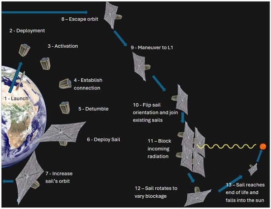
Figure 1.
Planetary sunshade system concept of operations, imagery used is for demonstrative purposes [10,11].
The system envisions the planetary sunshade as a mosaic of small satellites, each equipped with the sunshade sail as its primary payload and sharing a common bus architecture to support core satellite functionalities. Meaning once at L1* a single sunshade will join a collection of shades to block the required amount of radiation.
This paper intends to initiate the long process of designing specifics of the planetary sunshade system. The paper focuses specifically on the structural systems of the shade, including the frame, the sail, and the deployment mechanism. The frame houses many of the electrical systems, keeping them safe by distributing loads. The sail is the part of the satellite which will accomplish the blocking of radiation, with the deployment mechanism being the solution to how this sail will be unfolded. This subsystem was chosen for design as key dimensions like the sail area will define many other aspects of the satellite and the overall space mission.
2. Methodology
The design methodology employed to develop the system is based on a standard engineering design approach as laid out by the European Cooperation for Space Standardization (ECSS). The ECSS is an initiative with the goal of setting standards to facilitate coherent spacecraft design for use by all European space operatives [12]. The methodology outlined by contains seven key stages, although only the first four are within the scope of this paper. These steps are: mission analysis/needs identification, feasibility, preliminary definition, detailed definition, qualification and production, utilization, and disposal [13]. Decisions about the design were made using weighted decision matrices and validated with finite element analysis and representative models. The results of the detailed definition will be outlined in this paper.
3. Design
3.1. Requirements Definitions
This section resumes the steps to identify the main mission and system requirements as described in the ECSS design methodology [13]. The requirements for the project were not pre-established but instead set based upon the need to design a functioning and novel solution. A literature review highlighted what was required of the system to achieve these properties, creating the following list:
- Sail efficiency (Q) shall be less than or equal to 0.5.
The sail efficiency (Q) is a value from 0 to 1 that represents how well a sail converts the SRP into a force. The smaller the value for Q, the lower the mass of the sunshade can be, as defined by Equation (1), which describes the forces acting on the sail to create equilibrium. Thus, it makes sense to design a sail with a small sail efficiency. A value of 0.5 was chosen specifically as it is the value that a system incorporating state-of-the art technology is capable of achieving [6].
where
G = gravitational constant, ME = mass of the Earth, MS = mass of the Sun;
rsh = distance of sunshade from Earth, rs = distance from sun to Earth;
ωE = Earth’s angular velocity around the Sun;
PE = solar radiation pressure; ASH = sail area; MSH = mass of the sail.
Q is the sail efficiency, η is reflectivity, εF and εB are front- and back-emissivity coefficients.
- 2.
- A single sail shall be no smaller than 196 m2.
A larger sail will reduce the total number of satellites required to be launched to achieve the desired blockage. However, there are many design problems when designing large sails. The largest sail successfully deployed so far is IKAROS, with an area of 196 m2 [14]. Creating a system larger than this is desirable to make the design innovative and reduce the total number of satellites.
- 3.
- A single sail should have an estimated lifespan of 30 years.
It has been estimated that it will take 30 years after the technology has been developed to deploy all shades [9]. A 30-year lifespan means that the first satellite will need to be replaced once all have been deployed, reducing the required manufacturing and deployment rate. Furthermore, it has been estimated that cutting-edge technology could achieve a satellite life span of greater than 50 years, which makes 30 achievable [7].
- 4.
- The areal density of a single sail should be small enough to allow the shade to operate near the modified Lagrange point, L1*, where the gravitational and radiation pressure forces are in equilibrium.
The total weight of the system directly affects the cost of deploying the satellite. The cost of launching an object into space is determined by its weight; heavier objects are more expensive. Therefore, to reduce the cost of the project, the sail should operate at the point where the sail can stay in equilibrium for the smallest mass possible, known as the L1* position (see Figure 2). To reduce the average global temperature by 2 °C, which would bring the Earth back to pre-industrial temperatures, 1.8% of incoming photons must be blocked. At this minimum position, the total area required to achieve this is 6.75 × 10⁶ km2.
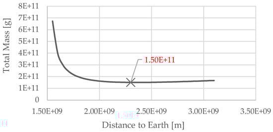
Figure 2.
Graph showing the position of the sunshade required for equilibrium for different masses and sail efficiencies (Q), where 1.5 × 10⁹ m = L1. The cross represents the point of minimum mass.
- 5.
- The sail should stay at its correct position within the constellation.
A sail that drifts away from its intended position could cover or collide with other sails. This would decrease the efficiency of the sunshade, requiring more sails than the initial estimated amount.
- 6.
- The sail could be capable of reaching L1* from Earth orbit under its own propulsion.
It has been proposed in the literature that the sunshade could reach L1* by acting like a regular solar sail [6]. This would be desirable to reduce fuel costs, but it is not essential if greater cost savings can be achieved without it.
- 7.
- The area blocked by the shade shall be reversible.
The sunshade will not be a permanent implementation; after the Earth has cooled sufficiently and global emissions have dropped, the temperature will need to be increased again. In addition, the sunshade could have unforeseen consequences that require reversal [3].
- 8.
- The sail deployer shall have a radius expansion ratio of 5 or greater.
From existing shade designs, most have a radius expansion ratio of around 5 [15]. The sunshade system should improve existing designs and therefore be greater than this value.
- 9.
- The bus interface shall withstand axial and lateral forces caused during launch on an Atlas V (see Figure 3).
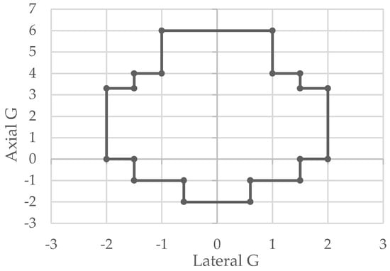 Figure 3. Range of axial and lateral static loads experienced during launch by payloads on an Atlas V [16].
The sail needs to withstand the forces imparted on it during launch so that it can still deploy when it reaches its target.
- 10.
- The bus interface shall be able to connect with Atlas V’s standard payload adapter.
The sunshade needs to be transported into orbit, and the Atlas V was chosen as an example launch vehicle [16].
3.2. Frame Analysis and Design
Considering the requirements definition, a solution based on a small satellite has been considered and designed. The satellite consists of two main sections: the payload section, with the deployment mechanism, and the bus section with all the standard subsystems essential for satellite operability. In this section, the satellite frame will be considered and analyzed in order to prove requirement number 9.
An iterative finite element analysis (FEA) approach was used to optimize the frame design to create a design that reduces the deformations caused by the launch loads. The static load applied to the model was a 6G axial load as this is the highest axial acceleration imparted onto a payload on an Atlas V [16]. It was assumed that this acceleration was uniform and that the base of the frame was fixed in place.
The process started out with a standard Cubesat 12U frame [17] design as this would sufficiently facilitate the initial estimation for mass and size. Furthermore, following a standard such as a CubeSat would allow for easier deployment and construction. However, as the project progressed, and FEA was conducted on the design, the geometry of the frame changed to better suit the requirements. The main parameters that the frame was designed around were to minimize weight and size whilst maintaining a stress that did not go over the ultimate tensile stress (UTS). The material of the frame was chosen using a decision matrix, Table 1, then a specific grade decided upon by evaluating the requirements of the frame and performing hand-calculations. The result of which was the decision to use aluminum 6061.

Table 1.
Sunshade frame material decision matrix.
The result of the iterative FEA process is a design with a max deformation of 2.89 mm (see Figure 4), located on the top surface and a max stress of 0.95 MPa located on the lower struts.
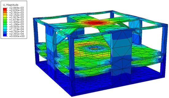
Figure 4.
Finite element analysis model showing the deformation of the frame under a 6G load, units in m.
Whilst this model is not perfect, as it assumes the frame is a single part and the launch loads would not be distributed perfectly, it provides evidence that the frame will survive to the launch load environment.
A common technique used in spacecraft design is the use of honeycombing, placing a honeycomb lattice between two sheets of metals such as aluminum to reduce weight but maintain strength [18].
Analysis has been conducted proving that selecting as frame material an aluminum 6061 plated, 5056 honeycombed sandwich reduces the mass considerably at the cost of a reduced strength but still satisfies the conditions imposed by requirement 9 [18]. By taking the volume of the surfaces that need to be changed and multiplying it by the density of the honeycomb (50 kg/m3) and then adding 2 plates equal to each side of areal density 1.35 kg/m2, a new weight can be calculated [18]. By changing the largest plate surfaces to sandwich honeycomb, the weight is reduced to 2.95 kg.
Changing large parts of the frame to the honeycomb will have effects on its reaction to loads. Whilst fully modeling the honeycomb is beyond the scope of this paper, a simplified model which changes the properties of the entire frame to ones of equivalent value will provide an estimate of the frame’s response. First, the density is reduced to 290 kg/m3, which is calculated by assuming a nominal honeycomb thickness of 10 mm and a plate thickness of 1 mm and then calculating the average density of this stack. Next the properties must be adjusted, aluminum’s normal young’s modulus is 69 GPa [19] which is reduced to 669 MPa [18]. Using these properties with the same boundary conditions of the previous model gives a result of 3.2 × 10⁻⁵ m max displacement and 0.1 MPa max stress. This result suggests that replacing surfaces with honeycomb sandwiches will have no adverse effects.
The frame needs to survive dynamic loads, the dynamic loads analyzed were vibration and shock. The response for these was calculated by simplifying the system to a mass and spring-damper system, where a mass is placed on top of a spring and damper and a force is applied to it. For the Atlas V, the worst-case vibration is an acceleration of 0.9 G at a frequency of 100 Hz [16]. The natural frequency of the system is 1755 Hz, so the vibration of the rocket does risk causing a resonance.
The second dynamic load is a shock load caused by separation. For the Atlas V, the worst-case scenario is a 4500 G load for 0.4 ms [16]. The vibration responses of the payload are shown in Figure 5.
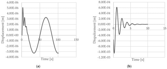
Figure 5.
(a) Vibration response of the payload to a worst-case scenario load of 0.9 G at 100 Hz, (b) worst-case shock response of 4500 G load for 0.4 ms.
3.3. Sail Design
The sail design was chosen by comparing several existing designs, using paper prototypes to assess properties. The outcome of this was a sail design made up of four equal sized triangular segments, deployed by booms and rolled onto spools. To keep the sail in equilibrium at the L1* position, the area of the sail is required to be 1297 m2. This requires an effective folding method to allow the sail to fit onto the launch vehicle. The prototyping showed that vertical folds were the most efficient, with a design from research for the Advanced Composite Solar Sail System [20] being improved for this system. The design was changed to add more folding lines, reducing the height of the sail when it is folded. Similar vertical-fold deployment concepts have also been implemented in JamSail mission [21], where the folding pattern was optimized for manufacturability and minimized storage volume.
The sail is folded in alternating peaks and troughs which when pushed together forms a long flat strip that can be wrapped around the central spool. The folding sail folding pattern, with the folding process is shown in Figure 6, Figure 7 and Figure 8.
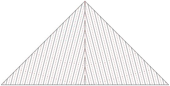
Figure 6.
Sail folding pattern, red dotted lines indicate peaks, and black solid lines indicate troughs.
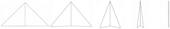
Figure 7.
Sail folding process from a top-down perspective.

Figure 8.
Folded sail from a side perspective where the dotted lines represent folds and the solid lines represent the sail’s edge.
The material the sail is made of has a large impact on its properties and the effect on the rest of the satellite. There are three sections of the sail that need a material selection: membrane, front coating, and back coating. The membrane needs to have a good specific strength to withstand deployment loads but also reduce the total satellite weight. The front coating needs to be an absorbent material, and the back coating needs to be an emissive, reflective coating. Of the materials reviewed, mylar provided the best characteristics for the membrane. To decide on the coatings, existing products were reviewed to arrive at an idea of current industry capabilities. Fractal Black [22] and Aptek [23] are space graded coatings which in combination provide the best sail efficiency whilst staying in equilibrium at L1*.
3.4. Deployment Mechanism
Booms were selected as the most suitable deployment method, as briefly mentioned in Section 3.3. This was decided upon with the use of a decision matrix which compared the viable deployment method and sail shape combination. The potential deployment alternatives were centrifugal deployment and shape memory deployment. Values were selected for the decision matrix with estimations on the weight of the deployment system and by accessing paper prototypes of the sail design each deployment method allowed for. Furthermore, research was conducted into solar sails to assess the common methods for deployment and find problems that arose.
The booms of the planetary sunshade needed to be made of a material with a good specific strength. Whilst the loading on the booms will be small due to microgravity, there will still be some amount of loading from the SRP and required maneuvers. To select an appropriate material, lightweight, flexible materials were researched. If the material is not able to coil well, then it will require more force to keep it spooled which increases complexity and weight. Among the materials evaluated, CFRP was selected for its high specific stiffness, flexibility, and spaceflight heritage in deployable structures.
Each of the booms is 27 m × 0.1 m × 0.2 mm, this is long enough to pull the sail completely out, connect to the spool, and help to reduce the angle between the sail end and the boom end. In addition, each boom has a half elliptical cross-section when deployed which is achieved by pushing it through a curved hole. The ellipse has a horizontal to vertical height ratio of 0.8, this provides the lowest total stress in the axial and lateral directions for a unit load (see Figure 9). The boom section dimensions are represented in Figure 10.
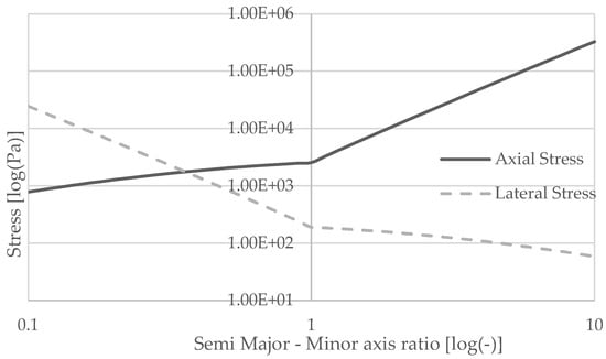
Figure 9.
Graph representing how the ratio of semi-major–minor axis for a semi-elliptical boom cross-section affects stress under a unit load.
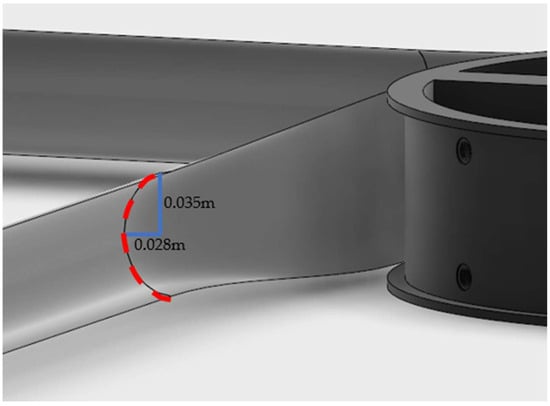
Figure 10.
Boom cross-section when deployed (red dashed line representing the section, and blue lines the dimensions).
The sail and boom spools both have a diameter of 0.5 m as this reduces the angle between the direction of force and direction of movement whilst still fitting within the 0.6 m × 0.6 m frame. The spools are the same height as the parts wrapped around them, with a rim on both ends to keep these spooled parts in place. The spools needed a low density to help reduce the total satellite weight but a high enough strength to survive launch. With these requirements polycarbonate was the most suitable.
The value of the deployment force is determined by the desired deployment speed and the frictional forces required to overcome. The time for the sail to deploy has no strict mission requirements, so for now, before in depth mission parameters are established, the deploy time will be assumed to be 5 min. The required length of the booms is 27 m so to deploy in 5 min the required acceleration is 0.0024 m/s2. Taking the weight of the spools, sail and booms which the motor must rotate and using F = ma, the force required is 5.39 × 10⁻² N. The boom spool has a radius of 0.5 m so the desired deliverable output torque is 13.47 mNm, calculated using τ = Fr. To find the minimum actuation torque, the resistive force must also be considered, for simplicity, only the frictional forces were considered [24]. The ECSS standards outline safety factors for each value that should be included when calculating the minimum actuation torque. When accounting for the safety factors and the frictional forces, the value for the minimum actuation torque is 39.3 mNm.
Therefore, the process by which the sail is deployed (shown in Figure 11) is as follows:
- A motor rotates the boom’s spool, pushing the booms outward through a curved hole which changes the boom’s cross-section.
- The boom spool continues to rotate and push the booms outwards, which in turn pulls the sail.
- This results in the rotation of the sail spool and the unfolding of the sail.
- The booms continue to deploy until the sail is fully unfolded and pulled taught.

Figure 11.
Sail deployment sequence: (a) initial configuration, (b) onset of deployment, (c) intermediate stage, and (d) fully deployed sail. Red arrows indicate the rotational motion of the spools and lateral movement of the booms. Subfigure (d.1) provides a close-up view of the sail attachment to the opening mechanism.

3.5. Weight Breakdown
The total mass of the satellite includes representative, off-the-shelf parts for the subsystem to give an idea of their weight (see Table 2). The planetary sunshade system will require a motor, an electric power and control system, attitude control system, communications, and on-board computer.
Table 2.
Representative subsystem weights.
This brings the total bus weight to 6.4 kg, when combined with a deployment mechanism weight of 2.8 kg as shown in the mass breakdown in Table 3, the required size of the sail is 1297 m2.
Table 3.
Satellite mass breakdown.
3.6. Final Design Overview
The final structural design of the satellite comprises the main frame, a cylindrical deployment mechanism, and a sunshade sail. Figure 12 presents the key system configurations: (a) the satellite in its stowed state, (b) a cross-sectional view detailing internal components, and (c) the deployed configuration illustrating the full extension of the sail.
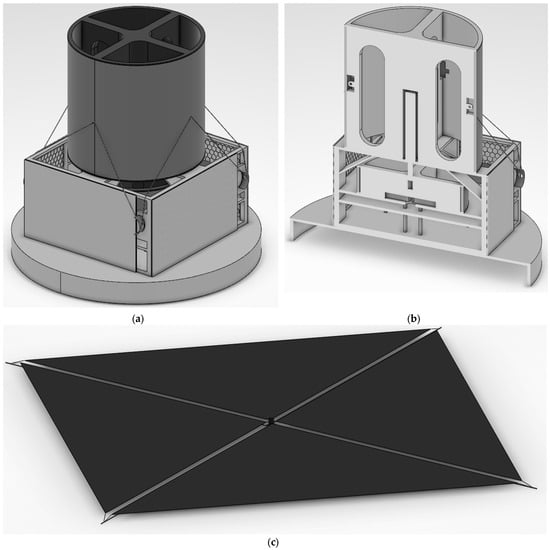
Figure 12.
(a) Stowed satellite design, (b) stowed satellite design cross-sectional view, (c) deployed satellite design.
In the stowed design, the cylindrical release mechanism is prominently mounted atop the satellite frame. The cross-sectional view highlights internal compartments dedicated to housing both the sail and the boom. The deployed configuration offers insight into the scale relationship between the satellite body and the extended sail.
3.7. Scale Model Prototype
It was not possible to perfectly recreate the planetary sunshade system at a smaller scale due to the limitations imposed by the preliminary nature of the project, such as the not incomplete identification of specific materials for the sail exact, and the sail being so much larger than the frame. To overcome this, 3D printing using PLA was used to build the frame with the booms being made from a sheet of CFRP and the sail made of mylar survival blankets. Building a 1297 m2 sail by hand is not feasible, so an area of 4 m2 scaled-down sail, with boom lengths of 1.5 m and a frame size of 128 mm × 128 mm × 68 mm, was constructed for testing. The frame could not be made to the same scale as the sail and so was scaled up to be four times larger.
The key design parameters for the model are therefore a 4 m2 sail with boom lengths of 1.5 m and frame size of 128 × 128 × 68 mm. The scale model with a singular sail section deployed is shown in Figure 13.
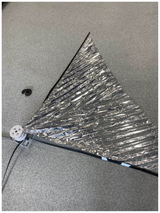
Figure 13.
Scale model with a singular sail section deployed.
4. Discussion
4.1. Assumptions Made During the Project
This paper deals with a preliminary design of the planetary sunshade system and serves just as simple evidence of possible results that are easily achievable with the limitations imposed. It does not aim to give the “final solution” but some suggestions on how to conduct the design, and what is possible to achieve. For this reason, it is subject to a few assumptions made to simplify the design process. The most impactful of these assumptions shall be discussed below.
The first assumption was that the gravitational pull on the sail was constant. The calculations used to assess the position of L1* did not factor in the Moon’s gravitational pull, the value of which changes over time as it orbits the Earth. The gravitational pull of the Moon as it moves around the Earth is quite small; the max force that the Moon will pull the satellite out of place with is 1.09 × 10⁻⁴ N. This creates only a small acceleration on the sail, but it will ideally last 30 years, so over time the velocity will build up. To counter the changing gravitational force L.M Catello has suggested for the planetary sunshade to be in an orbit around L1 instead of a fixed position [33]. This could have further implications on the loads applied to the sunshade which will need to be investigated at a future date.
The second assumption was that during the sail’s 30–year operating life the value of Q would not decrease. This is unlikely to be the case due to radiation degradation and potential micrometeorites. The project set out to assess these factors but was unable to do so due to time constraints. Future studies should use ESA’s SPENVIS tool [34] to quantify radiation effects and micrometeoroid damage over multi-decade mission lifetimes.
4.2. The Design
The design developed has some interesting implications and findings that are worth discussing. The sail folding technique chosen for this project is one that uses vertical folds. The authors’ assumptions going into the project were that a design utilizing origami folding techniques would yield the best results, due to existing research [14,15,35]. However, this was not the case, at least for the planetary sunshade. From the paper prototypes made, the designs that provided the best folding ratios were ones that employed simpler folding patterns.
Of course, it should be considered that the use of paper, which is far thicker than materials like mylar, could play a substantial role in this discrepancy as well as any imprecisions from the folding process. However, the results are still interesting and suggest that the difficult implementation of an origami folding pattern can cause the design to be less effective than desired. In addition, the use of these simpler folding patterns by more recent solar sails such as the solar cruiser [36] and NEA scout [37] suggests that origami sails still require greater development and understanding.
The sail efficiency of the system is 0.5 and with current coating materials it will be very difficult to reduce it further than this. Coatings that are suitable for a planetary sunshade are low-density but have poor absorbent and emissive properties. For the sail efficiency to be lowered further new materials will need to be developed which are lightweight but also provide good characteristics. A lower value of Q will increase the sail area and decrease the total weight which will result in fewer and cheaper rocket launches. This brings about its own challenges as deploying sails larger than 1700 m2, which a lower value of Q would create, has never been achieved.
4.3. The Scale Model
Despite the shortcomings of the model, some valuable information could still be gathered. It is likely that even the flexible CFRP chosen for the real boom design will want to spring back into place, so a system should be created to resist this force.
The calculations used to find the sail and booms spooled diameter are a large underestimation for the actual diameter. This is due to imperfection in the design and folding which are unlikely to be removed even when built on the full scale. The expected height of the sail when spooled was 3 cm but in reality, it was 7 cm, and the thickness should have been 1.1 cm but this was the thickness of just one sail when spooled. This is important information as it shows that a safety factor should be added to the dimensions to allow for imperfections in the design. This will be subject to further design consideration. The calculated sail radius is 25.5 m which when spooled shrinks down to 0.2517 m. This suggests a radius expansion ratio of 100 but this should be taken with skepticism based on these findings. The scale model sail was four times thicker than expected, so an expansion ratio of 25 is more realistic.
Finally, the scale model proved the difficulty of folding and creating the sail. Even for a 4 m2 sail, the process was very time-consuming and intricate. Whilst some aspects of this may be easier when at full scale, it still suggests that special manufacturing techniques will need to be developed if the sail is to ever be mass produced. This could involve some form of technique to easily create fold lines on the sail.
5. Conclusions
This study successfully addresses the early-stage structural design of a planetary sunshade, including feasibility validation and system mass estimation, laying the foundation for future performance testing and mission planning. The system has been proven to have a sail efficiency factor of less than or equal to 0.5. The radius expansion ratio of the sail is greater than 5 and can survive the loads imparted on it by the Atlas V’s launch. However, the project was not able to prove that the sail could last 30 years at the L1* position. That is not to say that it is impossible to prove but the process of doing so was underestimated, resulting in too little time for the necessary steps.
On reflection, a greater effort regarding how this could have been measured should have been established early in the project. The methodology employed to achieve these aims was a standard design process laid out by the ECSS. The design process employed methods like finite element analysis and representative models to assess the response of the system. Both stages included a review to make sure the project was on-track. Finally, a scale model was created to put the theory into practice and understand what assumptions made should no longer be considered true.
Overall, the project was successful, but more time could have been, and will need to be, spent analyzing the effects of solar radiation on the sail before the structure design can truly be considered finished. This was not developed due to the lack of time. This does however provide a valuable steppingstone for future academics to know what works and spend more time on other design aspects which were out of the scope of this project. In addition, the findings can guide future endeavors and highlight issues that need to be investigated and solved.
The next steps would be to work on the areas that had to be skipped due to time constraints. Further FEA should be conducted on the deployment mechanism and sail to assess their response to loading and ensure they can operate successfully. The longer-term goals of the project include a larger scale model, followed by a real-size engineering model and then finally an in-orbit demonstration test, providing a clear course to follow.
Author Contributions
The research article is the result of a project conducted mainly by the first author, J.T., with the continued supervision and advice of C.C.; writing: original preparation: J.T.; writing: review, editing, and content evaluation; N.P.; conceptualization, supervision, and final review: C.C. All authors have read and agreed to the published version of the manuscript.
Funding
This research received no external funding.
Data Availability Statement
The raw data supporting the conclusions of this article will be made available by the authors on request.
Acknowledgments
The authors wish to thank the NottSpace team and the Department of Mechanical, Materials and Manufacturing Engineering at the University of Nottingham for their continued support.
Conflicts of Interest
The authors declare no conflicts of interest.
Abbreviations
The following abbreviations are used in this manuscript:
| FEA | Finite Element Analysis |
| ECSS | European Cooperation for Space Standardization |
| SAI | Stratospheric Aerosol Injection |
| L1 | Lagrange Point 1 |
| CFRP | Carbon Fiber-Reinforced Polymer |
| PLA | Polylactic Acid |
| ESA | European Space Agency |
| OADCS | Orbit and Attitude Determination and Control Systems |
| EPS | Electrical Power System |
| TTC | Telemetry, Tracking and Command |
| OBC | On-Board Computer |
References
- United Nations Environment Programme. Emissions Gap Report 2024; United Nations Environment Programme: Nairobi, Kenya, 2024. [Google Scholar]
- Sánchez, J.-P.; McInnes, C.R.; Marchis, F. Optimal Sunshade Configurations for Space-Based Geoengineering near the Sun-Earth L1 Point. PLoS ONE 2015, 10, e0136648. [Google Scholar] [CrossRef] [PubMed]
- Azriel, M.; Amrouni-Keiling, A.; Cappaert, J.; DeLatte, D.; Henry, A.; Kovács, R.; Platzer, P.; Wong, N.; Welch, C. Weighing Geoengineering: An Interdisciplinary Assessment of the Space-Based Solar Shield. Int. J. Clim. Change Impacts Responses 2013, 4, 103–117. [Google Scholar] [CrossRef]
- Planetary Sunshade Foundation. State of Space Based Solar Radiation Modification; Planetary Sunshade Foundation: Los Angeles, CA, USA, 2023; pp. 4–9. [Google Scholar]
- Fix, S. Feasibility Study of a Sunshade in the Vicinity of the Sun Earth L1 Lagrange Poin; University of Stuttgart, Planetary Sunshade Foundation: Stuttgart, Germany, 2021. [Google Scholar]
- Fuglesang, C.; de Herreros Miciano, M.G. Realistic sunshade system at L1 for global temperature control. Acta Astronaut. 2021, 186, 269–279. [Google Scholar] [CrossRef]
- Angel, R. Feasibility of Cooling the Earth with a Cloud of Small Spacecraft near the Inner Lagrange Point (L1). Proc. Natl. Acad. Sci. USA 2006, 103, 17184–17189. [Google Scholar] [CrossRef] [PubMed]
- Coco, M.; Matonti, C.L.; Cappelletti, C.; Chesley, B.; Fuglesang, C.; Governale, G.; Pushparaj, N.; Romano, M.; Tibert, G.; Wilk, L. Planetary sunshade for solar geoengineering: Preliminary design of a precursor system and mission. Acta Astronaut. 2025, 235, 452–462. [Google Scholar] [CrossRef]
- Matonti, C.L.; Coco, M.; Governale, G.; Wilk, L.; Shimazaki, T.; Krantz, E.; Pushparaj, N.; Mao, H.; Tibert, G.; Cappelletti, C.; et al. A Roadmap toward a Planetary Sunshade for Space-based Solar Geoengineering. In Proceedings of the 75th International Astronautical Congress, Milan, Italy, 14 October 2024. [Google Scholar]
- Branz, F.; Cappelletti, C.; Ricco, A.J.; Hines, J. (Eds.) Next Generation CubeSats and SmallSats: Enabling Technologies, Missions, and Markets; Elsevier: Amsterdam, The Netherlands, 2023. [Google Scholar]
- Spradling, J. Artist’s Rendition of Lightsail 2 in Earth Orbit. Available online: https://www.planetary.org/space-images/ls2-earth (accessed on 25 August 2025).
- European Space Agency. European Cooperation for Space Standardization. Available online: https://ecss.nl/ (accessed on 15 April 2025).
- ECSS-M-ST-10C Rev.1; Project Planning and Implementation. ECSS Secretariat ESA-ESTEC: Noordwijk, The Netherlands. Available online: https://ecss.nl/standard/ecss-m-st-10c-rev-1-project-planning-and-implementation/ (accessed on 25 August 2025).
- Tsuda, Y.; Mori, O.; Funase, R.; Sawada, H.; Yamamoto, T.; Saiki, T.; Endo, T.; Yonekura, K.; Hoshino, H.; Kawaguchi, J.I. Achievement of IKAROS—Japanese deep space solar sail demonstration mission. Acta Astronaut. 2013, 82, 183–188. [Google Scholar] [CrossRef]
- Chen, T.; Bilal, O.R.; Lang, R.; Daraio, C.; Shea, K. Autonomous Deployment of a Solar Panel Using Elastic Origami and Distributed Shape-Memory-Polymer Actuators. Phys. Rev. Appl. 2019, 11, 064069. [Google Scholar] [CrossRef]
- United Launch Alliance. Atlas V Launch Services, User’s Guide; United Launch Alliance: Centennial, CO, USA, 2010. [Google Scholar]
- The CubeSat Program. CubeSat Design Specification. Revision 14; Cal Poly: San Luis Obispo, CA, USA, 2022; Available online: https://static1.squarespace.com/static/5418c831e4b0fa4ecac1bacd/t/62193b7fc9e72e0053f00910/1645820809779/CDS+REV14_1+2022-02-09.pdf (accessed on 25 August 2025).
- Hexcel Composites. HexWebTM Honeycomb Sandwich Design Technology. December 2000. Available online: https://mecway.com/forum/uploads/FileUpload/38/1279af91c13830e36e59c40671f067.pdf (accessed on 25 August 2025).
- World Material. Aluminum 6061, Al 6061-T6 Alloy Properties, Density, Tensile & Yield Strength, Thermal Conductivity, Modulus of Elasticity, Welding. Available online: https://www.theworldmaterial.com/al-6061-t6-aluminum-alloy/ (accessed on 20 April 2025).
- Stohlman, O.R.; Fernandez, J.M.; Dean, G.; Schneider, N.; Kang, J.H.; Barfield, R.; Herndon, T.; Stokes, P. Advances in Low-Cost Manufacturing and Folding of Solar Sail Membranes. In Proceedings of the AIAA Scitech 2020 Forum, Orlando, FL, USA, 6–10 January 2020. [Google Scholar]
- Cormier, L.; Yousif, T.; Thompson, S.; Arcia Gil, A.; Pushparaj, N.; Blunt, P.; Cappelletti, C. Preliminary Design of a GNSS Interference Mapping CubeSat Mission: JamSail. Aerospace 2024, 11, 901. [Google Scholar] [CrossRef]
- Acktar Advanced Coatings. Acktar Black World’s Blackest Coatings. Available online: https://acktar.com/wp-content/uploads/2024/04/Direct-Coating-15.2.24.pdf (accessed on 12 April 2025).
- Aptek. Aptek 2711-1 Technical Aata & Information. Available online: https://apteklabs.com/wp-content/uploads/2023/01/2711-1.pdf (accessed on 12 April 2025).
- ECSS-E-ST-33-01C; Space Engineering Mechanisms. ECSS Secretariat ESA-ESTEC: Noordwijk, The Netherlands. Available online: https://ecss.nl/standard/ecss-e-st-33-01c-rev-2-1-march-2019-space-engineering-mechanisms/ (accessed on 25 August 2025).
- Thin Gap. LS Frameless Motor Kit. Available online: https://www.thingap.com/wp-content/uploads/2021/11/LSI-25-10-Datasheet-Rev_D.pdf (accessed on 22 April 2025).
- Ibeos. E28-200 28V SmallSat Electric Power System (EPS). Available online: https://satsearch.co/products/ibeos-28v-smallsat-electric-power-system (accessed on 22 April 2025).
- AAC Clyde Space. OPTIMUS-40. Available online: https://satsearch.co/products/aac-clyde-optimus-40 (accessed on 22 April 2025).
- Innovative Solutions in Space B.V.(ISIS). Antenna System for 6U/12U CubeSats. Available online: https://satsearch.co/products/isis-antenna-system-for-6u-12u-cube-sats (accessed on 22 April 2025).
- Yan, B.; Qin, L.; Tao, S.; Fang, G. Development and challenges of large space flexible solar arrays. Space Sol. Power Wirel. Transm. 2025, 2, 33–42. [Google Scholar] [CrossRef]
- CAVU Aerospace UK. OBC-Cube-Polar Cubesat OnBoard Computer. Available online: https://satsearch.co/products/cavu-corp-obc-cube-polar (accessed on 22 April 2025).
- Satlab A/S. SRS-4 Full-Duplex High-Speed S-Band Transceiver. Available online: https://satsearch.co/products/satlab-srs-4-s-band-transceiver (accessed on 22 April 2025).
- Space Inventor. WHL-200. Available online: https://satsearch.co/products/space-inventor-whl-200 (accessed on 22 April 2025).
- Catello, L.M.; Marcello, R. New Families of Halo Orbits about the Photo-Gravitational Equilibrium in the Sun—Earth–Moon System’s Center of Mass Elliptic Restricted Three Body Problem for Planetary Sunshade Missions. In Proceedings of the 75th International Astronautical Congress, Milan, Italy, 14 October 2024. [Google Scholar]
- Royal Belgian Institute for Space Aeronomy. SPENVIS. 2024. Available online: https://www.spenvis.oma.be/ (accessed on 22 April 2025).
- Zhao, P.; Wu, C.; Li, Y. Design and application of solar sailing: A review on key technologies. Chin. J. Aeronaut. 2023, 36, 125–144. [Google Scholar] [CrossRef]
- Zachary, K.M.; Mark, S.L. Design and Testing of a Deployment Mechanism for NASA’s 1,653-m2 Solar Cruiser Sail. In Proceedings of the 47th Aerospace Mechanisms Symposium, NASA Langley Research Center, Virginia Beach, VA, USA, 15–17 May 2024. [Google Scholar]
- Sobey, A.R.; Lockett, T.R. Design and Development of NEA Scout Solar Sail Deployer Mechanism. In Proceedings of the 43rd Aerospace Mechanisms Symposium, Santa Clara, CA, USA, 4–6 May 2016. [Google Scholar]


Disclaimer/Publisher’s Note: The statements, opinions and data contained in all publications are solely those of the individual author(s) and contributor(s) and not of MDPI and/or the editor(s). MDPI and/or the editor(s) disclaim responsibility for any injury to people or property resulting from any ideas, methods, instructions or products referred to in the content. |
© 2025 by the authors. Licensee MDPI, Basel, Switzerland. This article is an open access article distributed under the terms and conditions of the Creative Commons Attribution (CC BY) license (https://creativecommons.org/licenses/by/4.0/).