Article

Ion Source—Mathematical Simulation Results versus Experimental Data

by
Victoria V. Svotina
*,
Maria V. Cherkasova
,
Andrey I. Mogulkin
,
Andrey V. Melnikov
and
Oleg D. Peysakhovich
Research Institute of Applied Mechanics and Electrodynamics of the Moscow Aviation Institute, 125080 Moscow, Russia
*
Author to whom correspondence should be addressed.
Aerospace 2021, 8(10), 276; https://doi.org/10.3390/aerospace8100276
Submission received: 19 July 2021 / Revised: 14 September 2021 / Accepted: 17 September 2021 / Published: 23 September 2021
(This article belongs to the Section Astronautics & Space Science)

Abstract

:
To develop elements of a system for contact-free transportation of objects in space has now become an urgent task for the contemporary space-related activities. The purpose of work that is presented hereinafter was to conduct ground tests of the ion source, which is a key element of the above-mentioned system, and to compare the obtained experimental data with the mathematical simulation results in order to build a refined physical and mathematical model of the ion source. Such model was built on the basis of the classical problem regarding the motion of charged particles in an electrostatic field. Parameters of the ion source have been determined experimentally for several operating modes using various structural designs of the ion source electrodes. Two types of ion optics were tested—with slit and round apertures. Good correlation between simulation results and experimental data has been demonstrated. The optimum ion source operation modes have been identified to ensure minimum divergence angles for the plasma beam exiting from the ion source, which in its turn maximizes the pulse transmitted to the transported object.

1. Introduction

The service spacecraft (SSC) can be used to insert a new spacecraft (SC) into operating orbit or to perform its orbit raising in the event of the main propulsion system failure in order to extend the lifetime of operating SC by raising its orbit or transferring the SC into other operating orbits, as well as to remove dead or failed SC into graveyard orbits.
Various ways of SC transportation between orbits and their removal from operating orbits by SSC are being considered by the world scientific community. Various types of space tugs (FREND [1], SMART–OLEV [2], EDDE [3], SUMO [4], ODDS [5], ROTEX [6], and ESS [7,8]); space tether systems (the space elevator, electro-dynamic tether [9,10]); SC capturing using throw-nets (ROGER SC by EADS Astrium team (ESTEC, Noordwijk, The Netherlands) and QinetiQ (Farnborough, England, UK) [11,12]) and various harpoon and laser systems [13], solar and magnetic sails [14] have been proposed. Comparison of the listed concepts is of a subjective nature because none of the mentioned concepts has been fully implemented from the engineering standpoint and none has been tested in actual spaceflight conditions. Each concept has its pros and cons.
An ion source (IS), which is being developed for its use onboard an SSC as part of a system for contactless transportation of passive space objects (SO) is the main object of the present study.
Transportation of SOs by an ion beam was initially proposed to perform transportation in the “Earth-Moon” system [15]. A similar principle for space debris (SD) removal was subsequently proposed by Japanese [16] and European [17,18] experts. Such SD removal method was named the Ion Beam Shepherd.
Relevance of the proposed method is driven by the contemporary trends to secure safety of space-related activities in the long-term by implementing all possible methods to protect and clean the near-Earth space from man-made SD. This point has been validated by development efforts for a large number of space system projects to ensure transportation of dead or failed SC to graveyard orbits, which are sponsored by the space agencies of the nations that participate in space-related activities and by members of the United Nations Organization [19,20].
The use of the ion source for transportation of dead SC or SD appears to be the most promising area of its use due to SO material ablation that is observed during Space Object transportation by an IS jet.
The SD removal problem has now become exceptionally urgent, and it can be formulated as follows: if in the coming decades there is no transition to new rocket and space hardware technology in order to prevent the SD number growth, then in 50–60 years the near-Earth space environment contamination with SD will significantly complicate further space-related activities, which, in turn, will negatively affect the global economy [11,19].
An increase in the number of SO in near-Earth orbits as a function of time is shown by the plot below (Figure 1 [21]). The increase of SO mass and area is in approximately the same proportion. It should be noted, though, that currently it is impossible to reliably track SD with a size below 1 m in and around GEO due to limitations in sensitivity of radars and telescopes; therefore, there are many more unidentified and unaccounted SO in the GEO region.
By January 2019, an estimated number of SD fragments in near Earth orbits amounted to 34,000 fragments larger than 10 cm in diameter, 900 thousand SD fragments ranging from 1 cm to 10 cm, and more than 129 million SD fragments less than 1 cm [22].
The problem of the man-made near-Earth space pollution is particularly acute in relation to the region of low-Earth orbits and to the GEO region because at the altitudes of up to 600 km, SD re-enters the Earth’s atmosphere in several years, while centuries are required to do so at altitudes above 1000 km [23].
High SD velocities around the Earth pose a severe threat to SC that are being launched into operating orbits and to SC that are already operating there, including crew vehicles. According to experts, the risk of a catastrophic collision between the Space Shuttle type spaceship and SD was roughly rated as 1 to 300. The same risk for the Hubble Space Telescope was rated as 1 to 185 due to the fact that the Telescope’s operating orbit is more populated with SD. The International Space Station performs a collision avoidance maneuver when the probability of collision is 1 to 10,000 [24].

2. The Status of the Problem

High-frequency ion thruster (HFIT) has a number of advantages that ensure its effective use to eliminate space debris objects. The advantage of this type of thrusters is the absence of a high-current cathode in the discharge chamber because the discharge is independent. Electrodes are removed from discharge chamber. No magnetic system is needed, and the design is generally simpler due to the small number of structural elements. During operation, high uniformity of current density distribution near the emission electrode (screen greed) and low erosion of the emission electrode is ensured. It is possible to use strong throttling of mode parameters by ion beam current and thrust.
Results of preliminary analysis regarding the feasibility to use an IS to remove SD to a graveyard orbit show that this method is a promising solution to the GEO pollution problem [25]. An important advantage of this method is that SDs are removed without any mechanical contact between the SSC and SD. It is safer from the perspective of potential collision between two bodies. In addition, there are no issues related to docking the SSC to SD that is normally tumbling relative to its center of gravity, and the robotic arm systems to capture space debris are not required [25].
Simulation of the ion beam force and erosive action on SD was carried out by means of calculation in [26,27]. Problems of SSC control during SD transportation by the ion beam are studied in [28,29].

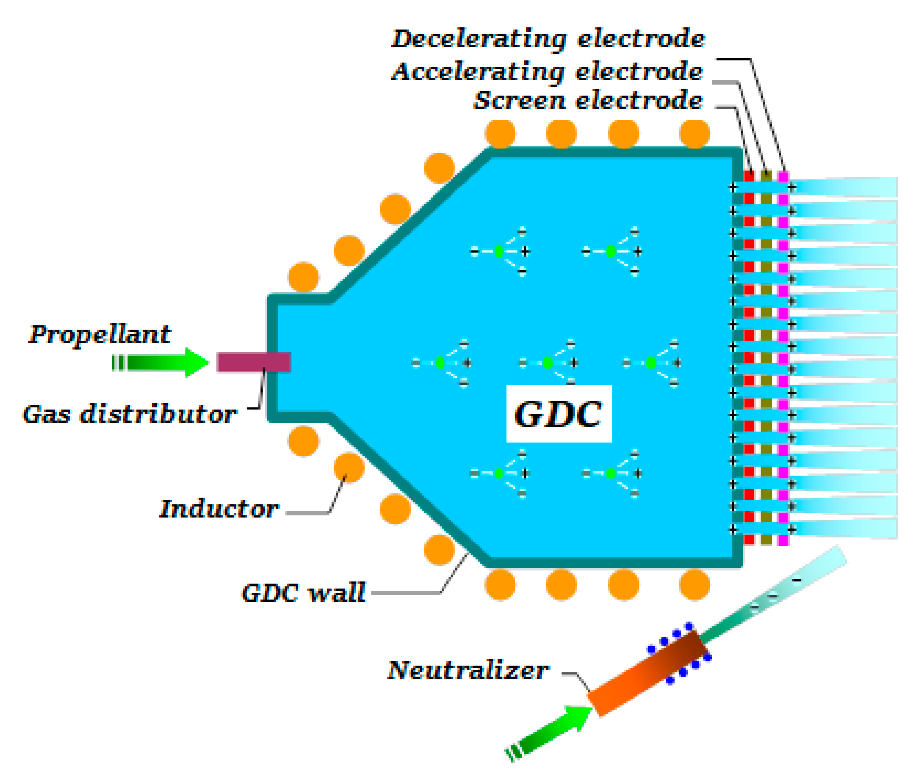
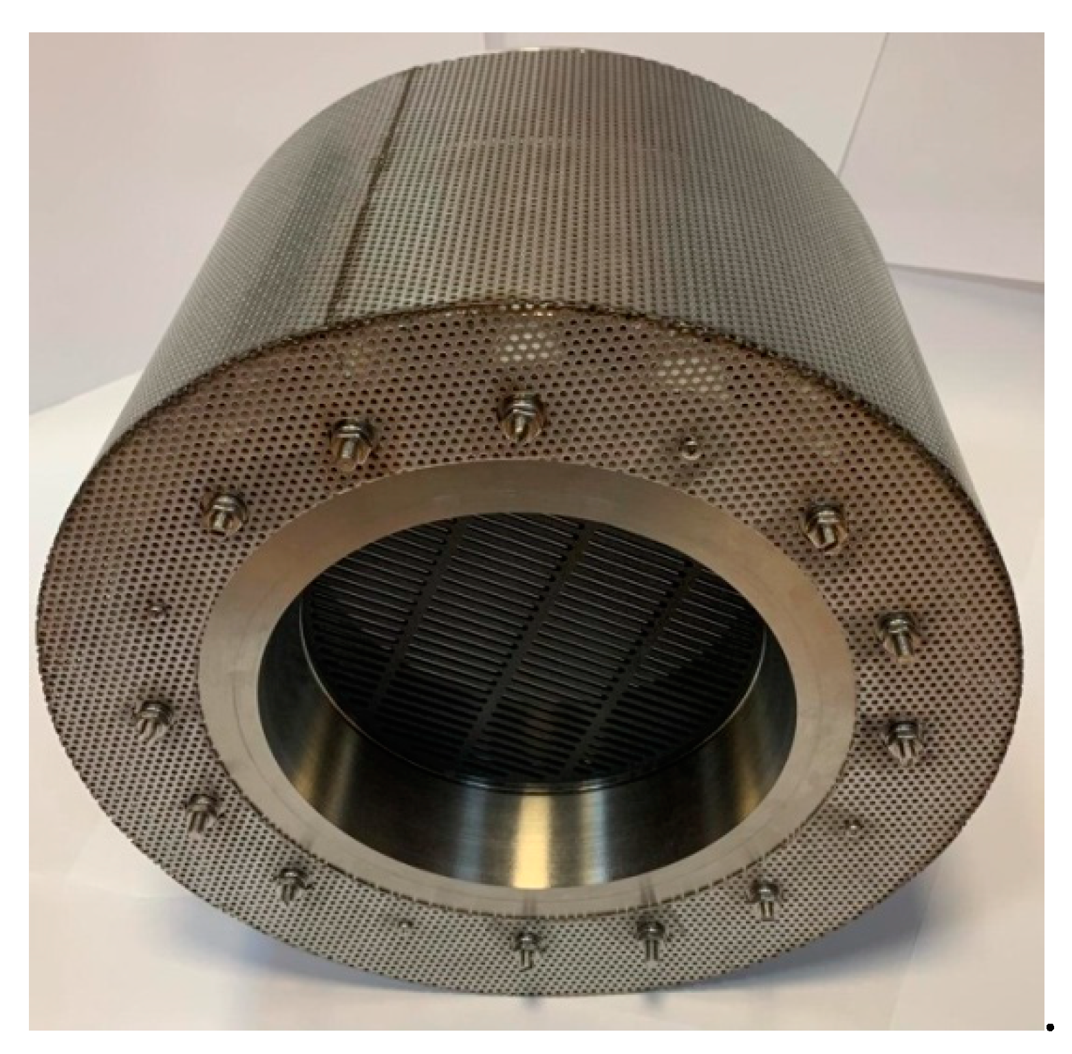
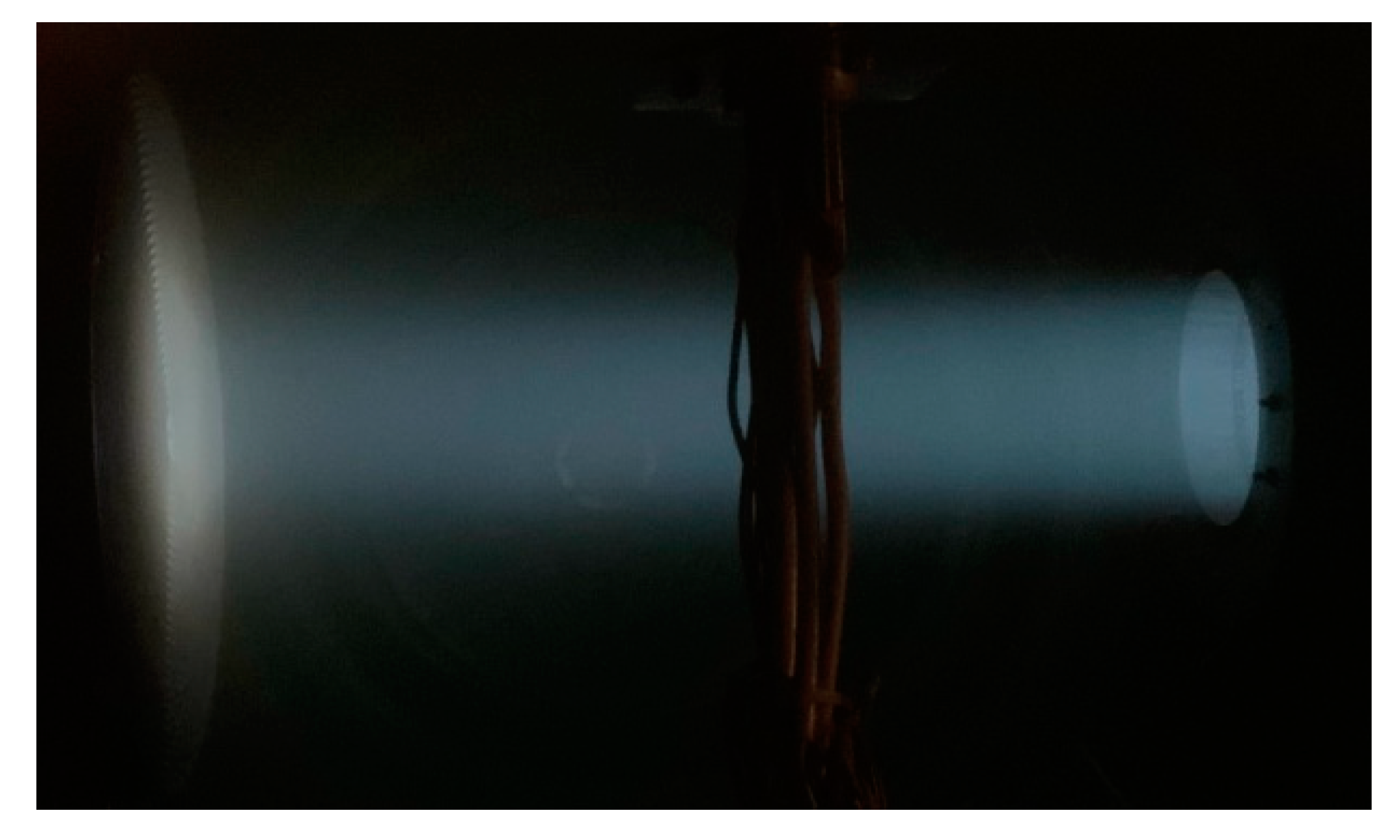
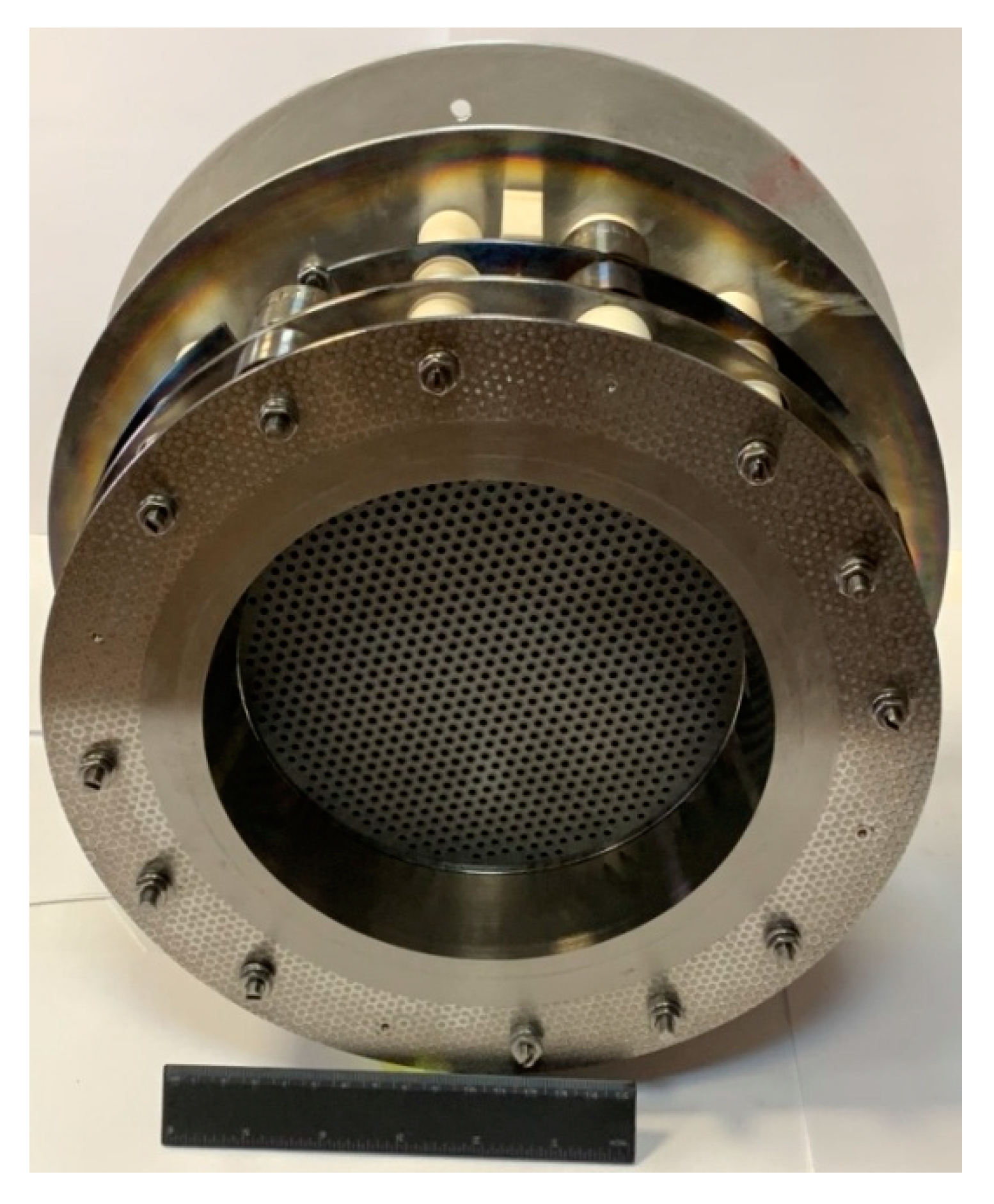
2.1. The Ion Source (IS)

The IS includes three main units: an extraction system (ES), an outer flange unit, and a gas discharge chamber (GDC) (Figure 2). The ES includes screen, accelerating, and decelerating electrodes. The GDC serves to ionize the plasma-forming gas and can be made of a radio-transparent dielectric (quartz, aluminum oxide, etc.) in various configurations: a cylinder, a truncated cone, a dome. There is an inductor located outside the GDC that is used to input power into the discharge from a radio-frequency generator. Acceleration of the ionized propellant occurs in the ES due to the potential difference applied to the electrodes.
The IS distinguishing characteristic is that the only thermal power source is the electromagnetic field initiating an inductive discharge. The main processes that stipulate the IS thermophysical state are the following.
A neutralizer based on a hollow cathode is installed near the ion thruster/source exit plane in order to neutralize the ion beam by emitting electrons. The plasma-forming gas is fed into the GDC through the gas distributor. The inductive radio-frequency discharge is initiated by applying a negative voltage pulse to the neutralizer following gas supply and RF power input. The ion beam is generated when voltage is applied to the ES electrodes. Quasi-neutral plasma is generated downstream from the ES decelerating electrode. Plasma density is governed by the ions beam and by slow ions originating in the gas as a result of the process of resonant charge-exchange of the beam fast ions with propellant atoms flowing out of the gas-discharge plasma. The plasma density in the neutralization zone is lower than the plasma density in the GDC by two orders of magnitude, approximately. The position of the electrodes is selected so that the distribution of potential of the electrostatic field along the beam keeps the electrons in the potential well of the volume charge of ions and does not pass them to the ion source.
The RF discharge is insensitive to foreign gases, including chemically active gases of propellant, in terms of its effect on ES electrodes, which can provide economic benefits during ground development testing of RF ion thrusters/sources and their flight operation.
The process of propellant ionization in the GDC is primarily characterized by its ionization factor, which should be as high as possible, and by power consumption needed to obtain the ion current, which should be as minimal as possible.
Acceleration of ions in the ES is defined by the relationship among the ion beam current and the extracting potential difference, and the ion current density. The ES should have high geometric transparency and provide a high degree of the ion beam focusing with deceleration as low as possible inside the system.
The analysis of aggregate physical processes that comprise operational processes in the GDC, ES and in the IS as a whole, the correlation between the introduced parameters, which evaluate the efficiency of the IS units, and the output IS characteristics, as well as the ways to achieve high overall characteristics of the IS are discussed below.

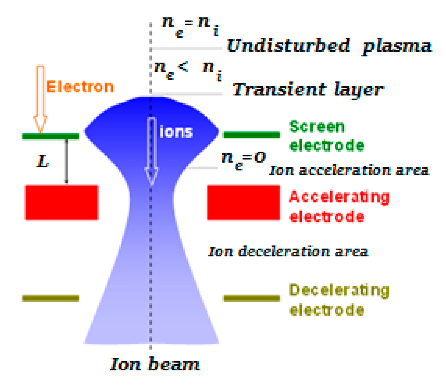
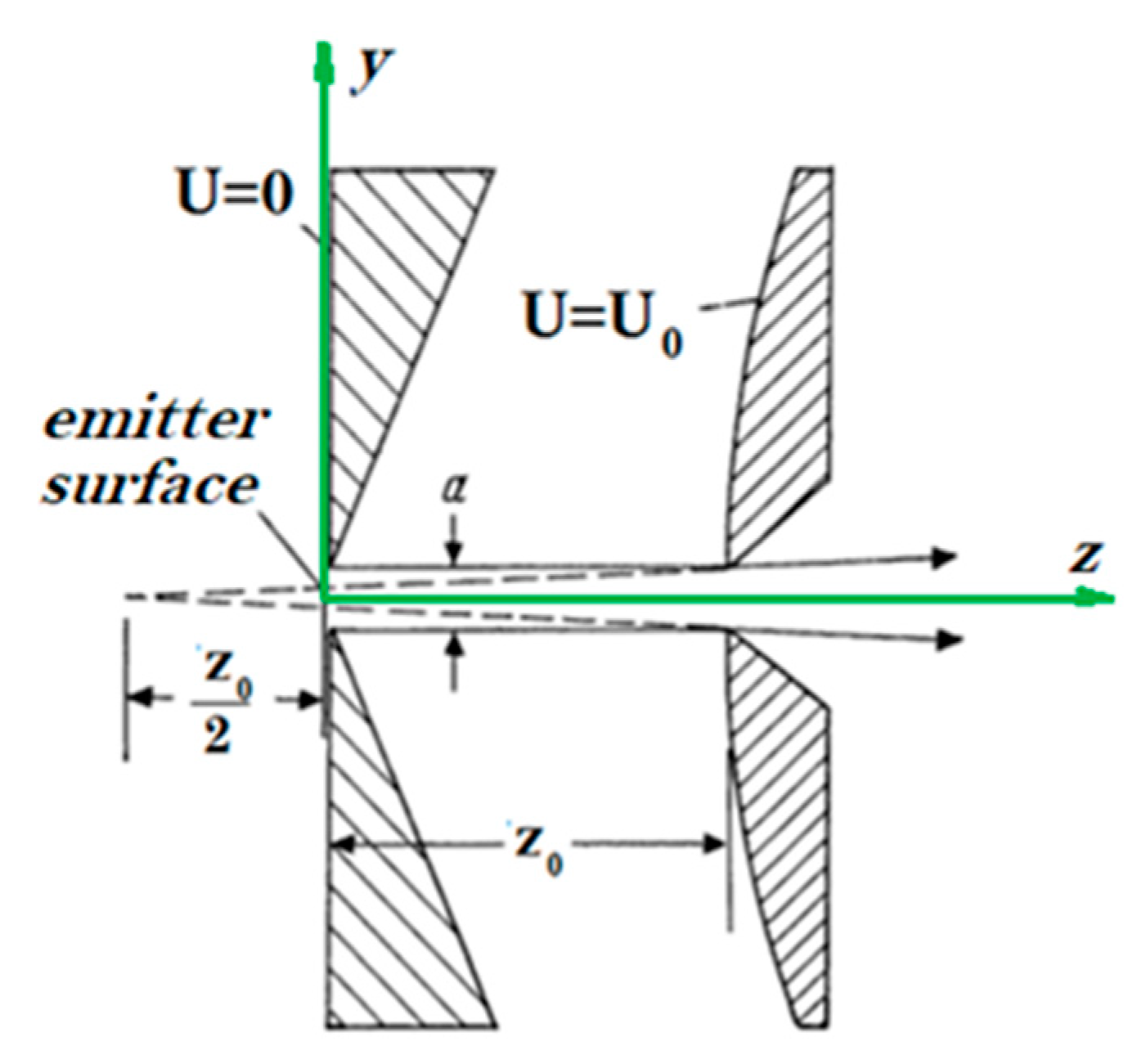
2.2. The Laminar Ion Beam Model

Electrodes with various hole (aperture) configurations are used to extract ion beams from plasma and to accelerate them. The electrode placed at the boundary of the GDC plasma and extracting ions out of the plasma volume, which is called a screen electrode (SE), is at a positive potential. Downstream, there is an electrode with a negative potential value, which is called an accelerating electrode (AE). The third electrode—a decelerating electrode (DE)—is optional, but it helps to focus the ion beam and partially resolves issues with the secondary ion fluxes generated as a result of ion charge exchange in the beam volume. A general layout of a three-electrode ES is shown in Figure 3.
It is necessary to generate an ion beam with high current density and low spatial divergence in order to force on SD. Let us determine the principles to select the design of electrodes that allow to obtain an ion beam with such characteristics.
The motion of ions in the flow is exclusively driven by the electrostatic field of the electrodes and by their interaction with other charged particles in the flow. Let us consider, in the first approximation, an ion flow without any admixture of other particles. For a one-dimensional case, parallel migration of ions can be supported by using electrodes in the form of infinite planes. The solution of such a classical problem was found by C.D. Child and refined by I. Langmuir [30]. The solution of the Poisson’s equation for the Child’s model problem gives the following density of the current in the beam, and this current density is the maximum possible:
j = 4 ε 0 9 2 e M U 3 2 L 2 = x U 3 2 L 2 ,
where U is the potential difference between SE and AE; L is the effective length of the accelerating gap (the distance between SE and AE); M is the propellant ion mass; e is the elementary electron charge; ε0 = 8.85 × 10⁻¹² F/m is the electrical permittivity of free space; x = 4 ε 0 9 2 e M is the Child’s constant.
The potential variation along the ion flow is U ( z ) = ( j x ) 2 3 z 4 3 , where z is the coordinate measured from the plasma boundary along the ion flow (Figure 4).
Further refinement of the problem regarding a parallel ion flow was carried out by J.R. Pierce [31], who has considered a beam for a two-dimensional case with the SE potential taken as the origin of the reference equal to zero. In this case, the potential distribution is as follows [32]:
U ( y , z ) = ( j x ) 2 3 ( y 2 + z 2 ) 2 3 cos ( 4 3 a r c t g ( z y ) ) .
where y is an axis perpendicular to the ion flow direction; U 0 = ( j x ) 2 3 z 0 4 3 is the potential at the plasma boundary; and z0 is the inter-electrode distance (Figure 4).
All equipotential lines at the beam edge are perpendicular to the ion motion direction and, up to a distance equal to z0, are well described by cylinders with a radius R = 3z0 [31,32]. This means that by placing electrodes under U and U0 potentials along the indicated lines, we will provide boundary conditions at the electrodes, under which the ions will move rectilinearly, even being at the beam edge. Therefore, Pierce proposed to use specially configured electrodes to create strip ion beams [32]. A wedge-shaped SE with a certain chamfer angle and a slit-type aperture configuration ensures formation of a parallel ion flow. Nevertheless, the AE output slit-type aperture acts like a spreading lens, diverging a beam. It is necessary that the distance z0 be much greater than the slit-type aperture width for an error of the Pierce’s approximate method to be insignificant. Ref. [32] proposes the z0/a ratio (Ref. to Figure 4) be of at least to four.
However, it is not sufficient to select the configuration of electrodes only; it is also necessary to select the potential difference for electrodes and the density of plasma, out of the volume of which the ions will be extracted. This selection should secure two factors: the velocity of outgoing ions and the configuration of the plasma emitter—the boundary, from which the ions start. In order to provide parallel ion flow, a flat plasma boundary is required from the SE side [32]. It is also possible to use a concave boundary configuration; then the ion beam will be converging.
Let us consider a beam injected by a slit-type aperture with the width a and length b (a << b). Under the influence of transverse field of the space charge, the ions stop moving in parallel and begin to diverge at increasing angles relative to the symmetry plane of the slit-type aperture as the distance from the SE increases (z coordinate).
With account of the slit-type aperture area, the beam current is as follows: I = j S = j a b = x U 3 2 a b L 2 .
The space charge effect on the beam motion is usually described using perveance: P = I U 3 2 = x a b L 2 . However, the best parameter for estimating the degree of influence of spatial charge and beam expansion is considered to be normalized perveance Π = I U 3 2 x b a [32], as a criterion for geometric similarity of an electrostatic accelerating system. Perveances in two geometrically similar systems operating with different plasma-forming gases differ by the square root of the ion mass ratio. The normalized perveance compares the efficiency of the electrode system with the maximum possible efficiency independent of the inter-electrode distance.
Ion beams are subject to divergence under the influence of their own space charge due to an ordinary electrostatic repulsion of positive ions. Action of electrostatic fields also leads to trapping of electrons and to rapid beam neutralization almost immediately downstream from the DE. As a result, the ions move through the plasma, which consists of the primary beam ions, secondary slow charge-exchange ions, and “thermalized” cold electrons. In this case, a radial drop of potential is established in the beam volume at the electron temperature level. Plasma is positively charged in the ion beam center, and ions will gradually escape outward as secondary ions are formed. Expansion of the beam is associated with a change of potential in the plasma and in the layer at the boundary. Beam expansion beyond that caused by angular spread occurs as a sequential separation of the outer layers of the beam, where the transition layer ions are located. The transverse expansion of the beam can be estimated as [32] y a = 1 2 + 1 18 Π ( z a ) 2 if we assume that there is no ion velocity spread in the ion beam and there are no other types of particles (collision-free motion).
Given the distances at which the ion beam should interact with space debris, it is necessary that the slit-type ES normalized perveance be significantly less than 1. For ensuring narrowness of the ion beam at a distance z to SD of about 40 m and the slit width a = 2 mm, the ES normalized perveance should be about 10−8.
In this case, the plasma beam actually contains monokinetic primary ions. Their energy spread does not exceed ±2%. The plasma beam structure was studied qualitatively in [33,34]. The experimentally obtained distributions of the ion beam energy as a function of the deviation angle from the thruster axis validated an inconsiderable energy spread. The profiles of current density for the propagating beam have a clear-cut symmetry and are fairly well described by the Gauss distribution [34].
Thus, it has been shown that it is possible to develop an electrode system generating a laminar monoenergetic and weakly diverging ion beam.

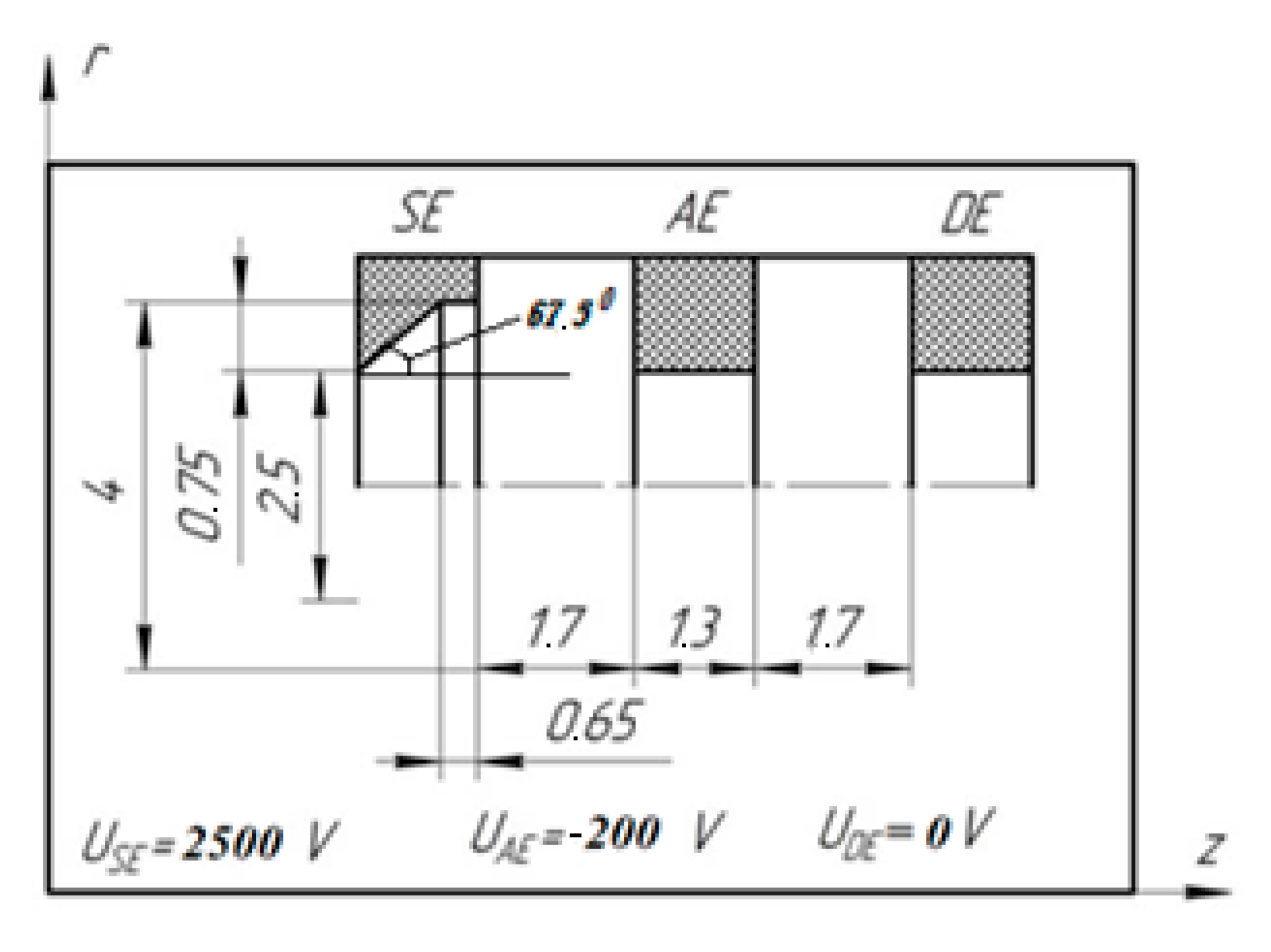
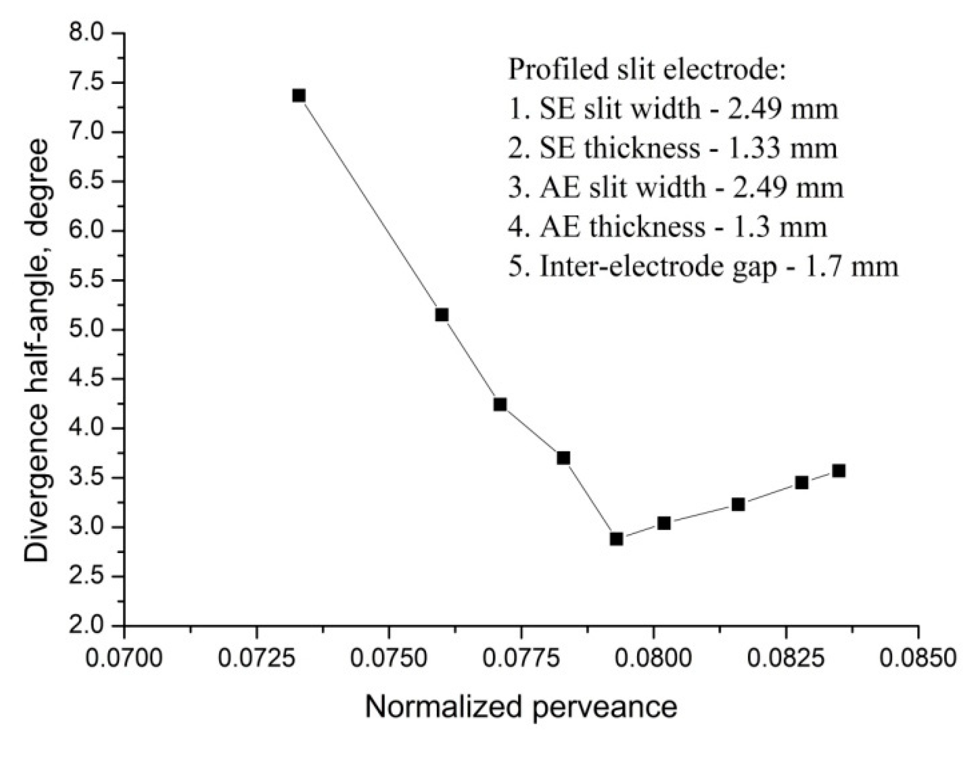
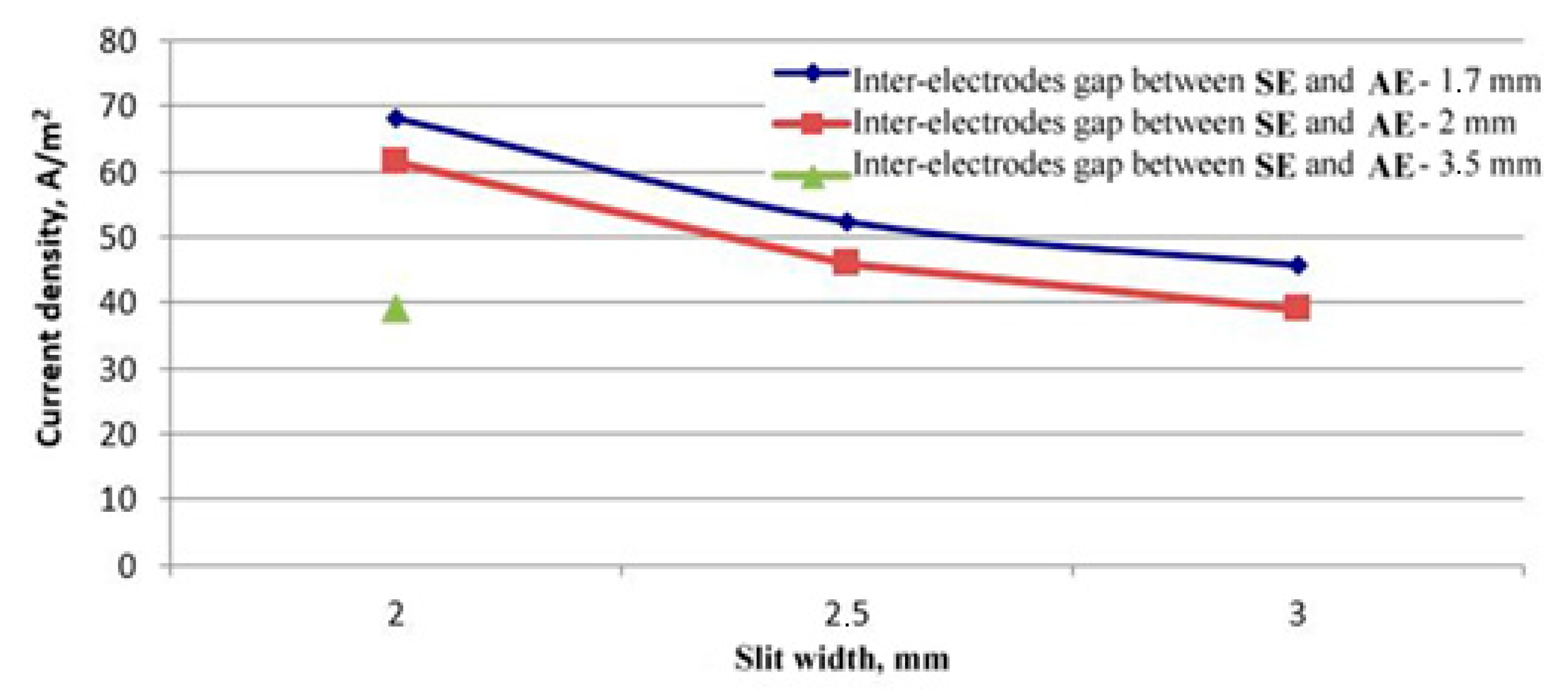
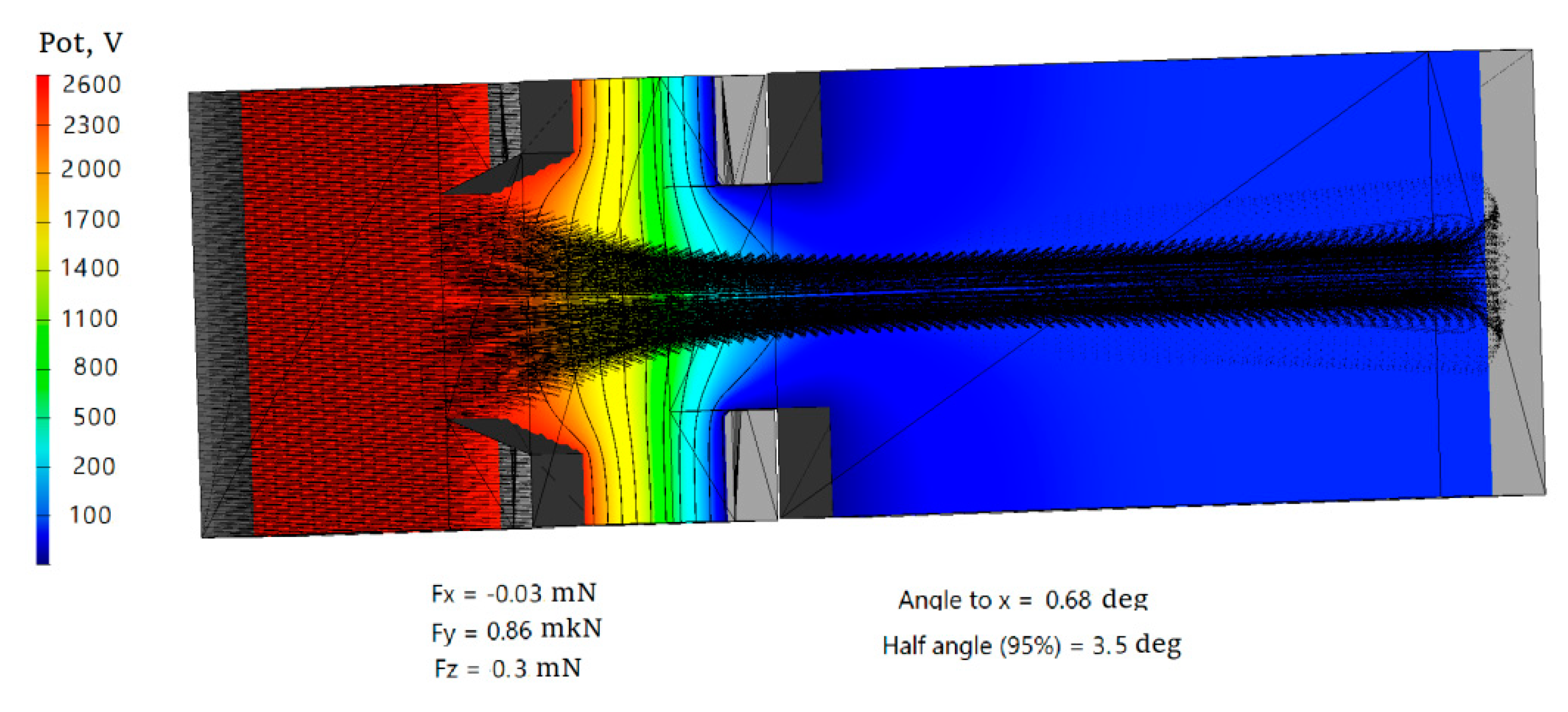
2.3. Simulation of ES with Slit-Type and Round-Type Apertures

A great number of apertures are used to obtain heavy current. Each aperture acts independently, i.e., the perveance and angular divergence for each aperture with a close-packed arrangement of the apertures are the same as in the case of a single aperture, as shown in [35]. Therefore, it is possible to simulate an electrode system with a single aperture.
A close-packed arrangement of the apertures in the SE surface is necessary to achieve high electrode transparency (to collect heavy current). Such a close-packed arrangement reduces the side space required for the electrodes with Pierce’s (or near-Pierce’s) geometry. It is also essential that the electrode systems of high-precision sources initially accelerate ions up to the energies higher than those required, and subsequently decelerate them down to a given energy level (the classical acceleration–deceleration concept). The reason for such operation principle is the need to suppress the back electron current to the source. The resulting equipotential surfaces are bent out (arched) towards the SE not only in the vicinity of the electrode itself, but also throughout the deceleration gap, which deteriorates the beam focusing. The third electrode (the decelerating electrode—DE) provides the occurrence of equipotential surfaces that contribute to beam focusing in the plasma neutralization region. Therefore, systems comprising three or more electrodes are always used to form beams with a narrow angular divergence. The third, decelerating, electrode is most often made circular, enveloping the entire beam, and this electrode is under the potential of the SSC body.
Therefore, it is proposed to force on space debris with an ion beam formed by a three-electrode slit-like ES using the classical ion flow acceleration–deceleration principle.
Requirements for the formation of an ion beam are driven by an estimated distance between the SSC and SD. Assuming 5 m as a baseline SD size, we obtain an estimate for the maximum distance, from which it is necessary to impact SD with an ion beam. This distance should not exceed 36 m (an impact area is estimated to be 20 m2 with an ion beam divergence angle of 4°). The required value of the ion beam divergence angle decreases as the distance between the SSC and SD increases. As a characteristic of the beam divergence, we use the divergence half-angle that is a half of the flat angle at the apex of the cone, inside which 95% of the ion beam current flows.
The peculiarity of the slit-type ES is that the beam divergence in the transverse direction relative to the slit occurs in accordance with the laws of electrostatics and can be varied by modifying the ES electrode design [32].
The ion beam divergence depends on the ratio between the thermal ion velocity and the accelerated ion velocity at the ES exit; the influence of the space charge of the beam and of the electron temperature in the neutralization zone is significant. Thus, the ion energy distribution measurements presented in [33] showed that the spread of ion energies in the beam can be as high as ±20 eV. We will take this value into account in order to assess the ion beam divergence.
In practice, the ES design is selected based on mathematical simulation methods. A sectional view of a single aperture of the electrode system is considered, and when taking into account the electric field symmetry, it is sufficient to analyze half of the ion beam. Such a single aperture is usually called as an ES elementary cell. A cell with selected electrode geometry (corresponding to Pierce’s electrodes in some approximation) is studied, and the perveance value is defined, at which the required ion beam geometry is achieved (in this case, with the minimum divergence). For the selected electrode potentials, the obtained perveance value is used to calculate the ion current density and plasma density needed to provide the required ion current density.
Like most of the plasma problems, the problem of primary ion beam generation is self-consistent. Mathematical simulation implements the following algorithms: calculating electrostatic fields by solving the Poisson equation iteratively, calculating the trajectories and space charge of charged particles in self-consistent electrostatic fields, modeling the extraction of positive ions out of plasma sources with a mobile plasma boundary, and calculating the flows and density of neutral particles with a free-molecular current with diffuse and mirror reflection from solid surfaces.
Essentially, the plasma boundaries are “traveling”; their location and shape are not known in advance. The shape of the plasma boundary can be flat or curved towards the GRC depending on the distribution of electrode potentials and plasma concentration in the GRC. Thus, their position is determined through an iterative process to solve the equation system, based on the condition that the electrostatic fields inside and outside the beam are consistent. A transient layer is established between undisturbed plasma and the plasma boundary in the SE aperture. The article [36] shows the results of mathematical modeling of the transient layer, confirmed by the results of experimental measurements. It has been shown that the length of the transition layer far exceeds the Debye length and is commensurate with the diameter of the hole in the emission electrode. There is also a “hole effect” in the layer. The curvature of the transient layer and its significant extent has a significant effect on the formation of motion paths of ions extracted from the plasma.
The value of plasma emitter potential is calculated on the basis of the double layer theory using the equation for the equality of the density of ion currents ji and the density of electron currents je when solving the self-consistent problem [36]: V p T e e ln ( 0.86 π m e M ) , where: me and Te are the mass and the temperature (in eV) of electrons, respectively. The analysis has shown that the plasma potential difference between the GDC and AE always exceeds the potential difference between the SE and AE by 20–30 V. This value corresponds to the potential of the plasma emitter, and therefore it is possible to estimate the electron temperature of about 5 eV. With respect to plasma, the SE is under a floating potential (USE). Therefore, the ES extracting (or throughput) capacity is defined by the potential difference: UES = USE + |UAE| + Vp.
Mathematical simulation was carried out in two stages. At the first stage, two-dimensional modeling was carried out using the IGUN software [37], which uses the simplest one-dimensional model of the transient plasma layer. This software allows you to conduct quickly a series of calculations to select the ES geometric parameters and the source plasma density to ensure the minimum divergence angle at the given electrode potentials. At the second stage, three-dimensional modeling is carried out with the selected parameters to refine and coordinate the design using the IOS-3D program [38].
  • Slit-Type ES Simulation
The temperature of electrons in the beam plasma was chosen to be 5 eV based on the results obtained in [34,35]. Plasma density is selected to ensure the minimum beam divergence. The shape of the SE profiling, AE parameters and inter-electrode gaps were varied. Best performances from the divergence angle perspective were obtained for a chamfered SE profile with a certain ratio for the triangle sides of the SE profile chamfer (Figure 5). In this case, the angle between the SE equipotential surface and the boundary of ion beam trajectories is close to the Pierce’s angle of 67.5°.
Dependence of the divergence half-angle on the ES normalized perveance was studied for the selected layout (Figure 6).
For such configuration, the current density is equal to 1.84 mA/cm2, taking into account the SE slit-type aperture width of 0.25 cm. With the plasma density of 0.70 × 1011 cm–3, the linear current density is 0.46 mA/cm, approximately, and the divergence half-angle is 2.9°. The energy of ions in the beam is about 2500 eV. The perveance is 8.1 × 10⁻¹⁰A/V3/2. The normalized perveance is 0.0793 taking into account the a/L (aspect) ratio. The velocity of ions (Xenon) is 56 km/s in this case.
The modeling was performed to study the influence of the inter-electrode gap (the SE-AE distance) and of the SE slit width on the ion beam current density (Figure 7) at the minimum divergence angle. It can be seen that the ion current density corresponding to the minimum beam divergence angle decreases with an increase in the SE slit width and in the inter-electrode gap. However, the inter-electrode gap widening reduces the ES breakdown probability.
Three-dimensional simulation was performed to check the correctness of the selected parameters of the slip-type electrode system. Simulation results of the distribution of the potential in the beam and of the ion trajectories are present in Figure 8.
A more thorough solution of the self-consistent problem, taking into account the transition layers, the space charge of the beam and collision processes, gives a slightly higher value of the divergence half-angle of 3.5°.
b
Experimental Results for Slit-Type ES
Tests of the slit-type electrode system were carried out, the parameters of which were selected based on the modeling results. The IS laboratory prototype (Figure 9) with the ES geometrical parameters presented in Table 1 have been tested with Xenon as a propellant (Figure 10). Table 2 shows basic experimental parameters, at which the minimum ion beam divergence angle for an IS with slit-type ES was obtained.
The above table shows parameters measured in the experiment and those calculated from the results of measurements: PRF is the radio-frequency generator (RFG) power, USE is the SE potential, ISE is the current in SE circuit, UAE is the AE potential, IAE is the current in AE circuit, Isp is the specific impulse, Ip is the beam current, Pi is the injector specific thrust, and W is the ion energy. In the experiment, two modes of an ion source operation were defined, close in parameters, which provide minimum half-angle of divergence. Accordingly, the second mode was tested by simulation. The following Table 3 compares simulation and experimental results.
c
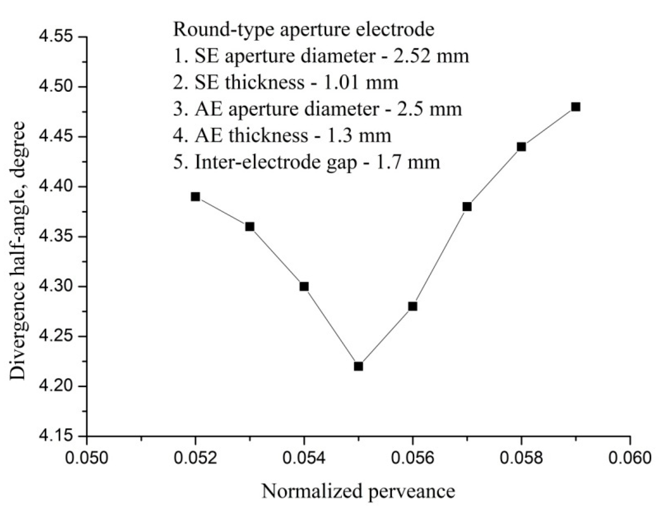
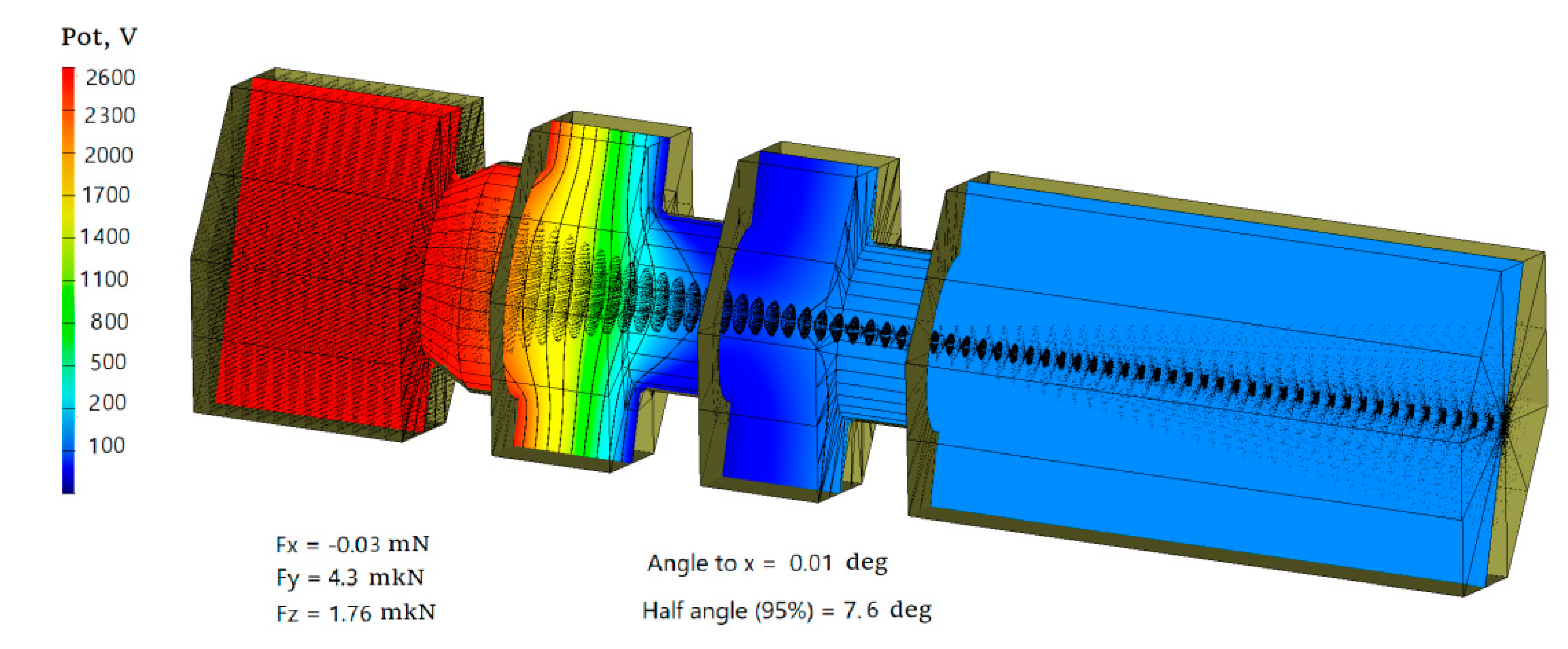
Simulation of ES with Round Apertures
Two-dimensional modeling for ES with round apertures was performed also. The angle between the SE equipotential surface and the ion beam boundary was selected close to the Pierce angle of 67.5°. That is, a quasi-Pierce geometry was used. The electrode geometry, electrode position and plasma density were selected to form a beam with minimal divergence. Figure 11 shows the selected electrode layout.
For the selected design, the divergence half-angle dependence on the normalized perveance was studied (Figure 12). For the optimal configuration, the current density is equal to 5.95 mA/cm2 with the plasma density of 0.97 × 1011 cm–3, and the half-angle of divergence is 4.22°. Energy of ions in the beam is 2800 eV approximately. The perveance is 2.05 × 10⁻⁹ A/V3/2. The normalized perveance is 0.061, if the aspect ratio π r 2 L 2 is taken into account, where the r is the hole radius and L is the distance between the electrodes.
3D simulations showed a slightly greater value of the divergence half-angle of 7.5°. The distribution of potential in the beam and ion trajectories are shown in Figure 13.
d
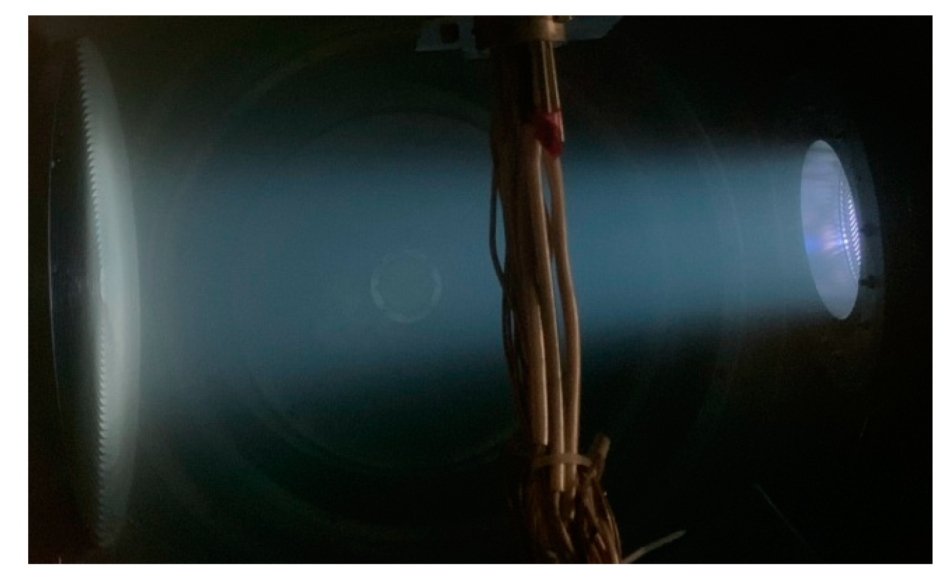
Experimental Results for ES with Round-Type Perforation
The IS laboratory model (Figure 14) with the ES geometrical parameters presented in Figure 11 has been tested with Xenon as propellant (Figure 15).
Table 4 shows basic experimental parameters of the ES mode, at which the minimum ion beam divergence angle for round-type perforated IS was obtained. There are also two modes that ensure the minimum divergence of the ion beam.
Table 5 shows the measured operation parameters, as well as those calculated on the basis of measurements: PRF is the radio-frequency generator power, USE is the SE potential, ISE is the current in SE circuit, UAE is the AE potential, IAE is the current in AE circuit, Isp is Table 5 compares simulation and experimental results for the selected IS configuration and the best modes specified above.

3. Conclusions

The possibility of forming an ion beam with low divergence and high specific impulse was experimentally confirmed.
If the geometric similarity of the ES electrodes is maintained, the transparency of electrodes with the round-type perforation is two times less than that of the electrodes with the slit-type perforation, but this fact did not lead to a proportional decrease in the extracted ion current for the modes with the corresponding minimum half-angle of ion beam divergence due to the higher density of the ion current. At that, IS with round-type perforation provides higher specific impulse and higher thrust at lower mass flow rates of working gas than the source with slot-type perforation (Table 2 and Table 4).
A comparison of ion beam parameters for ES with round-type and slit-type apertures validated the advantage of the slit-type ES. The divergence half-angle of the slit-type beam in the transverse direction is as low as 4.5°, whereas for the ES with round-type apertures, the beam divergence half-angle is uniform along the cone and is 7.5°. The limiting current value for the slit-type ES in the experiment was 0.41 A with the maximum SE voltage of 4000 V. For the IS with round-type aperture ES, the maximum voltage in experiment was 3300 V and the maximum current was 0.29 A.
It has been demonstrated that the conducted physical and mathematical simulation of the processes in the ES is in good agreement with the obtained experimental data. However, electrodes with slit-type apertures are modeled worse than those with round-type apertures. However, modeling allows us to identify a range of geometric and plasma parameters, ensuring that minimal beam divergence can be used to develop optimal ES designs for implementing the necessary engine parameters.
The optimum IS operation modes have been identified to ensure minimum divergence angles of the IS plasma beam, which in turn maximizes the pulse transmitted to the transported object.

Author Contributions

Conceptualization, methodology, validation, writing—review and editing, supervision, project administration, funding acquisition V.V.S., software, M.V.C., A.V.M. and O.D.P.; formal analysis, investigation, resources, data curation, writing—original draft preparation, visualization V.V.S., M.V.C., A.I.M., A.V.M. and O.D.P. All authors have read and agreed to the published version of the manuscript.

Funding

This work was supported by the Government of Russian Federation (Grant number 075-15-2019-1894).

Institutional Review Board Statement

Not applicable.

Informed Consent Statement

Not applicable.

Data Availability Statement

The data presented in this study are available on request from the corresponding author.

Acknowledgments

This research work was conducted in the Laboratory Space Flight Mechanics of the Moscow Aviation Institute.

Conflicts of Interest

The authors declare no conflict of interests.

Abbreviations

The following abbreviations are used in this manuscript:
AEaccelerating electrode
DEdecelerating electrode
ESextraction system
GDCgas discharge chamber
GEOgeostationary orbit
HFhigh-frequency
IESion-extraction system
ISion source
LEOlow Earth orbits
MEOmedium Earth orbits
RFradio-frequency
RFGradio-frequency generator
RITradio-frequency ion thruster
SCspacecraft
SDspace debris
SEscreen electrode
SOspace object
SSCservice spacecraft

Nomenclature

Indexes
AEindex of accelerating electrode parameter
ESindex of extraction system parameter
SEindex of screen electrode parameter
Parameters
awidth of the slit-type aperture
blength of the slit-type aperture
eelectron charge
IAEcurrent in AE circuit
ISEcurrent in SE circuit
Ipbeam current
Ispspecific impulse
jion current density
Lthe effective length of the accelerating gap (the distance between SE and AE)
memass of electrons
Mpropellant gas atom (ion) mass
Pperveance
Piinjector specific thrust
PRFradio-frequency generator power
Teelectron temperature (eV)
Upotential difference between SE and AE
UAEpotential of the acceleration electrode
UESpotential of the extraction system
USEpotential of the screen electrode
Vpfloating potential
Wion energy
xChild’s constant
yaxis perpendicular to the ion flow direction
zcoordinate measured from the plasma boundary along the ion flow
z0inter-electrode distance
ε0electrical permittivity of free space
Π normalized perveance

References

  1. Debus, T.J.; Dougherty, S.P. Overview and Performance of the Front-end Robotics Enabling Near-Term Demonstration (FREND) Robotic Arm. In Proceedings of the AIAA Infotech@Aerospace Conference, AIAA 2009–1870, Seattle, WA, USA, 6–9 April 2009. [Google Scholar]
  2. Kaiser, C.; Sjoberg, F.; Delcura, J.M.; Eilertsen, B. SMART-OLEV—An orbital life extension vehicle for servicing commercial spacecraft in GEO. Acta Astronaut. 2008, 63, 400–410. [Google Scholar] [CrossRef]
  3. Melamed, N.; Griffice, C.P.; Chobotov, V. Survey of GEO Debris Removal Concepts. In Proceedings of the 59th International Astronautical Congress, IAC–08–D4.1.8, Glasgow, UK, 29 September–3 October 2008. [Google Scholar]
  4. Bosse, A.B.; Brands, W.J.; Brown, M.A.; Creamer, G. SUMO: Spacecraft for the Universal Modification of Orbits. In Proceedings of the SPIE—The International Society for Optical Engineering, Orlando, FL, USA, 16 June 2004. [Google Scholar] [CrossRef]
  5. Norman, T.L.; Gaskin, D. Conceptual Design of an Orbital Debris Defense System, NASA-CR-197211. In Proceedings of the 10th Annual Summer Conference, NASA/USRA Advanced Space Design Program, Pasadena, CA, USA, 13 June 1994; p. 64. [Google Scholar]
  6. DLR. Institute of Robotics and Mechatronics. Close Space Robotics Missions. ROTEX (1988–1993). Available online: http://www.dlr.de/rm/en/desktopdefault.aspx/tabid-3827/5969_read-8744/ (accessed on 10 December 2020).
  7. DLR. Institute of Robotics and Mechatronics. Close Space Robotics Missions. Available online: http://www.dlr.de/rm/en/desktopdefault.aspx/tabid-3827/5969_read-8750/ (accessed on 10 December 2020).
  8. Murdoch, N.; Izzo, D.; Bombardelli, C.; Carnelli, I.; Hilgers, A.; Rodgers, D. Electrostatic Tractor for Near Earth Object Deflection. In Proceedings of the IAC-08-A.3.1.5, 59th International Astronautical Congress, Glasgow, UK, 29 September–3 October 2008; p. 11. [Google Scholar]
  9. Nishida, S.; Kawamoto, S.; Okawa, Y.; Terui, F.; Kitamura, S. Space debris removal system using a small satellite. Acta Astronaut. 2009, 65, 95–102. [Google Scholar] [CrossRef]
  10. Kawamoto, S.; Nishida, S.; Kibe, S. Research on a Space Debris Removal System, NAL Research Progress 2002–2003; p. 84–87, ISSN 1340-5977. Available online: https://repository.exst.jaxa.jp/dspace/bitstream/a-is/26112/1/nalrp2003000.pdf (accessed on 10 December 2019).
  11. Kaplan, M.H. Space Debris Realities and Removal. SOSTC Improving Space Operations Workshop Spacecraft Collision Avoidance and Co–Location; The Johns Hopkins University, Applied Physics Laboratory: Baltimore, MD, USA, 2010; p. 12. [Google Scholar]
  12. Starke, J.; Bischof, B.; Foth, W.-O.; Gunther, J.J. Roger a Potential Orbital Space Debris Removal System. In Proceedings of the 38th COSPAR Scientific Assembly, Bremen, Germany, 15–18 July 2010; p. 2. [Google Scholar]
  13. Bondarenko, S.G.; Lyagushin, S.F.; Shifri, G.A. Prospects of Using Lasers and Military Space Technology for Space Debris Removal, ESA-SP 393. In Proceeding of the 2nd European Conference on Space Debris, ESOC, Darmstadt, Germany, 17–19 March 1997; pp. 703–706. [Google Scholar]
  14. Raikunov, G.G. (Ed.) Space debris prevention. In Space Debris; FIZMATLIT: Moscow, Russia, 2014; Volume 2, p. 188. ISBN 978-5-9221-1504-9. (In Russian) [Google Scholar]
  15. Brown, I.; Lane, J.; Youngquist, R. A Lunar-Based Spacecraft Propulsion Concept—The Ion Beam Sail. Acta Astronaut. 2007, 60, 834–845. [Google Scholar] [CrossRef] [Green Version]
  16. Kitamura, S. Large Space Debris Reorbiter Using Ion Beam Irradiation. Paper IAC–10–A6.4.8. In Proceedings of the 61st International Astronautical Congress, Prague, Czech Republic, 27 September–1 October 2010. [Google Scholar]
  17. Bombardelli, C.; Peláez, J. Ion Beam Shepherd for Contactless Space Debris Removal. J. Guid. Control Dynamics. 2011, 34, 916–920. [Google Scholar] [CrossRef] [Green Version]
  18. Bombardelli, C.; Pelaez, J. Universidad Politecnica de Madrid. Sistema de Modificación de la Posicióny Actitud de Cuerpos en Órbita por Medio de Satélites Guía. ES Patent 2365394B2, 3 October 2011. [Google Scholar]
  19. NASAARES. Available online: https://orbitaldebris.jsc.nasa.gov (accessed on 10 December 2020).
  20. United Nations. General Assembly. Official records. 62 session. Supplement No. 20 (A/62/20). Report of the Committee on the Peaceful Uses of Outer Space. Available online: https://www.unoosa.org/pdf/gadocs/A_62_20E.pdf (accessed on 10 December 2019).
  21. NASA. Orbital Debris. Quarterly News. 2020.—V. 24, Is. 2. Available online: https://orbitaldebris.jsc.nasa.gov/quarterly-news/pdfs/odqnv24i2.pdf (accessed on 10 December 2020).
  22. Space Debris by the Numbers. ESA, January 2019. Retrieved 5 March 2019. Available online: https://www.esa.int/Safety_Security/Space_Debris/Space_debris_by_the_numbers (accessed on 10 December 2019).
  23. GEO Protected Region: ISON Capabilities to Provide Informational ISON Capabilities to Provide Informational Support for Tasks of Spacecraft Support for Tasks of Spacecraft Flight Safety and Space Debris Removal. 47session of the COPUOS STSC Session of the COPUOS STSC. 8–19 February 2010. Vienna. Available online: http://lfvn.astronomer.ru/report/0000059/Agapov_47sessionSTSC_2010.pdf (accessed on 10 December 2020).
  24. DeSelding, P.B. Space Station Required No Evasive Maneuvers in 2013 Despite Growing Debris Threat. SpaceNews. Available online: https://spacenews.com/39121space-station-required-no-evasive-maneuvers-in-2013-despite-growing-debris/ (accessed on 10 December 2020).
  25. Nadiradze, A.B.; Obukhov, V.A.; Popov, G.A.; Svotina, V.V. Modeling of Force Impact on Large-Sized Object of Space Debris by Ion Injection, IEPC-2015-66/ISTS-2015-b-66. In Proceedings of the Joint Conference of 30 ISTS, 34 IEPC, 6 NSAT, Kobe, Japan, 4–10 July 2015; p. 8. [Google Scholar]
  26. Balashov, V.V.; Cherkasova, M.V.; Kudryavtsev, A.V.; Masherov, P.E.; Mogulkin, A.I.; Obukhov, V.A.; Svotina, V.V.; Riaby, V.A.; Usovik, I.V. Radio Frequency Source of Weakly Expanding Wage-Shaped Xenon Ion Beam for Contactless Removal of Large-Sized Space Debris Objects. In Proceedings of the 7 European Conference on Space Debris, Darmstadt, Germany, 18–21 April 2017. [Google Scholar]
  27. Obukhov, V.A.; Pokryshkin, A.I.; Popov, G.A.; Svotina, V.V. Problems of the Method of Space Debris Objects Withdrawal by an Ion Beam. In Proceedings of the 7th Russian-German Conference on Electric Propulsion and Their Applications Electric Propulsion—New Challenges, Marburg, Germany, 21–26 October 2018. [Google Scholar]
  28. Certificate of state registration of the computer program No. 2018662928. In «Program for Simulating the Control of a Service Spacecraft with Non-Contact Means of Impact on Objects of Space Debris in the Process of Removal from the Protected Area of the Geostationary orbit. Disposeeso»/A.I. Pokryshkin (Russian Federation); Moscow Aviation Institute (National Research University): Moscow, Russia, 2018. (In Russian)
  29. Obukhov, V.A.; Kirillov, V.A.; Petukhov, V.G.; Popov, G.A.; Svotina, V.V.; Testoedov, N.A.; Usovik, I.V. Problematic issues of spacecraft development for contactless removal of space debris by ion beam. Act. Astronaut. 2021, 181, 569–578. [Google Scholar] [CrossRef]
  30. Langmuir, I. The Effect of Space Charge and Residual Gases on Thermionic Currents in High Vacuum. Phys. Rev. J. 1913, 2, 450–486. [Google Scholar] [CrossRef]
  31. Pierce, J.R. Theory and Design of Electron Beams; Van Nostrand: New York, NY, USA, 1954; p. 222. ISBN 978-1124091303. [Google Scholar]
  32. Forrester, A.T. Large Ion Beams, Fundamentals of Generation and Propagation, 1st ed.; John Wiley and Sons Inc.: Hoboken, NJ, USA, 1987; 325p, ISBN -0-471-62557-4. [Google Scholar]
  33. Bundesmann, C.; Tartz, M.; Scholze, F.; Neumann, H.; Leiter, H.J.; Scortecci, F.; Feili, D. In-Situ Temperature, Grid Curvature, Erosion, Beam and Plasma Characterization of a Gridded Ion Thruster RIT-22, IEPC-2009-160. In Proceedings of the 31st International Electric Propulsion Conference, Ann Arbor, MI, USA, 20–24 September 2009; p. 10. [Google Scholar]
  34. Snyder, J.; Goebel, D.M.; Hofer, R.R.; Polk, J.E.; Wallace, N.C.; Simpson, H. Performance Evaluation of T6 Ion Engine. J. Propuls. Power 2012, 28, 371–379. [Google Scholar] [CrossRef]
  35. Cooper, W.S.; Berkner, K.H.; Pyle, R.V. Multiple-Aperture Extractor Design for Producing Intense Ion and Neutral Beams. Nucl. Fusion 1972, 12, 263–265. [Google Scholar] [CrossRef]
  36. Obukhov, V.A.; Sosnovsky, V.E. Calculation of the transition layer in the emission hole of a gas-discharge ion source. In Proceedings of the 5th All-union Conference on Plasma Accelerators and Ion Injectors, Moscow, Russia, 19–22 October 1982; pp. 105–106. (In Russian). [Google Scholar]
  37. Becker, R. Modeling of Extraction of Positive Ions from Plasma IGUN (1997–2011). Available online: www.egun_igun.com (accessed on 20 December 2019).
  38. Certificate of State Registration of the Computer Program No. 2014610277. In «Modeling of Charged Particle Flows in Ion-Optical Systems of Ion Thrusters (IOS-3D)»/A.A. Shagayda (Russian Federation); Keldysh Research Center: Moscow, Russia, 20 April 2014. (In Russian)
Figure 1. Number of space objects in near-Earth orbits (LEO—Low Earth orbits; MEO—Medium Earth orbits; GEO—Geostationary Orbit) as a function of the year from 1956 to 2020.
Aerospace 08 00276 g001
Figure 2. Radio-frequency ion thruster—Basic configuration (see text for more details).
Aerospace 08 00276 g002
Figure 3. Location of Electrodes in the IS—General Layout.
Aerospace 08 00276 g003
Figure 4. Geometry of Pierce’s electrodes [32].
Aerospace 08 00276 g004
Figure 5. Optimal layout—configuration and location of electrodes with slit-type apertures (geometric parameters are presented in millimeters).
Aerospace 08 00276 g005
Figure 6. Divergence half-angle as a function of slit-type ES normalized perveance.
Aerospace 08 00276 g006
Figure 7. Ion current density as a function of slit width for the inter-electrode gap of 1.7 mm, 2 mm and 3.5 mm at the minimum divergence angle.
Aerospace 08 00276 g007
Figure 8. Distribution of Potentials in the Cell of ES with Slit-Type Perforation.
Aerospace 08 00276 g008
Figure 9. ES with Slit-Type Perforation.
Aerospace 08 00276 g009
Figure 10. Operating IS with Slit-Type ES.
Aerospace 08 00276 g010
Figure 11. Optimal layout—configuration and location of electrodes with round holes.
Aerospace 08 00276 g011
Figure 12. The divergence half-angle as a function of perforated ES normalized perveance.
Aerospace 08 00276 g012
Figure 13. Distribution of Potentials in the Cell of ES with Round-Type Perforation.
Aerospace 08 00276 g013
Figure 14. IS with Round-Type Perforation.
Aerospace 08 00276 g014
Figure 15. Operating IS with Round-Type Perforation.
Aerospace 08 00276 g015
Table 1. Parameters of the Slit-Type ES.
ParameterValue (Test 1)Value (Test 2)
AE slit width, mm2.492.49
SE slit width, mm2.492.49
Inter-electrode gap, mm1.71.7
SE thickness, mm1.331.33
AE thickness, mm1.31.3
SE potential, V25003000
AE potential, V–200–300
Table 2. Experimental results for IS with slit-type perforation with minimal divergence of the ion beam.
Measured ParametersCalculated, Based on the
Experiment
Mass flow rate, mg/sPRF,
W
USE,
V
ISE,
A
UAE,
V
IAE,
A
Isp,
sec
Ip,
A
Pi,
mN
W,
keV
0.77122025000.1902000.00120830.1816.02.50
0.94723530000.2803000.01027370.2725.973.00
Table 3. Comparison of experimental and simulation results for a slit-type ES providing minimal beam divergence.
ParameterExperimental ResultSimulation Result
SE potential, V25002500
AE potential, V–200–200
Ion current, A0.190.15
Perveance, A/kV3/20.0430.034
Inter-electrode electric field intensity, kV/mm1.591.59
SE potential, V30003000
AE potential, V–300–300
Ion current, A0.280.21
Perveance, A/kV3/20.0470.035
Inter-electrode electric field intensity, kV/mm1.941.94
Table 4. Experimental results for IS with round-type perforation providing minimal ion beam divergence.
Measured ParametersCalculated, Based on the
Experiment
Mass flow rate, mg/sPRF,
W
USE,
V
ISE,
A
UAE,
V
IAE,
A
Isp,
s
Ip,
A
Pi,
mN
W,
keV
0.56123025000.2043000.005030730.20417.42.50
0.73227030000.2853000.007536040.28526.43.00
Table 5. Parameters of the IS ES with Round-Type Perforation providing minimal beam divergence.
ParameterExperimental
Result
Simulation Result
SE potential, V25002500
AE potential, V–300–300
Ion current, A0.2040.210
Perveance, A/kV3/20.0440.045
Inter-electrode electric field intensity, kV/mm1.651.65
SE potential, V30003000
AE potential, V–300–300
Ion current, A0.2850.245
Perveance, A/kV3/20.0480.041
Inter-electrode electric field intensity, kV/mm1.941.94
Publisher’s Note: MDPI stays neutral with regard to jurisdictional claims in published maps and institutional affiliations.

