Abstract
Equipped with a distributed electric propulsion system, eVTOL is the primary vehicle for future urban air mobility. The electrical machine determines the weight of the distributed electric propulsion system, and the cooling capability determines the electrical machine’s weight. The electrical machine with air cooling is preferred for eVTOL due to its simplicity and light weight. This paper presents a new air-cooling system for an electrical machine in an electric ducted fan propulsion system. The novel cooling system consists of a cooling guide vane with a heat pipe (CGVHP), which is located downstream of the ducted fan rotating blade. The heated end of the heat pipe is inserted into the stator end windings and the cold end is inserted into the cooling guide vane. The heat generated in the windings is transmitted to the cooling guide vane by the heat pipe and dissipated by the forced convection using low-temperature air passing through the ducted fan. The cooling performance of the cooling guide vane with the heat pipe was numerically simulated, considering several critical design factors. The simulation results showed that the proposed CGVHP can be helpful for reducing the winding temperature of the electrical machine by over 25.5 °C at the peak power condition of 15.7 kW.
1. Introduction
Urban air mobility (UAM) has become the focus of the transportation industry in recent years due to its ability to carry passengers to their destination quickly, safely, and with low emissions [1,2]. The advantages of UAM provide great potential for the development of electric flying cars, a key vehicle that could be used to satisfy the needs of UAM, with an immense market size, and deployment of the electric flying cars in the future. Morgan Stanley predicted that the market capacity of the whole UAM production around the whole world will reach 1 trillion in 2040 [3]. Roland Berger predicted that there will be over 5000 electric flying cars in 2030 [4]. To date, there over 300 programs developing electric flying cars have been initiated around the world.
Among the electric flying cars under development, the electric ducted fan (EDF) is a suitable propulsor for a distributed electric propulsion system because of its high aerodynamic efficiency, quietness, and safety [5,6,7], which are essential for the ability of electric flying cars to operate in downtown business districts or residential areas. Among all the electric flying car projects, Lilium and e.SAT are well known for utilizing the EDF technologies in their vehicles [8,9,10].
To achieve the long endurance of flying cars, an EDF with a high power density is essential. The main components of the EDF are the fan blades, the duct body, and the electrical machine. The fan blades are usually driven by an electrical machine directly, and their speed–torque profiles are closely coupled and matched. Among these components, the fan blade and duct are usually manufactured using carbon fiber composites which are lightweight. The electrical machine is manufactured using copper, silicon steel, and aluminum alloy, etc., which are heavy, especially under high-power conditions. Therefore, the electrical machine accounts for a large proportion of the weight of the EDF. The power density of the electrical machine needs to be improved in order to reduce the weight of the EDF and to improve the thrust-to-weight ratio of the fan.
The main methods of increasing the power density of electrical machine are the innovation of the electromagnetic designs [11,12], the application of novel electromagnetic materials [13,14], and novel thermal management technologies [15,16]. However, in EDFs, due to the limited space for the cooling systems and the high reliability requirements, forced air cooling is preferred for the electrical machine. In [17], Jin.et al. pointed out that the matching design method cannot achieve the optimal power density of the EDF if the thermal management is not fully considered. Due to the poor air flow performance on the surface of the hub region, a larger diameter of the hub region is usually required to provide a sufficient heat transfer area in order to mitigate the heat loss generated by electrical machines. A self-pumped air cooling design for a high frequency electrical machine in boundary layer ingestion fan propulsor was designed by Yi et al. [18,19]. The aggressive air cooling design allows for a level of electric loading typically associated with liquid cooling, which enables a power density of 13 kW/kg at a power level of 1 MW. In [20], a high performance cooling system based on heat pipe technology was proposed for an outer rotor electrical machine with a maximum power of 60 kW. A power density of 4.24 kW/kg and torque density of 17.6 Nm/kg was achieved through the cooling system. In [21], Wei Le et al. measured the relationship between the thermal performance of a heat pipe with temperature and proposed a novel stator cooling structure that utilizes the heat pipe. Computational fluid dynamic simulation verified that the proposed cooling structure is capable of removing the heat from the stator and reducing the temperature rise in the stator. In [22], in order to solve the serious problem of the temperature rise in slot winding, a new winding cooling technique, designed by inserting the heat pipe into the center of the slots, was proposed by Geng et al. The current density of the coils under long-term operation reached 15 A/mm2. From the abovementioned studies, we can see that there is great potential to improve the power density of air-cooled electrical machines in EDFs by solving the thermal problems through utilizing the heat pipes.
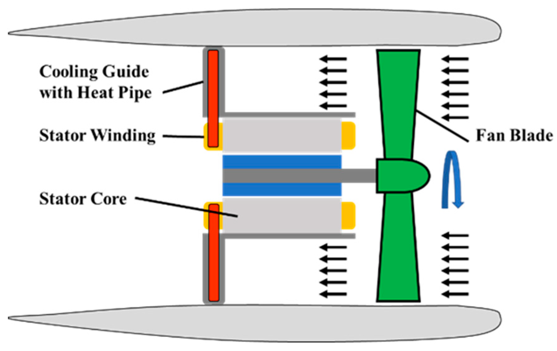
The goal of this paper is to propose a novel concept of a cooling guide vane with a heat pipe (CGVHP) in an EDF and to evaluate the thermal performance of the proposed CGVHP for an electrical machine in the EDF by applying numerical simulations. The proposed cooling mechanism of the proposed design is shown in Figure 1. The results show that both the thermal performance and power density of the electrical machine can be improved with the proposed CGVHP. In Section 2, a cooling concept for the thermal management of the electrical machine of the CGVHP in the EDF is proposed. Section 3 presents the preliminary design of the CGVHP. In Section 4, the built CFD model is evaluated with respect to the thermal performance of the proposed CGVHP. The results are discussed in Section 5. Finally, Section 6 concludes the article.
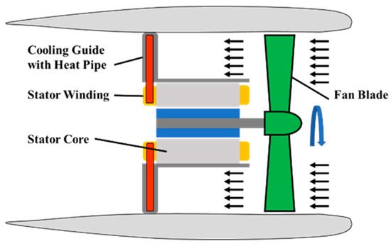
Figure 1.
Cooling Mechanism of The Proposed Design.
2. Proposed Cooling Guide Vane with a Heat Pipe for an Electrical Machine in an EDF
Today, the EDF is widely used in several flying vehicles due to its high propulsion efficiency, high safety, and low noise during operation. In the EDF, the fan blades are driven by an electrical machine and compress the air to provide the thrust force. Similar to the turbofan engine, the hub-to-tip ratio of the EDF influences the propulsion efficiency by affecting the aerodynamic performance of the ducted fan [23]. In order to maintain a high propulsion efficiency, the hub-to-tip ratio should be selected to be as small as possible. However, in a direct hub-driven fan, the hub-to-tip ratio constrains the diameter of the electrical machine, which is a critical parameter for torque generation in the electromagnetic aspect and also the heat dissipation aera in the thermal management aspect. Therefore, the power density of the electrical machine is diminished when a small hub ratio is chosen during the aerodynamic design of the ducted fan. Efficient thermal management technology may provide one of the effective means of improving the power density of the electrical machine.
In regard to the proposed EDF, one of the objectives is to achieve a high power density of the electrical machine using efficient thermal management technology. In the creation of the proposed design, a CGVHP was specially designed for the air-cooling system of the electrical machine. The CGVHP plays important roles in three aspects. Firstly, from the perspective of the thermal design, the CGVHP acts as the main cooling part of the electrical machine. Secondly, the CGVHP provides the structural support for the center-mounted electrical machine and fan blade, which is vital for the safe operation of the ducted fan. Last but not least, from the perspective of the aerodynamic design, the cooling guide vane acts as the stator vane, which recovers kinetic energy from the swirling flow and, consequently, a propulsion efficiency improvement is obtained. One of the major benefits of this proposed design is that the mass of the structural support is reduced by the functional reuse of the CGVHP. The value of the CGVHP in the circumferential direction depends on the structural and aerodynamic-thermal constraints of the EDF. In the case study explored in this paper, a total of 12 CGVHPs were equally spaced at the stator of the electrical machine in the circumferential direction.
The cooling mechanism of the proposed CGVHP can be described as shown in Figure 2. In this design of the proposed CGVHP, the heat pipe was selected to transmit the heat from the copper loss in the stator windings to the cooling guide vane due to its high heat flux capacity [24]. Therefore, an additional heat dissipation path for the stator winding was established between the stator end windings and cooling air flow through the proposed CGVHP. The temperature of the stator end windings is reduced, and the continuous output power of electrical machine is improved, as is the power density of the electrical machine.

Figure 2.
EDF with CGVHPs.2.1. EDF as a Case Study.
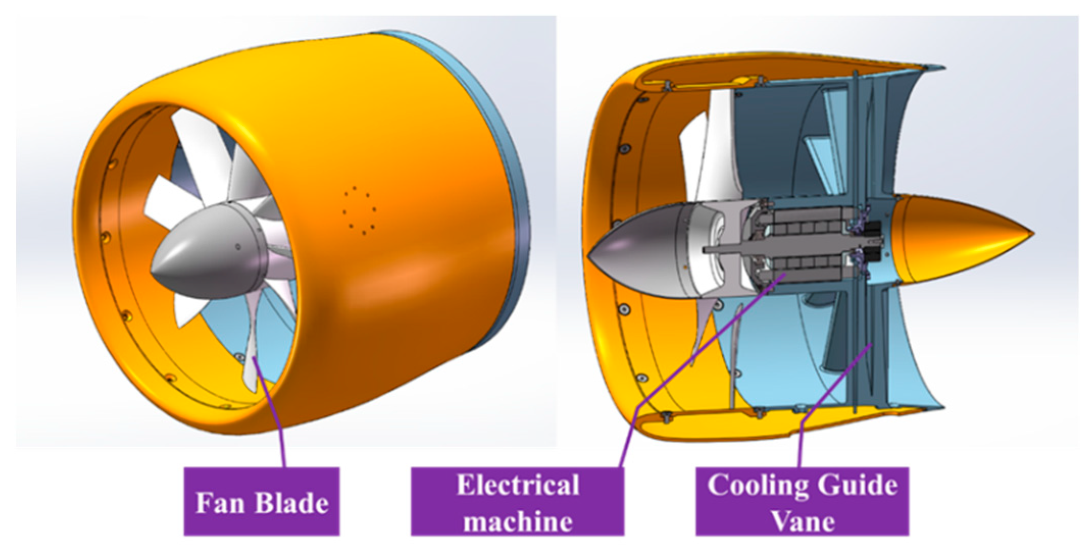
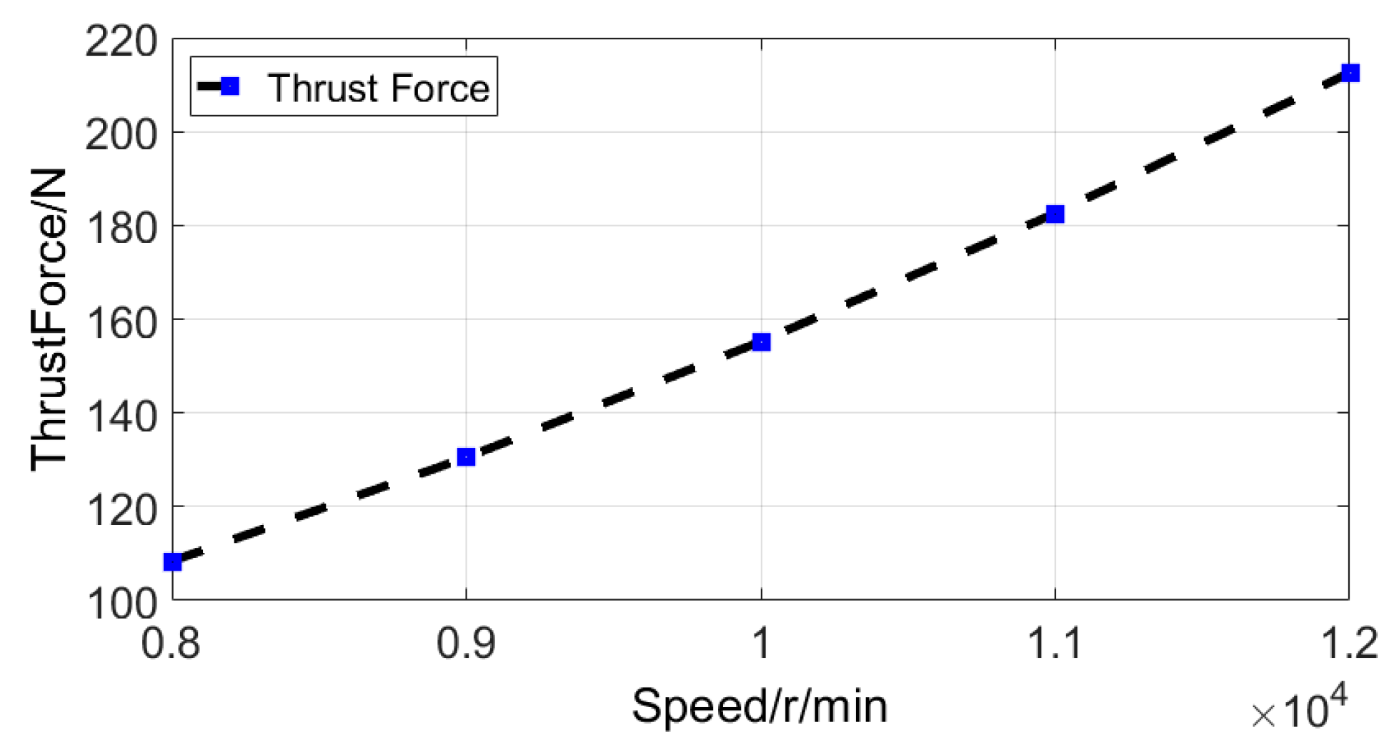
To validate the thermal benefits of the proposed CGVHP for electrical machines, an EDF, based on a prototype eVTOL, was used as a case study. The weight of the prototype eVTOL was 100 kg, and 6 EDFs with the proposed CGVHP were used to provide the required thrust for the vertical take-off process. Taking the safety margin into consideration, the thrust force of each EDF was 220 N. Table 1 lists the corresponding EDF specifications. The EDF, with the ducted fan, electrical machine, and cooling guide vane, is shown in Figure 3. An aerodynamic analysis using ANSYS-CFX was carried out to obtain the thrust force and fan rotor torque. The corresponding thrust force and torque, with the fan speed, are shown in Figure 3 and Figure 4. This data sheet provided the input for the later thermal designs of the proposed CGVHP.

Table 1.
The EDF Specification.
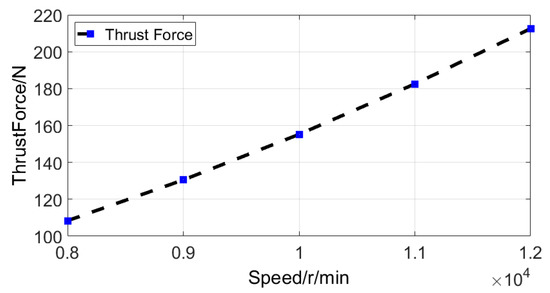
Figure 3.
Ducted fan thrust force.
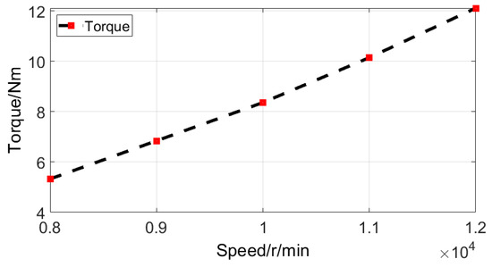
Figure 4.
Ducted fan rotor torque.
Electrical Machine Used in an EDF
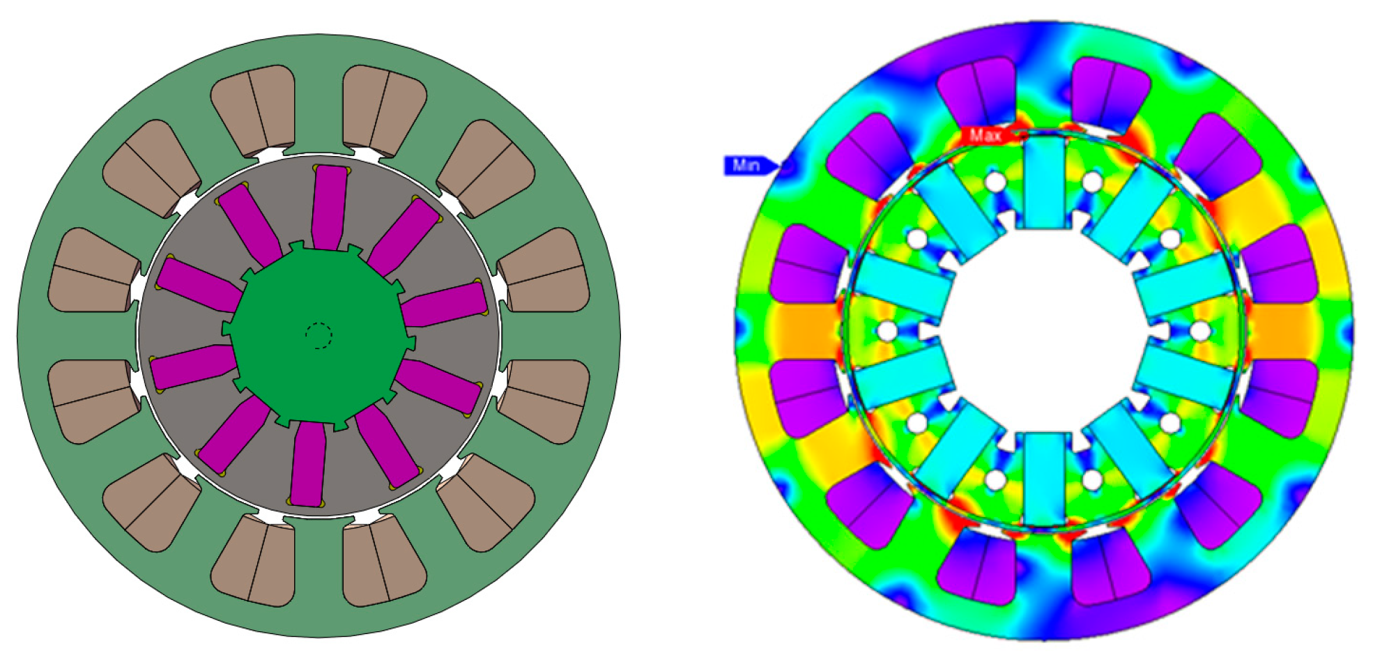
The CGVHP enables a higher power density of the electric machine to be obtained because it is in direct thermal contact with the end windings. Therefore, a lower thermal resistance and a higher continuous current density are enabled. The goal of the electrical machine design is to achieve a continuous output power density of 8.9 kW/kg (active mass only) under forced air cooling conditions. A high-power-density electrical machine is designed, for reference, as a 10-pole, 12-slot radial flux machine with double layer winding, and a spoke-type rotor configuration is selected [25]. The cross section view and magnetic flux distribution of the electrical machine under no-load condition is shown in Figure 5. The heat pipe is inserted into the end windings between two coils. The machine’s basic specification parameters are presented in Table 2. The chosen electrical machine design has the following beneficial features:

Figure 5.
Cross-Section View of the Electrical Machine.
Table 2.
The Electrical Machine Specification.
- (1)
- Winding: a concentrated winding wound around one stator tooth, which has a higher slot fill factor, and a short end winding. The space between the two adjacent tooth coils is beneficial for the installation of the heat pipe.
- (2)
- Rotor: the magnet flux concentration topology enables a higher air gap flux density, which is beneficial for a higher power density.
- (3)
- Torque: the low cogging torque and torque ripple caused by the 10/12 slot/pole combination ensures the smooth operation of the fan blades with low vibrations.
3. Preliminary Design of the CGVHP
3.1. CGVHP Cooling System Design
In the proposed EDF, the cooling system of the electrical machine features two heat transfer pathways, namely the CGVHP cooling and the traditional electrical machine housing cooling, which are designed for the electrical machine. For the CGVHP cooling, the heated end of the heat pipe is embedded in the stator end windings in order to absorb the heat generated in the stator winding, and the cold end of the heat pipe is inserted into the cooling guide vane to increase the heat convection area, as depicted in Figure 1 and Figure 2. The thermal load is generated in the stator windings when the electrical machine drives the ducted fan blades and is then transmitted to the cooling guide vane by the heat pipe. An isometric view of a thermal unit is shown in Figure 6. It is composed of two stator winding coils wound around two adjacent stator teeth, one heat pipe, and a cooling guide vane.
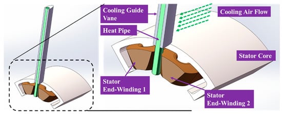
Figure 6.
CGVHP Cooling System Composition.
3.2. Cooling Guide Vane
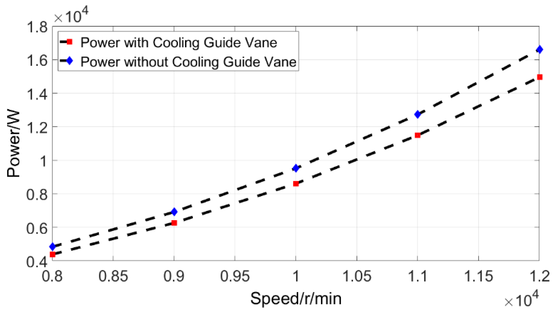
Similar to the turbofan engine, the cooling guide vane is the stationary blade which transfers the kinetic energy from the swirling flow into pressure. Therefore, the aerodynamic design of the cooling guide vane should be carefully considered. In the proposed design, the cooling guide vane provides not only the aerodynamic function of the ducted fan, but it is also the heat dissipation part of the electrical machine in the EDF. Consequently, in the design of the cooling guide vane, there is a coupling effect between the thermal performance and aerodynamic performance. Since this paper is primarily focused on evaluating the improvement of the thermal performance of the proposed CGVHP in the EDF, a detailed aerodynamic analysis of the cooling guide vane is considered beyond its scope. However, by comparing the EDF’s performance with and without the cooling guide vane, we can see that the CFD results show that the cooling guide vane can be helpful in reducing the power consumption of he ducted fan while maintaining the thrust force at the same level. A comparison of the power consumption and thrust force of the EDF with and without the cooling guide vane is shown in Figure 7. It shows that with the help of the cooling guide vane, the power consumption of the fan decreases from 16.595 kW to 14.95 kW at 12,000 r/min, so that the fan saves 1.645 kW and, consequently, the fan propulsion efficiency is improved.
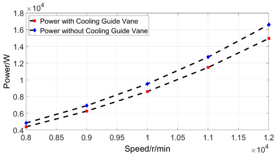
Figure 7.
Power consumption of the EDF with and without the cooling guide vane.
In the thermal design of the cooling guide vane, the thermal resistance of the convection process is calculated by:
where h is the heat transfer coefficient of the convection process and A is the convection area of the cooling guide vane. The units for the thermal resistance, heat transfer coefficient of the convection process, and the convection area are K/W, W/m2K, and m2, respectively. From the thermal management perspective, in order to achieve a lower thermal resistance, the cooling guide vane requires a large surface area and high heat transfer coefficient, which can be enhanced by simply increasing the air velocity or through specific surface treatment techniques, such as pin-fin arrays. In the proposed EDF, the cooling air flow is accelerated by the fan blade. The accelerated velocity contributes to the enhancement of the heat transfer coefficient. In a cooling guide vane, the convection area is mainly affected by the height and the chord length. The increase in the heat transfer coefficient and the convection area reduces the thermal resistance of the convection process and, thus, a lower temperature rise is achieved in the stator winding.
3.3. Heat Pipe Utilization and Modeling
In the proposed CGVHP, the heat pipe is used to transmit the heat in the stator winding to the cooling guide. Apart from the heat exchange surface between the heat pipe and stator end windings, the heat transfer capability of the heat pipe depends on the thermal conductivity coefficient. In fact, a series of materials with a high thermal conductivity can be used to transfer the heat in stator winding. Table 3 lists the potential materials with their respective thermal conductivity values.
Table 3.
Thermal Conductivity of the Potential Material to Transfer Heat.
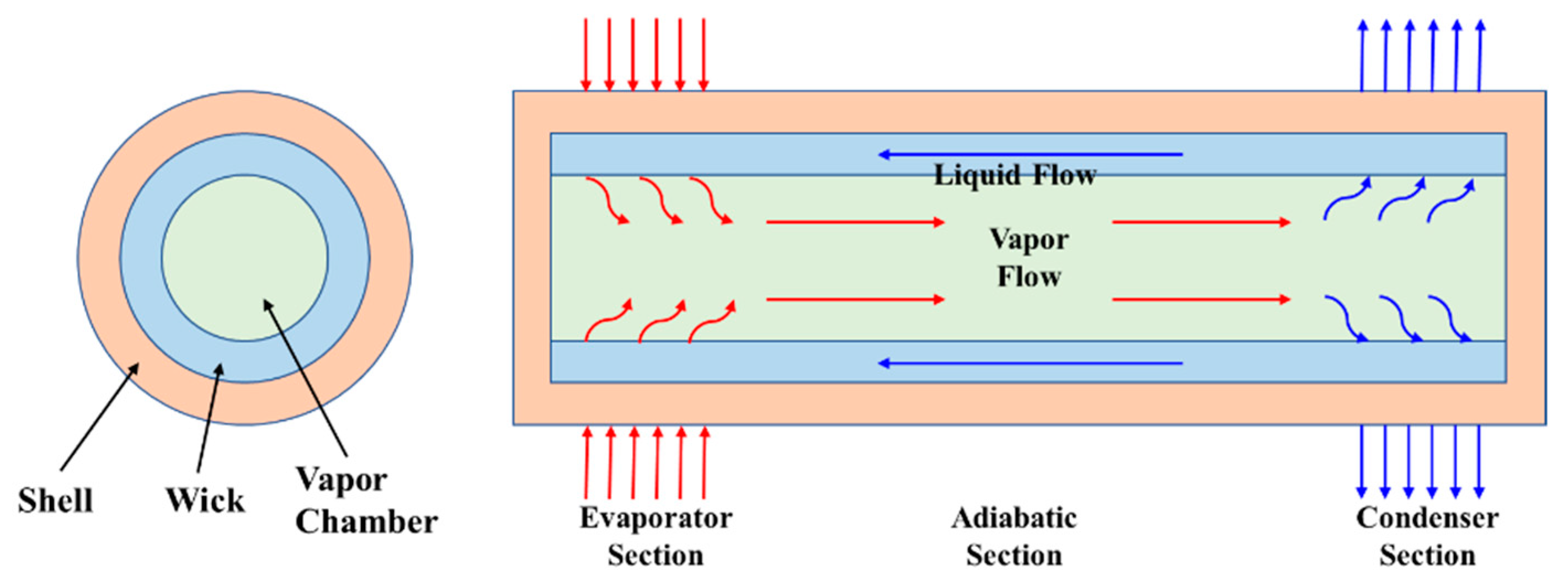
Among these materials, the heat pipe is an efficient type of heat transfer device that has been adopted in the design of electrical machines in some studies and inventions [26,27]. The thermal conductivity of heat pipes can reach 104 W/mK, far exceeding that of the common thermal conductive materials. Therefore, the heat pipe is selected according to the material. Figure 8 shows the working principle of the heat pipe [28]. A heat pipe is a tube filled by a working fluid in a saturated state, which mainly includes three parts, namely, an evaporator section, adiabatic section, and condenser section. When the evaporator section is heated up, vapor is generated and carries the heat to the condenser section, where the heat pipe is cooled through the convection process. Then, the working fluid turns from a vaporous state back to a fluid state and flows back to the evaporator section, driven by the capillary forces. Therefore, the process works continuously when the evaporator section is heated up and the condenser section is cooled down.

Figure 8.
Working principle of the heat pipe.
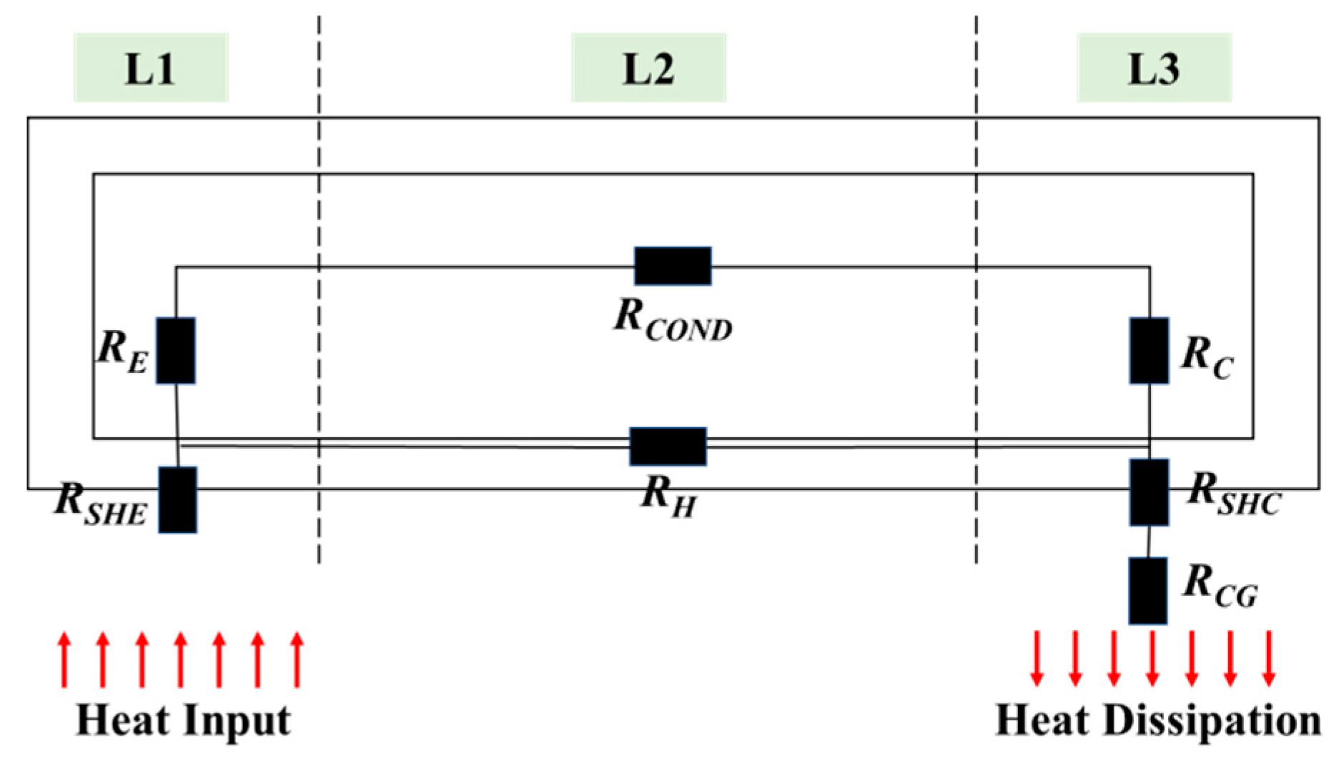
As the numerical simulation of a heat pipe is usually time-consuming and complex in terms of the calculations due to the complicated heat transfer mechanism, a simplified equivalent thermal resistance network model of a tubular heat pipe with a high accuracy is established to access the thermal performance of the heat pipe [29,30]. By analyzing the working principle of the heat pipe, we can see that the equivalent thermal resistance of the heat pipe can be divided into seven parts, as shown in Figure 9. In the thermal model, at the evaporator section, the thermal resistance from the shell wall to the vapor chamber can be divided into four parts: (1) the thermal conduction resistance RSHE of the shell wall; (2) the thermal conduction resistance RGR of the grove structure; (3) the thermal conduction resistance RSP of the supporting column; and (4) the thermal resistance RE due to the phase change in the evaporation process. The heat transfer process at the condenser section is similar to the process at evaporator section.
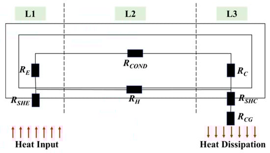
Figure 9.
Equivalent Thermal Resistance of The Heat Pipe.
The RSHE and RSHC, representing the thermal resistance of the shell wall at the evaporator and condenser sections, respectively, are:
where d3 and d4 are the outer and inner diameters of the heat pipe, whose unit is m, and λ2 is the thermal conductivity of the heat pipe shell, whose unit is W/mK.
The RC and RE, representing the thermal resistance due to the phase change process at the condenser section and evaporator section, respectively, are:
where QL is the latent heat of the condensation of the working medium.
The RCOND, representing the thermal resistance due to the condenser flow, is:
where µV is the viscosity coefficient of the steam working medium. L is the effective length of the heat pipe, which is composed of three parts, L = L1/2 + L2 + L3/2, in which L1, L2, and L3 are the length of the evaporator section, adiabatic section, and condenser section, respectively. The ρV is the density of the gaseous working medium.
The RH, representing the thermal resistance of the shell wall in the axial direction, is:
The RCG, representing the thermal resistance of the convection process at the condenser section, is:
Therefore, the total thermal resistance of a heat pipe can be expressed as:
By analyzing the thermal resistance model of the heat pipe, we see that the RC, RCOND, and RE are comparably small and negligible because of the high thermal conductance of the phase change in the heat transfer process. Consequently, the total thermal resistance of a heat pipe is:
4. Thermal Modeling of the CGVHP
4.1. CFD Model
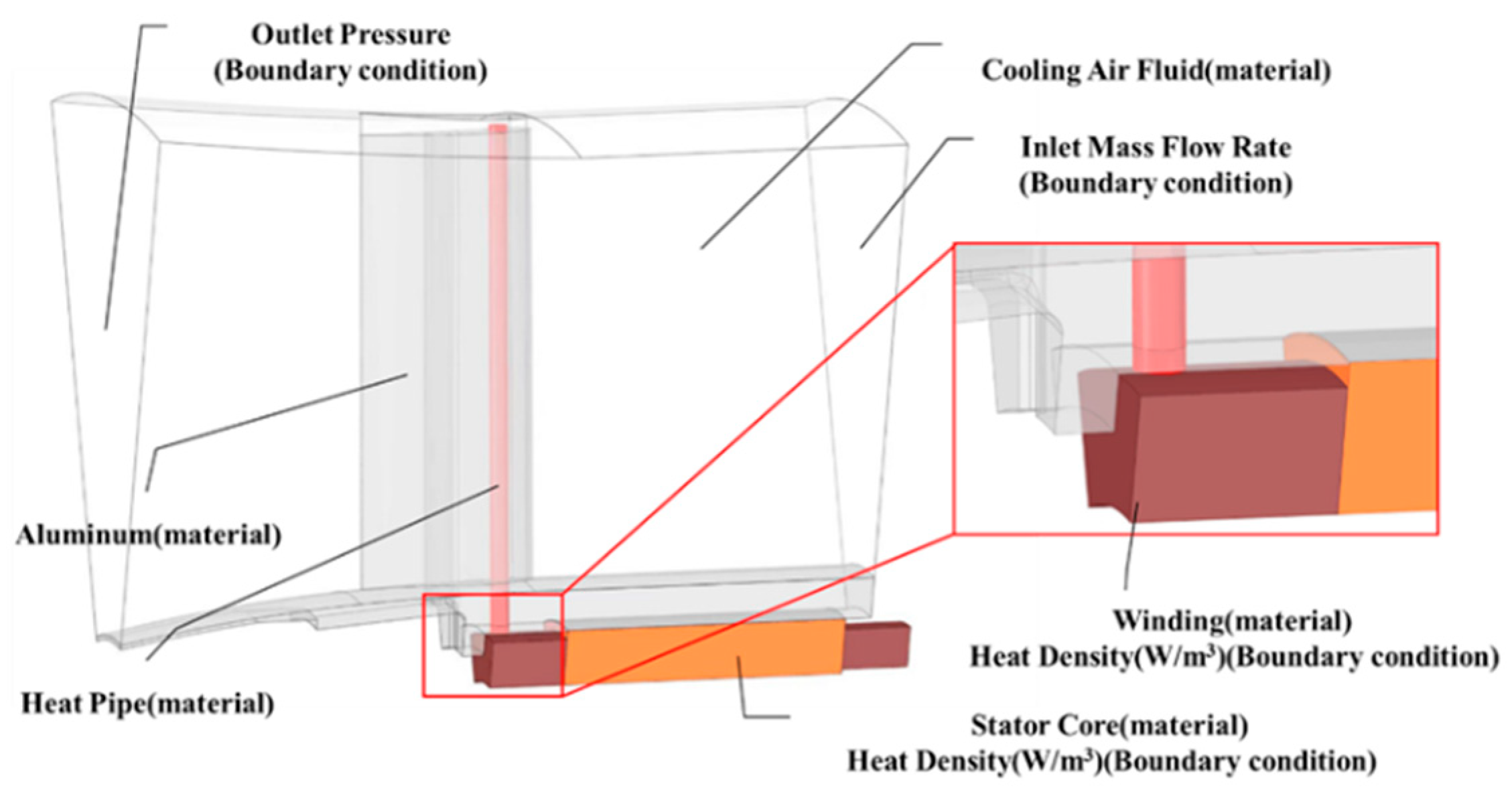
In this section, we describe a CFD model that was employed to evaluate the thermal benefits of the CGVHP for the electrical machine in the EDF. The commercial software ANSYS-Fluent was used here. The CFD model and main boundary conditions are depicted in Figure 10. In the method used here, both the solid and fluid domains are modeled to calculate the convection heat transfer between the solid and fluids parts. Due to the symmetry in the circumferential direction, only one-twelfth of the stator is modeled, which reduces the computation costs.

Figure 10.
CFD Model Setup.
For the materials used in the CFD model, the thermal conductivities of the heat pipe, cooling guide vane, and stator housing are isotropic. For the stator core, due to the insulation film between the stator laminations, the thermal conductivity in the axial direction is much lower than that in the radial direction. As for the stator winding, it is composed of a randomly placed round copper conductor with an insulation film and impregnation material. Therefore, an equivalent model of the stator winding is needed to reduce the model’s complexity. In the CFD model, the winding is modeled as a solid winding with anisotropic thermal conductivity. The simplified winding model enables the calculation accuracy to be maintained. The determination of the equivalent thermal conductivity of the stator winding is based on the model proposed in [31]. The physical properties of the materials are shown in Table 4.
Table 4.
Material Properties of the Model.
For the solver setting, the Reynolds-averaged Navier–Stokes (RANS) equations are used to model the complex turbulence in a time-averaged form:
where U and represent the fluid time-averaged and fluctuating velocity components, respectively; ρ is the fluid density and µ is the fluid dynamic viscosity; Sij is the mean strain-rate tensor; and is the symmetric Reynolds stress tensor, with six components. The standard k-epsilon turbulence model is used in this paper.
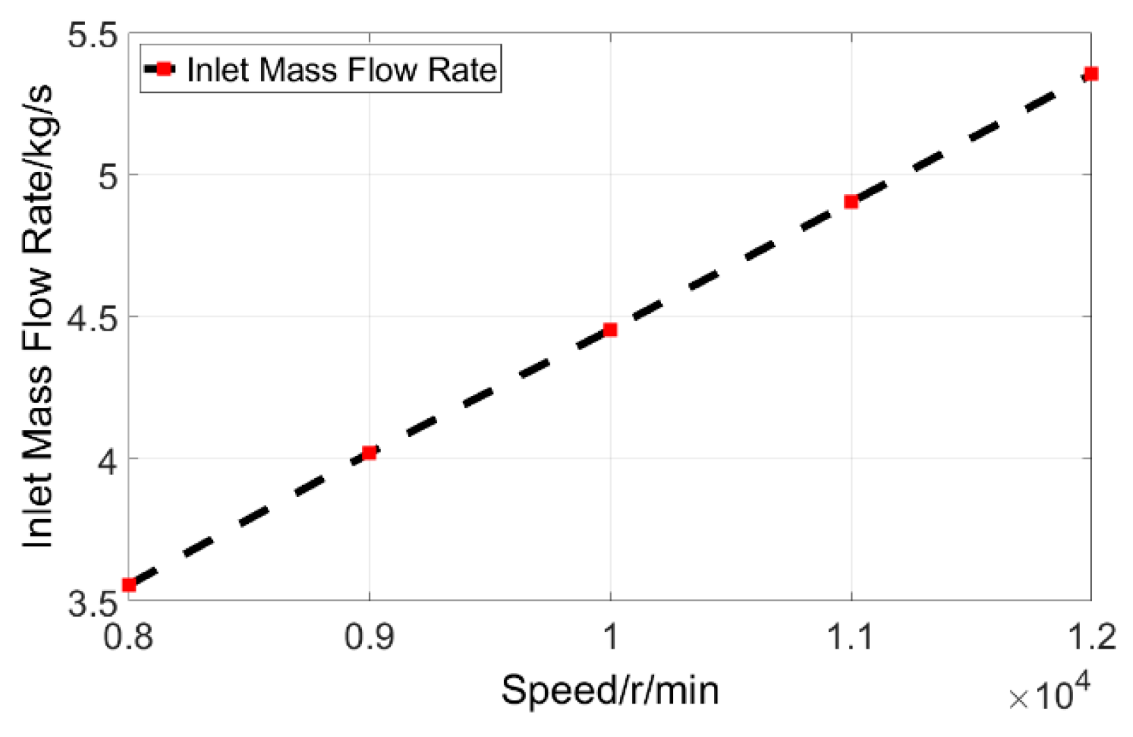
The inlet cooling air flow is set as 25 °C, with the inlet mass flow rate calculated by the aerodynamic design of the ducted fan, which is shown in Figure 11.

Figure 11.
The Inlet Mass Flow Rate with the Fan Speed.
4.2. Electrical Machine Losses
In the CFD model, only the stator part of the electrical machine is modeled for the purpose of reducing the computational costs. The machine loss calculation is carried out in this section and is imported into the CFD model as heat sources in order to calculate the temperature distribution. The power loss in the electrical machine stator is directly associated with the fan torque and speed curve, as shown in Figure 4. The power loss in the stator includes the copper loss in the stator winding and the core loss in the stator lamination.
Copper loss is the most direct cause of the temperature rise in the stator winding. Copper loss can be divided into DC loss, caused by the conductor’s electrical resistivity, and AC loss, caused by the effects of the conductor on the skin depth under a high electrical frequency. The copper loss can be expressed by:
where Pdc can be estimated by Pdc = J2curmsVcuρcu and AC loss Pac can be estimated by:
For the electrical machine with a fractional slot concentrated winding, the harmonic order of the air gap flux density is much higher; therefore, the core loss increases greatly when the electrical machine operates in a high-speed region. The core loss can be calculated by the classical Bertotti model, which is expressed as .
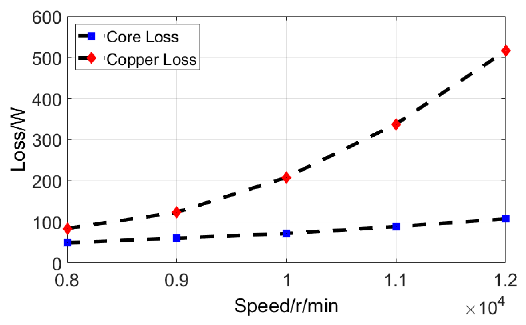
As a result, the calculated core loss and copper loss of the whole stator, with the fan speed, are shown in Figure 12. With the speed increasing from 8000 to 12,000 r/min, the core loss of the stator increases from 49.4 W to 107.4 W. Meanwhile, the rotor torque of the EDF grows proportionally with the increasing speed, and the resulting copper loss increases rapidly from 83.93 W to 516 W, with a growth of nearly 6.15 times. The sharply increased copper loss entails significant requirements for the thermal management of the stator winding.
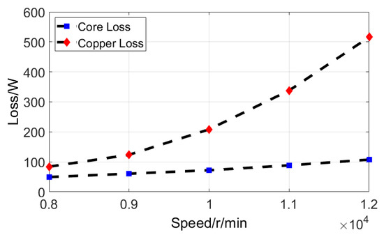
Figure 12.
The Power Loss of The Electric Machine.
4.3. Cooling Guide Vane
The heat dissipated through the cooling guide vane by the forced convection heat transfer can be expressed as:
where qout is the heat rejected by the cooling guide vane, TCG represents the cooling guide vane temperature, and Tamb is the ambient temperature. The hout represents the convective heat transfer coefficient that depends on the Nusselt number and cooling guide vane geometry. A is the convection aera of the cooling guide vane. Therefore, the hout can be expressed as:
where kair stands for the air’s thermal conductivity, and S represents the distance between the two adjacent cooling guide vanes. For the forced convection, the Nusselt number can be represented by:
where Re represents the Reynolds number, which is dependent on the air velocity, the distance between the two adjacent cooling guide vanes, and air kinematic viscosity.
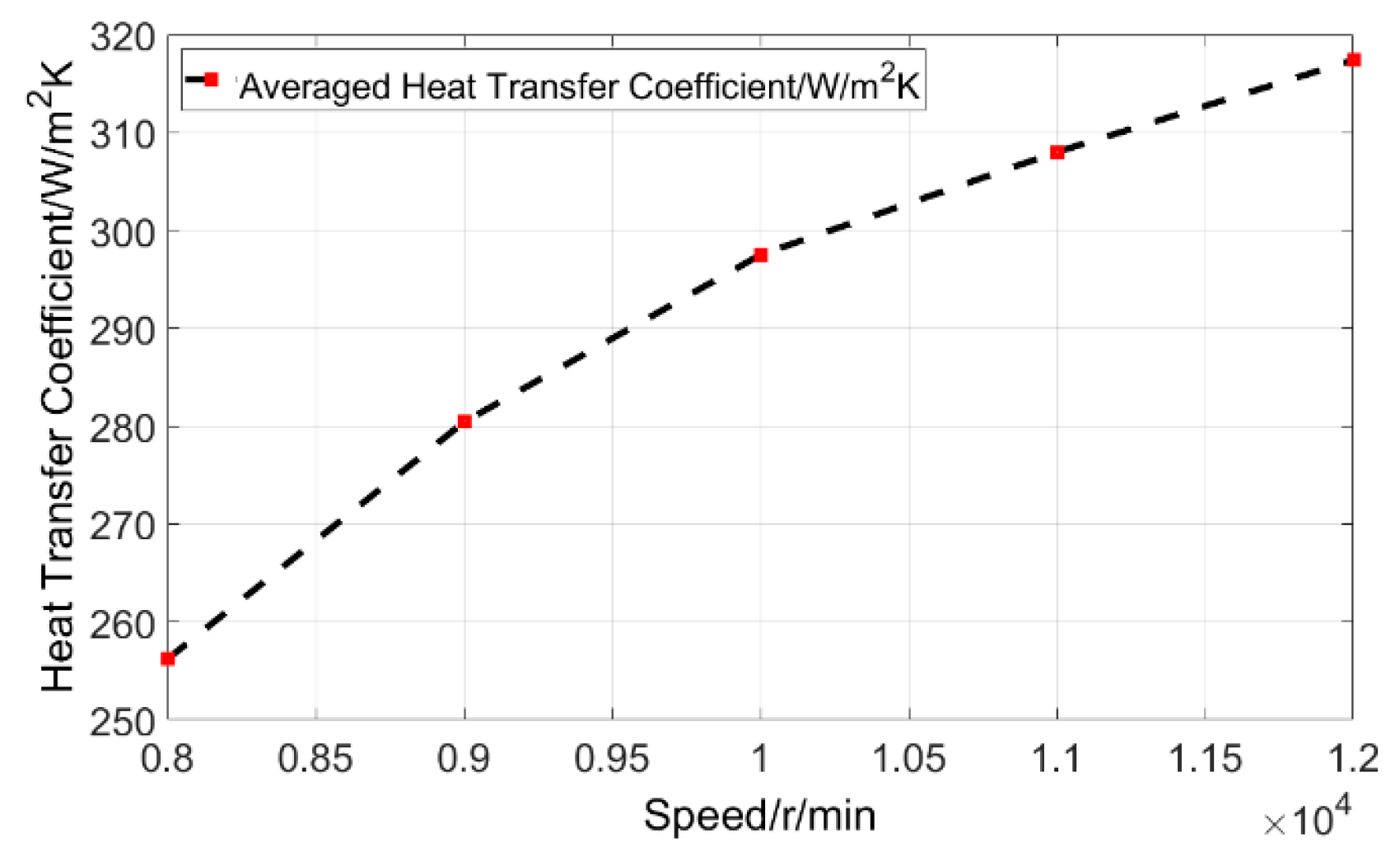
Figure 13 shows the relevant heat transfer coefficient distribution at speeds of 8000 r/min and 12,000 r/min. It shows that the heat transfer coefficient of the convection process is greatly improved by the increased air velocity. The area with a higher heat transfer coefficient is expanded along the leading edge and trailing edge of the cooling guide vane, as shown in Figure 12. The averaged heat transfer coefficient of the cooling guide vane is increased from 256.2 W/m2K to 317.4 W/m2K with the speed increasing from 8000 to 12,000 r/min, as shown in Figure 14.
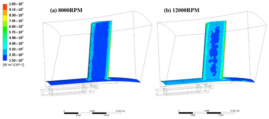
Figure 13.
The Power Loss of The Electrical Machine.
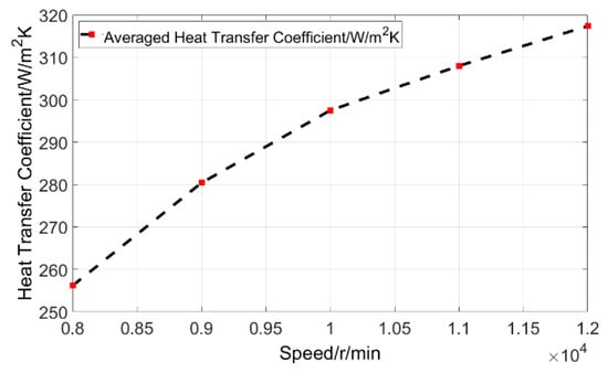
Figure 14.
Averaged Heat Transfer Coefficient of the Cooling Guide Vane.
5. Results and Discussion
In this section, the thermal performance of the cooling guide vane, along with the heat pipe, is evaluated based on the calculation results. As mentioned in earlier sections, the adoption of the heat pipe provides an additional heat dissipation path for the stator winding, whose heat dissipation capacity can be strongly influenced by the thermal conductivity of the heat pipe. Therefore, firstly, the temperature variation in the stator winding, along with the thermal conductivity of the heat pipe, at various speeds is illustrated. Secondly, the heat fluxes of the corresponding heat exchange surfaces are derived and compared, which account for the temperature reduction in the stator winding and stator core of the electrical machine.
To account for the heat flux and heat exchange rate in different heat conductive path due to the different thermal conductivity of the heat pipe, two heat transfer interfaces are incorporated into the model, as shown in Figure 15. The first interface is the contact area between the heat pipe and the end winding coil, while the second interface is between the stator core and the stator housing. The heat generated in the stator core and winding is dissipated through these two heat transfer interfaces. The corresponding surface area of heat transfer interface 1 and heat transfer interface 2, used for exchanging heat, are 148.33 mm2 and 1321.8 mm2, respectively. These areas are used to calculate the heat transfer capacities of the two heat interfaces in the subsequent analysis.
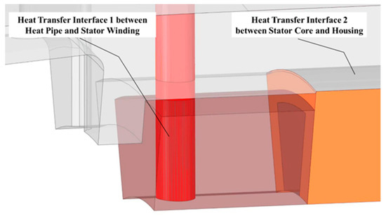
Figure 15.
Heat Transfer Interfaces.
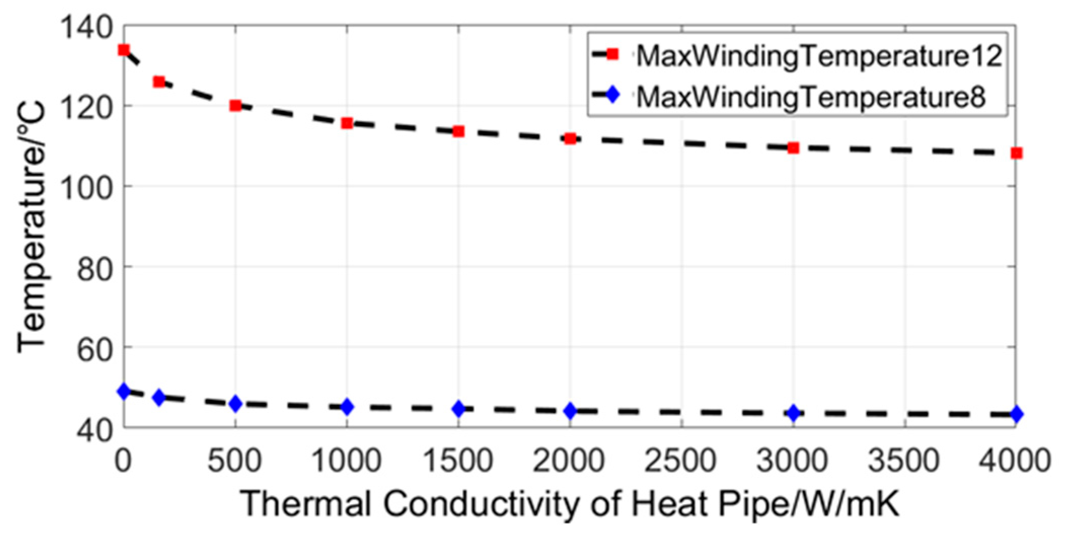
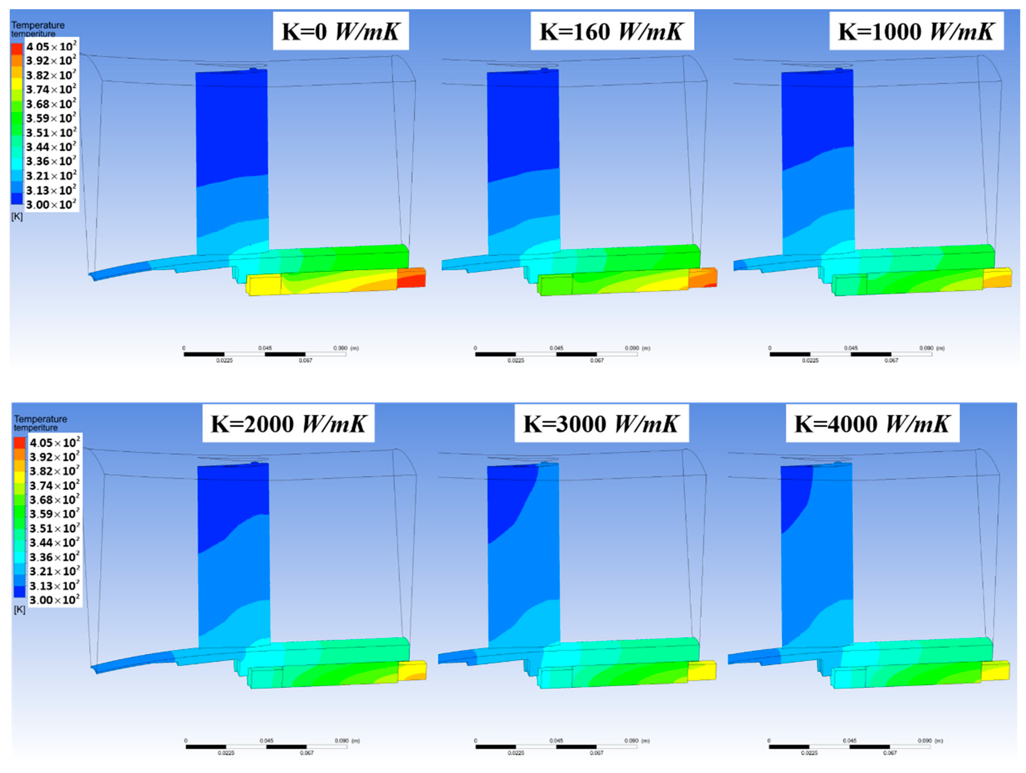
The maximum temperature in the stator winding under different degrees of thermal conductivity of the heat pipe is shown in Figure 16. MaxWindingTemperature12 represents the maximum winding temperature under the thermal load of the corresponding fan rotation speed of 12,000 r/min, while MaxWindingTemperature8 represents that of 8000 r/min. It shows that the maximum temperature of the winding significantly decreases with the increase in the heat pipe’s thermal conductivity. The maximum temperature of the winding under the fan rotation speed of 12,000 r/min is reduced from 133.7 ℃ to 108.2 °C with the thermal conductivity of the heat pipe increasing from 0 to 4000 W/mK, and a reduction of nearly 25.5 °C is achieved. This reduction in the maximum winding temperature is caused by the lower thermal resistance which is created by the heat pipe between the end winding and the cooling guide vane. However, the maximum temperature of the winding under a fan rotation speed of 8000 r/min is much lower than that of 12,000 r/min, mainly due to the much lower copper loss, as shown in Figure 12. The respective temperature distribution in the stator part with the cooling guide vane of the heat pipe at the fan rotation speed of 12,000 r/min under different thermal conductivities is shown in Figure 17. It is also worth noting that with the increased thermal conductivity of the heat pipe, the higher temperature zone is expanded from the hub to the tip of the cooling guide vane, resulting in an increased temperature difference between the cooling guide vane and the cooling air flow. The increased temperature difference is also beneficial for enhancing the convection capability.

Figure 16.
Maximum Winding Temperature under Different Thermal Conductivities of the Heat Pipe.

Figure 17.
Temperature Distribution of the Stator Part with the Cooling Guide Vane at 12,000 r/min.
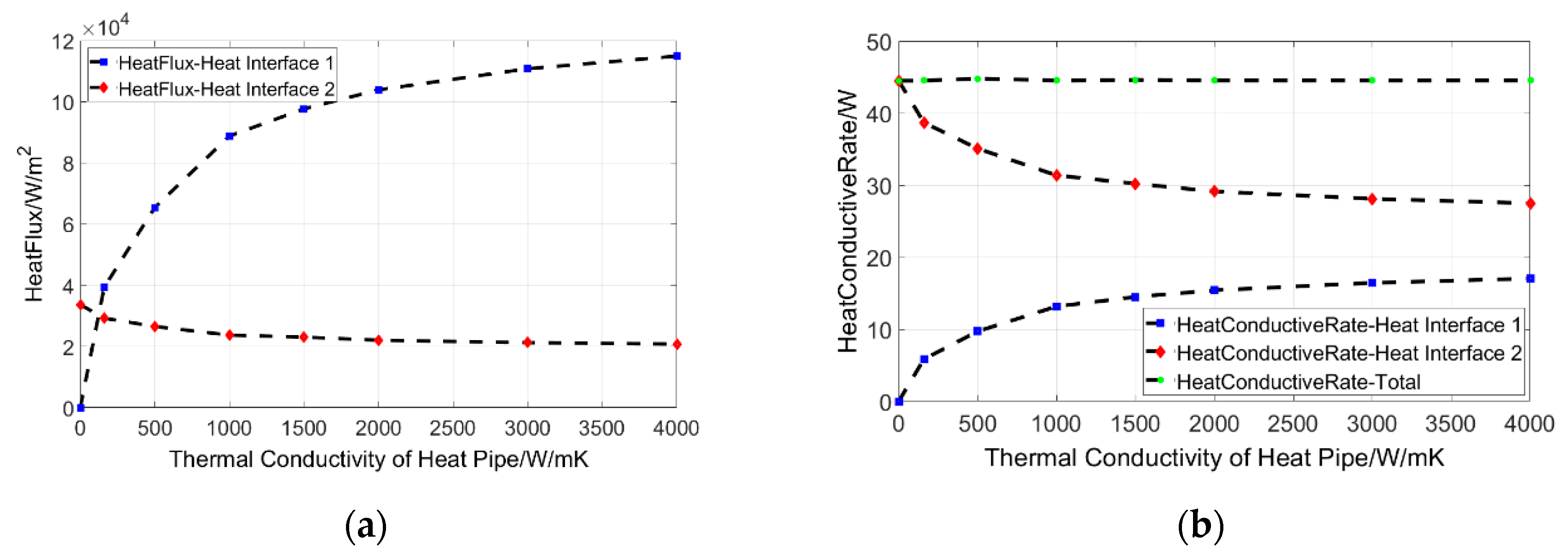
The lower thermal resistance between the end winding and the cooling guide vane also influences the heat flux distribution in the different heat conductive paths. This is indicated in Figure 18a. The heat flux in heat transfer interface 1 increases from 0 W/m2 to a maximum of 115,000 W/m2 when the thermal conductivity of the heat pipe increases from 0 to 4000 W/mK. Meanwhile, the heat flux in heat transfer interface 2 decreases from 33,660 W/m2 to 20,794 W/m2. The corresponding heat transfer capacities through the heat transfer interfaces are shown in Figure 18b. Clearly, it can be seen that more than 17 W of heat is transmit to the cooling guide vane by the heat pipe when the thermal conductivity of the heat pipe is increased to 4000 W/mK. Meanwhile, the heat dissipated through the stator and housing is reduced from 44 W to 27 W. The total heat transfer capacity through the two heat transfer interfaces remains unchanged.
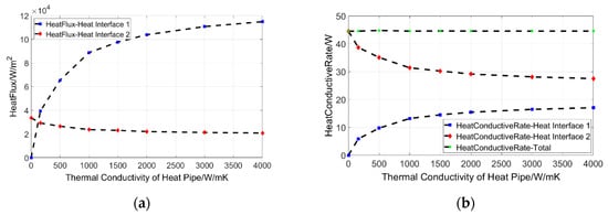
Figure 18.
Heat Flux and Heat Transfer Capacity through Two Heat Transfer Interfaces: (a) Heat Flux; (b) Heat Transfer Capacity.
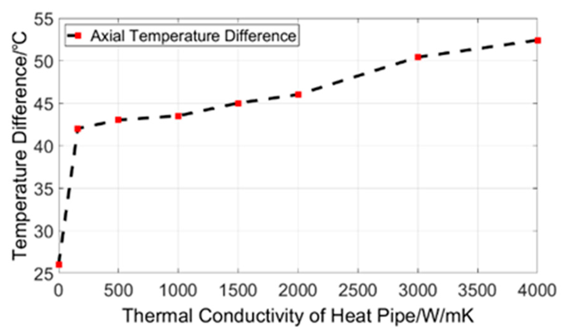
As more heat is dissipated in the stator winding through the heat pipe, the temperature in the end winding reduces significantly. In the proposed CGVHP, a single heat pipe is installed on one side of the end winding. The large temperature reduction in the end winding, which is due to the high thermal conductivity of the heat pipe, leads to an increase in the winding temperature difference in the axial direction. The temperature difference in the axial direction increases from 26 to 52.4 °C when the thermal conductivity of the heat pipe increases from 0 to 4000 W/mK, as shown in Figure 19. The axial winding temperature difference implies that the heat transfer of the winding in axial the direction is worthy of extensive study. The winding temperature could be further reduced if the equivalent axial thermal conductivity of the winding were to be improved.
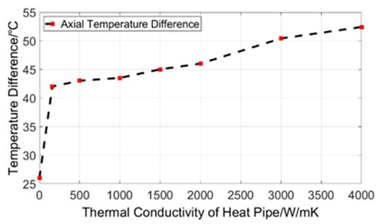
Figure 19.
Winding Temperature Difference in the Axial Direction.
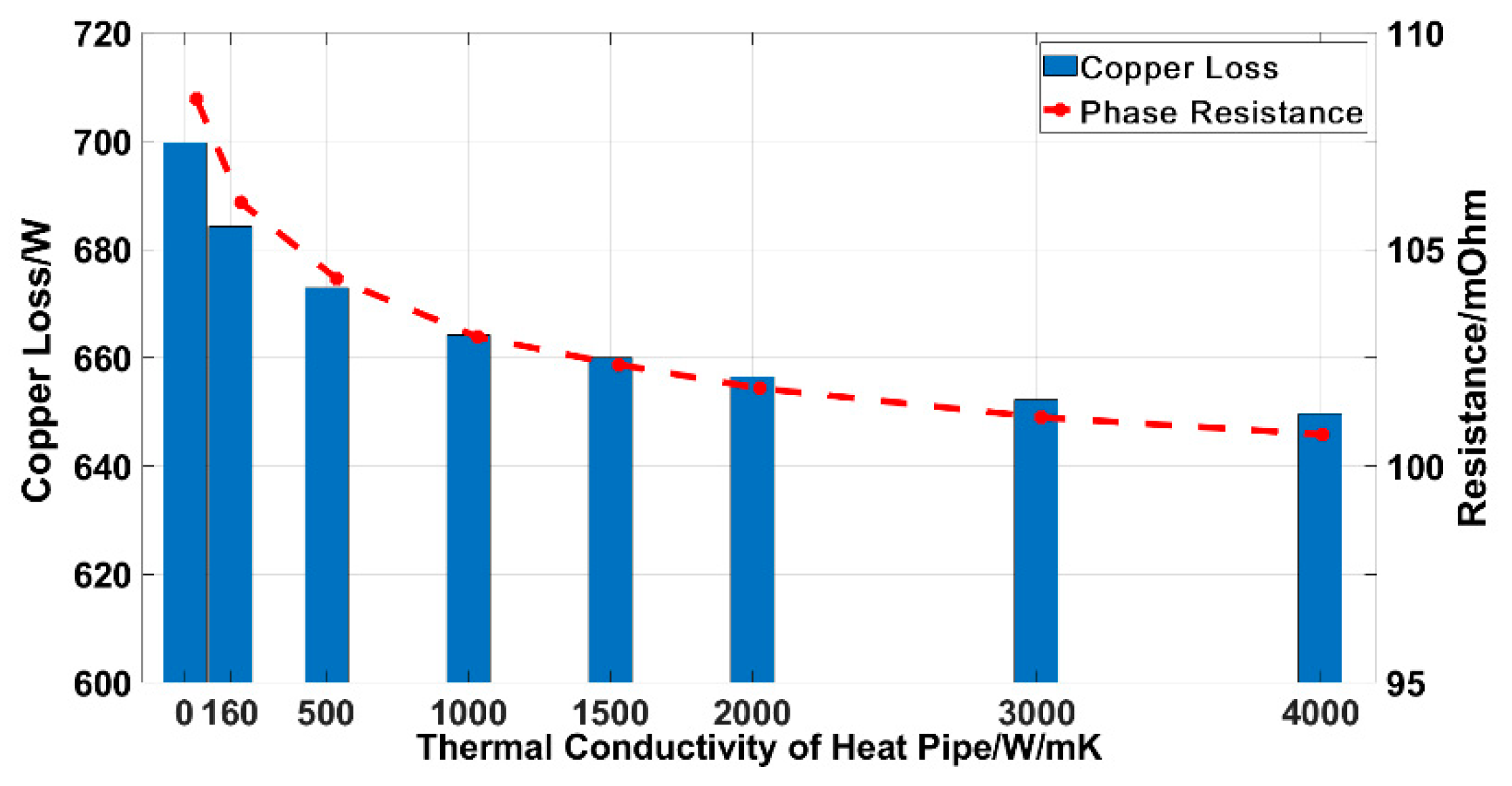
In terms of the electromagnetic benefits of the proposed CGVHP, one of the major benefits of the temperature reduction is the winding resistance, which is reduced simultaneously. As is known, the electrical resistance of a copper wire increases with the temperature increase. A lower winding temperature enables a lower electrical resistance. The phase change and copper loss change due to the winding temperature reduction, along with the thermal conductivity of the heat pipe, are shown in Figure 20. In the electrical machine under investigation, the phase resistance of the winding is decreased from 108.48 mOhm to 100.73 mOhm, with the winding temperature decreased by 25 °C, which means that a 7.14% reduction in the phase resistance is achieved. Consequently, this reduction in the phase resistance enables a 50 W corresponding reduction in the copper loss, which decreases from 699.72 W to 649.726 W, which further benefits the temperature reduction in the stator winding and improvement in the electrical machine’s efficiency.

Figure 20.
Phase Resistance and Copper Loss Change due to the Winding Temperature.
6. Conclusions
This paper presented a type of CGVHP technology that can be used for the thermal management of an electrical machine in an EDF. An EDF with a 15.7 kW, 12,000 r/min electrical machine was investigated in order to validate the thermal performance of the proposed CGVHP.
The numerical simulation results showed that the maximum winding temperature can be reduced by over 25.5 °C by using the cooling guide vane and the heat pipe, compared with only cooling guide vane, in peak conditions. For the entire electrical machine, the CGVHP is used to realize a copper loss saving of approximately 50 W, accounting for a 7.14% reduction in the phase resistance and total copper loss.
The CGVHP technology proposed in this study achieved a significant temperature reduction in the stator winding for an electrical machine of the EDF. This technology could be further applied to integrated turbo-electric generators, boundary layer ingestion fans, cooling fans, etc., for which thermal management is a critical aspect of the devices’ safe operation and the power density is a key requirement for a light weight. Future work will focus on the aerodynamic design and experimental validation of the proposed CGVHP technology for electrical machines.
Author Contributions
Conceptualization, X.H. and Y.Z.; methodology, X.H.; validation, X.H., C.D. and Y.Q.; formal analysis, Y.Q.; resources, Y.Z. and C.W.; writing—original draft preparation, X.H.; writing—review and editing, Y.Q.; visualization, C.D.; supervision, Y.Z.; project administration, W.Z.; funding acquisition, Y.Z. and W.Z. All authors have read and agreed to the published version of the manuscript.
Funding
This research was funded in part by the Advanced Aviation Power Innovation Institution and the Aero Engine Academy of China. It is also funded in part by the Tsinghua University Initiative Scientific Research Program.
Institutional Review Board Statement
Not applicable.
Informed Consent Statement
Not applicable.
Data Availability Statement
Not applicable.
Conflicts of Interest
The authors declare no conflict of interest.
References
- Garrow, L.A.; German, B.J.; Leonard, C.E. Urban air mobility: A comprehensive review and comparative analysis with autonomous and electric ground transportation for informing future research. Transp. Res. Part C Emerg. Technol. 2021, 132, 103377. [Google Scholar] [CrossRef]
- Rajendran, S.; Srinivas, S. Air taxi service for urban mobility: A critical review of recent developments, future challenges, and opportunities. Transp. Res. Part E Logist. Transp. Rev. 2020, 143, 102090. [Google Scholar] [CrossRef]
- Morgan, S. Flying Cars: Investment Implications of Autonomous Urban Airmobility; Morgan Stanley: New York, NY, USA, 2018. [Google Scholar]
- Baur, S.; Schickram, S.; Homulenko, A.; Martinez, N.; Dyskin, A. Urban air mobility: The rise of a new mode of transportation. Available online: https://www.rolandberger.com/publications/publication_pdf/Roland_Berger_Urban_Air_Mobility.pdf (accessed on 3 October 2022).
- Brown, K.A.; Fleming, J.L.; Langford, M.; Ng, W.; Schwartz, K.; Combs, C. Development of a Ducted Propulsor for BLI Electric Regional Aircraft—Part I: Aerodynamic Design and Analysis. In Proceedings of the AIAA Propulsion and Energy 2019 Forum, Indianapolis, IN, USA, 19–22 August 2019. [Google Scholar]
- Zhang, T.; Barakos, G. Review on ducted fans for compound rotorcraft. Aeronaut. J. 2020, 124, 941–974. [Google Scholar] [CrossRef]
- Zong, J.; Zhu, B.; Hou, Z.; Yang, X.; Zhai, J. Evaluation and Comparison of Hybrid Wing VTOL UAV with Four Different Electric Propulsion Systems. Aerospace 2021, 8, 256. [Google Scholar] [CrossRef]
- Technology Blog. 2022. Available online: https://lilium.com/newsroom-detail/technology-behind-the-lilium-jet (accessed on 4 October 2022).
- RWTH-Acchen, I. Silent Propulsors for Air Taxis. Available online: https://www.ist.rwth-aachen.de/cms/IST/Forschung/Research-areas/~nzmau/Silent-propulsors-for-air-taxis/lidx/1/ (accessed on 4 October 2022).
- About e.SAT. 2022. Available online: https://e-sat.de/en/about-e.sat/ (accessed on 4 October 2022).
- Sayed, E.; Abdalmagid, M.; Pietrini, G.; Sa’adeh, N.M.; Callegaro, A.D.; Goldstein, C.; Emadi, A. Review of Electric Machines in More-/Hybrid-/Turbo-Electric Aircraft. IEEE Trans. Trans. Electr. 2021, 7, 2976–3005. [Google Scholar] [CrossRef]
- El-Refaie, A.; Osama, M. High specific power electrical machines: A system perspective. CES Trans. Electr. Mach. Syst. 2019, 3, 88–93. [Google Scholar] [CrossRef]
- Hebala, A.; Nuzzo, S.; Connor, P.H.; Giangrande, P.; Gerada, C.; Galea, M. Improved Propulsion Motor Design for a Twelve Passenger All-Electric Aircraft. In Proceedings of the 2021 IEEE Workshop on Electrical Machines Design, Control and Diagnosis (WEMDCD), Modena, Italy, 8–9 April 2021; pp. 343–348. [Google Scholar] [CrossRef]
- Vannini, A.; Marfoli, A.; Papini, L.; Bolognesi, P.; Gerada, C. Materials for Electric Machines Suited for High-Temperature Applications: A Survey. In Proceedings of the 2021 IEEE Workshop on Electrical Machines Design, Control and Diagnosis (WEMDCD), Modena, Italy, 8–9 April 2021; pp. 101–106. [Google Scholar] [CrossRef]
- Dong, C.; Qian, Y.; Zhang, Y.; Zhuge, W. A Review of Thermal Designs for Improving Power Density in Electrical Machines. IEEE Trans. Transp. Electrif. 2020, 6, 1386–1400. [Google Scholar] [CrossRef]
- Meng, T.; Zhang, P. A Review of Thermal Monitoring Techniques for Radial Permanent Magnet Machines. Machines 2021, 10, 18. [Google Scholar] [CrossRef]
- Jin, Y.; Qian, Y.; Zhang, Y.; Zhuge, W. Modeling of Ducted-Fan and Motor in an Electric Aircraft and a Preliminary Integrated Design. SAE Int. J. Aerosp. 2018, 11, 115–126. [Google Scholar] [CrossRef]
- Yi, X.; Sanchez, R.; Haran, K.; Veres, J.; Perry, A.T.; Ansell, P.J. Self-Pumped Air-Cooling Design for a High-Speed High-Specific-Power Motor. In Proceedings of the 2018 IEEE Transportation Electrification Conference and Expo (ITEC), Long Beach, CA, USA, 13–15 June 2018. [Google Scholar]
- Yoon, A.K.; Xiao, J.; Lohan, D.; Arastu, F.; Haran, K.S. High-Frequency Electric Machines for Boundary Layer Ingestion Fan Propulsor. IEEE Trans. Energy Convers. 2019, 34, 2189–2197. [Google Scholar] [CrossRef]
- Yu, Z.; Li, Y.; Jing, Y.; Wang, J. Cooling System of Outer Rotor SPMSM for a Two-Seater All-Electric Aircraft Based on Heat Pipe Technology. IEEE Trans. Transp. Electrif. 2021, 8, 1656–1664. [Google Scholar] [CrossRef]
- Le, W.; Lin, M.; Lin, K.; Liu, K.; Jia, L.; Yang, A.; Wang, S. A Novel Stator Cooling Structure for Yokeless and Segmented Armature Axial Flux Machine with Heat Pipe. Energies 2021, 14, 5717. [Google Scholar] [CrossRef]
- Geng, W.; Zhu, T.; Li, Q.; Zhang, Z. Windings Indirect Liquid Cooling Method for a Compact Outer-Rotor PM Starter/Generator With Concentrated Windings. IEEE Trans. Energy Convers. 2021, 36, 3282–3293. [Google Scholar] [CrossRef]
- Masson, P.J.; Pienkos, J.E.; Luongo, C.A. Scaling Up of HTS Motor Based on Trapped Flux and Flux Concentration for Large Aircraft Propulsion. IEEE Trans. Appl. Supercond. 2007, 17, 1579–1582. [Google Scholar] [CrossRef]
- Moon, S.-H.; Hwang, G.; Kim, S.-J.; Seo, J.-K. Thermal Analysis and Testing of a Heat Pipe With Woven Wired Wick. IEEE Trans. Compon. Packag. Manuf. Technol. 2014, 4, 991–998. [Google Scholar] [CrossRef]
- Hu, X.; Guo, H.; Qian, H.; Ding, X.; Yang, Y. Development of a high-power-density motor for formula SAE electric race car. In Proceedings of the IECON 2017-43rd Annual Conference of the IEEE Industrial Electronics Society, Beijing, China, 29 October–1 November 2017; pp. 6618–6622. [Google Scholar] [CrossRef]
- Putra, N.; Ariantara, B. Electric motor thermal management system using L-shaped flat heat pipes. Appl. Therm. Eng. 2017, 126, 1156–1163. [Google Scholar] [CrossRef]
- Dong, C.; Qian, Y.; Zhang, Y.; Hu, X.; Zhuge, W. Coupled Thermal-Electromagnetic Parametric Modeling of Permanent Magnet Machine Based on Flat Heat Pipe Cooling. In Proceedings of the 2020 23rd International Conference on Electrical Machines and Systems (ICEMS), Hamamatsu, Japan, 24–27 November 2020. [Google Scholar] [CrossRef]
- Huang, J.; Naini, S.S.; Miller, R.; Rizzo, D.; Sebeck, K.; Shurin, S.; Wagner, J. A Hybrid Electric Vehicle Motor Cooling System—Design, Model, and Control. IEEE Trans. Veh. Technol. 2019, 68, 4467–4478. [Google Scholar] [CrossRef]
- Liu, F.; Lan, F.; Chen, J. Dynamic thermal characteristics of heat pipe via segmented thermal resistance model for electric vehicle battery cooling. J. Power Sources 2016, 321, 57–70. [Google Scholar] [CrossRef]
- Greco, A.; Cao, D.; Jiang, X.; Yang, H. A theoretical and computational study of lithium-ion battery thermal management for electric vehicles using heat pipes. J. Power Sources 2014, 257, 344–355. [Google Scholar] [CrossRef]
- Simpson, N.; Wrobel, R.; Mellor, P.H. Estimation of Equivalent Thermal Parameters of Impregnated Electrical Windings. IEEE Trans. Ind. Appl. 2013, 49, 2505–2515. [Google Scholar] [CrossRef]


Publisher’s Note: MDPI stays neutral with regard to jurisdictional claims in published maps and institutional affiliations. |
© 2022 by the authors. Licensee MDPI, Basel, Switzerland. This article is an open access article distributed under the terms and conditions of the Creative Commons Attribution (CC BY) license (https://creativecommons.org/licenses/by/4.0/).