
Dual-Band Antenna at 28 and 38 GHz Using Internal Stubs and Slot Perturbations
 , ,
, ,  , and
, and 
Abstract
:1. Introduction
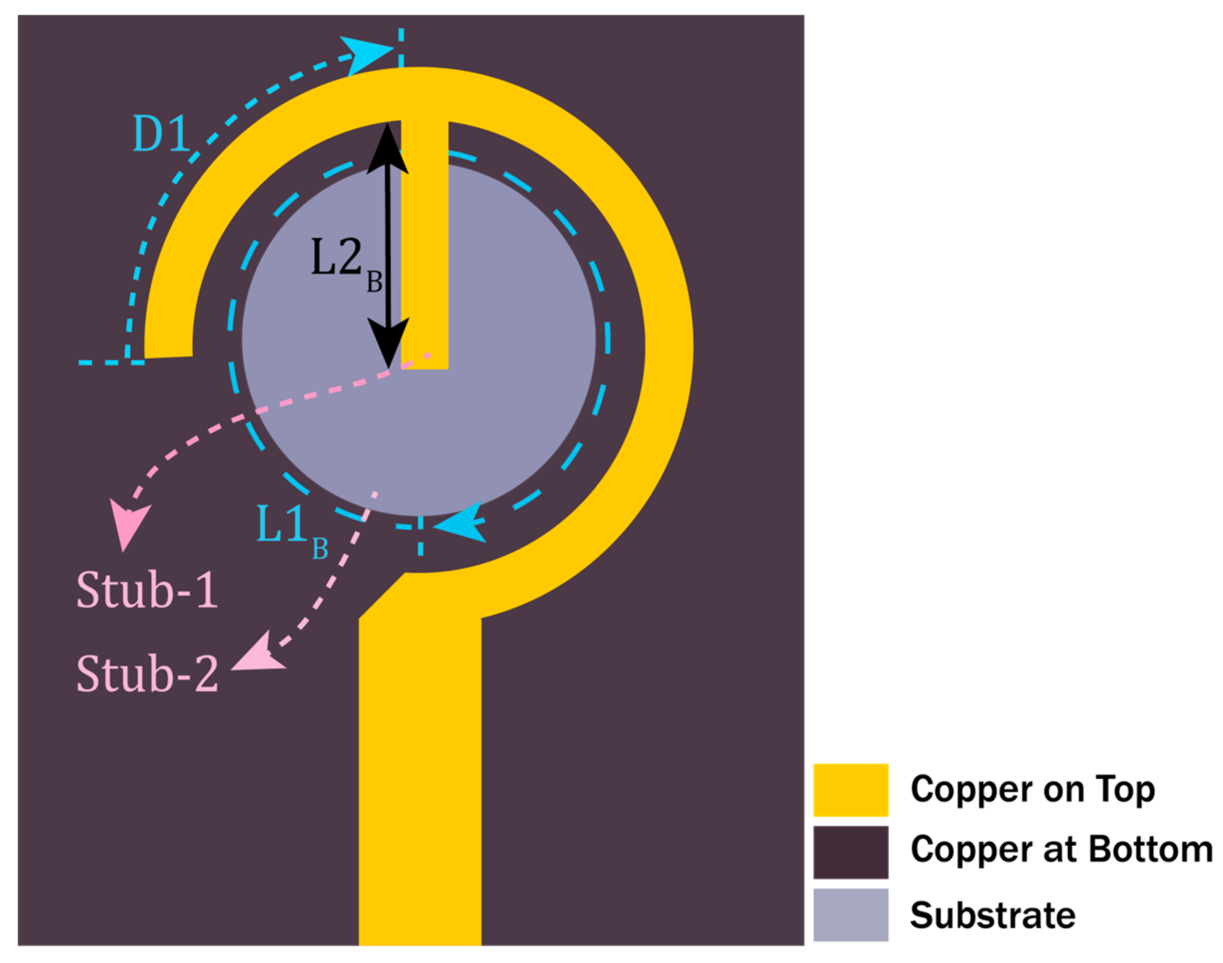
2. Design Methodology
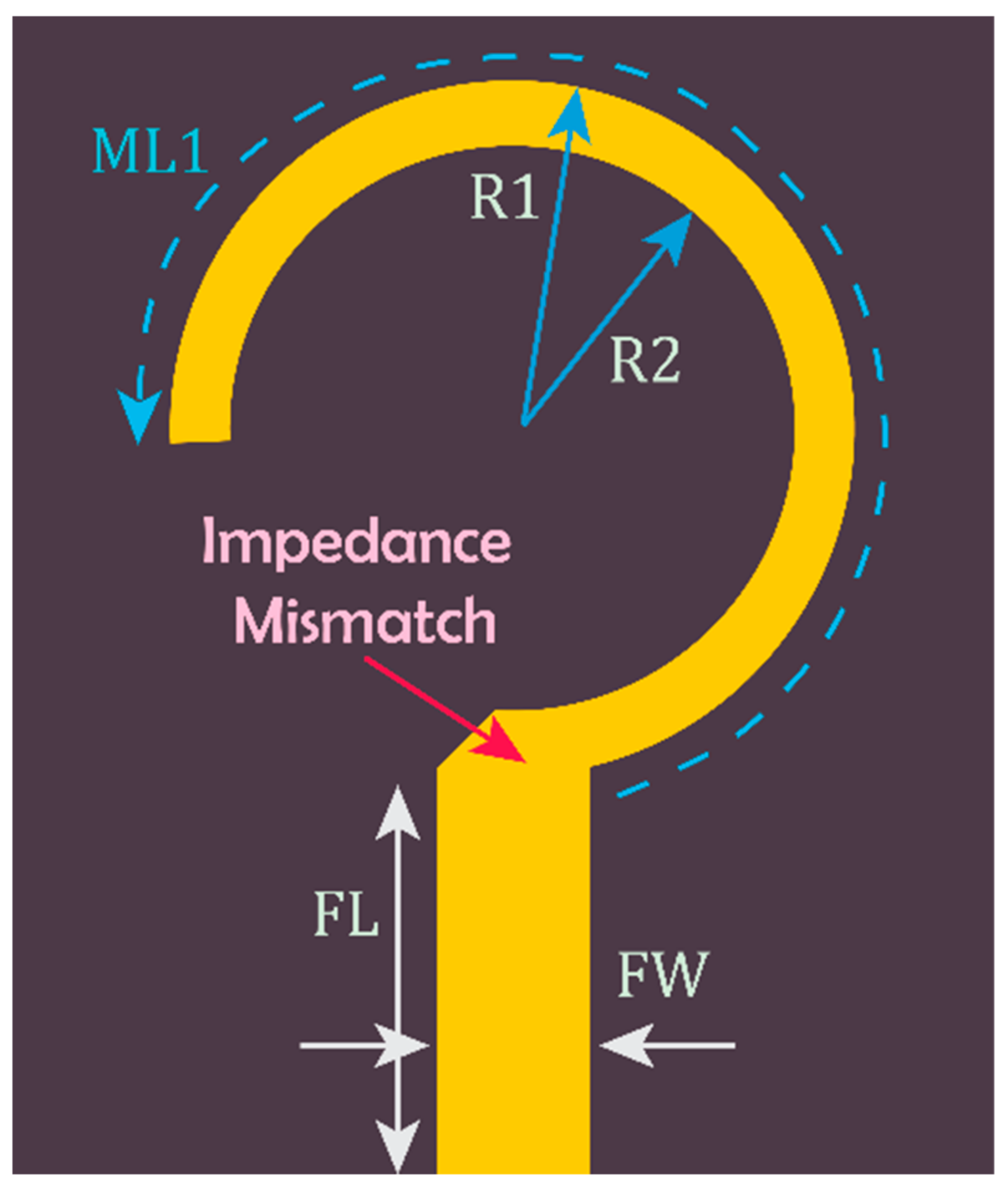
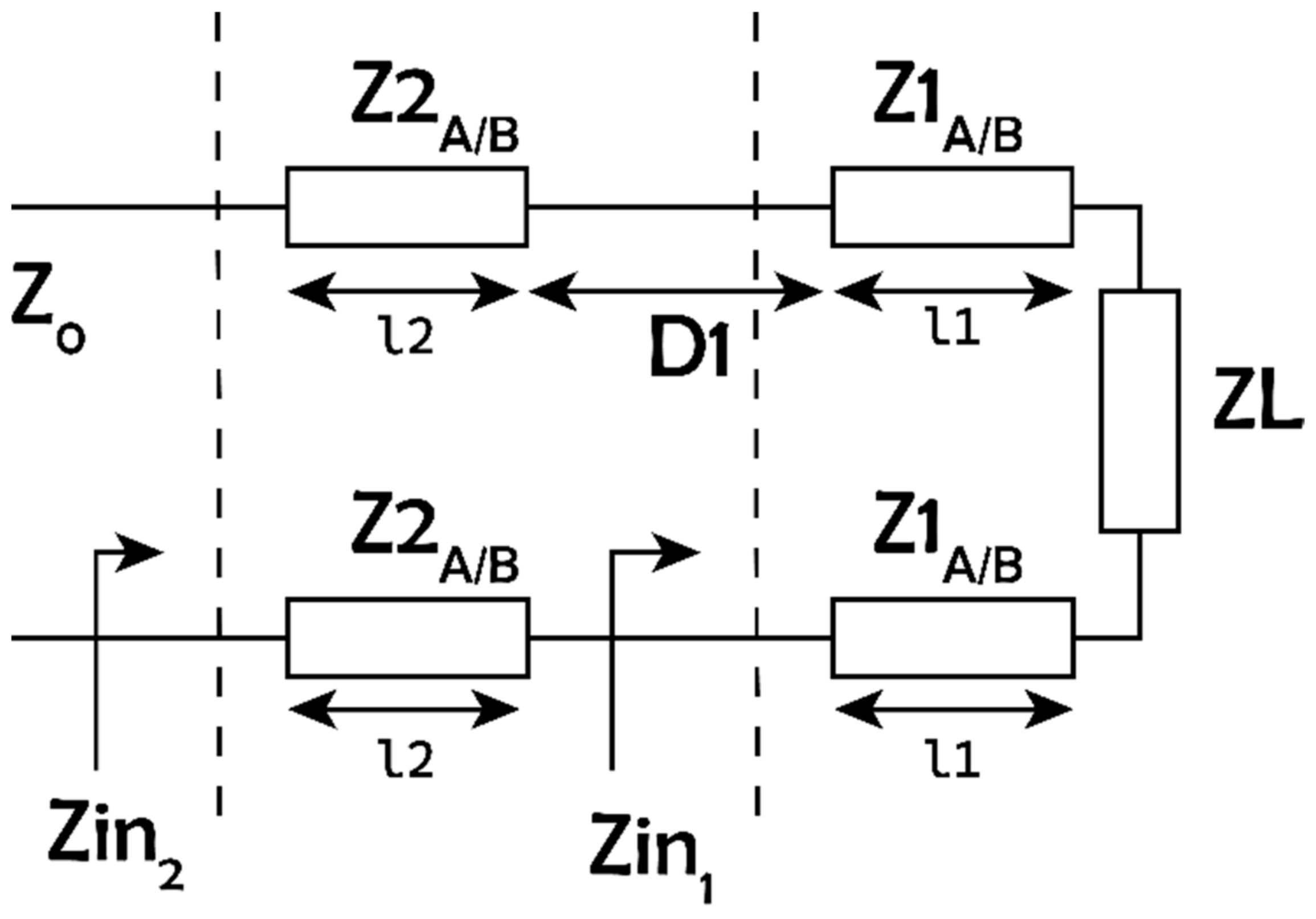
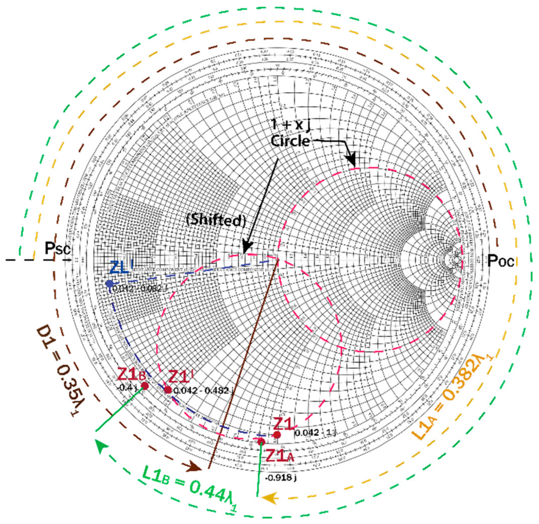
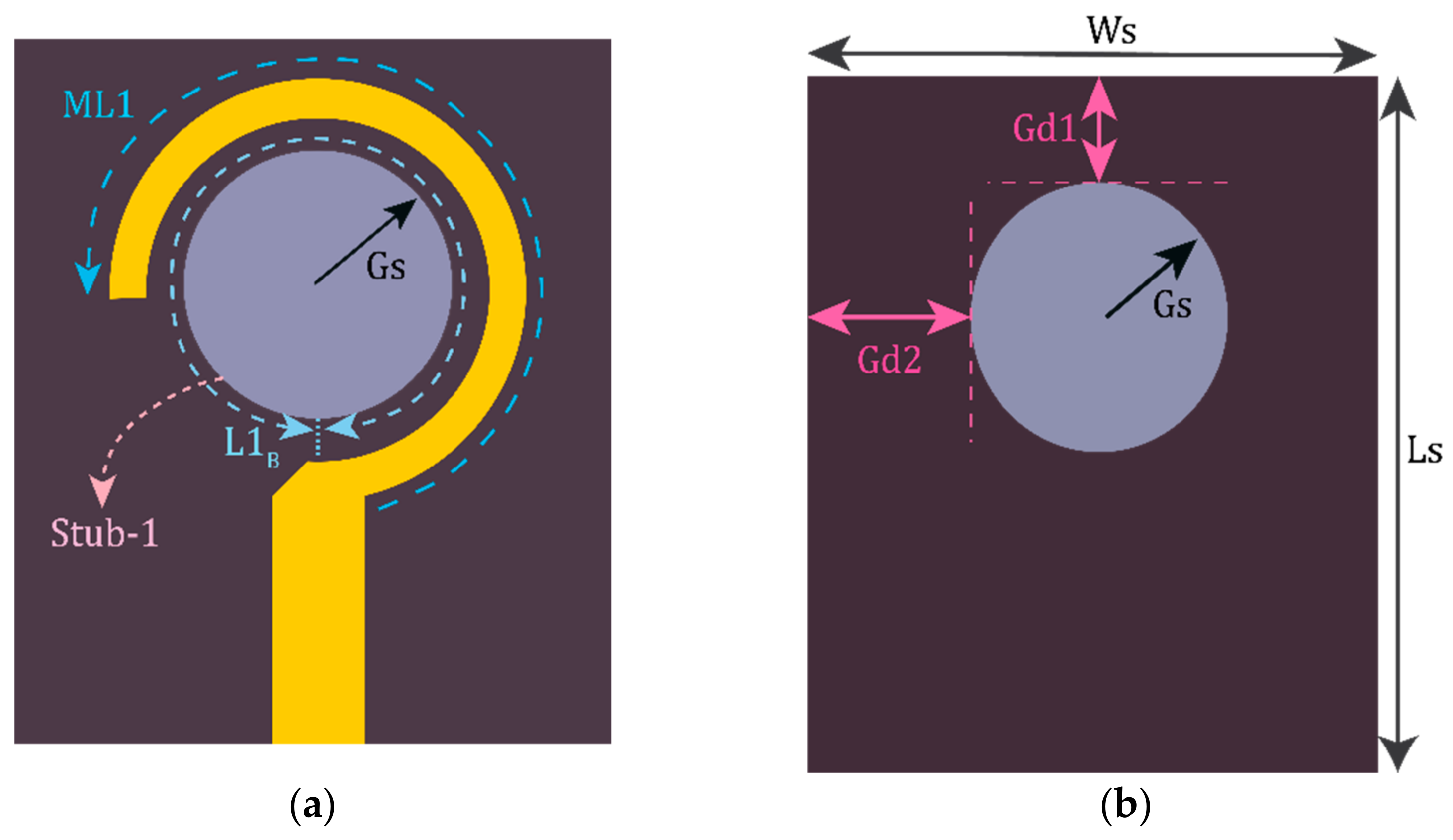
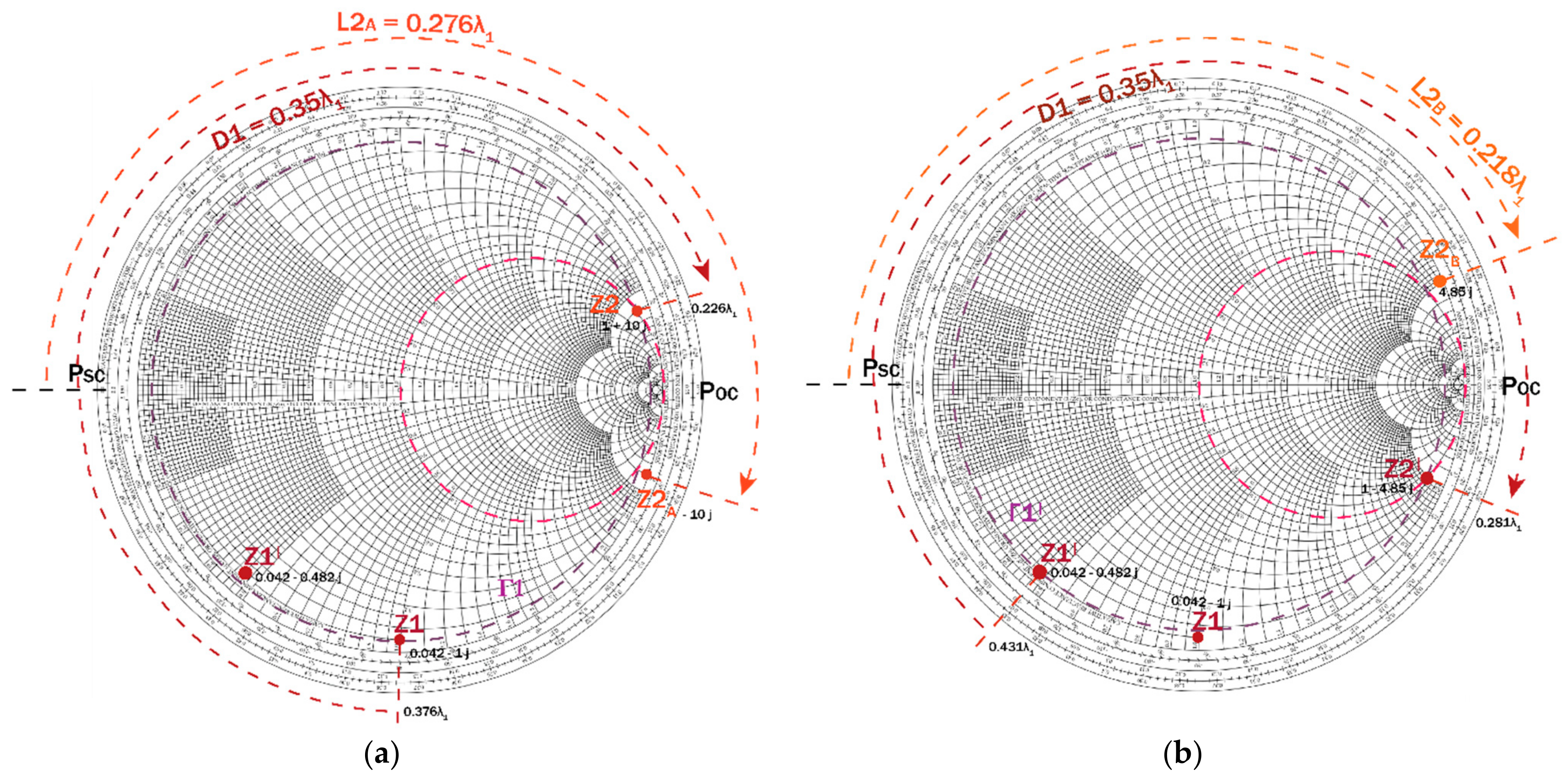
2.1. Matching Network (MN1) at 28 GHz (f1)
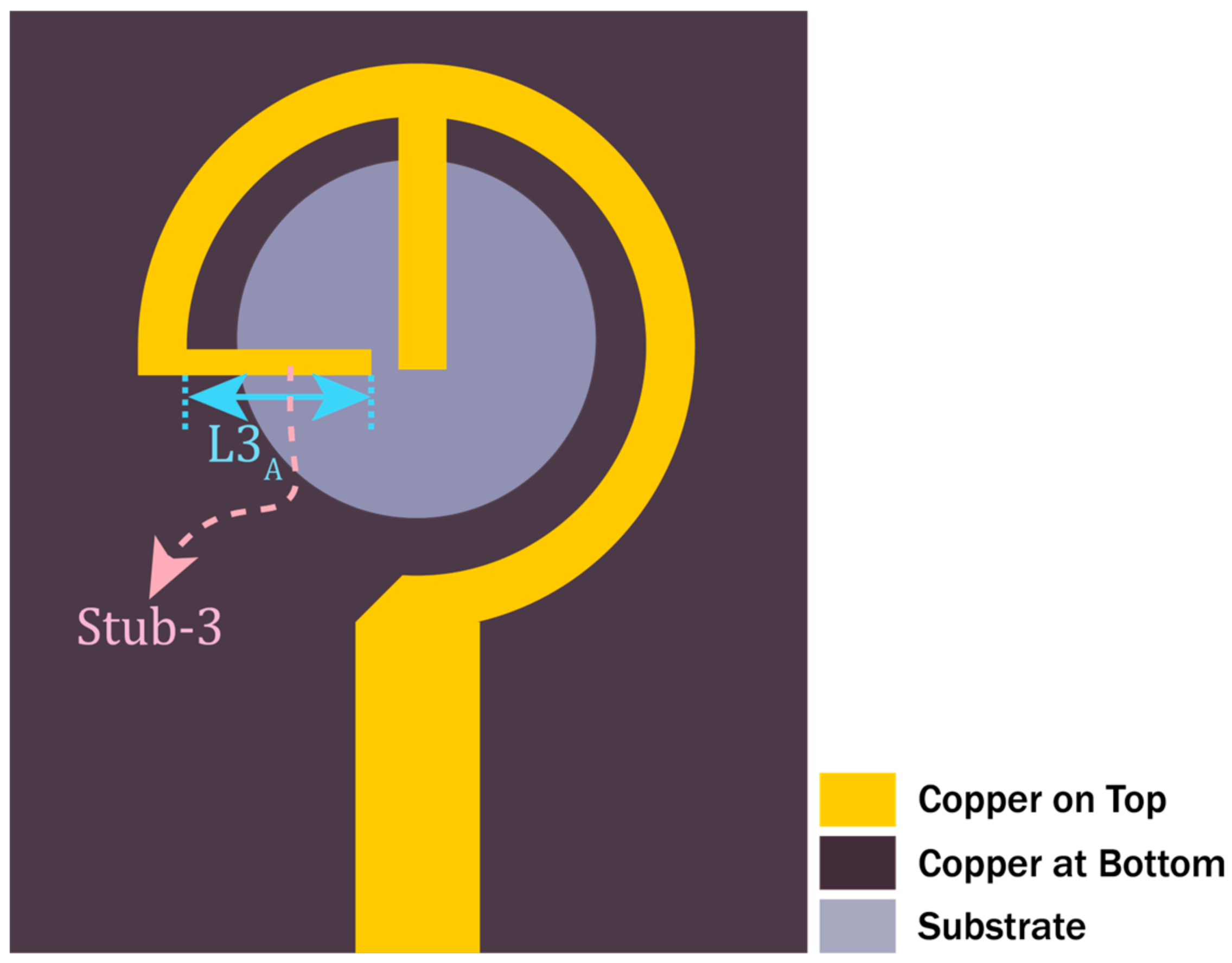
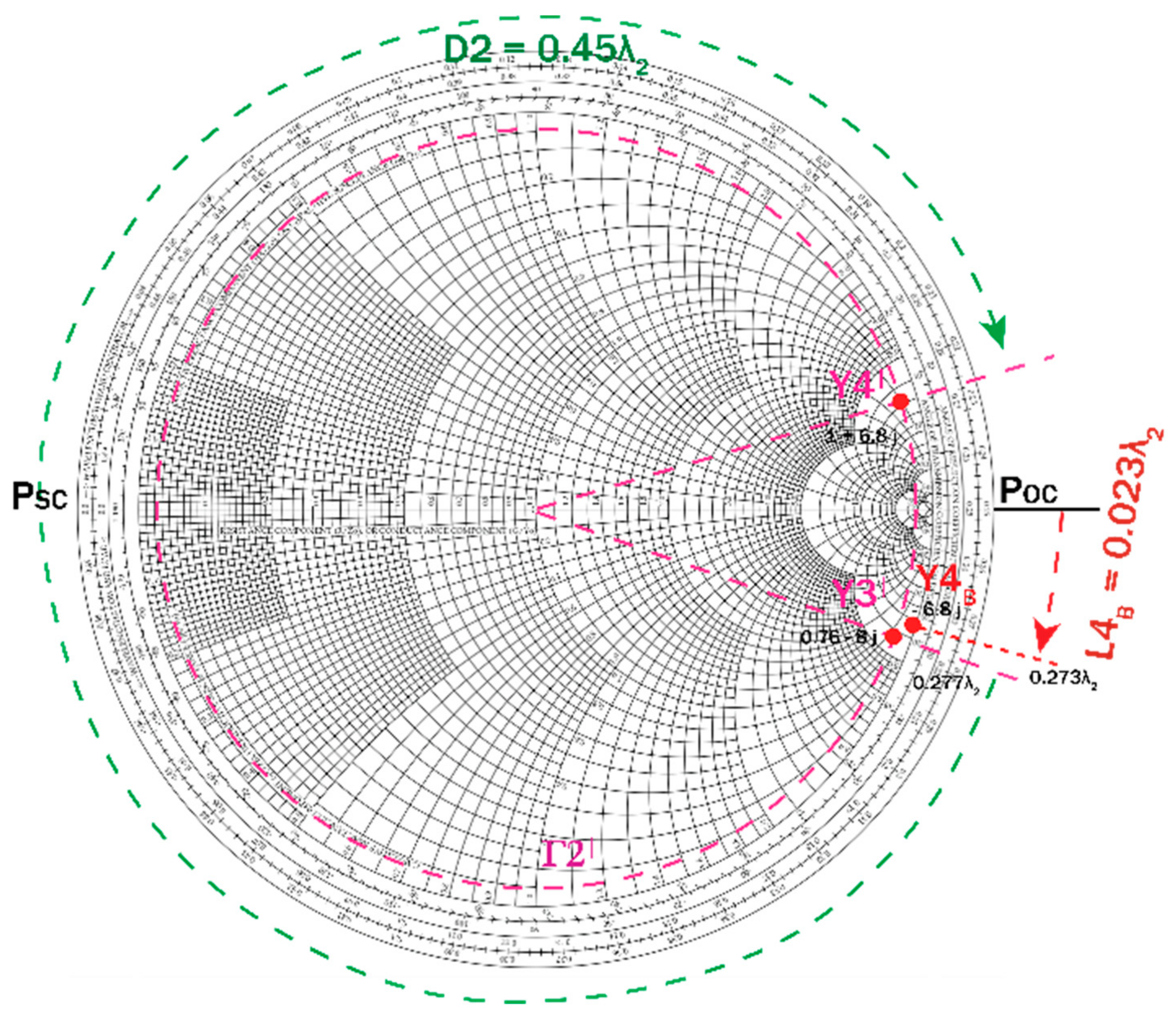
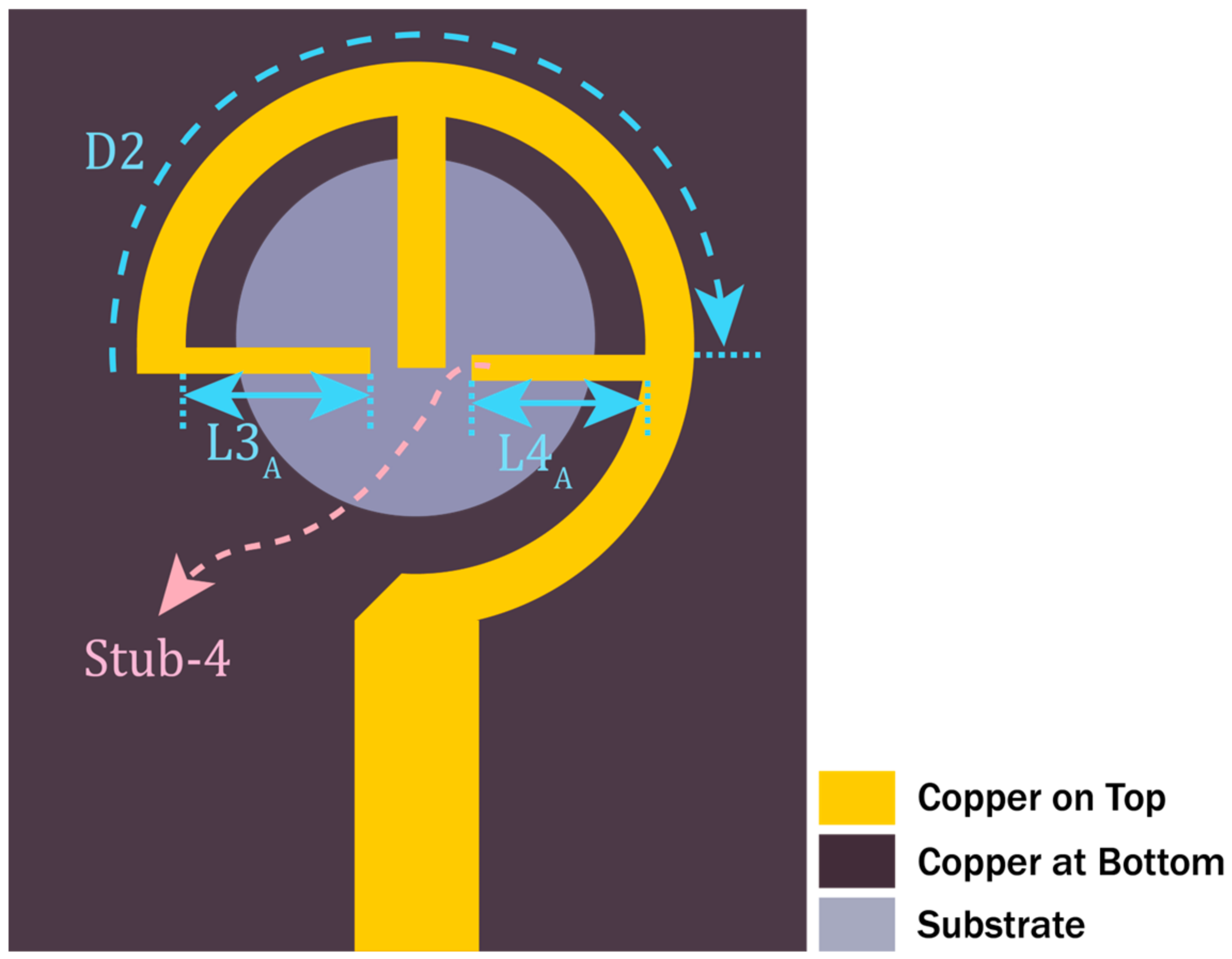
2.2. Matching Network (MN2) at 38 GHz (f2)
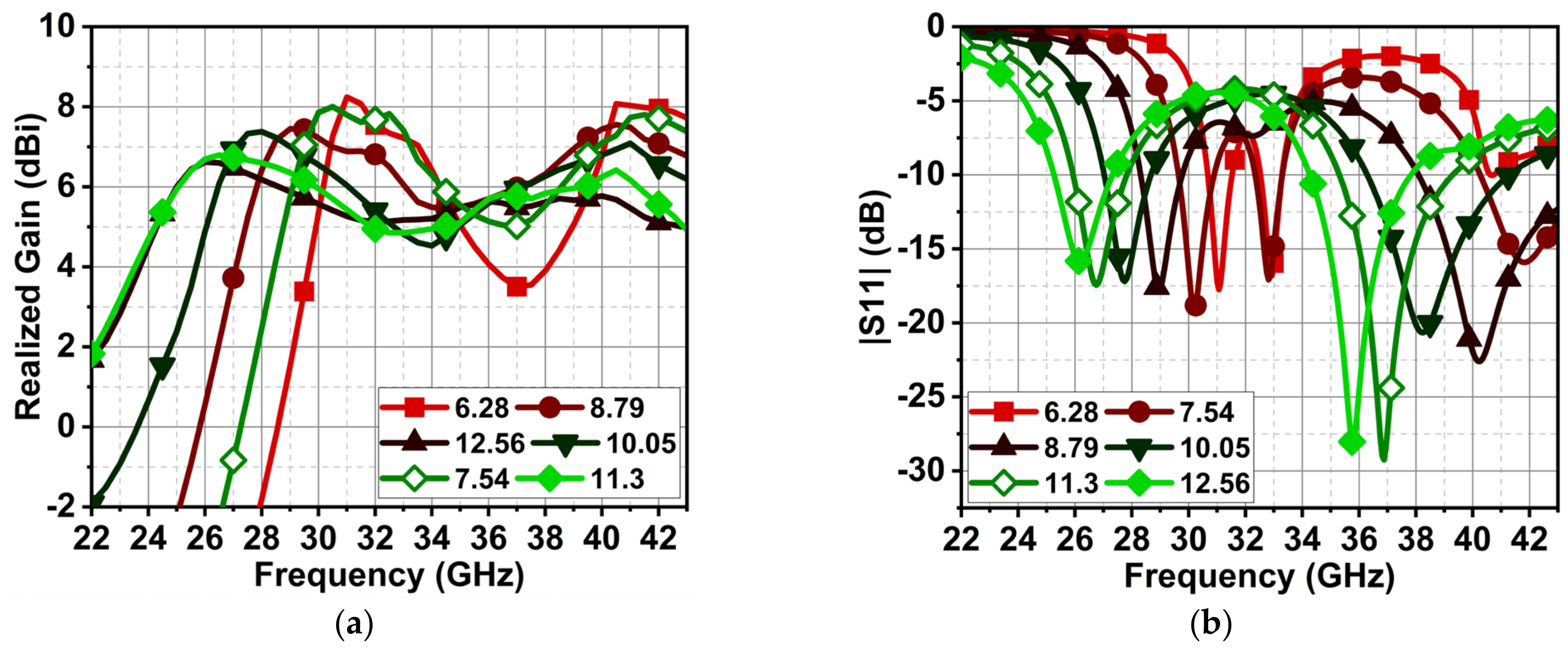
3. Parametric Analysis
3.1. Series Capacitance of MN1
3.2. Series Inductance of MN1
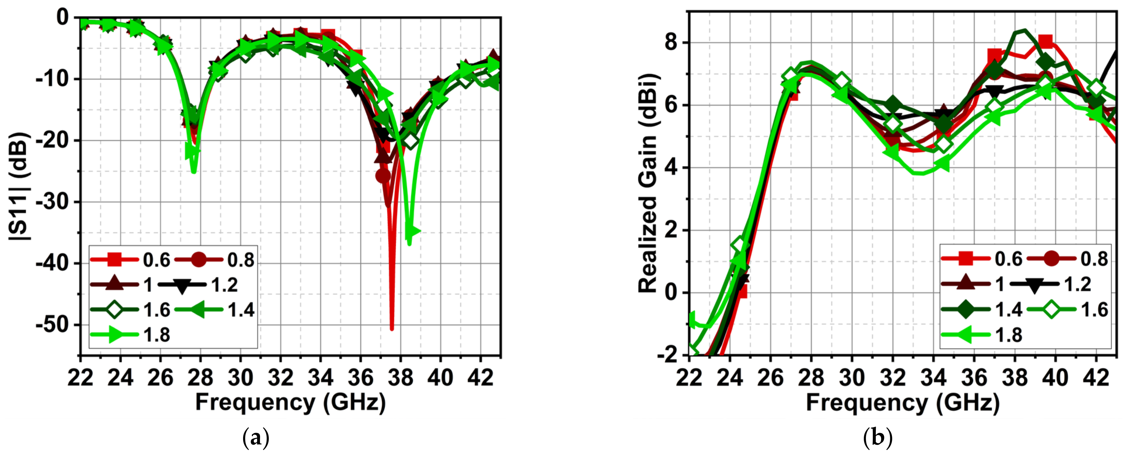
3.3. Shunt Inductance of MN2
3.4. Shunt Inductance of MN2
4. Results and Discussion
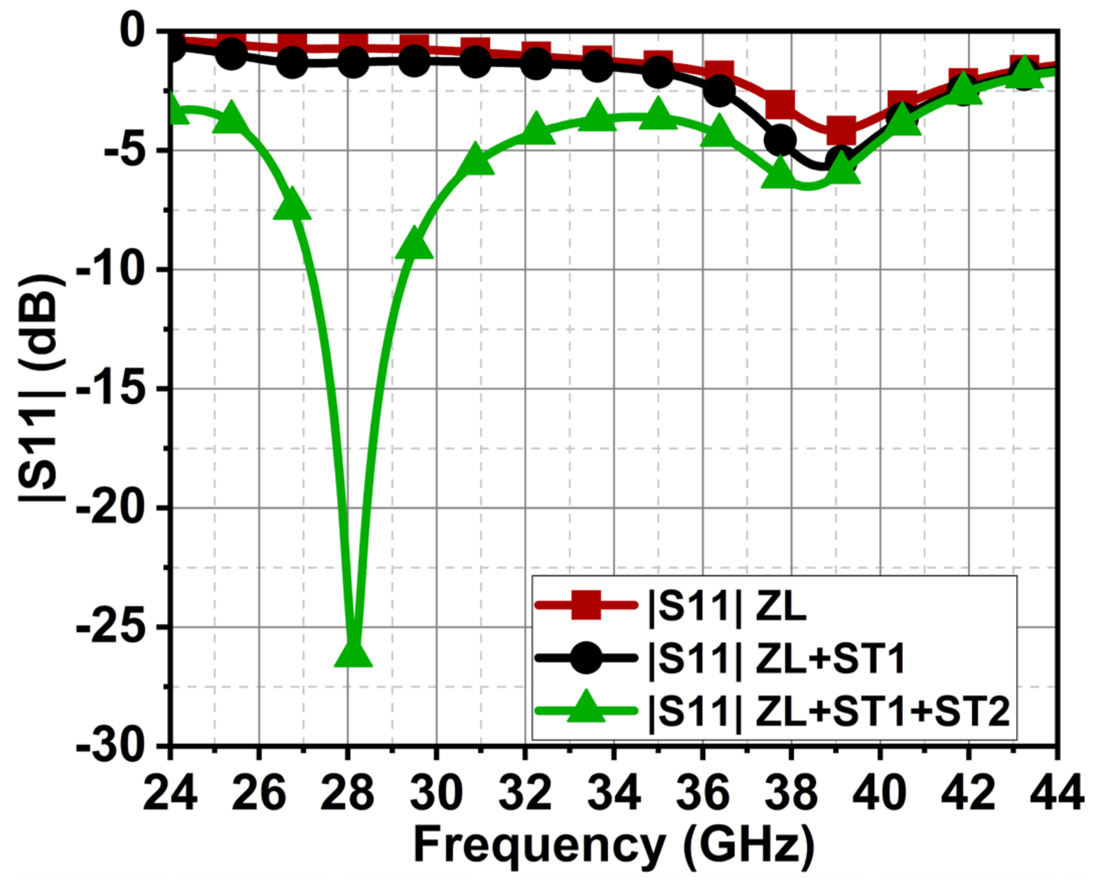
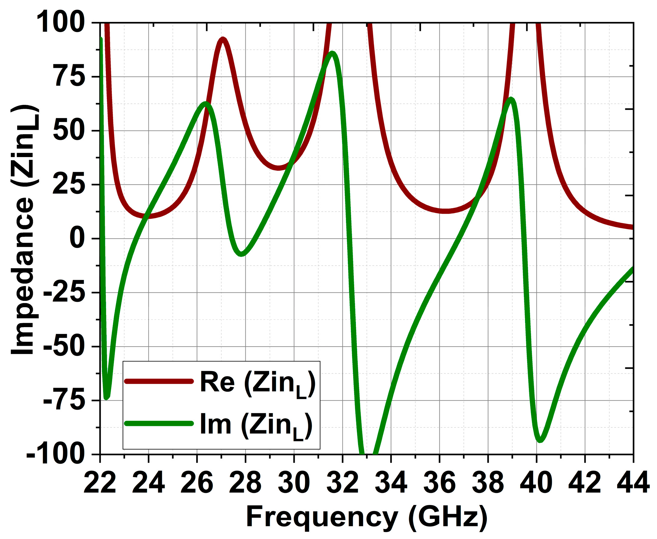
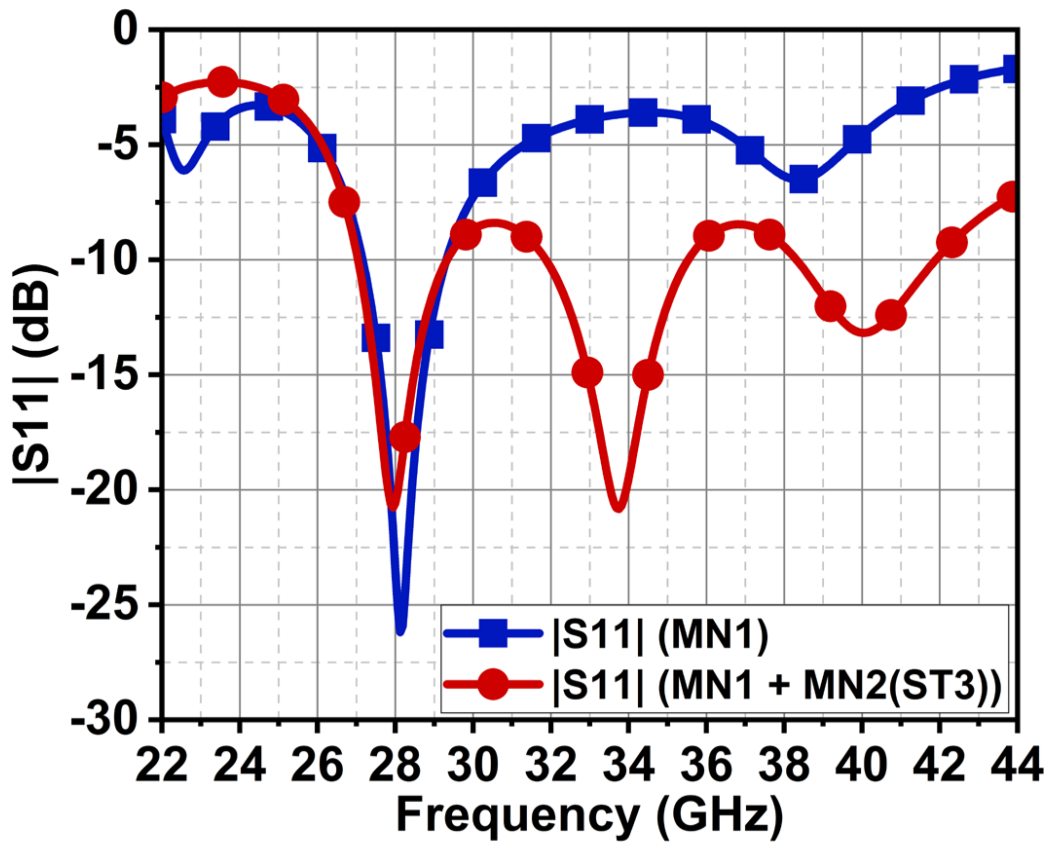
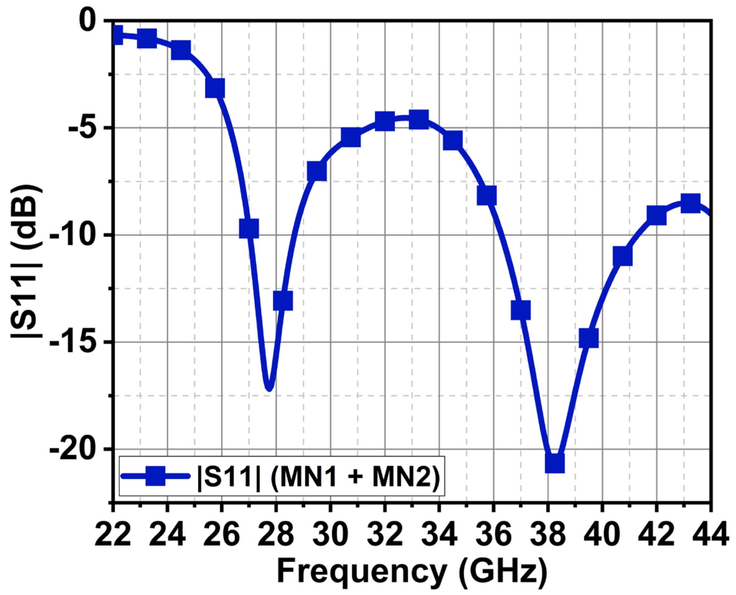
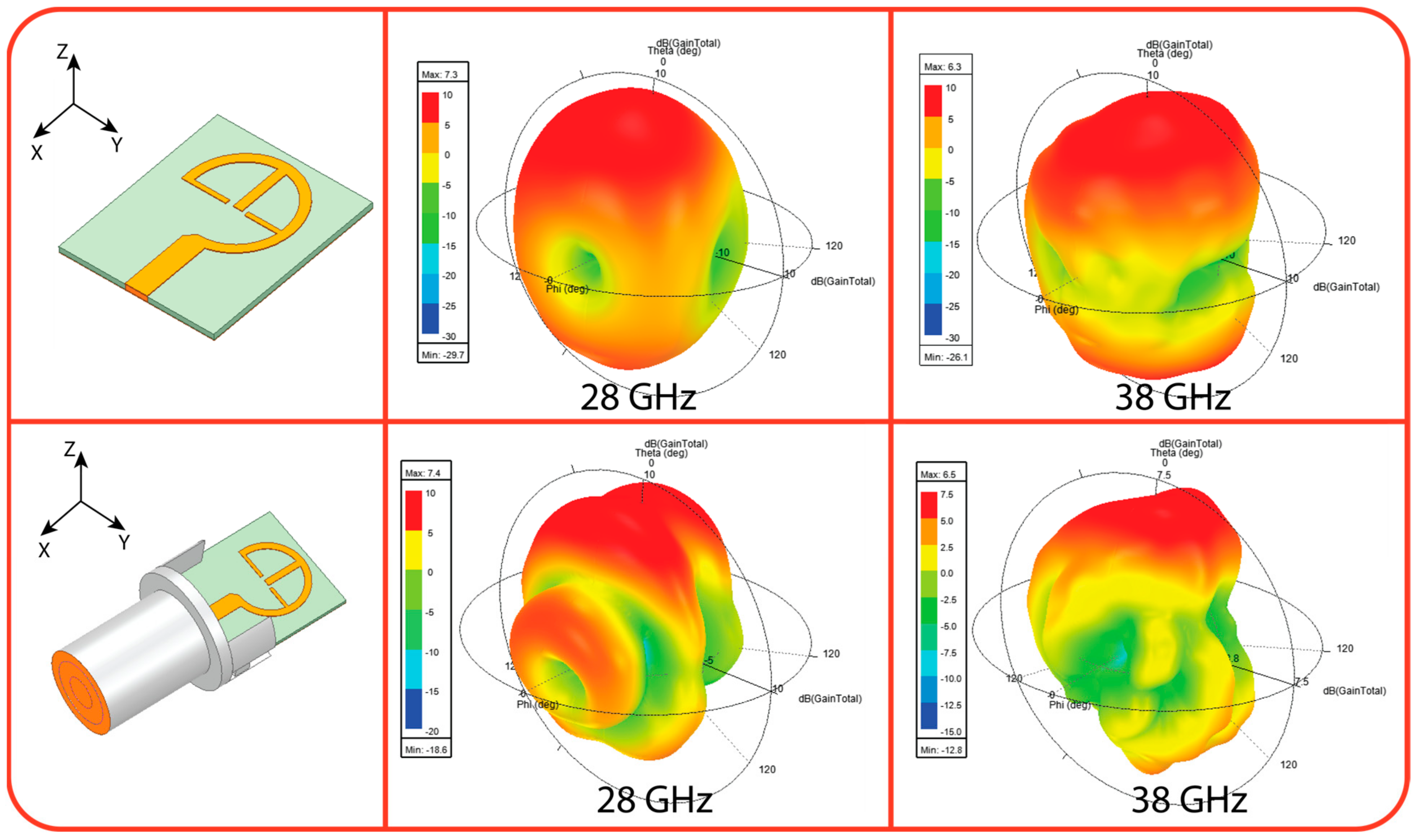
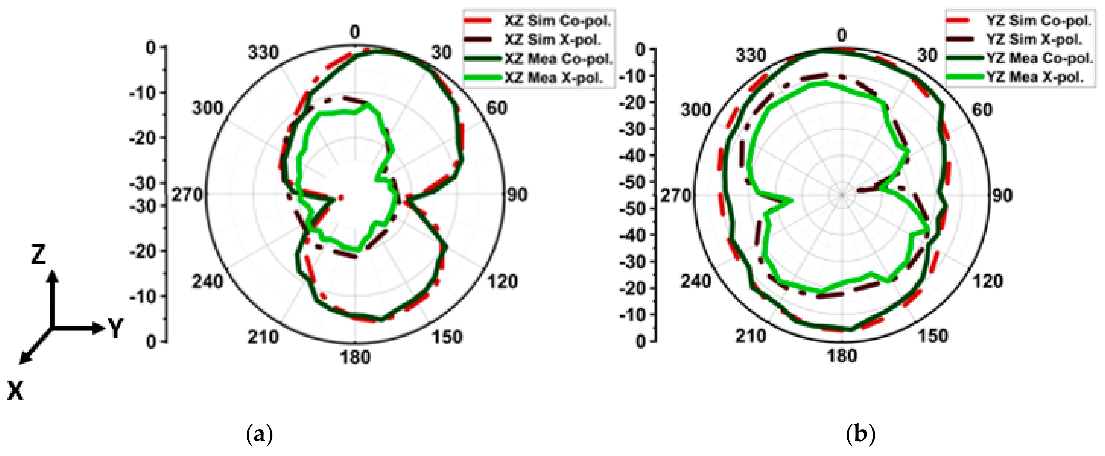
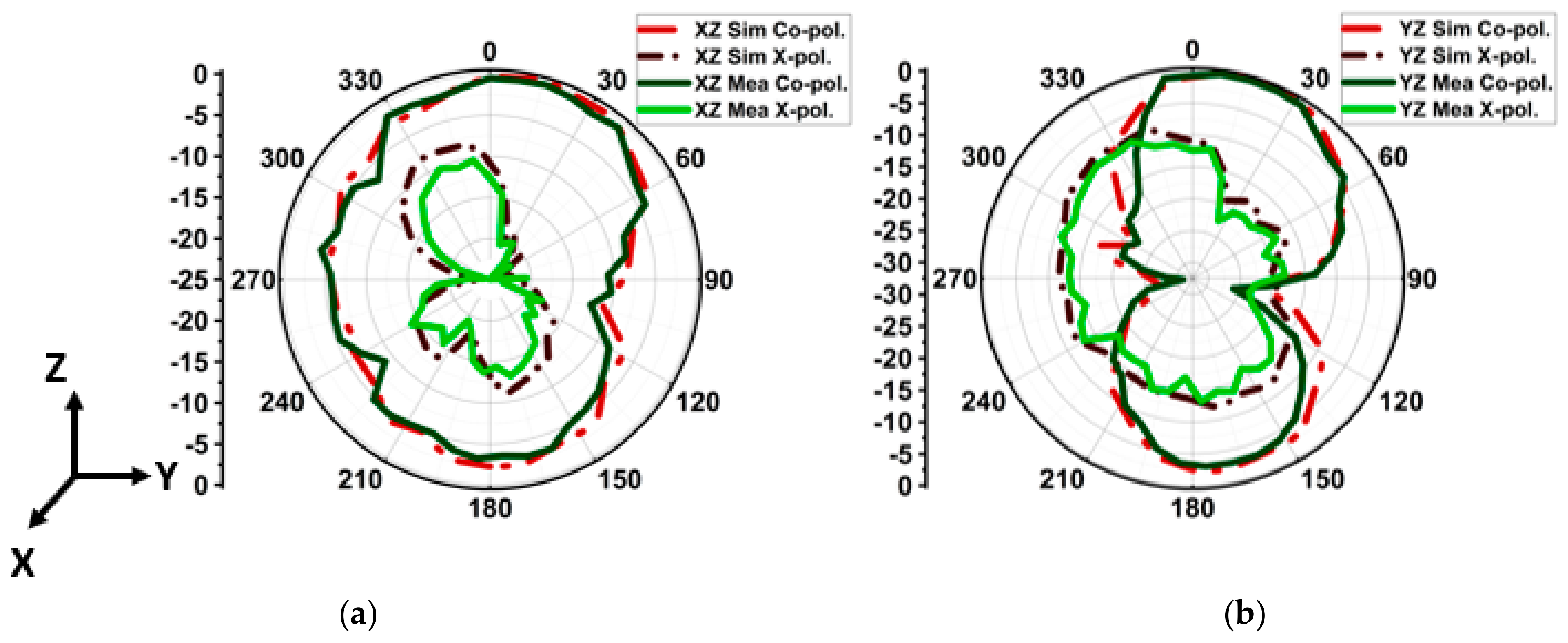
4.1. |S-Parameter| and Radiation Pattern
4.2. Comparative Analysis
5. Conclusions
Author Contributions
Funding
Institutional Review Board Statement
Informed Consent Statement
Data Availability Statement
Conflicts of Interest
References
- Ullah, U.; Kamboh, U.R.; Hossain, F.; Danish, M. Outdoor-to-Indoor and Indoor-to-Indoor Propagation Path Loss Modeling Using Smart 3D Ray Tracing Algorithm at 28 GHz mmWave. Arab. J. Sci. Eng. 2020, 45, 10223–10232. [Google Scholar] [CrossRef]
- Kohli, M.; Adhikari, A.; Avci, G.; Brent, S.; Dash, A.; Moser, J.; Hossain, S.; Kadota, I.; Garland, C.; Mukherjee, S.; et al. Outdoor-to-Indoor 28 GHz Wireless Measurements in Manhattan: Path Loss, Environmental Effects, and 90% Coverage. IEEE/ACM Trans. Netw. 2024, preprint. 1–16. [Google Scholar] [CrossRef]
- Ahamed, M.M.; Faruque, S. 5G Network Coverage Planning and Analysis of the Deployment Challenges. Sensors 2021, 21, 6608. [Google Scholar] [CrossRef]
- Singh, C.; Sharma, C.; Tripathi, S.; Sharma, M.; Agrawal, A. A Comprehensive Survey on Millimeter Wave Antennas at 30/60/120 GHz: Design, Challenges and Applications. Wirel. Pers. Commun. 2023, 133, 1547–1584. [Google Scholar] [CrossRef]
- Sun, G.-H.; Wong, H. A Planar Millimeter-Wave Antenna Array with a Pillbox-Distributed Network. IEEE Trans. Antennas Propagat. 2020, 68, 3664–3672. [Google Scholar] [CrossRef]
- Sun, Q.; Ban, Y.-L.; Lian, J.-W.; Liu, Y.; Nie, Z. Millimeter-Wave Multibeam Antenna Based on Folded C-Type SIW. IEEE Trans. Antennas Propagat. 2020, 68, 3465–3476. [Google Scholar] [CrossRef]
- Borhani-Kakhki, M.; Dadgarpour, A.; Antoniades, M.A.; Sebak, A.R.; Denidni, T.A. Magnetoelectric Dipole Antennas Loaded with Meta-Lens for 5G MIMO Pattern Diversity Applications. IEEE Trans. Antennas Propagat. 2022, 70, 7112–7117. [Google Scholar] [CrossRef]
- Dadgarpour, A.; Bayat-Makou, N.; Antoniades, M.A.; Kishk, A.A.; Sebak, A. A Dual-Polarized Magnetoelectric Dipole Array Based on Printed Ridge Gap Waveguide with Dual-Polarized Split-Ring Resonator Lens. IEEE Trans. Antennas Propagat. 2020, 68, 3578–3585. [Google Scholar] [CrossRef]
- Alibakhshikenari, M.; Virdee, B.S.; See, C.H.; Abd-Alhameed, R.A.; Falcone, F.; Limiti, E. High-Isolation Leaky-Wave Array Antenna Based on CRLH-Metamaterial Implemented on SIW with ±30° Frequency Beam-Scanning Capability at Millimetre-Waves. Electronics 2019, 8, 642. [Google Scholar] [CrossRef]
- Lee, K.F.; Tong, K.F. Microstrip Patch Antennas—Basic Characteristics and Some Recent Advances. Proc. IEEE 2012, 100, 2169–2180. [Google Scholar] [CrossRef]
- Liu, P.; Zhu, X.-W.; Zhang, Y.; Wang, X.; Yang, C.; Jiang, Z.H. Patch Antenna Loaded with Paired Shorting Pins and H-Shaped Slot for 28/38 GHz Dual-Band MIMO Applications. IEEE Access 2020, 8, 23705–23712. [Google Scholar] [CrossRef]
- Ramanujam, P.; Arumugam, C.; Venkatesan, R.; Ponnusamy, M. Design of Compact Patch Antenna with Enhanced Gain and Bandwidth for 5G Mm-wave Applications. IET Microw. Antennas Propag. 2020, 14, 1455–1461. [Google Scholar] [CrossRef]
- Farahat, A.E.; Hussein, K.F.A. Dual-Band (28/38 GHz) Wideband MIMO Antenna for 5G Mobile Applications. IEEE Access 2022, 10, 32213–32223. [Google Scholar] [CrossRef]
- Han, K.; Yan, Y.; Yan, Z.; Wang, C. Low-Profile Millimeter-Wave Metasurface-Based Antenna with Enhanced Bandwidth. Micromachines 2023, 14, 1403. [Google Scholar] [CrossRef]
- Kumar, A.; Kumar, A.; Kumar, A. Defected Ground Structure Based High Gain, Wideband and High Diversity Performance Quad-Element MIMO Antenna Array for 5G Millimeter-Wave Communication. Prog. Electromagn. Res. 2023, 101, 1–16. [Google Scholar] [CrossRef]
- Hoarau, C.; Corrao, N.; Arnould, J.-D.; Ferrari, P.; Xavier, P. Complete Design and Measurement Methodology for a Tunable RF Impedance-Matching Network. IEEE Trans. Microw. Theory Techn. 2008, 56, 2620–2627. [Google Scholar] [CrossRef]
- Lim, Y.; Tang, H.; Lim, S.; Park, J. An Adaptive Impedance-Matching Network Based on a Novel Capacitor Matrix for Wireless Power Transfer. IEEE Trans. Power Electron. 2014, 29, 4403–4413. [Google Scholar] [CrossRef]
- Kim, M.G.; Yoon, S.; Kim, H.H.; Shung, K.K. Impedance Matching Network for High Frequency Ultrasonic Transducer for Cellular Applications. Ultrasonics 2016, 65, 258–267. [Google Scholar] [CrossRef]
- Zhang, Y.H.; Spiegel, R.J.; Fan, Y.; Joines, W.T.; Liu, Q.H.; Da Xu, K. Design of a Stub-Loaded Ring-Resonator Slot for Antenna Applications. IEEE Trans. Antennas Propagat. 2015, 63, 517–524. [Google Scholar] [CrossRef]
- Cuneray, K.; Akcam, N.; Okan, T.; Arican, G.O. 28/38 GHz Dual-Band MIMO Antenna with Wideband and High Gain Properties for 5G Applications. AEU-Int. J. Electron. Commun. 2023, 162, 154553. [Google Scholar] [CrossRef]
- Islam, S.; Zada, M.; Yoo, H. Low-Pass Filter Based Integrated 5G Smartphone Antenna for Sub-6-GHz and Mm-Wave Bands. IEEE Trans. Antennas Propagat. 2021, 69, 5424–5436. [Google Scholar] [CrossRef]
- Alnemr, F.; Ahmed, M.F.; Shaalan, A.A. A Compact 28/38 GHz MIMO Circularly Polarized Antenna for 5 G Applications. J. Infrared Millim. Terahertz Waves 2021, 42, 338–355. [Google Scholar] [CrossRef]
- Chaudhary, S.; Kansal, A. Compact High Gain 28, 38 GHz Antenna for 5G Communication. Int. J. Electron. 2023, 110, 1028–1048. [Google Scholar] [CrossRef]
- Sabek, A.R.; Ali, W.A.E.; Ibrahim, A.A. Minimally Coupled Two-Element MIMO Antenna with Dual Band (28/38 GHz) for 5G Wireless Communications. J. Infrared Millim. Terahertz Waves 2022, 43, 335–348. [Google Scholar] [CrossRef]
- Kamal, M.M.; Yang, S.; Kiani, S.H.; Sehrai, D.A.; Alibakhshikenari, M.; Abdullah, M.; Falcone, F.; Limiti, E.; Munir, M. A Novel Hook-Shaped Antenna Operating at 28 GHz for Future 5G Mmwave Applications. Electronics 2021, 10, 673. [Google Scholar] [CrossRef]
- Esmail, B.A.F.; Koziel, S. Design and Optimization of Metamaterial-Based Dual-Band 28/38 GHz 5G MIMO Antenna with Modified Ground for Isolation and Bandwidth Improvement. Antennas Wirel. Propag. Lett. 2023, 22, 1069–1073. [Google Scholar] [CrossRef]
- Kiouach, F.; Aghoutane, B.; Das, S.; Islam, T.; El Ghzaoui, M.; Madhav, B. A Dual Operating (27/38 GHz) High Performance 2 × 4 MIMO Antenna Array for 5G New Radio Applications. Phys. Scr. 2023, 98, 115504. [Google Scholar] [CrossRef]
- Islam, S.; Zada, M.; Yoo, H. Highly Compact Integrated Sub-6 GHz and Millimeter-Wave Band Antenna Array for 5G Smartphone Communications. IEEE Trans. Antennas Propagat. 2022, 70, 11629–11638. [Google Scholar] [CrossRef]
- Khabba, A.; Amadid, J.; Ibnyaich, S.; Zeroual, A. Pretty-Small Four-Port Dual-Wideband 28/38 GHz MIMO Antenna with Robust Isolation and High Diversity Performance for Millimeter-Wave 5G Wireless Systems. Analog. Integr. Circ. Signal Process 2022, 112, 83–102. [Google Scholar] [CrossRef]
- Chan, K.-C.; Harter, A. Impedance matching and the Smith chart-The fundamentals. RF Design 2000, 23, 52–66. [Google Scholar]
- Ida, N. Engineering Electromagnetics; Springer International Publishing: Cham, Switzerland, 2015; ISBN 978-3-319-07805-2. [Google Scholar]
- Caloz, C.; Okabe, H.; Iwai, T.; Itoh, T. A Simple and Accurate Model for Microstrip Structures with Slotted Ground Plane. IEEE Microw. Wireless Compon. Lett. 2004, 14, 127–129. [Google Scholar] [CrossRef]
- Lyu, H.; Wang, J.; La, J.-H.; Chung, J.M.; Babakhani, A. An Energy-Efficient Wirelessly Powered Millimeter-Scale Neurostimulator Implant Based on Systematic Codesign of an Inductive Loop Antenna and a Custom Rectifier. IEEE Trans. Biomed. Circuits Syst. 2018, 12, 1131–1143. [Google Scholar] [CrossRef] [PubMed]
- Li, H.; Wang, B.; Guo, L.; Xiong, J. Efficient and Wideband Implantable Antenna Based on Magnetic Structures. IEEE Trans. Antennas Propagat. 2019, 67, 7242–7251. [Google Scholar] [CrossRef]
- Alrawashdeh, R.S.; Huang, Y.; Kod, M.; Abu Bakar Sajak, A. A Broadband Flexible Implantable Loop Antenna with Complementary Split Ring Resonators. Antennas Wirel. Propag. Lett. 2015, 14, 1506–1509. [Google Scholar] [CrossRef]
- Farooq, U.; Rather, G.M. A Miniaturised Ka/V Dual Band Millimeter Wave Antenna for 5G Body Centric Network Applications. Alex. Eng. J. 2022, 61, 8089–8096. [Google Scholar] [CrossRef]
- Guo, Y.Q.; Pan, Y.M.; Zheng, S.Y.; Lu, K. A Singly-Fed Dual-Band Microstrip Antenna for Microwave and Millimeter-Wave Applications in 5G Wireless Communication. IEEE Trans. Veh. Technol. 2021, 70, 5419–5430. [Google Scholar] [CrossRef]
- Hussain, M.; Awan, W.A.; Ali, E.M.; Alzaidi, M.S.; Alsharef, M.; Elkamchouchi, D.H.; Alzahrani, A.; Fathy Abo Sree, M. Isolation Improvement of Parasitic Element-Loaded Dual-Band MIMO Antenna for Mm-Wave Applications. Micromachines 2022, 13, 1918. [Google Scholar] [CrossRef] [PubMed]
- Sadeghi-Marasht, S.; Sharawi, M.S.; Zhu, A. Dual-Band Circularly Polarized Antenna Array for 5G Millimeter-Wave Applications. IEEE Open J. Antennas Propag. 2022, 3, 314–323. [Google Scholar] [CrossRef]
- Ali Esmail, B.; Koziel, S. High Isolation Metamaterial-Based Dual-Band MIMO Antenna for 5G Millimeter-Wave Applications. AEU-Int. J. Electron. Commun. 2023, 158, 154470. [Google Scholar] [CrossRef]
- Aboualalaa, M.; Mansour, I. Dual-Band End-Fire Four-Element MIMO Antenna Array Using Split-Ring Structure for Mm-Wave 5G Applications. IEEE Access 2023, 11, 57383–57390. [Google Scholar] [CrossRef]
- Ghosh, S.; Baghel, G.S.; Swati, M.V. A Low-Profile, High Gain, Dual-Port, Planar Array Antenna for Mm-Wave Powered 5G IoT Systems. AEU-Int. J. Electron. Commun. 2022, 155, 154354. [Google Scholar] [CrossRef]
- Khan, D.; Ahmad, A.; Choi, D.-Y. Dual-Band 5G MIMO Antenna with Enhanced Coupling Reduction Using Metamaterials. Sci. Rep. 2024, 14, 96. [Google Scholar] [CrossRef] [PubMed]


| Stub-1 Length (L1B) | Slot Radius (Gs) |
|---|---|
| 6.28 | 1 |
| 7.54 | 1.2 |
| 8.79 | 1.4 |
| 10.05 | 1.6 |
| 11.3 | 1.8 |
| 12.56 | 2 |
| Ref. | Dimensions in mm | Dimensions in λ | Resonance | Bandwidth (GHz) at |S11| > 10 dB | Realized Gain (dBi) | Impedance Matching Technique |
|---|---|---|---|---|---|---|
| [37] | 26 | 24–28.5 | 12 * | Stub-loaded + linear Array | ||
| [36] | 33.5/60.8 | 33–34.2/60–60.2 | 6.6/7.1 | Arbitrary slot-loading | ||
| [38] | 30/39 | 27.5–32/37–41.5 | 7/7.5 ** | Arbitrary (parametric) slot + stub loading | ||
| [39] | 28/37 | 27–28.7/35–40 | 6.8/6.5 | Parasitic element + L-stub | ||
| [40] | 28/38 | 22–30/36.8–40 | 5.8 ** | Arbitrary slots + stub | ||
| [41] | 25/29 | 23–25.5/28.4–32 | 7 | λ/4 transformer + SRRs | ||
| [42] | 28 | 27.4–28.8 | 6.1 | λ/4 transformer | ||
| [43] | 27.5/38 | 25.2–29.4/36–40 | 6 | Arbitrary slots + stub | ||
| Prop. | 28/38 | 26.7–28.9/36.1–41.5 | 7.2 | Double-stub matching with dual-matching network |
Disclaimer/Publisher’s Note: The statements, opinions and data contained in all publications are solely those of the individual author(s) and contributor(s) and not of MDPI and/or the editor(s). MDPI and/or the editor(s) disclaim responsibility for any injury to people or property resulting from any ideas, methods, instructions or products referred to in the content. |
© 2024 by the authors. Licensee MDPI, Basel, Switzerland. This article is an open access article distributed under the terms and conditions of the Creative Commons Attribution (CC BY) license (https://creativecommons.org/licenses/by/4.0/).
Share and Cite
Bhadravathi Ghouse, P.S.; Kumar, P.; Mane, P.R.; Pathan, S.; Ali, T.; Boulogeorgos, A.-A.A.; Anguera, J. Dual-Band Antenna at 28 and 38 GHz Using Internal Stubs and Slot Perturbations. Technologies 2024, 12, 84. https://doi.org/10.3390/technologies12060084
Bhadravathi Ghouse PS, Kumar P, Mane PR, Pathan S, Ali T, Boulogeorgos A-AA, Anguera J. Dual-Band Antenna at 28 and 38 GHz Using Internal Stubs and Slot Perturbations. Technologies. 2024; 12(6):84. https://doi.org/10.3390/technologies12060084
Chicago/Turabian StyleBhadravathi Ghouse, Parveez Shariff, Pradeep Kumar, Pallavi R. Mane, Sameena Pathan, Tanweer Ali, Alexandros-Apostolos A. Boulogeorgos, and Jaume Anguera. 2024. "Dual-Band Antenna at 28 and 38 GHz Using Internal Stubs and Slot Perturbations" Technologies 12, no. 6: 84. https://doi.org/10.3390/technologies12060084