Article

Perovskite Solar Cells and Thermoelectric Generator Hybrid Array Feeding a Synchronous Reluctance Motor for an Efficient Water Pumping System

by
Alaa A. Zaky
1,2,3,*,
Mohamed N. Ibrahim
1,4,5,
Ibrahim B. M. Taha
6,
Bedir Yousif
1,7,
Peter Sergeant
4,5,
Evangelos Hristoforou
2 and
Polycarpos Falaras
3
1
Electrical Engineering Department, Faculty of Engineering, Kafrelsheikh University, Kafr El-Sheikh 33511, Egypt
2
School of Electrical and Computer Engineering, National Technical University of Athens (NTUA), 15780 Athens, Greece
3
Institute of Nanoscience and Nanotechnology, National Center for Scientific Research “Demokritos”, Aghia Paraskevi Attikis, 15341 Athens, Greece
4
Department of Electromechanical, Systems and Metal Engineering, Ghent University, 9000 Ghent, Belgium
5
FlandersMake@UGent—Corelab EEDT-MP, 3001 Leuven, Belgium
6
Electrical Engineering Department, College of Engineering, Taif University, P.O. Box 11099, Taif 21944, Saudi Arabia
7
Electrical Engineering Department, Faculty of Engineering and Information Technology, Onaizah Colleges, Onaizah 56447, Saudi Arabia
*
Author to whom correspondence should be addressed.
Mathematics 2022, 10(14), 2417; https://doi.org/10.3390/math10142417
Submission received: 7 June 2022 / Revised: 8 July 2022 / Accepted: 8 July 2022 / Published: 11 July 2022

Abstract

:
Nowadays, water pumping systems based on photovoltaics as a source of electricity have widely increased. System cost and efficiency still require enhancement in order to spread their application. Perovskite solar cells (PSCs) are the most hopeful third-generation photovoltaic for replacing the silicon-based photovoltaic thanks to their high power conversion efficiency, reaching 25.8%; tunable band-gap; long diffusion length; low fabrication temperature; and low cost. In this work, for the first time, we proposed a high-power-density hybrid perovskite solar cell thermoelectric generator (TEG) array for feeding a synchronous reluctance motor (SynRM) driving a water pump for use in an irrigation system. A control technique was used to achieve two functions. The first function was driving the motor to obtain the maximum torque/ampere. The second was harvesting the maximum perovskite solar cell array output power on the basis of the maximum power point tracking (MPPT) algorithm using the perturbation and observation approach. Thus, the proposed hybrid perovskite solar cell–thermoelectric generator feeds the motor via an inverter without DC–DC converters or batteries. Accordingly, the short life problems and the high replacement cost are avoided. The proposed complete system was simulated via the MATLAB package. Moreover, a complete laboratory infrastructure was constructed for testing the proposed high-power-density hybrid perovskite solar cell–TEG array for the water pumping system. The results revealed that using the high-power-density hybrid perovskite solar cell–TEG array, both the motor’s output power and the pump’s flow rate were improved by 11% and 14%, respectively, compared to only using the perovskite solar cell array. Finally, both the simulation and experimental results proved the high-performance efficiency of the system in addition to showing its system complexity and cost reduction.

1. Introduction

Recently, renewable energy sources have been widely used to alternate traditional energy sources. This use is for helping in global warming reduction and overcoming the exhaustion of fossil fuels [1]. One of the most promising renewable energy sources is solar energy, where the light is directly converted to electric energy via the photovoltaic (PV) concept. Solar energy as an electric energy source has some merits, i.e., no pollution, no noise, environmentally friendly, low maintenance cost, and zero fuel cost. However, the PV technique for electricity production still requires a large amount of enhancement in both cost and efficiency, and some studies have investigated these issues [2,3].
The PV system is a good solution for the electricity needed in the electric grid’s remote areas. In this context, a PV standalone system can be used for lighting and pumping systems for crop irrigation. The silicon PV system efficiency is up to 14%, and its output varies with irradiation conditions. Thus, it always needs maximum power point tracking to keep the system working at the maximum power point [3]. Heat is produced during the PV system working, leading to output reduction. To solve this problem, a cooling system is necessary. Another solution for overcoming the heat problem is to convert this heat into electricity and support the PV system output via a thermoelectric generator (TEG). A hybrid PV–TEG system uses TEG in the backside of the PV to convert heat to electricity [3,4,5,6].
Concerning the photovoltaic–TEG hybrid system, some research in the literature discussed its use; however, it is clear from these studies that the system has a DC–DC converter for the PV and another one for the TEG, leading to system complexity and cost increase [6]. The total output power and efficiency in the case of the hybrid PV–TEG are higher than PV only [7]. Some studies in the literature reported that the motor in the pumping system’s inverter could be used in the PV power output maximization. The PV maximum power is obtained via the electric motor inverter controlling; thus, there is no need for the DC–DC converter, resulting in system cost and complexity reduction [8,9,10].
In this context, PSCs are one of the most common third-generation photovoltaics with a promising efficiency, reaching up to 25.8% until now [11,12,13,14,15,16,17,18,19,20]. PSCs are fabricated at low temperatures and at low costs.
Both DC and different AC motors were used in a PV-based water pumping system. The DC motors are rarely used because of the high cost, since this type has brushes and a commutator, and both need maintenance, which increases their running cost. Moreover, AC motors have been used as induction motors, switched reluctance motors, permeant magnet synchronous motors, and recently synchronous reluctance motors (SynRM) [10]. Each motor from the AC motors has its merits and demerits due to the size, the cost, the converter, and the control issues. SynRM is used in water pumping systems and other applications that need variable speed drive efficiently because the rotor of this motor does not have any magnets and windings/cages. Moreover, the SynRM stator is the same as the conventional electric machines (e.g., induction motor) stator and uses the same drive system. As a result, SynRM has a low cost and higher efficiency than the other AC motors [21,22].
In previous studies, some research groups have studied the hybrid photovoltaic and TEG array [1,4,5,7]. In [1], the study presented a hybrid photovoltaic–TEG system feeding a resistive load and battery. This study has two DC–DC converters that require two controllers for obtaining the maximum output power from the hybrid system. This resulted in both system complexity and cost increase. In [5], the study presented the theoretical assessment of the hybrid system using photovoltaic and TEG commercial data. In [7], the hybrid system performance was investigated on the basis of the thermodynamic approach. Where various conditions and constructions of the hybrid system have been examined, as a result, the hybrid system’s power is higher, and its efficiency is high. It is well known that MPPPT is necessary for harvesting the maximum power in photovoltaic systems, and this requires using DC–DC converters. The DC–DC converters track the MPP by changing the duty ratio. PSCs production costs are very low in the case of perovskite-based devices compared to silicon-based devices since 1 watt costs almost 10–20 cents; in contrast, 1 watt in silicon-based cells costs almost 75 cents, while 1 watt produced by TEG costs 70 cents [23,24,25,26]. On this basis, the PSCs are proposed in this work to be used in water pumping systems instead of silicon solar cells.
In this work, for the first time, a proposed hybrid perovskite solar cell–TEG array was used for feeding a SynRM applied in water pumping for irrigation purposes. This study investigated the proposed system theoretically via MATLAB simulation and was validated experimentally via a lab test bench. The proposed system has no DC–DC converts and batteries, leading to both system cost and complexity reduction. The hybrid perovskite solar cells–TEG arrays maximum power point tracking is implemented via a suggested control approach for the SynRM inverter. Ultimately, the performance of the proposed system is enhanced, which possibly will pave the way for use as a hopeful solution for remote area irrigation via a water pumping system. This work is structured as follows: Section 2 denotes the proposed system components of the proposed PV water pumping system; the proposed control strategy is discussed in Section 3; the performance of the suggested system is reported in Section 4; the economic analysis is reported in Section 5; the laboratory bench test for results experimental validation is presented in Section 6; while Section 7 denotes the study output and conclusions.

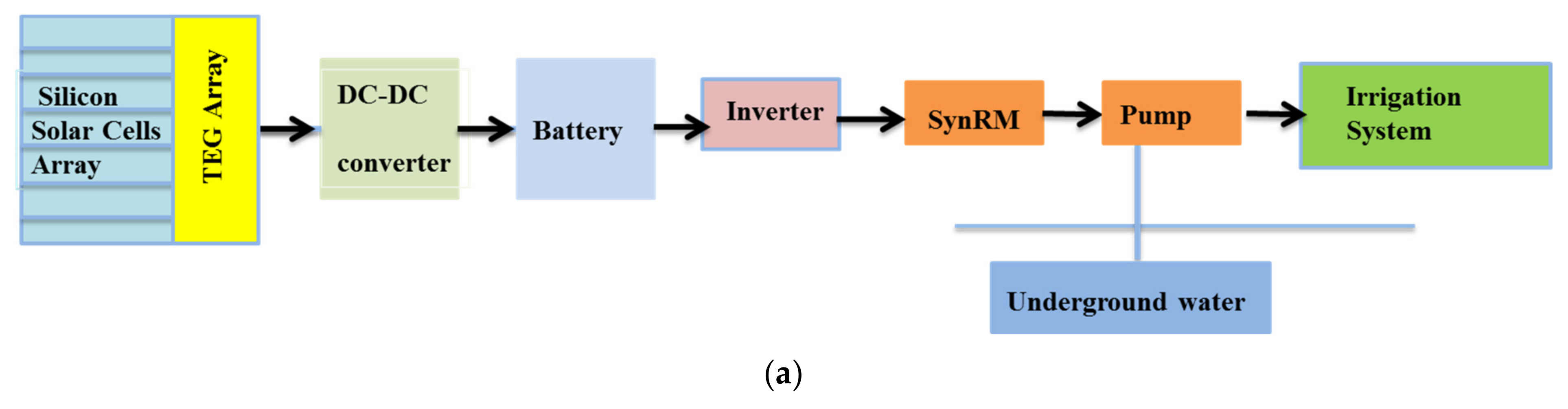
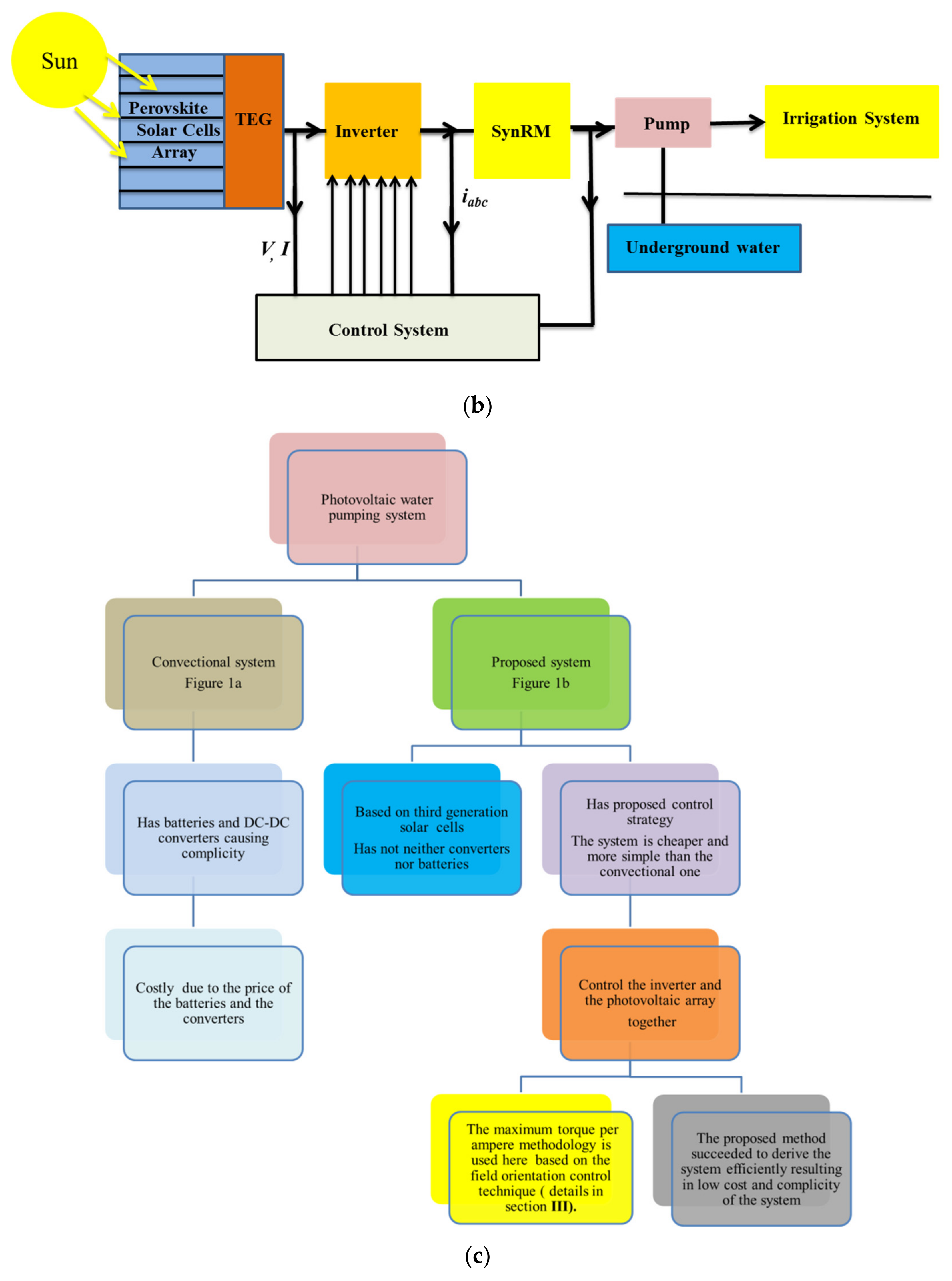
2. The Proposed System Components

Figure 1a shows the conventional photovoltaic water pumping system, while Figure 1b presents the suggested system, and it consists of a perovskite solar cell array, TEG modules, a three-phase inverter (voltage source), a three-phase SynRM, pump, and a control method. As shown in Figure 1a,b, the modules of the TEG are placed at the perovskite solar cell array backside. The modeling of each system component is mandatory for the system performance investigation. The system component modeling is described below [21,22]. Figure 1b shows no storage batteries and DC–DC converters in the proposed system, leading to cost reduction. The flow chart of the proposed methodology used to control and derive the proposed system is shown in Figure 1c.

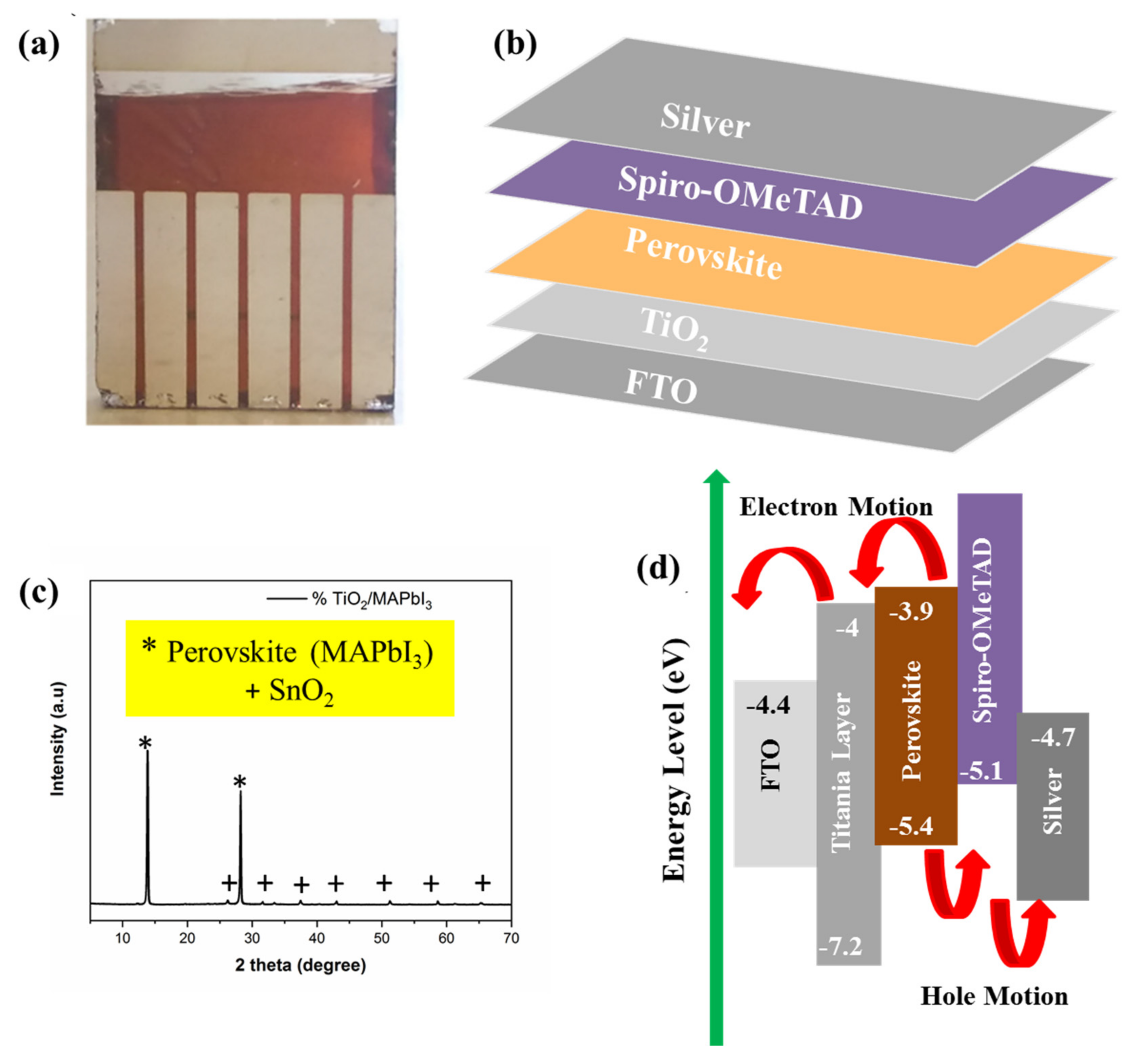
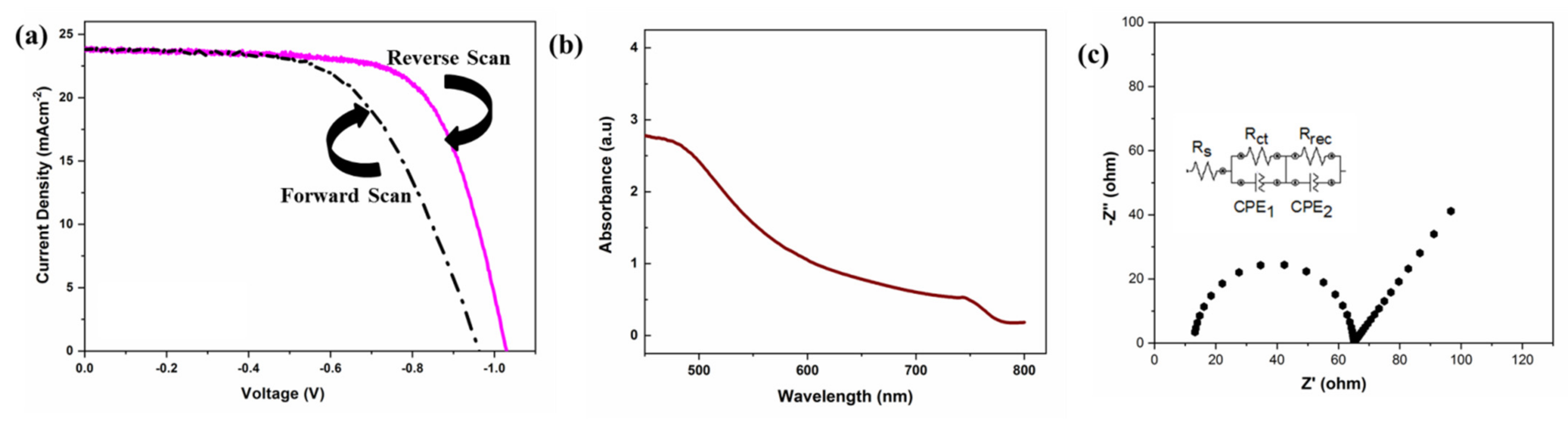
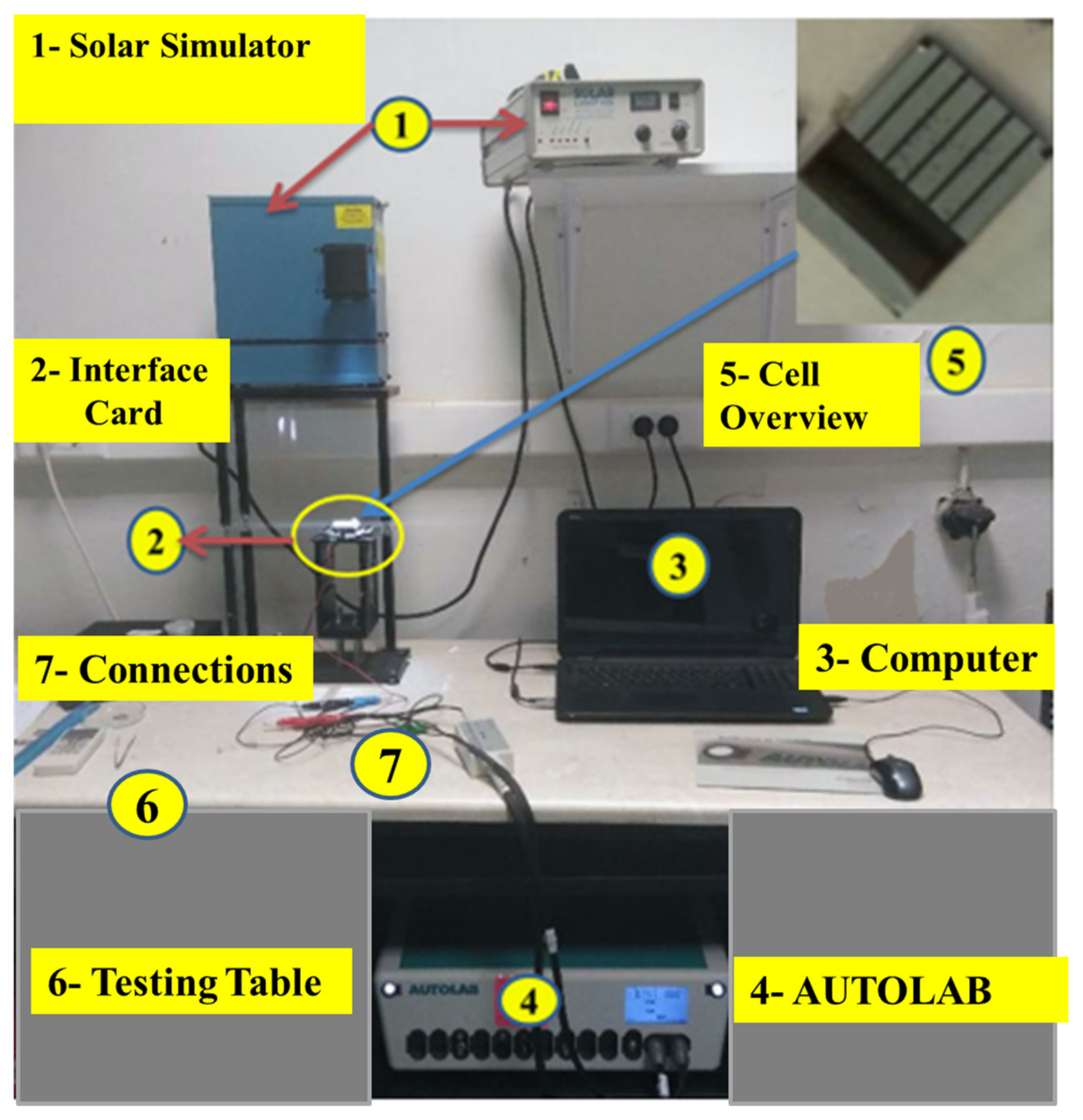
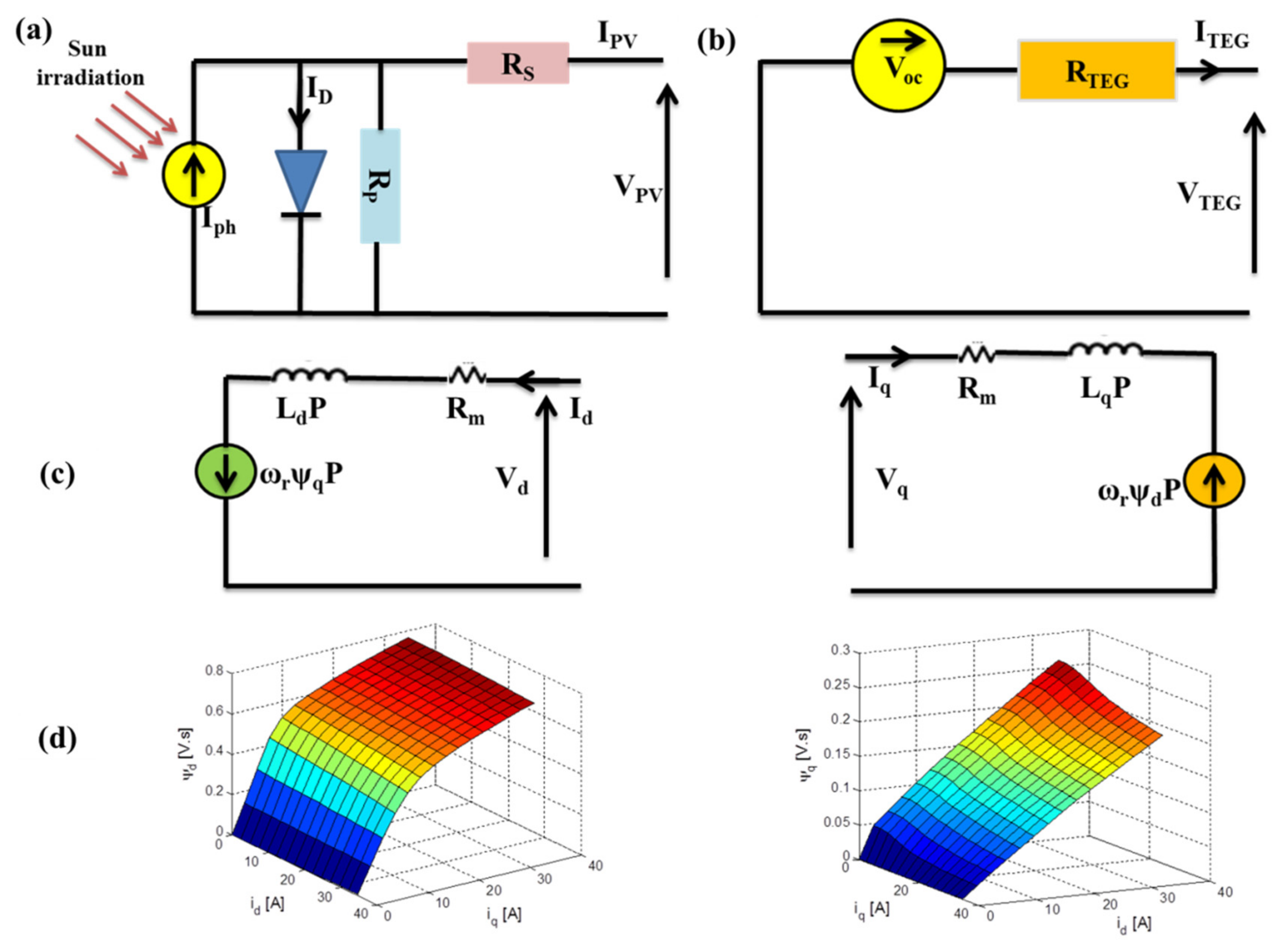
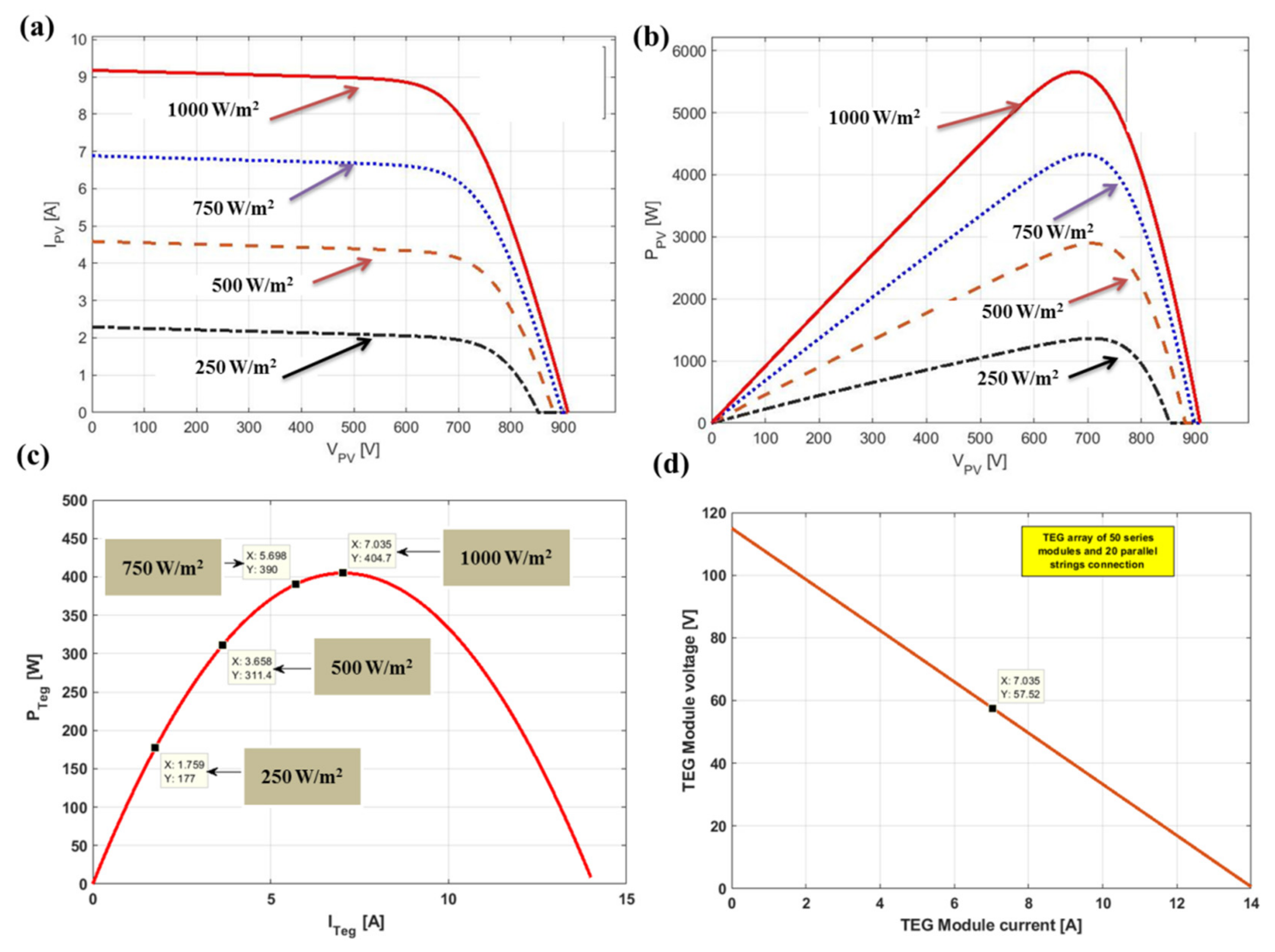
2.1. Perovskite Solar Cell Fabrication and Modeling

The PSC device used in this study consists of four layers over fluorine tine oxide (FTO) conductive glasses, namely, the layer for transporting electrons (ETL), the perovskite absorber layer (active layer), the layer for transporting holes (HTL), and the electrodes layer (contact layer). The complete fabricated device in the lab is shown in Figure 2a. In contrast, the device schematic diagram is shown in Figure 2b, and all the device layers are deposited over each other. The device is fabricated and characterized as described below.
Layer 1 (ETL): Used for transporting the electrons and formed via spin coating (2000 rpm for 1 min); ethanolic solution of titanium (IV) is opropoxide, having a small amount of HCl over the cleaned FTO conductive substrates, which was cleaned by a three-stage 15 min sonication path with Hellmanex, then 2-propanol, and finally acetone, followed by a 15 min UV ozone treatment for dust removal. After ETL deposition, the substrates were left for 10 min at 150 °C to dry, then calcinated at 500 °C for 45 min with 5 °C·min−1 as a temperature ramp rate.
Layer 2 (Perovskite absorber layer): This layer is the active layer in the device where the light is absorbed; the perovskite material produces an electron–hole pair inside the layer, the electrons move through the ETL, and the holes move through the HTL. The perovskite layer was formed via spin coating the perovskite solution over the ETL layer at 2000 rpm for 45 s in the glove box. The MAPbI3 perovskite solution consists of lead acetate as a source of lead and 40 wt% methylammonium iodide mixed in anhydrous DMF, then hypophosphorous acid was added to the solution. After the deposition via spin-coating, the perovskite films were left for 10 min at room temperature to dry, then annealed over a hot plate 100 °C for 5 min.
Layer 3 (HTL): This layer is used for hole transporting, and it is formed from Spiro-MeOTAD, which was made by spin-coating at 4000 rpm for 10 s in the glovebox.
Layer 4 (Silver electrodes): Finally, the silver electrodes at 100 nm as a thickness were deposited over the device’s previous layers via thermal evaporation technique (10−6 Torr and ~1Å·s−1 rate) to form the device contacts.
Figure 2c,d reports the XRD for the absorber layer (* denotes MAPbI3 perovskite, and + denotes SnO2) and the complete device energy level, respectively.
The device current density and voltage relationships for both forward and reverse scan curves are shown in Figure 3a, while the perovskite absorbance is reported in Figure 3b. The complete device impedance is shown in Figure 3c. The J-V curves were recorded as shown in Figure 4, where 1 is a Solar Light Co. 300 W, Air Mass (AM) 1.5 at 150 mV/s as a scan rate; 2 is the interface card; 3 is a computer for software; 4 is the AUTO LAB; 5 is the cell overview; 6 is the testing table; and 7 is the connections. The perovskite solar cell output current can be expressed on the basis of a single diode model (Figure 5a) by Equation (1) [3,4]:
I P V = I p h I o exp V P V + R s I P V V t a 1 V P V + R s I P V R s h
where Ipv is the PSCs current and Vpv is the PSCs current voltage. Io is the saturation current of the diode, and Iph is the photogenerated current; Vt indicates the thermal voltage; a , represents the ideality factor of the diode, and Rs and Rsh denote the series and shunt resistances, respectively. The perovskite solar cell array is formed from series (Ns) and parallel (Np) modules. The output current of the solar array is expressed via Equation (2) [4]:
I P V = I p h N p I o N p exp V P V + R s I P V N s N p V t a N s 1 V P V + R s I P V N s N p R s h N s N p
The perovskite solar array was simulated via MATLAB, and the array current–voltage and power–voltage relations under different irradiation levels (e.g., G = 0.25 kW/m2, 0.5 KW/m2, 0.75 KW/m2, and 1 KW/m2) and T = 25 °C are shown in Figure 6a,b, respectively.
Figure 6a,b clearly shows that the irradiation level affected the perovskite solar cell array.

2.2. Thermoelectric Generator Modeling

The TEG main unit is a thermocouple with P- and N-type pellets with metal for interconnection. The TEG has groups of thermocouple modules arranged in a series of combinations for voltage increasing and parallel combinations for thermal resistance decreasing. A pair of ceramic heat exchanger plates are used to obtain unchanging thermal expansion, and the device is sandwiched in between.
The TEG module used in this study is TE-MOD-1W2V-40S [27], and its model (Figure 5b) is expressed by Equation (3) [4,5,6,7]:
V T E G = V O C I T E G × R T E G
where V O C represents the voltage of the open circuit, and it is based on both the Seebeck effect and the temperature difference of both the TEG sides (hot and cold). I T E G is the internal current and R T E G is the internal resistance for the used TEG module. The VOC of the TEG module can be attained via Equation (4):
V O C = α × ( T h o t T c o l d ) = α × Δ T
where α denotes the coefficient of Seebeck, T h o t is the temperature of the TEG hot side, T c o l d is the temperature of the TEG cold side, and   Δ T is TEG two junction temperature difference (45 °C in this work). The power–voltage curve and current–voltage curves of TEG (TE-MOD-1W2V-40S) used in this study are shown in Figure 6c,d, respectively.

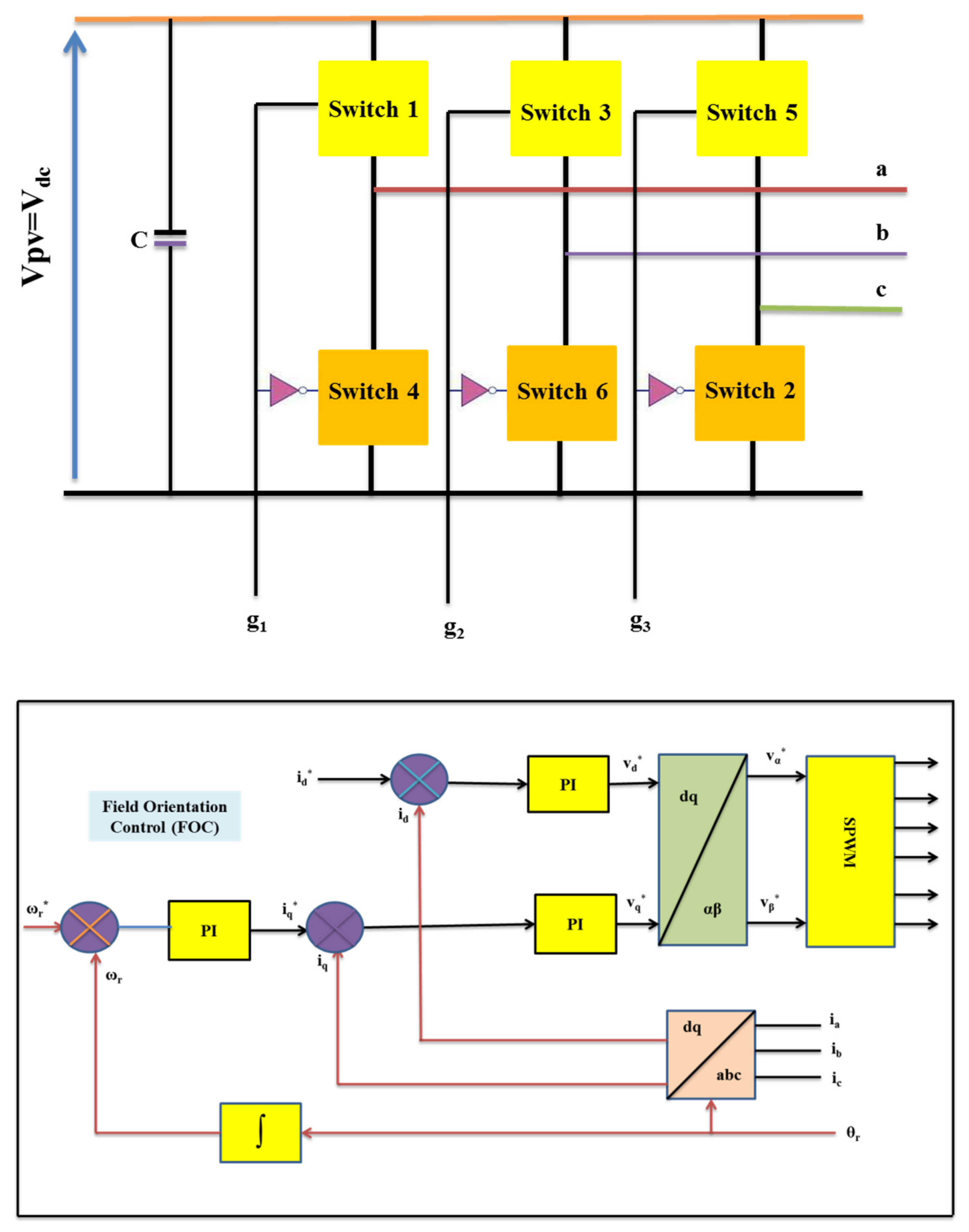
2.3. Modeling of the Three-Phase Inverter

The three-phase inverter (voltage source) was used for converting the DC voltage (Vdc) to a three-phase AC voltage (Van, Vbn and Vcn) via six IGBT switches, as shown in Figure 7a. The inverter output is represented by Equation (5) [28], and it depends on the IGBT switches status (g1, g2, and g3) if it is opened (1) or closed (0).
v a n v b n v c n = V d c 3 2 1 1 1 2 1 1 1 2 g 1 g 2 g 3

2.4. The Three-Phase SynRM Model

To avoid the inductance variation with time, the dq-axis reference frame is commonly used to model AC machines. The inductances along the dq-axis of SynRM varies with analogy current parts along the dq-axis [9,10,29,30]. The SynRM magnetic saturation results from the variation of the motor inductances It was previously proven that the SynRM model should have the effect of magnetic saturation on the motor inductances for the SynRM performance prediction in the right way [21]. Figure 5c presents the equivalent circuit of the SynRM in the dq -axis.
v d v q = R m 0 0 R m i d i q + t ω r P ω r P t λ d λ q
T e = 3 2 P λ d i q λ q i d λ d = L d i d , i q i d λ q = L q i d , i q i q T e = J t d ω r d t + B ω r + T L }
where vd denotes the voltage for the direct axis, while vq denotes the voltage for the quadrature axis; Rm represents the stator phase resistance; id represents the current along the direct axis, while iq represents the current along the quadrature axis; ωr indicates the rotor mechanical speed; P is the pole pairs number; (λ) denotes the flux linkage; J and B are the moment of inertia and viscous coefficient, respectively; and Te is the torque of the motor, while TL is the torque of the load.
Figure 5d shows the effect of magnetic saturation on the machine’s dq-axis flux-linkages as represented in Equations (6) and (7). This study obtains the effect of magnetic saturation in flux-linkages along the direct and quadrature axis from the finite element modeling method (FEM). This is accomplished via lookup tables (LUTs) for flux-linkages along the direct and quadrature axes in relation to the SynRM direct and quadrature axes’ current parts. The SynRM used in this study is a three-phase motor with 5.5 kW power, 380 V, 12.23 A, and runs at 3000 rpm. The motor stator has 36/4 slots/poles, 180/110 mm outer/inner diameter, and is fabricated from M270-50A steel type, while the motor rotor has a 35 mm/109.4 mm shaft diameter/outer diameter, 140 mm/0.3 mm stack length/air gap length, three flux barriers/pole, and is fabricated from M330-50A steel type.

2.5. Centrifugal Pump Modeling

The pump used in this study is represented on the basis of its torque–speed relation, as shown in Equation (8) as follows:
T P = C P θ 2
where T P is the pump torque, which is the same as TL in Equation (5); C P is the pump constant of proportionality; and θ 2 is the rotating speed in radian per second.

3. The Proposed Control Strategy

In the previous studies for maximizing the output power of photovoltaic–TEG, there are two MPPTs using the two DC–DC converters. In this work, only one MPPT scheme was used and it was connected to the SynRM inverter to drive the SynRM efficiently and maximize the power output of the hybrid perovskite solar cell–TEG arrays under different irradiation conditions. In this work, the control strategy was very important in enhancing the system’s performance. The control strategy determined the SynRM and the hybrid perovskite solar cell–TEG array operating point, affecting the whole system performance. The SynRM can be controlled via minimum losses, maximum efficiency, maximum power factor, and maximum torque per ampere. Here, the maximum torque per ampere technique was used to control the SynRM used in the proposed system. For maximum torque/ampere approach implementation, the field orientation control (FOC) technique (Figure 7) was used for SynRM inverter driving. Lookup tables (LUT) generated from FEM were used to achieve maximum torque per ampere strategy in FOC. The LUT correlated the direct axis current reference signal (id*) on the basis of the toque of the load. The point of the speed reference (ωr*) used in FOC was provided via the MPPT technique that controls the hybrid perovskite solar cell–TEG array. The parameters of the PI controllers were obtained via the trial-and-error attitude. For obtaining the maximum output power from the hybrid perovskite solar cell–TEG array, the MPPT technique is essential. The perturbation and observation (P&O) approach was implemented in this work. In the P&O approach, the technique’s input signals are the photovoltaic array’s measured current and voltage. The output from the P&O technique is the SynRM speed set point. The P&O approach works as follows: firstly, measure Vpv (t) and Ipv(t) at each time, then calculate Ppv(t); after this, compute ∆Ppv(t) = Ppv(t) − Ppv(t − 1) and ∆Vpv(t) = Vpv(t) − Vpv(t − 1); following these calculations, apply these rules: if ∆Ppv > 0 and ∆Vpv < 0, then ωr* = ωr + ∆ωr, and if ∆Ppv > 0 and ∆Vpv > 0, then ωr* = ωr − ∆ω; or else, if ∆Ppv < 0 and ∆Vpv < 0, then ωr* = ωr + ∆ω, and if ∆Ppv < 0 and ∆Vpv > 0, then ωr* = ωr + ∆ωr.

4. The Complete Proposed Pumping System Performance

The complete proposed and investigated system in this work is shown in Figure 8. The perovskite solar cells array and the TEG rates depend on the load requirements [31,32]. In this context, the perovskite solar cell array rate is 5.04 kW, and the TEG rate is 404.7 W. The central source for the motor feeding power is the perovskite solar cell array, sharing 93% of the load required power.
The models of the proposed system components in previous sections are used for the complete system simulation in the MATLAB environment software. In this work, two different irradiation levels were used (0.5 KW/m2 and 1 KW/m2); moreover, two studied cases were considered in this study: the first one was the SynRM fed from the perovskite solar cell array only, while the other case was the SynRM fed from the proposed hybrid perovskite solar cell array and the TEG. In the beginning, an initial motor speed setpoint was provided via the MPPT. After that, the SynRM started rotating. Then, the motor speed setpoint was increased via the MPPT, and the MPPT started to compare the perovskite solar cell array output continuously during every step with the previous one. On the basis of this, the SynRM speed increased, as presented in Figure 9, until the perovskite solar cell array’s maximum output power was reached. After that, the SynRM speed stayed at a constant value. The SynRM speed and torque with respect to time under the two studied cases are shown in Figure 9, from which it is evident that the SynRM speed successfully tracked the speed reference point in the two cases under the two different irradiation levels where SynRM speed increased when using the proposed hybrid perovskite solar cell array–TEG by about 3.9% and 2.95% under 0.5 KW/m2 to 1 KW/m2, respectively. In this context, the SynRM output torque was increased by 11% and 9.98% under 0.5 KW/m2 to 1 KW/m2, respectively, and hence the load torque of the centrifugal pump was increased by 6.75% and 5.84%, respectively. Figure 10a,b presents the perovskite solar cell array power output and the hybrid perovskite array–TEG arrays. The SynRM input power was also present under the two irradiation levels used (0.5 KW/m2 to 1 KW/m2).
The results revealed that the maximum power point of the perovskite solar cell array was achieved in the two studied cases based on the MPPT technique. Figure 10c,d reports the SynRM efficiency under the two studied cases at 0.5 KW/m2 and 1 KW/m2, respectively, where it is clear that the efficiency increased by 0.43% when using the hybrid PSC array and TEG case. Figure 11 represents direct and quadrature axis current components. From Figure 11, it is clear that the current is analogous to the two cases studied. The flow rate of the centrifugal pump is displayed in Figure 12a,b for the two studied cases under the two irradiation levels. The pump flow rate increased by 14% and 11% via using hybrid perovskite solar cells array and TEG compared to using only perovskite solar cells array under 0.5 KW/m2 to 1 KW/m2, respectively. The SynRM losses in the two cases at two different irradiation levels are presented in Figure 12c,d. On the basis of the obtained results, the proposed control strategy succeeded in tracking the PSC array’s maximum power point and deriving the motor at maximum torque per ampere state. In this context, the proposed hybrid perovskite solar cell–TEG array fed the motor via an inverter without DC–DC converters or batteries. Accordingly, the short life problems and the high replacement cost were avoided. The results exposed the fact that the motor’s output power and the pump’s flow rate were improved by 11% and 14%, respectively, due to using the high-power-density hybrid perovskite solar cell–TEG array, in comparison with using only the perovskite solar cell array.

5. Economic Analysis

The PSCs used in this study were fabricated and characterized in the lab, as described in Section 2 of this paper. The fabricated device (one cell) had a current density of 24.3 mA/cm2, open-circuit voltage of 1.072 V, current density at a maximum power of 21.4 mA/cm2, voltage at a maximum power of 0.91 V, fill factor of 0.74, transformation efficiency of 19.3%, active area as 0.1 cm2, and maximum power of 19.5 mW. For feeding the SynRM used in this study (details in the SynRM model part), a perovskite solar cell array with 3.12 m2 as an active area based on the lab fabricated solar cell was used, while for the same application under the same rating and conditions, the silicon-based array (KD135SX-UPU) area was 36 m2 and the TEG used in both cases was TE-MOD-1W2V-40S, which had 0.0016 m2 as the active area. This means the area needed for panel installations was very small in the case of perovskite-based devices (only 3.12 m2) compared to silicon-based devices (36 m2) for the same application. The perovskite solar cells were easily fabricated at low temperatures; in contrast, silicon solar cells needed high temperatures for fabrication.

6. Experimental Confirmation

For the proposed system simulation results validation, a test bench was constructed for the lab for this purpose, as shown in Figure 13a. As it appeared in Figure 13a, the system components were (1) three-phase SynRM fed on a SEMIKRON inverter as described previously in this work; (2) a coupling unit; (3) a three-phase induction powered from the commercial inverter; (4) a power analyzer for power, current, and voltage measurements; (5) a DSpace 1103 control board; (6) a SEMIKRON inverter; (7) a programmable DC source; (8) a commercial inverter; and (9) multimeters for voltage and current measurements.
The centrifugal pump load was emulated via the three-phase induction motor and the hybrid perovskite solar cell array, and TEG was emulated via the programmable DC source.
The hybrid perovskite solar cell array–TEG at an irradiation level of 1000 W/m2 case results were validated in the test bench constructed in the lab. Figure 13b,c presents the SynRM current components, while Figure 13d,e reports the measured and the set point of the SynRM speed. The results demonstrated that the SynRM accurately followed the set point values. The SynRM measured efficiency map is presented in Figure 13f. The SynRM and the load torques are reported in Figure 13g. Figure 13g shows that both measured and simulated torque values were in harmony.

7. Conclusions

In this work, for the first time, a hybrid perovskite solar cell–thermoelectric generator (TEG) array for feeding the SynRM used in the water pumping system was recommended and investigated. Moreover, a proposed control strategy in this work was presented and investigated for system driving suitably via the SynRM inverter controlling. The proposed system had no batteries or DC–DC converters, leading to low cost and system complexity reduction. Moreover, the TEG installed at the backside of the PSCs used the generated heat to produce electricity instead of cooling the cells via a cooling system. The result revealed that SynRM output power increased by 11%, while the pump’s flow rate increased by 14% when feeding the SynRM from hybrid perovskite solar cell–TEG arrays compared to feeding the SynRM from the perovskite solar cell array only. Furthermore, the area needed for panel installations was minimal in the case of perovskite-based devices (only 3.12 m2) compared to silicon-based devices (36 m2) for the same application, leading to land and cost saving. Ultimately, the whole proposed system’s cost and performance were enhanced. The test bench was constructed in the lab, and experimental measurements were taken to validate the simulation results. The entirety of the results showed the efficiency of using the proposed hybrid perovskite solar cell–TEG arrays for SynRM driving and use in water pumping applications.

Author Contributions

Conceptualization, A.A.Z.; Data curation, A.A.Z.; Formal analysis, A.A.Z. and M.N.I.; Funding acquisition, A.A.Z. and I.B.M.T.; Investigation, A.A.Z.; Methodology, A.A.Z.; Project administration, A.A.Z.; Resources, A.A.Z.; Software, A.A.Z. and M.N.I.; Supervision, B.Y., P.S., E.H. and P.F.; Validation, A.A.Z.; Visualization, A.A.Z. and M.N.I.; Writing—original draft, A.A.Z.; Writing—review & editing, A.A.Z., I.B.M.T. and B.Y. All authors have read and agreed to the published version of the manuscript.

Funding

This research was funded by [Taif University Researchers Supporting Project] grant number [TURSP-2020/61], [Egyptian Ministry of Higher Education Cultural Affairs and Missions Sector], [Operational Program Competitiveness, Entrepreneurship and Innovation, under the call RESEARCH-CREATE-INNOVATE] grant number [T1EDK-03547, MIS 5033808] And The APC was funded by [Taif University Researchers Supporting Project].

Institutional Review Board Statement

Not applicable.

Informed Consent Statement

Not applicable.

Data Availability Statement

All data are contained within the article.

Acknowledgments

The authors would like to acknowledge the financial support received from Taif University Researchers Supporting Project Number (TURSP-2020/61), Taif University, Taif, Saudi Arabia. Moreover, Alaa A. Zaky acknowledges the funding of his postdoctoral research by the Egyptian Ministry of Higher Education (Cultural Affairs and Missions Sector). P. Falaras acknowledges financial support by the European Regional Development Fund of the European Union and Greek national funds through the Operational Program Competitiveness, Entrepreneurship and Innovation, under the call RESEARCH-CREATE-INNOVATE (project code: T1EDK-03547, MIS 5033808).

Conflicts of Interest

The authors declare that there are no conflict of interest.

References

  1. Verma, V.; Kane, A.; Singh, B. Complementary performance enhancement of PV energy system through thermoelectric generation. Renew. Sustain. Energy Rev. 2016, 58, 1017–1026. [Google Scholar] [CrossRef]
  2. Tyagi, V.V.; Rahim, N.A.A.; Rahim, N.A.; Selvaraj, J.A.L. Progress in solar PV technology: Research and achievement. Renew. Sustain. Energy Rev. 2013, 20, 443–461. [Google Scholar] [CrossRef]
  3. Parida, B.; Iniyan, S.; Goic, R. A review of solar photovoltaic technologies. Renew. Sustain. Energy Rev. 2011, 15, 1625–1636. [Google Scholar] [CrossRef]
  4. Attivissimo, F.; di Nisio, A.; Lanzolla, A.M.L.; Paul, M. Feasibility of a photovoltaic–thermoelectric generator: Performance analysis and simulation results. IEEE Trans. Instrum. Meas. 2015, 64, 1158–1169. [Google Scholar] [CrossRef] [Green Version]
  5. Babu, C.; Ponnambalam, P. The theoretical performance evaluation of hybrid PV TEG system. Energy Convers. Manag. 2018, 173, 450–460. [Google Scholar] [CrossRef]
  6. Hasanuzzaman, M.; Malek, A.B.M.A.; Islam, M.M.; Pandey, A.K.; Rahim, N.A. Global advancement of cooling technologies for PV systems: A review. Sol. Energy 2016, 137, 25–45. [Google Scholar] [CrossRef]
  7. Lin, J.; Liao, T.; Lin, B. Performance analysis and load matching of a photovoltaic–thermoelectric hybrid system. Energy Convers. Manag. 2015, 105, 891–899. [Google Scholar] [CrossRef]
  8. Benlarbi, K.; Mokrani, L.; Nait-Said, M.S. A fuzzy global efficiency optimization of a photovoltaic water pumping system. Sol. Energy 2004, 77, 203–216. [Google Scholar] [CrossRef]
  9. Nabil, M.; Allam, S.M.; Rashad, E.M. Modeling and design considerations of a photovoltaic energy source feeding a synchronous reluctance motor suitable for pumping systems. Ain Shams Eng. J. 2012, 3, 375–382. [Google Scholar] [CrossRef] [Green Version]
  10. Nabil, M.; Allam, S.M.; Rashad, E.M. Performance improvement of a photovoltaic pumping system using a synchronous reluctance motor. Electr. Power Compon. Syst. 2013, 41, 447–464. [Google Scholar] [CrossRef]
  11. Solar Cells Efficiency Map. Available online: https://www.nrel.gov/pv/cell-efficiency.html (accessed on 27 June 2022).
  12. Balis, N.; Zaky, A.A.; Perganti, D.; Kaltzoglou, A.; Sygellou, L.; Katsaros, F.; Stergiopoulos, T.; Kontos, A.G.; Falaras, P. Dye Sensitization of Titania Compact Layer for Efficient and Stable Perovskite Solar Cells. ACS Appl. Energy Mater. 2018, 1, 6161–6171. [Google Scholar] [CrossRef]
  13. Gkini, K.; Verykios, A.; Balis, N.; Kaltzoglou, A.; Papadakis, M.; Adamis, K.S.; Armadorou, K.-K.; Soultati, A.; Drivas, C.; Gardelis, S.; et al. Enhanced Organic and Perovskite Solar Cell Performance through Modification of the Electron-Selective Contact with a Bodipy−Porphyrin Dyad. ACS Appl. Mater. Interfaces 2020, 12, 1120–1131. [Google Scholar] [CrossRef]
  14. Gkini, K.; Balis, N.; Papadakis, M.; Verykios, A.; Skoulikidou, M.; Drivas, C.; Kennou, S.; Golomb, M.; Walsh, A.; Coutsolelos, A.G.; et al. Manganese porphyrin interface engineering in perovskite solar cells. ACS Appl. Energy Mater. 2020, 3, 7353–7363. [Google Scholar] [CrossRef]
  15. Zaky, A.A.; Christopoulos, E.; Gkini, K.; Arfanis, M.K.; Sygellou, L.; Kaltzoglou, A.; Stergiou, A.; Tagmatarchis, N.; Balis, N.; Falaras, P. Enhancing efficiency and decreasing photocatalytic degradation of perovskite solar cells using a hydrophobic copper-modified titania electron transport layer. Appl. Catal. B Environ. 2021, 284, 119714. [Google Scholar] [CrossRef]
  16. Zaky, A.A.; Ibrahim, M.N.; Rezk, H.; Christopoulos, E.; El Sehiemy, R.A.; Hristophorou, E.; Kladas, A.; Sergeant, P.; Falaras, P. Energy Efficiency Improvement of Water Pumping System Using Synchronous Reluctance Motor Fed by Perovskite Solar Cells. Int. J. Energy Res. 2020, 44, 11629–11642. [Google Scholar] [CrossRef]
  17. Zaky, A.A.; Balis, N.; Gkini, K.; Athanasekou, C.; Kaltzoglou, A.; Stergiopoulos, T.; Falaras, P. Dye Engineered Perovskite Solar Cells under Accelerated Thermal Stress and Prolonged Light Exposure. ChemistrySelect 2020, 5, 4454–4462. [Google Scholar] [CrossRef]
  18. Zaky, A.A.; El Sehiemy, R.A.; Rashwan, Y.I.; El Hossieni, M.A.; Gkini, K.; Kladas, A.; Falaras, P. Optimal Performance Emulation of PSCs using the Elephant Herd Algorithm Associated with Experimental Validation, Electronic and Photonic Devices and Systems section. ECS J. Solid State Sci. Technol. 2019, 8, Q249–Q255. [Google Scholar] [CrossRef]
  19. Balis, N.; Zaky, A.A.; Athanasekou, C.; Silva, A.M.T.; Sakellis, E.; Vasilopoulou, M.; Stergiopoulos, T.; Kontos, A.G.; Falaras, P. Investigating the Role of Reduced Graphene Oxide as a Universal Additive in Planar Perovskite Solar Cells. J. Photochem. Photobiol. A Chem. 2020, 386, 112141. [Google Scholar] [CrossRef]
  20. Zaky, A.A.; Fathy, A.; Rezk, H.; Gkini, K.; Falaras, P.; Abaza, A. A Modified Triple-Diode Model Parameters Identification for Perovskite Solar Cells via Nature-Inspired Search Optimization Algorithms. Sustainability 2021, 13, 12969. [Google Scholar] [CrossRef]
  21. Ibrahim, M.N.; Sergeant, P.; Rashad, E.M. Relevance of including saturation and position dependence in the inductances for accurate dynamic modeling and control of SynRMs. IEEE Trans. Ind. Appl. 2017, 53, 151–160. [Google Scholar] [CrossRef] [Green Version]
  22. Ibrahim, M.N.F.; Abdel-khalik, A.S.; Rashad, E.M.; Sergeant, P. An improved torque density synchronous reluctance machine with a combined star–delta winding layout. IEEE Trans. Energy Convers. 2018, 33, 1015–1024. [Google Scholar] [CrossRef]
  23. Available online: https://www.nextbigfuture.com/2019/02/first-commercial-perovskite-solar-late-in-2019-and-the-road-to-moving-the-energy-needle.html (accessed on 27 June 2022).
  24. Song, Z.; McElvany, C.L.; Phillips, A.B.; Celik, I.; Krantz, P.W.; Watthage, S.C.; Liyanage, G.K.; Apul, D.; Heben, M.J. A technoeconomic analysis of perovskite solar module manufacturing with low-cost materials and techniques. Energy Environ. Sci. 2017, 10, 1297–1305. [Google Scholar] [CrossRef]
  25. Available online: https://gotecotech.com/a-new-solar-cell-material-could-make-solar-power-dirtcheap/#:~:text=Perovskites%20offer%20a%20great%20combination%20of%20cheaper%20production,20%20cents%20per%20watt%2C%20that%20is%2086%25%20cheaper (accessed on 27 June 2022).
  26. Ouyang, Z.; Li, D. Design of segmented high-performance thermoelectric generators with cost in consideration. Appl. Energy 2018, 221, 112–121. [Google Scholar] [CrossRef] [Green Version]
  27. Available online: https://www.tegmart.com/datasheets/TGPR-10W4V-40S.pdf (accessed on 27 June 2022).
  28. Lyden, S.; Haque, M.E. Maximum Power Point Tracking techniques for photovoltaic systems: A comprehensive review and comparative analysis. Renew. Sustain. Energy Rev. 2015, 52, 1504–1518. [Google Scholar] [CrossRef]
  29. Heidari, H.; Rassõlkin, A.; Kallaste, A.; Vaimann, T.; Andriushchenko, E.; Belahcen, A.; Lukichev, D.V. A Review of Synchronous Reluctance Motor Drive Advancements. Sustainability 2021, 13, 729. [Google Scholar] [CrossRef]
  30. Ibrahim, M.N.; Rezk, H.; Al-Dhaifallah, M.; Sergeant, P. Modelling and Design Methodology of an Improved Performance Photovoltaic Pumping System Employing Ferrite Magnet Synchronous Reluctance Motors. Mathematics 2020, 8, 1429. [Google Scholar] [CrossRef]
  31. Ibrahim, M.N.; Sergeant, P.; Rashad, E.M. Design of low cost and efficient photovoltaic pumping system utilizing synchronous reluctance motor. In Proceedings of the International Electric Machines and Drives Conference (IEMDC), Miami, FL, USA, 21–24 May 2017. [Google Scholar]
  32. Ibrahim, M.N.; Rezk, H.; Al-Dhaifallah, M.; Sergeant, P. Solar array fed synchronous reluctance motor driven water pump: An improved performance under partial shading conditions. IEEE Access 2019, 7, 77100–77115. [Google Scholar] [CrossRef]
Figure 1. (a) The conventional photovoltaic water pumping system. (b) The proposed system schematic diagram. (c) The flow chart of the proposed methodology.
Mathematics 10 02417 g001aMathematics 10 02417 g001b
Figure 2. (a) Perovskite solar cell complete lab fabricated device. (b) The device schematic architecture. (c) The XRD for the perovskite layer. (d) Device energy level diagram.
Mathematics 10 02417 g002
Figure 3. (a) The device J-V curves (reverse and forward scans). (b) Perovskite deposited upon TiO2 layer absorbance spectra. (c) The complete device impedance.
Mathematics 10 02417 g003
Figure 4. The perovskite solar cell J-V curves measuring system.
Mathematics 10 02417 g004
Figure 5. (a) The perovskite solar cell single diode model. (b) The TEG equivalent model. (c) The dq axis equivalent circuit of SynRM. (d) SynRM flux-linkages along the dq-axis as a relation in dq-axis current parts.
Mathematics 10 02417 g005
Figure 6. (a) The perovskite solar cell array relationships between current and voltage as irradiation levels change. (b) The perovskite solar cell array relationships between power and voltage as irradiation levels change. (c) The TEG (TE-MOD-1W2V-40S) power–voltage curve. (d) The TEG (TE-MOD-1W2V-40S) current–voltage curves.
Mathematics 10 02417 g006
Figure 7. The three-phase voltage source inverter equivalent circuit diagram (top). The field orientation control strategy schematic diagram (bottom).
Mathematics 10 02417 g007
Figure 8. The complete proposed system schematic diagram.
Mathematics 10 02417 g008
Figure 9. The SynRM speed versus time under 0.5 KW/m2 to 1 KW/m2 (a,b). The SynRM torque versus time under 0.5 KW/m2 to 1 KW/m2 (c,d).
Mathematics 10 02417 g009
Figure 10. The power as a function of time at two irradiation levels (a,b). The motor efficiency versus time (c,d).
Mathematics 10 02417 g010
Figure 11. The SynRM current components with time where (a,b) are the direct axes currents and (c,d) are the quadrature axes currents.
Mathematics 10 02417 g011
Figure 12. The flow rate of the pump (a,b) and the SynRM losses with time (c,d).
Mathematics 10 02417 g012
Figure 13. Experimental test bench (a). dq-axis current components (b,c). (d) SynRM measured speed versus time. (e) Power of the SynRM and pump at rated condition. (f) Efficiency map of the whole drive system. (g) The measured SynRM and reference load torques as a function of time.
Mathematics 10 02417 g013
Publisher’s Note: MDPI stays neutral with regard to jurisdictional claims in published maps and institutional affiliations.

