Article

MHD Micropolar Fluid in a Porous Channel Provoked by Viscous Dissipation and Non-Linear Thermal Radiation: An Analytical Approach

1
Department of Mathematics, College of Engineering and Technology, SRM Institute of Science and Technology, Kattankulathur 603203, Tamil Nadu, India
2
Division of Mathematics, School of Advanced Sciences, Vellore Institute of Technology, Chennai Campus, Chennai 600127, Tamil Nadu, India
*
Authors to whom correspondence should be addressed.
Mathematics 2023, 11(1), 183; https://doi.org/10.3390/math11010183
Submission received: 23 November 2022 / Revised: 12 December 2022 / Accepted: 20 December 2022 / Published: 29 December 2022
(This article belongs to the Topic Computational Fluid Dynamics (CFD) and Its Applications)

Abstract

:
The present exploration discusses the combined effect of non-linear thermal radiation along with viscous dissipation and magnetic field through a porous medium. A distinctive aspect of our work is the simultaneous use of porous wall and a porous material. The impact of thermal rays is essential in space technology and high temperature processes. At the point when the temperature variation is very high, the linear thermal radiation causes a noticeable error. To overcome such errors, nonlinear thermal radiation is taken into account. The coupled system of ordinary differential equations are derived from the partial differential equation. The dimensional model equations are transformed into non-dimensional forms using some appropriate non-dimensional transformation and the resulting nonlinear equations are solved numerically by executing persuasive numerical technique R-K integration procedure with the shooting method. Graphical analysis were used to assess the consequences of engineering factors for the momentum, angular velocity, concentration and temperature profiles. The skin friction values, local Sherwood and Nusselt number are the fascinating physical quantities whose numerical data are computed and validated against different parametric values. The vortex viscosity parameter and spin gradient viscosity parameter shows the reverse phenomenon on micro-rotation profile. The thermal radiation phenomena flattens the temperature and speeds up the heat transfer rate in the lower wall and a peak in the concentration is observed for the P e m > > 1 due to the inertial force. The Variational Iteration Method (VIM) and Adomian Decomposition Method (ADM) are the two analytical approach which have been incorporated here to decipher the non linear equations for showing better approximity. Comparisons with existing studies are scrutinized very closely and they are determined to be in good accord.

1. Introduction

Non-Newtonian fluids have extensive applications in industry and engineering sectors. No single relation exists that entirely describes the features of non-Newtonian fluids. Applications depicting the characteristics of non-Newtonian fluids include foams, apple sauce, sugar solution, soaps, clay, and lubricants, etc. Numerous non-Newtonian liquid models are defined by the researchers. Among these, micropolar fluids are category of fluids that include co-polymerized molecules with irregular structures which moves in a viscous medium. Gyratory micro-sized particles in these fluids create new subtleties in contemporary high-tech engineering mechanics and ergonomics. Some typical examples of micropolar fluids include the extraction of crude oil, sludge and blood flows, polymeric materials, liquid precipitation and fluids with bar-like components. In contrast to classical fluids, which only display translational momentum, micropolar fluids exhibit both rotational and translational momentum concurrently. Eringen [1] was the first person who rooted out that the Navier-Stokes premises, do not effectively describe the aspects of many physiological fluids, which display microscopic influences resulting from the local structure and micro motions of the fluid constituents. One form of fluid that fits within this class is micropolar fluid. Later, Eringen [2] expanded his initial ideas to include thermo-micropolar fluids and created constitutive laws. Applications for this type of transport phenomenon study includes the aerodynamic extruded plastics, blow molding, rolling and extrusion in manufacturing processes as well as water phase during condensation processing. By using Eringen’s theory, Lukaszewicz [3] investigated the mathematical characteristics of the micropolar fluid flow idea and identified the non-Newtonian nature of these fluids. In addition, the theoretical simulations for describing how microorganisms move through blood while being heated which was scrutinized by Rana et al. [4] and he examined the effects of velocity gradient on the micro-organisms floating in blood by treating blood as a Williamson fluid.
The research community has been interested in channel flows owing to their uses in the disciplines of binary gas diffusion, micro-fluidic devices, surface cremation, temperature control, flocculation, granular regression and designing of air to circulate in the nasal passages. Since micropolar fluid is a trendy topic of the study many researchers have looked into the flow and heat transmission problem connected with it. Due to its widespread use in numerous fluid fluxes, the flow of micropolar fluid via soddened porous media has drawn tremendous attention. Convection flow liable to porous channel act as a component in environmental and industrial circuits including geothermal energy systems and heat exchanges devices. Heat transport analysis on porous surfaces is extremely practical due to its many uses. On the other hand, flow of porous media has is important application in heat removal from nuclear fuel, debris, underground disposal of radioactive waste material, micro-emulsions, geotechnical hydrodynamics and paper production, etc. Rocks, dunes in seashore, respiratory track, granite, the bile duct and alimentary canal with stones in blood capillaries are the typical examples of natural porous materials.
Owing to their tremendous uses in areas including MHD generating electricity, blood plasma, mettaloids, paper manufacture, micro-floppy and fractional distillation porous media play a vital part in the fluid transportation of many bio-mechanics research. Later Tetbirt et al. [5] studied the effect of micropolar fluid subject to the vertical channel in the conducting fields. Pal and Biswas [6] investigated the MHD flow on a chemically reactive micropolar fluid in a porous medium. Nisar et al. [7] explores the heat and mass transportation of MHD micropolar fluid in a porous annulus and they concluded that The material parameters promotes the growth of micro-rotation profile but the magnetized particles shows the varying effects. In view of that, Ashraf et al. [8] examined the movement of micropolar fluids via a porous tube and they considered different permeability in channel annulus. By using a porous shrinkage layer, Turkyilmazoglu [9] looked into the details of energy transfer in micropolar fluid flow. Cao et al. [10] discussed the analysis of micropolar fluid using a porous improved conduits. In a small-width permeable channel, Lu et al. [11] focused on the two-dimensional flow of a micropolar fluid. Numerous scholars can examine the pressure distribution of blood circulation in glomerular of the kidneys using the data that they established. By adopting FEM, Shamshuddin and Thumma [11] were able to compute a theoretical formulation of MHD diffusive flow in micropolar fluid past a porous media and discovered that high values of the micro-rotation component reduces the angular velocity profile. Tiwari et al. [12] conducted an empirical evaluation by employing heat transfer approach to assess the flow of micro polar fluid across a porous multilayered microvessels. Micropolar fluid flow over a linear stretching surface with magnetic field was analytically studied by Siddheshwar and Mahabaleshwar [13].
The cumulative impact of mass and energy transport in streams have a variety of applications in earth sciences and technological field including energy absorption, geological underground aquifers, drying, evaporation at the surface of a water body, synthesized substances, refrigeration in atomic furnace, drying of absorbents, pollution investigations, porcelain fabrication, solvent extraction, fiber insulating material, latent heat vaporization. Over the past few decades, there has been a lot of research conducted on the issues of combined effects of mass and heat transports. The significance of thermal radiation in heat transmission has huge applications in a wide range of thermal engineering fields, including industrial operations that use hybrid solar and electric power systems, aircraft, nuclear power plants, rocket motors, missiles and satellite communications. Most probably, thermal radiation happens as a result of significant temperature difference between the two media. For investigations with greater temperature variations, it is not suitable to take linear thermal radiation into account. Therefore, in contrast to linear thermal radiation, the researchers recently suggested the idea of nonlinear thermal radiation with the inclusion of some parameters. This additional parameter exhibits the difference between surface temperature and uniform temperature [14]. Viscous dissipation alters temperature distributions and impacts heat transfer rates by acting as an energy source. Depending on whether the sheet is being heated or cooled, viscous dissipation works differently.
Hayat et al. [15] studied the effects of nonlinear thermal radiation on the three-dimensional nanofluid flow past a stretching sheet. Animasaun et al. [16] analyzed the effects of nonlinear thermal radiation and induced magnetic field on viscoelastic fluid flow toward a stagnation point. From this study, they concluded that the nonlinear thermal radiation improves the temperature profiles and suppresses the rate of heat transfer. Radiative magneto hydrodynamic nanofluid flow due to gyrotactic microorganisms with chemical reactions and non-linear thermal radiation is explored by Ramzan et al. [17]. Brownian movement and thermophoresis behaviors in radiative flow of micropolar nanoliquids with Lorentz force is demonstrated by Patel and Singh [18].
By exploiting the contribution of viscous dissipation, Xinhui Si et al. [19] were able to tackle the micropolar fluid problem with dilating or shrinking walls in a absorbent conduits. In contrast, the MHD micropolar fluid in a vertical permeable channel with scattering of viscous phenomenon was explored by Muthuraj et al. [20]. Sheri and Shamshuddin [21] study the MHD flow of a micropolar liquid across a stretched surface with chemical reaction and viscous dissipation. In order to account for viscous dissipation, Ahmad et al. [22] numerically investigated the heat and mass transfer flow of an incompressible micropolar fluid through a resistive porous material between channel walls. They explored a clear view for the cause of viscous dissipation affects the rate of heat and mass transfer at the channel’s lower and upper walls as well as how a rise in the Eckert number and the Peclet number for heat diffusion affects the rate of heat transfer at both sides of a wall. Algehyne et al. [23] have deliberated the influence of viscous dissipation and nonlinear thermal radiations upon micropolar MHD fluid flow and have established that fluid flow has decayed with growth in magnetic parameter while thermal characteristics have enlarged with upsurge in electric, magnetic, thermal ratio and radiation factors. Many articles that explore the significance of non linear thermal radiation with viscous dissipation effects are in [24,25].
In the absence of sufficient experimental data for micropolar fluids, the goal of this work is to investigate the impact of the engineering parameters of the micropolar fluid flow in a permeable channel by means of theoretical study. The preponderance of engineering issues, particularly some heat transfer equations are non-linear. As a result, some of them are resolved numerically and others analytically. In this analysis, we investigated the micropolar fluids with a porous annulus analytically by Variational Iteration Method (VIM) and Adomian Decomposition Method (ADM).
The variational iteration method (VIM) is a new approach for finding the approximate solution of linear and nonlinear problems. This method was considered interesting due to its simplicity, high accuracy and efficiency in finding analytical solutions. The Lagrange multipliers, which can be ideally found by variational theory that can be used to create correction function and from the possible unknown the initial approximations, can be selected are the main novelty of this method. The predictions that this technique generates are accurate for both very large and small parameters [26,27,28]. Moreover, Adomian decomposition method is one of the semi-exact methods that does not require linearization or discretization, and various modifications has strengthened its efficacy. This method has the benefit of being able to approximate a solution to large class of nonlinear equations without the use of linearization, perturbation, closure approximation, or discretization techniques. As a result, its predictions are more accurate. Many scientists have chosen to employ this technique to address fluid dynamic topics because of ADM advantages [29,30,31].
A review and analysis of litrature has revealed that a numerical study on MHD micropolar fluid past a porous material in a permeable channel with the extra effects of non-linear thermal radiation, viscous dissipation and magnetic field has not been analytically evaluated by VIM and ADM. By applying the similarity transformations to the governed partial differential equations, the corresponding non-dimensional ordinary differential equations are obtained and then tackled numerically by MATLAB-bvp4c with the aid of shooting technique. The consequence of various factors includes velocity, angular momentum, temperature, concentration are portrayed graphically and discussed convincingly. Further, tables were incorporated in order to understand the consequences of different parameters on skin friction coefficients, Sherwood and Nusselt numbers. Additionally, the equation are solved analytically by Adomian decomposition method and variational iteration method for showing better approximations. The analytical results and the numerical results are compared for the non dimensionless parameter f ( η ) and θ ( η ) and also the numerical results are compared with previously published articles. Both numerical and analytical results comparison are found to be in remarkable agreement.
The following are the research questions to enrich the novelty of the study:
  • How do the porosity parameter and magnetic number affect the velocity profile?
  • How do the vortex viscosity parameter and magnetic parameter affects the angular velocity profile.
  • Why non-linear thermal radiation is chosen to analyze the heat transfer process?
  • In what way the radiation term and temperature ratio parameter affects the temperature profile?
  • How does the Peclet number for heat and mass transfer affect the temperature and concentration profile?
  • What is the superiority of ADM and VIM compared with other analytical method?

2. Problem Formulation

We perceive the steady state laminar flow of a micropolar fluid in a two-dimensional tube through a resistive porous medium between a channel, where fluid is uniformly added or vented at velocity v 0 . The thermal radiation and effects of viscous dissipation are incorporated in the energy equation. The parapet of the channel have the co-ordinates y = ± h and adjacent to the x axis where the channel width is indicated as 2h. T 1 , C 1 , and T 2 , C 2 are the temperature and concentration for the lower and upper wall accordingly. In geometrical concept, the Cartesian coordinate system is chosen in such way that the x-axis is measured along the direction of the plate, y-axis is normal to the plate and z-axis is considered to be zero. The physical geometry with its co-ordinate system is shown in Figure 1.
For the flow assumptions listed above, the appropriate governing differential equation has the form:
u x + v y = 0
u u x + v u y = 1 ρ p x + μ + κ ρ 2 u x 2 + 2 u y 2 + κ ρ N y μ + κ ρ k * u σ * B 0 2 ρ u
u v x + v v y = 1 ρ p y + μ + k ρ 2 v x 2 + 2 v y 2 κ ρ N x μ + κ ρ k * v σ * B 0 2 ρ v
u N x + v N y = k ρ j 2 N + u y v x + μ s ρ j 2 N x 2 + 2 N y 2
u T x + v T y = k ρ c p 2 T y 2 1 ρ c p q r * y + σ * B 0 2 u 2 ρ c p + μ + κ ρ c p u y 2
u C x + v C y = D 2 C y 2
where (u,v,0) are the velocity components for (x,y,z) axes, respectively, and ρ , c p , k, k * , N, P, D, T, C, j, q r and k are the fluid density, specific heat at constant pressure, vortex viscosity, Darcy permeability, molecular diffusivity, micro-rotation or angular velocity, fluid pressure, temperature, species concentration, micro inertia density, radiative heat flux and thermal conductivity, respectively.
Due to fundamental distinctions between radiation and convection-conduction energy exchange systems, the thermal radiation phenomena has critical significance at high absolute temperatures. Some equipment is made to function at high temperatures in space missions for achieving high thermal efficacy. Because of this, when assessing thermal effects with high temperatures, radiation effects play a crucial role. In accordance with non-linear radiation the Rosseland’s approximation the heat flux radiation q r * is given by,
q r * = 4 σ 3 k 0 T 4 y
Here, σ is Stefan’s Boltzmann constant and k 0 is the absorption coefficient. The similarity variable related to the Energy equation is T = T 2 [ 1 + ( θ w 1 ) θ ] with the temperature ratio parameter θ w = T 1 T 2 . Now, Equation (5) reduces to
u T x + v T y = k ρ c p 2 T y 2 + 4 σ 3 k 0 ρ c p 4 T 3 2 T y 2 + σ * B 0 2 u 2 ρ c p + μ + κ ρ c p u y 2
The imposed boundary constraints according to the flow are,
u = 0 , v = v 0 , N = s u y , T = T 1 , C = C 1 , a t y = h u = 0 , v = + v 0 , N = v 0 x h 2 , T = T 2 , C = C 2 , a t y = + h
In these boundary assumptions, S is referred to as a boundary parameter, and v 0 > 0 describes the suction velocity, while v 0 < 0 mentions the injection velocity. The condition v = ± v 0 shows that the fluid is being sucked (injected) uniformly through the channel walls, whereas u = 0 represents the no slip condition due to stationary walls. Moreover, N indicates micro-rotation of the fluid at the walls. The case s = 0 represents concentrated particle flows in which micro elements close to the wall are unable to rotate. Other interesting particular cases that have been considered in the literature include s = 0.5 which represents weak concentrations and the vanishing of the antisymmetric part of the stress tensor and s = 1 which represents turbulent flow.

3. Dimensionless Formulation

Dimensionless variables are highlighted as follows for non-dimensionalize the provided governed equations:
η = y h , ψ = v 0 x f ( η ) , N = g ( η ) v 0 x h 2 , θ ( η ) = T T 2 T 1 T 2 , ϕ ( η ) = C C 2 C 1 C 2 ,
By using these similarity variables, the Equations (1)–(6) are changed into a set of ordinary differential equations.
1 + N 1 f N 1 g R e ( f f f f ) P 0 ( 1 + N 1 ) f H a f = 0
N 1 ( f 2 g ) + N 2 g N 3 R e ( f g f g ) = 0
1 + 1 R ( 1 + ( θ w 1 ) θ ) 3 θ + 3 R ( θ w 1 ) ( 1 + ( θ w 1 ) θ ) 2 θ 2 + P e h ( f θ f θ ) + P r H a E c f 2 + P r E c ( 1 + N 1 ) f 2 = 0
ϕ + P e m f ϕ f ϕ = 0
In perspective of Equation (10), the boundary conditions are transformed as follows,
f = 0 , f = 1 , g = 0 , θ = 1 , ϕ = 1 a t η = 1 f = 0 , f = 1 , g = 1 , θ = 0 , ϕ = 0 a t η = + 1
where,
N 1 = κ μ , N 2 = ν s μ h 2 , N 3 = j h 2 , R e = v 0 ν h , P 0 = h 2 k * H a = h 2 σ * B 0 2 μ , S c = ν D , G r = g β r A h 4 ν 2 , P e h = P r R e , θ w = T 1 T 2 P e m = S c R e , N r = 3 k 0 k 16 σ T 3 , P r = ν ρ c p k , E c = v 0 2 c p ( θ w 1 )
Here, N 1 , N 2 and N 3 are the vortex viscosity, spin gradient viscosity and micro-inertia density, respectively, R e is the Reynolds number, P 0 is the porosity parameter, Magnetic parameter is denoted as H a , P r is the Prandtl number, S c is the Schmidt number, P e h and P e m are the Peclet number for heat and mass transfer, Eckert number is denoted as E c , R n is the Radiation parameter.

4. Numerical Approach

The Runge–Kutta–Fehlberg integration methodology has been executed here to decipher the set of ordinary differential Equations (11)–(14) with boundary constraint Equation (15) numerically. The R-K method along with shooting process is enacted here which is composed of a number of repeating procedures for deriving the solutions. The boundary constraints and the guided equations are merged together to create a series of first order derivatives,
( f , f , f , f , g , g , θ , θ , ϕ , ϕ ) = ( f 1 , f 2 , f 3 , f 4 , f 5 , f 6 , f 7 , f 8 , f 9 , f 10 )
In terms of Equation (17), Equations (11)–(14) takes the following form,
f 4 = N 1 N 2 N 1 ( f 3 2 f 5 ) + N 3 R e ( f 1 f 6 f 2 f 5 ) + R e ( f 1 f 4 f 2 f 3 ) + P 0 ( 1 + N 1 ) f 3 + H a f 3 1 + N 1
f 6 = N 1 ( f 3 2 f 5 ) + N 3 R e ( f 1 f 6 f 2 f 5 ) N 2
f 8 = ( 3 N r ( θ w 1 ) ( 1 + ( θ w 1 ) f 7 ) 2 ) f 8 2 P e h ( f 2 f 7 f 1 f 8 ) P r H a E c f 2 2 P r E c ( 1 + N 1 ) y 3 2 ( 1 + 1 N r ( 1 + ( θ w 1 ) f 7 ) 3 ) f 10 = P e m f 2 f 9 + P e m f 1 f 10
The boundary condition Equation (15) becomes,
f 1 = 1 , f 2 = 0 , f 5 = 0 , f 7 = 1 , f 9 = 1 a t η = 1 f 1 = 1 , f 2 = 0 , f 5 = 1 , f 7 = 0 , f 9 = 0 a t η = + 1
Since f 3 ( 0 ) , f 4 ( 0 ) , f 6 ( 0 ) , f 8 ( 0 ) , f 10 ( 0 ) and f 12 ( 0 ) are not prescribed here, we set the initial guess value of f 3 ( 0 ) = s 1 , f 4 ( 0 ) = s 2 , f 6 ( 0 ) = s 3 , f 8 ( 0 ) = s 4 and f 10 ( 0 ) = s 5 . Because of the unavailability of sufficient initial conditions, we mounted shooting procedure here for obtaining the missing initial conditions with minimal computation. The unknown initial constraints s 1 , s 2 , s 3 , s 4 and s 5 are assumed and the values of assumed missing initial conditions are corrected by correlating the computed value of the dependent variable at end point with its provided value. This RK technique includes a procedure to detect if the appropriate step size h is being utilized. There is a correlation between the two predictions of the solution for each stage. The approximation is valid if the two responses are almost equal; otherwise, the step size h is adjusted until the required accuracy is reached (i.e., 10 6 ). The bvp4c matlab routine is carried here where the results are graphically displayed and the important findings of this assessment are listed.

5. Analytical Approach

For the strengthening of results, a significant quantity of research has been devoted to the study of nonlinear problems through the analytical findings. Our focus in this research on two prominent methodologies such as ADM and VIM. The fundamental benefit of the two approaches is that they may be used directly for any kind of homogeneous or inhomogeneous differential and integral problems. Further significant benefit of the mentioned algorithms is their tendency to drastically reduce the amount of computing labour required while retaining a huge level of accuracy in the solution [32,33,34]. By obtaining precise solutions to the models under investigation, the efficacy and utility are proved by both the techniques. By using the correction functional, VIM approach produces a number of subsequent approximations. This potent method VIM unifies the treatment of both linear and nonlinear equations. The Adomian decomposition approach, on the other hand, offers the precise solution’s component parts, where they ought to come after the summation term. Additionally, the ADM involves the evaluation of the Adomian polynomials whereas the VIM demands the evaluation of the Lagrangian multiplier.

5.1. Adomian Decomposition Method (ADM)

The Adomian decomposition approach were adopted here for solving the non-linear differential Equations (11)–(14) in accordance with the boundary constraints Equation (15). Due to the method’s numerous uses in science and technology, researchers have taken a particularly keen interest in it.
Consider an equation Q u ( t ) = g ( t ) , where the term Q indicates a general nonlinear ordinary or partial differential operator which includes both linear and nonlinear terms in it. The linear terms are decomposed into L + R , where L is the invertible operator (often the derivatives of highest order) and R is the left over linear operator. Thus, the equation can be prescribed in the form,
L u + N u + R u = g
Here, N u denotes the terms that are not linear. As L is invertible, we can solve this equation for L u and then write as:
L 1 L u = L 1 g L 1 R u L 1 N u
where L and L 1 are the second-order operator and two fold indefinite integral, respectively. After elucidating the above equation, we have:
u = A 1 + B 1 t + L 1 g L 1 R u L 1 N u
where A 1 and B 1 are integration constants that can be computed from the initial and boundary conditions. This methodology surmises that the expansion of a solution u into infinite series as follows:
u = n = 0 u n
Furthermore, the non-linear term N u will be expressed as:
N u = n = 0 A n
Here, A n represent the special Adomian polynomial whereas, the next component of u can the found from the Adomian polynomial A n .
u n + 1 = L 1 n = 0 A n
After some iterations and obtaining adequate accuracy, the solution can be finally expressed as Equation (24). There are many procedures for formulating Adomian Polynomials for Equation (27), here we have used recursive formulation.
A n = 1 n ! d n d λ n N i = 0 n λ i u i λ = 0
Since the method does not focus on linearization or the assumption of weak nonlinearity, the results are generally more accurate than when the physical problem’s model was simplified.
According to Equation (22), the governing Equations (11)–(14) can be expressed in the following form,
L 1 f = 1 1 + N 1 N 1 g + R e ( f f f f ) + P 0 ( 1 + N 1 ) f + H a f
L 2 g = 1 N 2 N 1 ( f + 2 g ) + N 3 R e ( f g f g ) = 0
L 3 θ = 1 1 + 1 N r ( 1 + ( θ w 1 ) θ ) 3 3 N r ( θ w 1 ) ( 1 + ( θ w 1 ) θ ) 2 θ 2 P e h ( f θ f θ ) P r H a E c f 2 P r E c ( 1 + N 1 ) f 2
L 4 ϕ = P e m f ϕ + P e m f ϕ
Here, L 1 , L 2 , L 3 , L 4 and L 5 are the differential operator which is given by, L 1 = d 4 d η 4 and L 2 = L 3 = L 4 = d 2 d η 2 and also assume the inverse of the operator L 1 1 , L 2 1 , L 3 1 , L 4 1 exists which can be integrated from 0 to η . (i.e.,)
L 1 1 = 0 η ( ) d η d η d η d η
L 2 1 = L 3 1 = L 4 1 = L 5 1 = 0 η ( ) d η d η

5.2. Variational Iteration Method (VIM)

The underneath differential equations should be taken into consideration for implementing VIM methodology,
L * u + N * u = g * ( t )
where L * and N * are the linear and nonlinear operator and g * ( t ) is an in-homogeneous term. The VIM proposes correctional function for Equation (35) with the form,
u n + 1 ( t ) = u n ( t ) + 0 t Λ L * u n ( τ ) + N * u n ( τ ) g * ( τ ) d τ
Here, Λ is the Lagrange multiplier that can be detect by implementing variational theory, and u n as a restricted variation which means δ u ¯ n = 0 , the subscript n indicates the nth-order approximation. It should be emphasized that the Lagrange multiplier Λ may be either a constant or a function, In order to proceed the strategy, it is necessary to predict the Lagrange multiplier Λ ( t ) , which can be conducted by utilizing integration by parts and restricted variation.
The correction function can be considered as follows:
u n + 1 = u n + 0 t Λ u n ω ( D ( u n ) u n x ) d ω
where δ D ( u n ) is a restricted variation that can be determined as follows:
Λ ( ω ) = 0
1 + Λ ( ω ) = 0 , ω = t
The iteration formula with the Lagrange multiplier Λ = 1 can be prescribed as:
u n + 1 = u n + 0 t u n ω ( D ( u n ) u n x ) x d ω
The solution for the current problem is given as,
f 0 η = 1 2 η 3 + 3 2 η
g 0 η = 1 2 ( η + 1 )
θ 0 η = 1 2 ( η + 1 )
ϕ 0 η = 1 2 ( η + 1 )
The Lagrange multiplier Λ can be calculated as:
Λ 1 = ( ω η ) 3 6 , Λ 2 = ω η , Λ 3 = ω η , Λ 4 = ω η

6. Results Discussion and Code Validation

The nonlinear ODEs (11)–(14) along with boundary constraint Equation (15) are complicated to solve. On that basis, here we have intended to calculate the solutions by implementing R-K methodology along with shooting technique in a Matlab software. Additionally, analytical techniques ADM and VIM are also demonstrated in this assessment for showing the accuracy of numerical work. The importance of various parameters such as dimensionless parameters N 1 , N 2 and N 3 , Reynolds number, Peclet number for heat and mass transfer, porosity parameter, magnetic parameter, Eckert number, temperature ratio parameter and Radiation parameter are graphically portrayed. Tables were incorporated in this study for a better evaluation of shear stress, rate of micro-organisms, heat and mass transfer rate in the channel. Throughout the analysis the values of the parameters are N 1 = 3 , N 2 = 2 , N 3 = 1 , R e = 1 , P e m = 2 , P e h = 2 , P 0 = 1 , H a = 0.1 , E c = 0.1 , N r = 0.1 , θ w = 1.01 , P r = 1 unless otherwise specified.
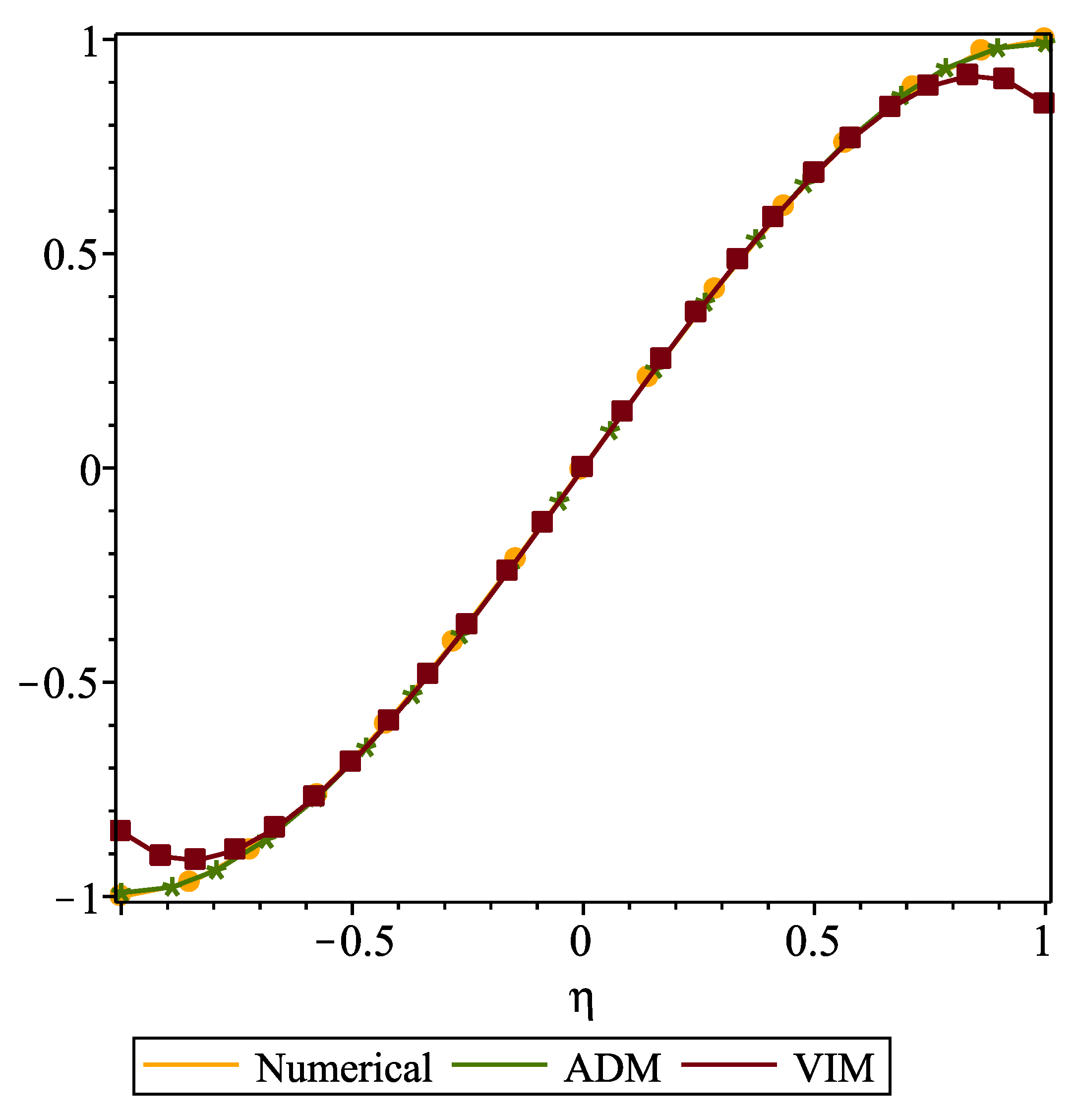
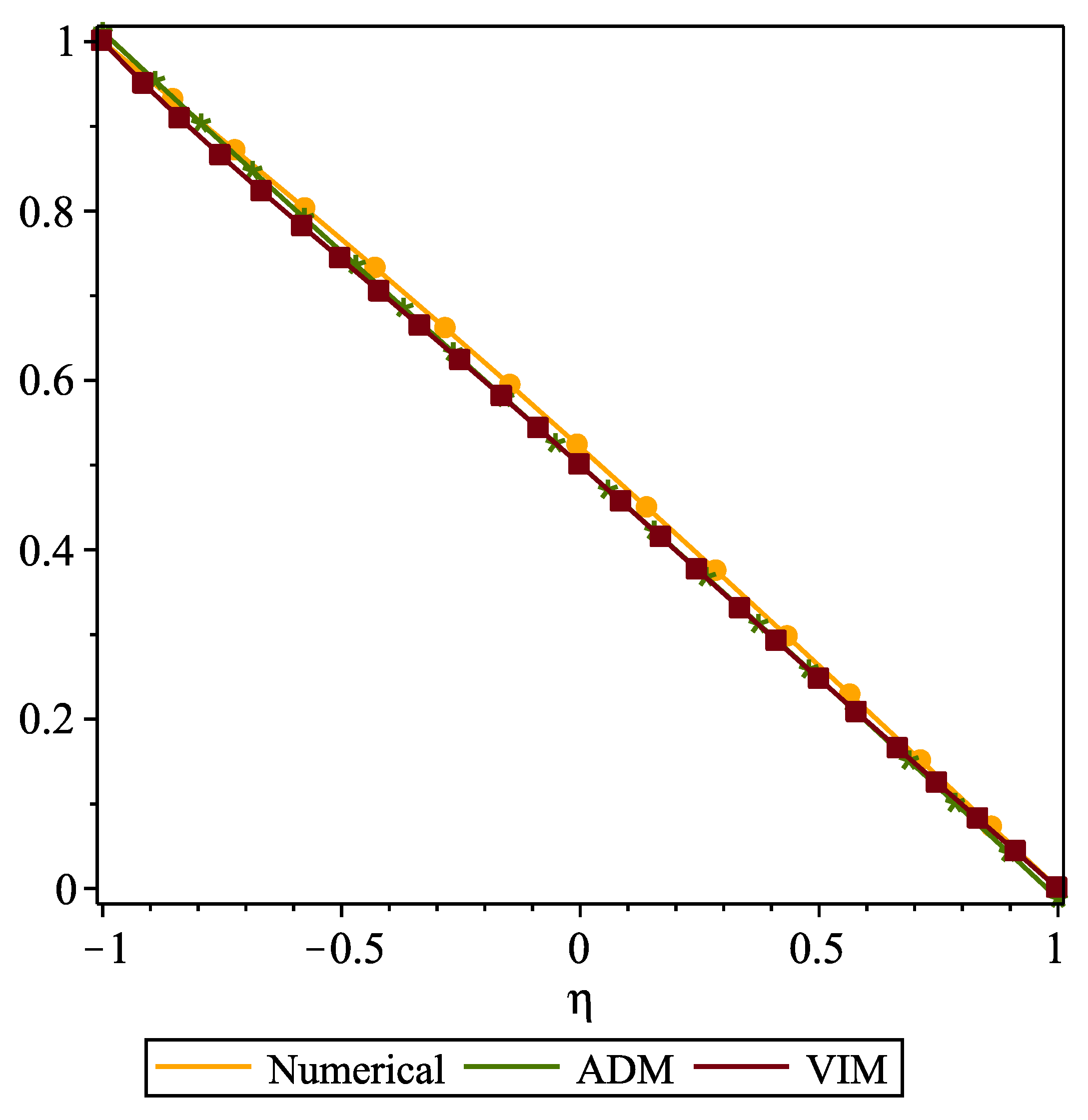
Figure 2 and Figure 3 exhibits the comparison sketch of velocity profile f ( η ) and temperature profile θ ( η ) for numerical (RK-45) and analytical (VIM and ADM) results for the parameters N 1 = N 2 = N 3 = P 0 = H a = N r = E c = 0.1 , P e h = P e m = 0.2 , R e = 1 , θ w = 1.01 , P r = 1 . The main calculations are mentioned in the Appendix A elaborately for both ADM and VIM formulations.
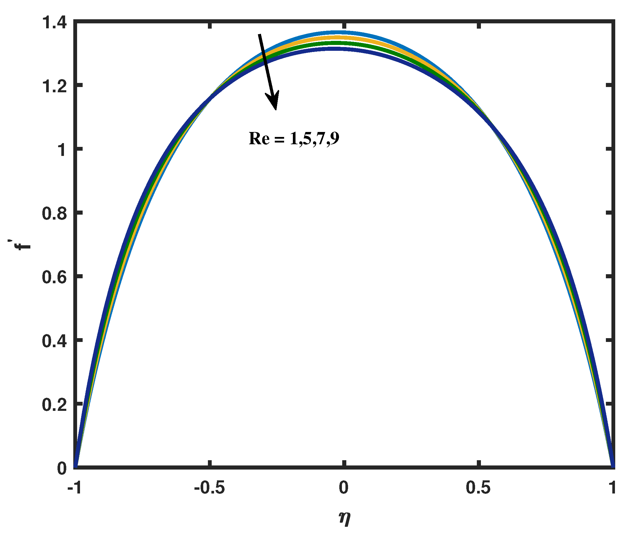
Figure 4 shows the influence of velocity profile over a Reynolds number. We can predict that when we increase the Reynolds number the velocity profile decreases. The fluid system whose viscosity significantly affects the flow pattern can be identified with the help of Reynolds number. Physically, as the liquid flow rate diminishes, the velocity declines as well. Here, the profile is fully obsessed by viscous force. The same trend prevails over the micro-rotation profile also.
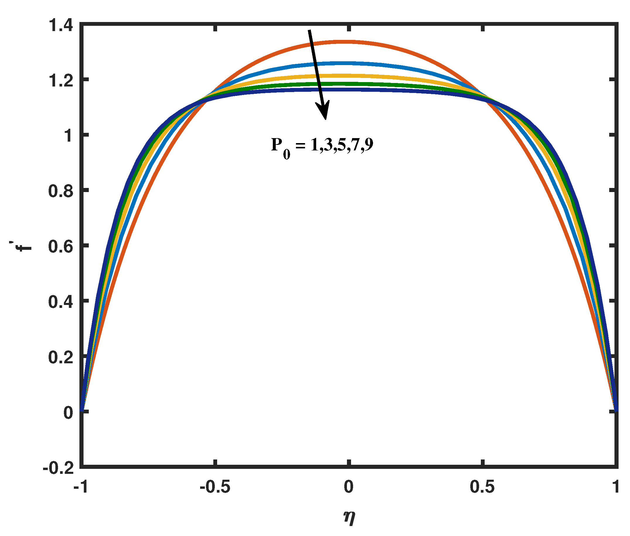
To show the influence of porosity parameter P 0 on the temperature profile Figure 5 is drawn. As expected the velocity profile decreases when enhancement in the porosity parameter. By making the channel’s surface more permeable, the velocity is dropped. The stoutness of the pores inside a permeable channel is connected to the rational explanation for such a diminishing trend. As a result, the fluid reacts with a repulsive force coming from the opposite direction of the flow fields, which causes the velocity boundary layer thickness to drop.
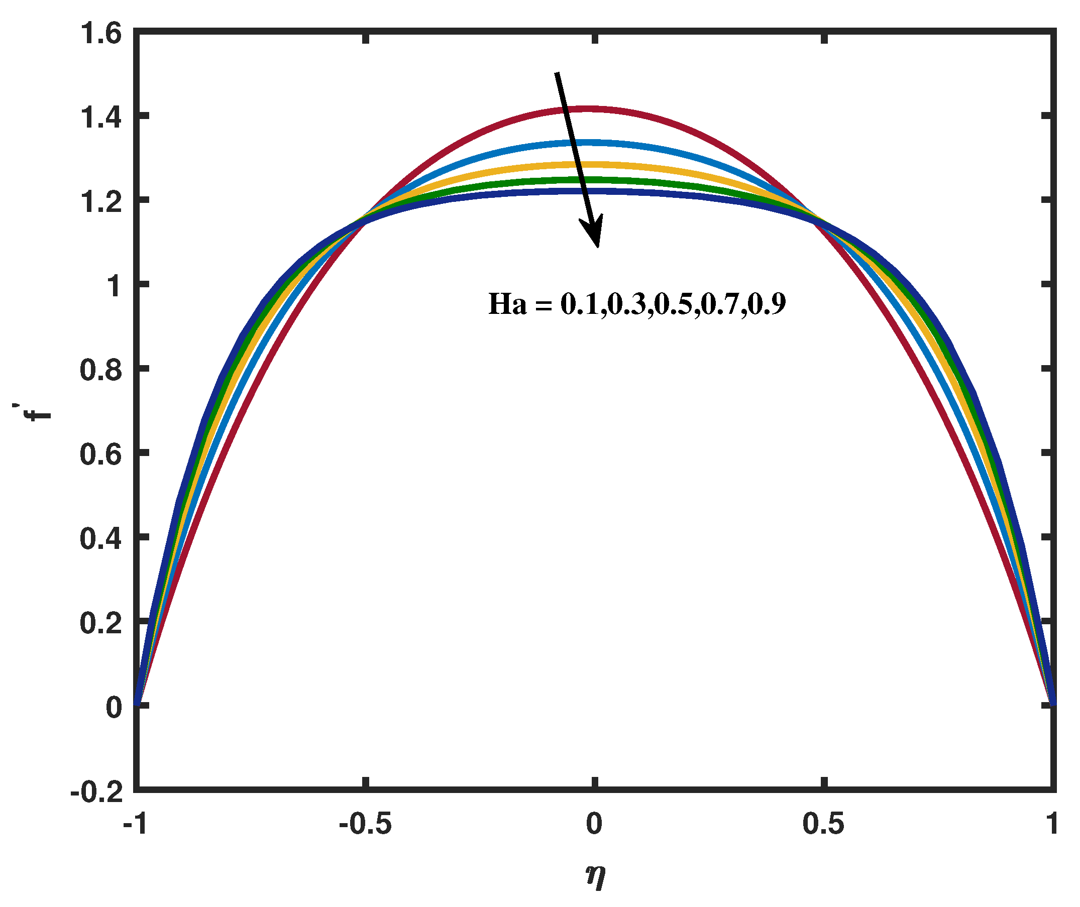
The influence of Magnetic factor H a over the velocity profile are depicted in the Figure 6. This figure shows the declining behavior in the velocity figure for various H a values. The astounding application of a transverse magnetic field, which produces a resistivity force known as the Lorentz force, which is comparable to the drag force which provide the physical explanation for this type of behavior. As a result, as H a rises, the drag force enhances, which causes the flow to slow down, so velocity decreases by increasing the magnetic character.
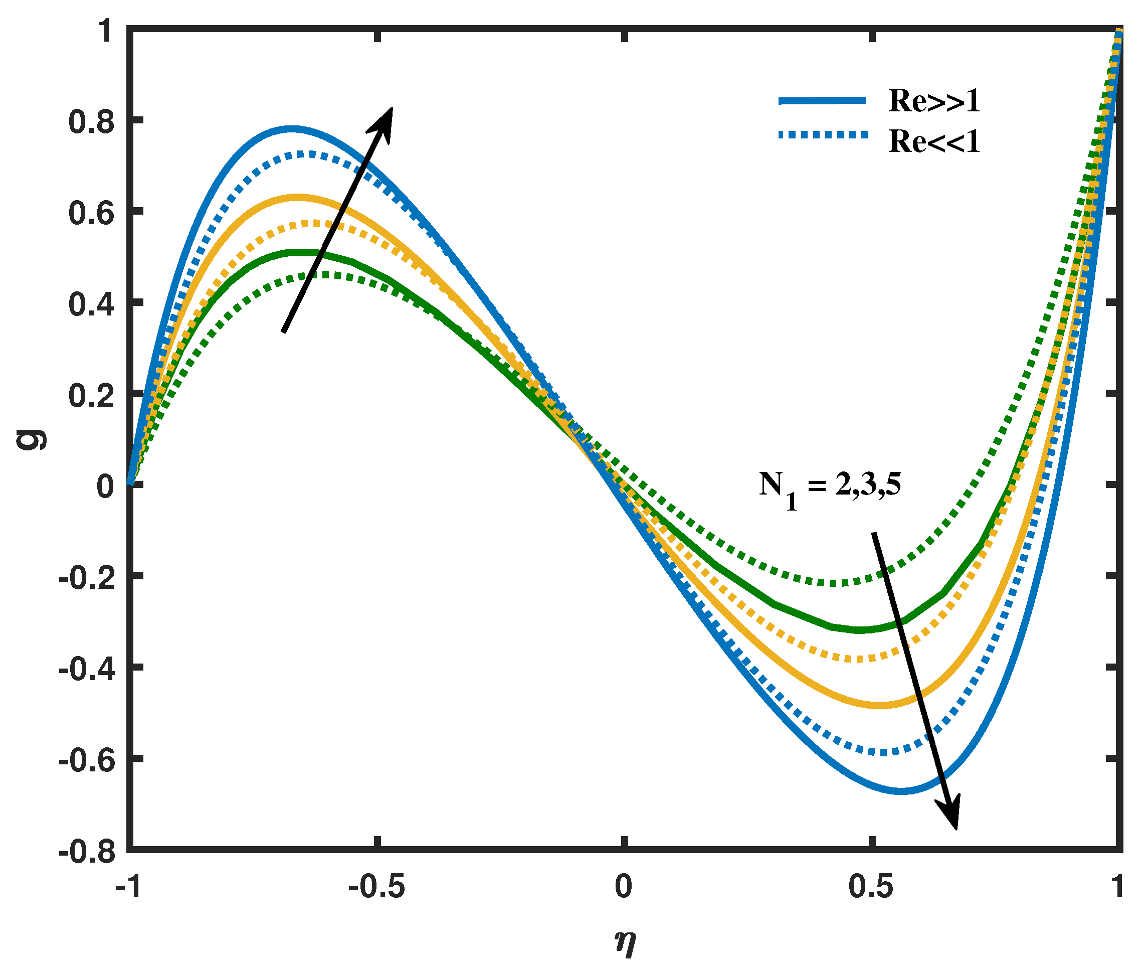
The micro-rotation profile for different coupling parameter or vortex viscosity parameter are sketched in Figure 7. From this outline, we can analyzed that the magnitude of micro-rotation tends to decrease when we increases the coupling parameter or vortex viscosity parameter. The micro-rotation profile gradually increases towards the lower plate of channel and behaves differently from the midsection of the plate close to the upper plate. Due to the particle’s delicate concentration the character N 1 attains Maximum rotation near the lower plate therefore this type of behavior exists in micro-rotation profile when enhancement in the vortex viscosity parameter N 1 .
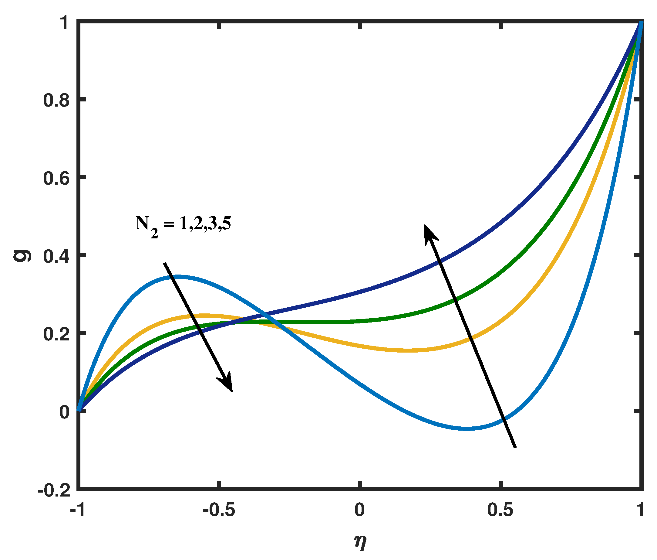
The effect of spin gradient viscosity parameter N 2 over an angular velocity profile is engrafted in Figure 8. An increasing trend is noted throughout the channel in the upper annulus. The micro-rotation function g accelerates close to the upper wall whereas it exhibiting the opposite retardation pattern close to the lower wall. The fluid’s spin gradient viscosity reduced as N 2 increased, which led to imperfections in the fluid particles motion. Figure 9 portrays the effect of micro inertia density parameter over a angular velocity profile. Here, the micro-rotation decreases for the higher factors of N 3 in upper wall however, it shows the opposite trend in lower wall. Furthermore the angular velocity profile changes the concavity somewhere near the midpoint of the channel for the magnetic parameter.
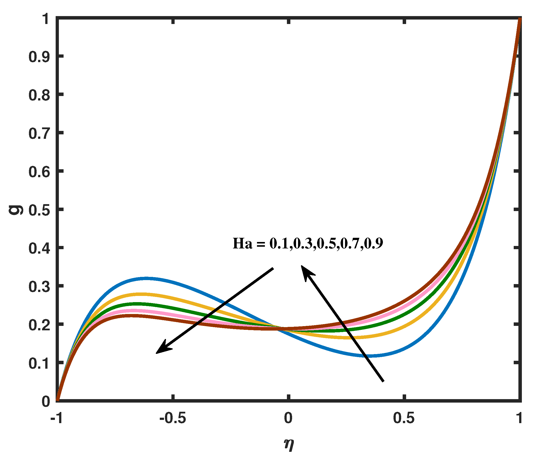
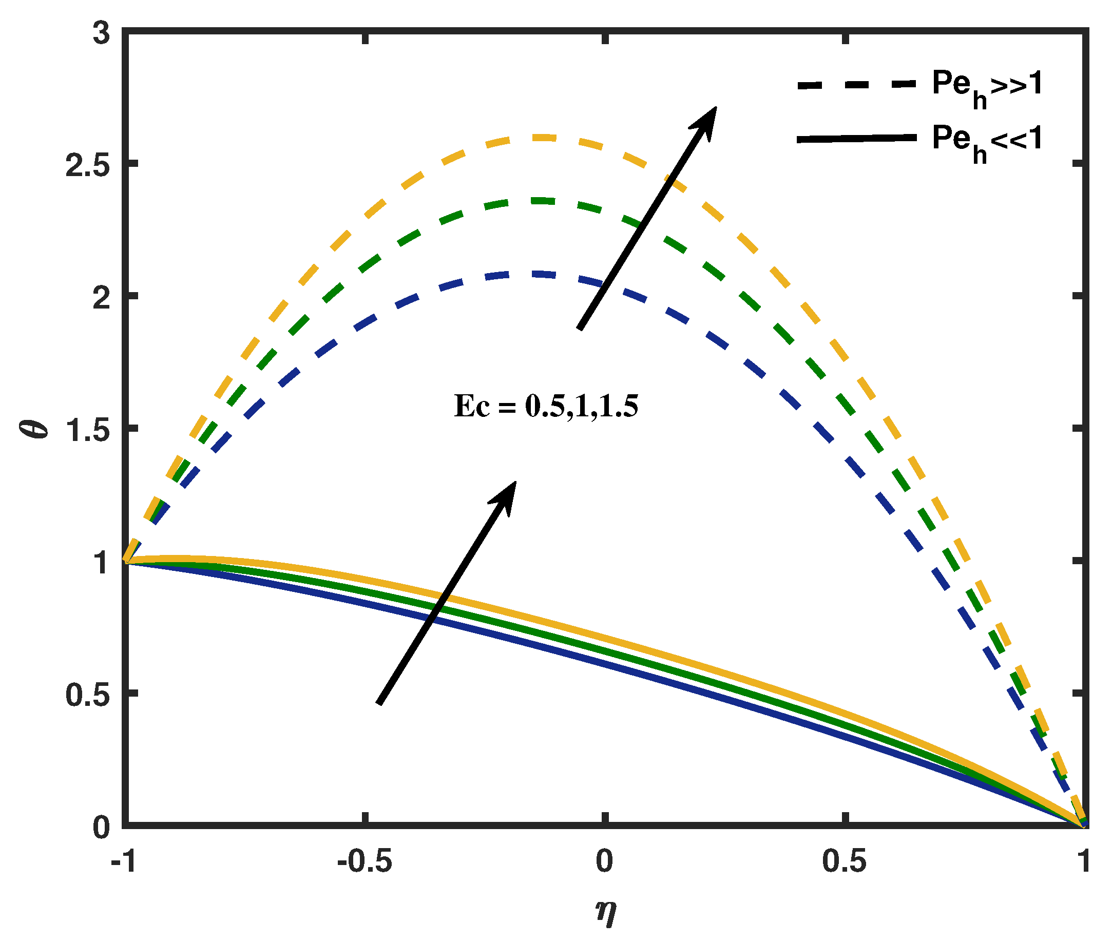
The influence of Magnetic parameter H a on the micro-rotation profile is manifested in Figure 10. The magnetic parameter increases in the upper wall whereas it decreases in the lower wall. The physical reason for this type of change in behavior is the Lorentz force which has a resistivity force equivalent to drag force that makes the fluid experience a resistance by increasing the friction between its layers and thus increases its micro-rotation near the upper wall. Figure 11 is sketched to show the effect of Eckert number E c for high and low values of heat transfer Peclet number on the dimensionless parameter θ ( η ) . The Peclet number for heat transfer P e h is the product of Reynolds number and Prandtl number. We can note that there is an increase in temperature profile when Prandtl and Reynolds number increases. Physically, the momentum diffusivity and inertial forces dominates vigorously in temperature profile due to this reason there is a surge in the temperature profile. From this figure we observed that the temperature profile increases when we increases viscous dissipation effects. According to the physical view the temperature profile and E c prevails a direct relationship with each other. The physical reason behind this type of scenario is that the Eckert number enhances the kinetic energy due to this inter molecular collision is increasing, so the temperature profile increases. Although Eckert number helps in the conversion of kinetic energy into internal energy by opposing fluid stresses. Therefore greater the viscous dissipative heat causes a rise in the temperature.
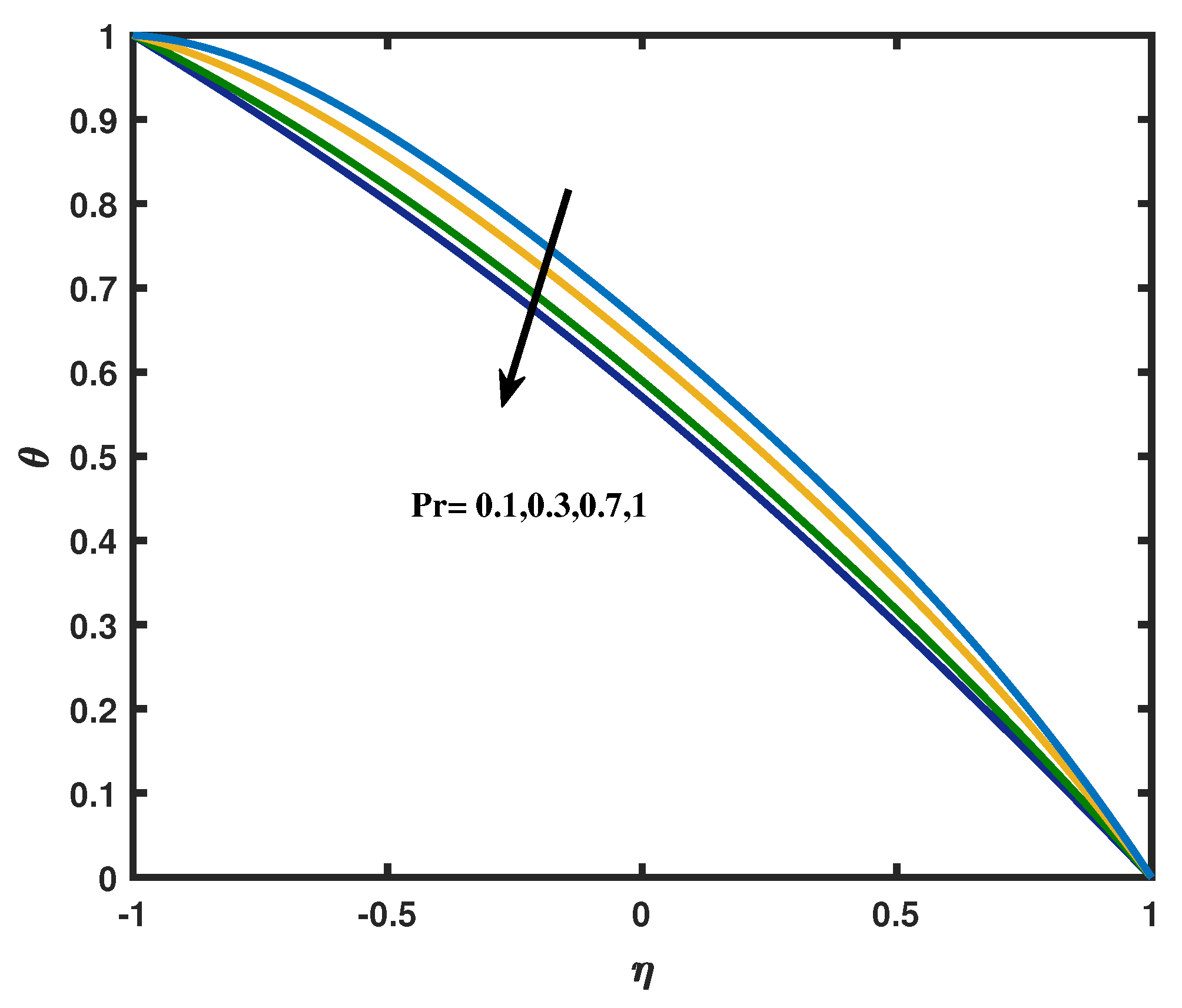
The variations in the Prandtl number against the temperature profile is predicted in Figure 12. Here, we noticed that an increase in the values of Prandtl number creates a reduction in the temperature profile. A rise in the Prandtl number corresponds to weaker thermal diffusivity. It is a well known fact that the fluids with weaker thermal diffusivity have lower temperature. Such weaker thermal diffusivity shows a reduction in the temperature and thermal boundary layer thickness. We also analyzed that fluid temperature enhances for increasing values of H a . In fact magnetic field is associated with Lorentz force which produces resistance to the motion of particles. Thus, more heat is produced. It consequently increases temperature and thermal boundary layer thickness.
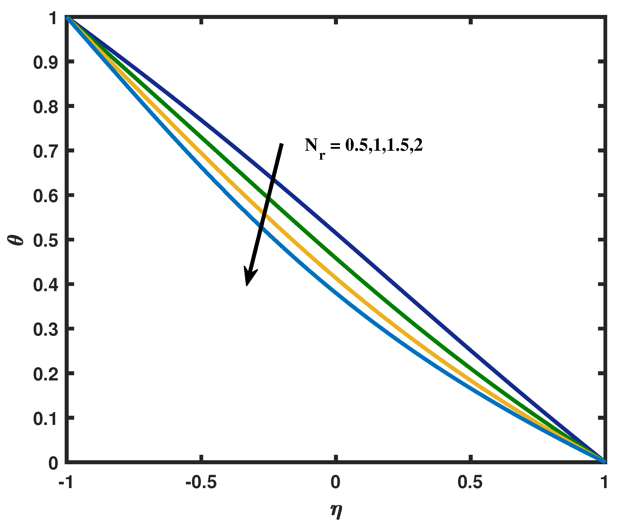
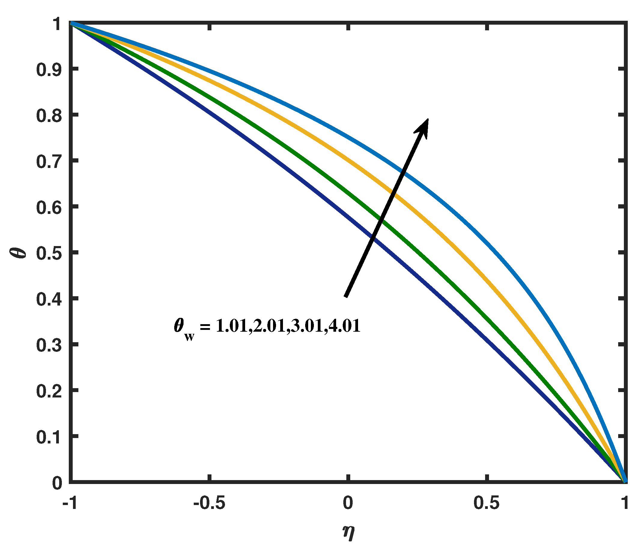
The variation of N r on the non dimensionalize temperature profile θ ( η ) is revealed in Figure 13. The temperature profile decreases when increasing the phenomenon of radiation N r . The fact explained for this type of result is that decrease in the radiation parameter R meant to be decrease in the Rosseland’s radiation absorptive. It is established that as the permittivity falls, the divergence of the radiative heat flow q r * y starts to rise which insinuates that the rate of radiative heat transferred to the fluid increases owing to this the temperature diminishes. Figure 14 is planted to obtain a clear view on the temperature profile for the temperature ratio parameter θ w . As expected the heating parameter boosts the temperature and thickness of the thermal boundary layer. This increasing behavior is perhaps because of the reason: As θ w = T 1 T 2 increases the operating temperature difference ( T 1 T 2 ) increases and this corresponds to the increases of the thermal state of the fluid resulting in increases in temperature profiles. Influence of P e m on concentration profile is represented in Figure 15. Peclet number for mass transfer is the product of Reynolds number and Schmidt number. From this figure we can analyze that there is a rapid increases in the concentration profile for the higher values of P e m . We can also observed that there will be a peak in the concentration for the P e m > > 1 due to more inertial force applied.
In Table 1, the outcomes are effectively compared with the existing articles of [35,36] for f ( η ) and θ ( η ) at N 1 = N 2 = N 3 = R e = P e h = P e m = 0.1 , P 0 = H a = N r = E c = 0 . Table 2 and Table 3 are mounted here in order to view the numerical and analytical results validation for f ( η ) and θ ( η ) for the parameters N 1 = N 2 = N 3 = P 0 = M g = R n = E c = 0.1 , P e h = P e m = 0.2 , R e = 1 , θ w = 1.01 , P r = 1 . Table 4 shows the skin friction values for various values of Reynolds number, vortex viscosity, porosity and magnetic parameter. It can be viewed that the skin friction values decreases when we increases Reynolds number in lower and upper wall. The skin friction values increases when increases the magnetic number in the lower wall whereas the reverse trend is noted in the upper wall. Table 5 is encrypted to show the Nusselt number values at various values of thermal radiation term, Eckert number, porosity and magnetic parameter. We can observed that the heat transfer rate increases in the lower wall and decreases in the upper wall correspondingly the Nusselt number decreases in the lower annulus and increases in the upper annulus for increasing values of Eckert number values. Table 6 displays the Sherwood number values for different mass transfer Peclet number, Reynolds number, porosity and magnetic number for the cases of high and low viscous force. From this table we can know that the Sherwood number increases in the lower annulus, however it decreases in upper annulus.

7. Concluding Remarks

We have envisioned a channel’s flow as having two permeable or porous walls. Between the channel’s walls, a porous material has also been taken into consideration. A distinctive aspect of our work is the simultaneous use of porous walls and a porous material in between these walls. In this prosecution, we studied MHD micropolar fluid flow with the impact of radiation and porosity along with the effects of viscous dissipation. Tables were included for a full examination and the leading parameters for this study are shown visually. Additionally, the Runge–Kutta-Fehlberg method and variational iteration, Adomian decomposition method are used to solve the nonlinear governed equations by numerically and analytically. The results are compared and tabulated with previous findings. Some of the key findings for this study are as follows:
  • The vortex viscosity parameter and spin gradient viscosity parameter shows the opposite reaction on micro-rotation profile.
  • The porosity parameter increases the surface drag, while its effect reduces the mass and thermal transit rates.
  • The presumptions obviously demonstrate that the micro-rotation and velocity are restrained by the porosity parameter and the Reynolds number.
  • Increasing the magnetic field opposing the fluid motion.
  • Increases the Eckert number rises the kinetic energy which enhances the temperature.
  • The effect of viscous dissipation is to increase the heat transfer rate.
  • The thermal radiation phenomena flattens the temperature and speeds up the heat transfer rate in the lower wall
  • Temperature distribution upgraded with increases in the temperature ratio parameter.
  • The skin friction values increases when increases the magnetic number in the lower wall whereas the reverse trend is noted in the upper wall.
  • The impact of thermal rays is essential in space technology and high temperature processes. At the point when the temperature variation is very high, the linear thermal radiation causes a noticeable error. To overcome such errors, nonlinear thermal radiation is taken into account.
  • VIM and ADM having high accuracy in solving nonlinear differential problems.

Author Contributions

M.S.: Roles/Writing—original draft; Writing—review & editing, Methodology, D.P.: Investigation, Validation, Formal analysis, P.D.: Software supervision. All authors have read and agreed to the published version of the manuscript.

Funding

This research received no external funding.

Data Availability Statement

Not applicable.

Conflicts of Interest

The authors declare no conflict of interest.

Appendix A

Appendix A.1. ADM Formulation

After implementing the parameters values N 1 = N 2 = N 3 = P 0 = H a = N r = E c = 0.1 , P e h = P e m = 0.2 , R e = 1 , θ w = 1.01 , P r = 1 , the governing Equations (11)–(14) are transformed as:
f ( η ) = 0.50 η 3 + 1.50 η 0.003571428571 η 7 0.005250000000 η 5 + 1.873126873 10 6 η 13 + 6.250000003 10 6 η 11 + 1.093750000 10 6 η 9
g ( η ) = 0.5 η + 0.5 0.06666666667 η 3 0.08750000000 η 2 + 0.003177083334 η 5 + 0.009166666667 η 4 0.0002395833334 η 7 0.0008541666665 η 6 + 5.208333333 10 6 η 9 + 0.00002343750000 η 8
θ ( η ) = 0.5 η + 0.5 + 0.00062500000 η 4 + 0.07500000000 η 2 + 0.01097500000 η 5 0.05000000000 η 3 + 0.00003750000001 η 8 0.0007821428571 η 7 + 0.001375000000 η 6 + 0.00008333333334 η 9
ϕ ( η ) = 0.5 η + 0.5 + 0.07500000000 η 2 + 0.009625000000 η 5 + 0.01437500000 η 4 0.05000000000 η 3 + 0.00008333333334 η 9 0.0001875000000 η 8 0.0006964285714 η 7 + 0.002125000000 η 6

Appendix A.2. VIM Formulataion

After implementing the parameters values N 1 = N 2 = N 3 = P 0 = H a = N r = E c = 0.1 , P e h = P e m = 0.2 , R e = 1 , θ w = 1.01 , P r = 1 , the governing Equations (11)–(14) are transformed as:
f ( η ) = 0.50 η 3 + 1.50 η 0.1250000000 η 7 0.02625000000 η 5
g ( η ) = 0.499999999999998 + 0.02500000000 η 5 + 0.0375000000000000 η 4 + 0.200000000000000 η 3 + 0.0125000000000006 η 2 + 0.499999999999998 η
θ ( η ) = 0.499999999999993 0.05000000000 η 5 0.0150000000000000 η 4 0.0749999999999848 η 2 0.500000000000004 η
ϕ ( η ) = 0.500000000000000 0.05000000000 η 5 + 0.0750000000000000 η 4 + 4.44089209850063 η 3 10 17 0.0749999999999998 η 2 0.500000000000000 η

References

  1. Eringen, A.C. Theory of micropolar fluids. J. Math. Mech. 1966, 16, 1–8. [Google Scholar] [CrossRef]
  2. Eringen, A.C. Theory of thermomicrofluids. J. Math. Anal. Appl. 1972, 38, 480–496. [Google Scholar] [CrossRef] [Green Version]
  3. Lukaszewicz, G. Micropolar Fluids: Theory and Applications; Springer Science & Business Media: Berlin/Heidelberg, Germany, 1999. [Google Scholar]
  4. Rana, B.M.; Arifuzzaman, S.M.; Islam, S.; Reza-E-Rabbi, S.; Al-Mamun, A.; Mazumder, M.; Roy, K.C.; Khan, M.S. Swimming of microbes in blood flow of nano-bioconvective Williamson fluid. Therm. Sci. Eng. Prog. 2021, 25, 101018. [Google Scholar] [CrossRef]
  5. Tetbirt, A.; Bouaziz, M.N.; Abbes, M.T. Numerical study of magnetic effect on the velocity distribution field in a macro/micro-scale of a micropolar and viscous fluid in vertical channel. J. Mol. Liq. 2016, 216, 103–110. [Google Scholar] [CrossRef]
  6. Pal, D.; Biswas, S. Magnetohydrodynamic convective-radiative oscillatory flow of a chemically reactive micropolar fluid in a porous medium. Propuls. Power Res. 2018, 7, 158–170. [Google Scholar] [CrossRef]
  7. Nisar, K.S.; Faridi, A.A.; Ahmad, S.; Khan, N.; Ali, K.; Jamshed, W.; Abdel-Aty, A.H.; Yahia, I.S. Cumulative impact of micropolar fluid and porosity on MHD channel flow: A numerical study. Coatings 2022, 12, 93. [Google Scholar] [CrossRef]
  8. Ashraf, M.; Kamal, M.A.; Syed, K.S. Numerical study of asymmetric laminar flow of micropolar fluids in a porous channel. Comput. Fluids 2009, 38, 1895–1902. [Google Scholar] [CrossRef]
  9. Turkyilmazoglu, M. A note on micropolar fluid flow and heat transfer over a porous shrinking sheet. Int. J. Heat Mass Transf. 2014, 72, 388–391. [Google Scholar] [CrossRef]
  10. Cao, L.; Si, X.; Zheng, L. The flow of a micropolar fluid through a porous expanding channel: A Lie group analysis. Appl. Math. Comput. 2015, 270, 242–250. [Google Scholar] [CrossRef]
  11. Lu, D.; Kahshan, M.; Siddiqui, A.M. Hydrodynamical study of micropolar fluid in a porous-walled channel: Application to flat plate dialyzer. Symmetry 2019, 11, 541. [Google Scholar] [CrossRef]
  12. Tiwari, A.; Shah, P.D.; Chauhan, S.S. Analytical study of micropolar fluid flow through porous layered microvessels with heat transfer approach. Eur. Phys. J. Plus 2020, 135, 1–32. [Google Scholar] [CrossRef]
  13. Siddheshwar, P.G.; Mahabaleshwar, U.S. Analytical solution to the MHD flow of micropolar fluid over a linear stretching sheet. Int. J. Appl. Mech. Eng. 2015, 20, 397–406. [Google Scholar] [CrossRef] [Green Version]
  14. Nandi, S.; Kumbhakar, B. Navier’s slip effect on Carreau nanouid flow past a convectively heated wedge in the presence of nonlinear thermal radiation and magnetic field. Int. Commun. Heat Mass Transf. 2020, 118, 104813. [Google Scholar] [CrossRef]
  15. Hayat, T.; Imtiaz, M.; Alsaedi, A.; Kutbi, M.A. MHD three-dimensional flow of nanofluid with velocity slip and nonlinear thermal radiation. J. Magn. Magn. Mater. 2015, 396, 31–37. [Google Scholar] [CrossRef]
  16. Animasaun, I.L.; Raju, C.S.; Sandeep, N. Unequal diffusivities case of homogeneous–heterogeneous reactions within viscoelastic fluid flow in the presence of induced magnetic-field and nonlinear thermal radiation. Alex. Eng. J. 2016, 55, 1595–1606. [Google Scholar] [CrossRef] [Green Version]
  17. Ramzan, M.; Chung, J.D.; Ullah, N. Radiative magnetohydrodynamic nanofluid flow due to gyrotactic microorganisms with chemical reaction and non-linear thermal radiation. Int. J. Mech. Sci. 2017, 130, 31–40. [Google Scholar] [CrossRef]
  18. Patel, H.R.; Singh, R. Thermophoresis, Brownian motion and non-linear thermal radiation effects on mixed convection MHD micropolar fluid flow due to nonlinear stretched sheet in porous medium with viscous dissipation, joule heating and convective boundary condition. Int. Commun. Heat Mass Transf. 2019, 107, 68–92. [Google Scholar] [CrossRef]
  19. Si, X.; Zheng, L.; Lin, P.; Zhang, X.; Zhang, Y. Flow and heat transfer of a micropolar fluid in a porous channel with expanding or contracting walls. Int. J. Heat Mass Transf. 2013, 67, 885–895. [Google Scholar] [CrossRef]
  20. Muthuraj, R.; Srinivas, S.; Shukla, A.K.; Ramamohan, T.R. Effects of Thermal Diffusion, Diffusion Thermo, and Space Porosity on MHD Mixed Convective Flow of Micropolar Fluid in a Vertical Channel with Viscous Dissipation. Heat Transf. Asian Res. 2014, 43, 561–576. [Google Scholar] [CrossRef]
  21. Sheri, S.R.; Shamshuddin, M.D. Heat and mass transfer on the MHD flow of micro polar fluid in the presence of viscous dissipation and chemical reaction. Procedia Eng. 2015, 127, 885–892. [Google Scholar] [CrossRef]
  22. Ahmad, S.; Ashraf, M.; Ali, K. Numerical simulation of viscous dissipation in a micropolar fluid flow through a porous medium. J. Appl. Mech. Tech. Phys. 2019, 60, 996–1004. [Google Scholar] [CrossRef]
  23. Algehyne, E.A.; Alrihieli, H.F.; Bilal, M.; Saeed, A.; Weera, W. Numerical approach toward ternary hybrid nanofluid flow using variable diffusion and non-Fourier’s concept. ACS Omega 2022, 7, 29380–29390. [Google Scholar] [CrossRef] [PubMed]
  24. Kataria, H.R.; Mistry, M.; Mittal, A. Influence of nonlinear radiation on MHD micropolar fluid flow with viscous dissipation. Heat Transf. 2022, 51, 1449–1467. [Google Scholar] [CrossRef]
  25. Khan, Z.; Rasheed, H.U.; Khan, I.; Abu-Zinadah, H.; Aldahlan, M.A. Mathematical simulation of casson MHD flow through a permeable moving wedge with nonlinear chemical reaction and nonlinear thermal radiation. Materials 2022, 15, 747. [Google Scholar] [CrossRef] [PubMed]
  26. He, J.H. Variational iteration method for autonomous ordinary differential systems. Appl. Math. Comput. 2000, 114, 115–123. [Google Scholar] [CrossRef]
  27. He, J.H. Variational iteration method some recent results and new interpretations. J. Comput. Appl. Math. 2007, 207, 3–17. [Google Scholar] [CrossRef] [Green Version]
  28. Lu, J. An analytical approach to the Fornberg Whitham type equations by using the variational iteration method. Comput. Math. Appl. 2011, 61, 2010–2013. [Google Scholar] [CrossRef] [Green Version]
  29. Adomian, G. A review of the decomposition method in applied mathematics. J. Math. Anal. Appl. 1988, 135, 501–544. [Google Scholar] [CrossRef] [Green Version]
  30. Ghosh, S.; Roy, A.; Roy, D. An adaptation of adomian decomposition for numeric analytic integration of strongly nonlinear and chaotic oscillators. Comput. Methods Appl. Mech. Eng. 2007, 196, 1133–1153. [Google Scholar] [CrossRef]
  31. Aski, F.S.; Nasirkhani, S.J.; Mohammadian, E.; Asgari, A. Application of Adomian decomposition method for micropolar flow in a porous channel. Propuls. Power Res. 2014, 3, 15–21. [Google Scholar] [CrossRef]
  32. Seny, O.; Rasmane, Y.; Loufouilou, J.M.; Pare, Y. Exact Analytical Solution of Some Volterra Second Kind Integrodifferential Equations by the Numerical Analysis Methods ADM and VIM. Adv. Dyn. Syst. Appl. (ADSA) 2021, 16, 1075–1096. [Google Scholar]
  33. Abed, A.M.; Younis, M.F.; Hamoud, A.A. Numerical Solutions of Nonlinear Volterra-Fredholm Integro-Differential Equations by using MADM and VIM. Nonlinear Funct. Anal. Appl. 2022, 27, 189–201. [Google Scholar]
  34. Pasha, P.; Nabi, H.; Peiravi, M.M.; Pourfallah, M.; Domiri Ganji, D. The application of analytical methods in the investigation effects of Magnetic parameter and Brownian motion on the fluid flow between two equal plates. Int. J. Eng. 2021, 34, 2341–2350. [Google Scholar]
  35. Mirzaaghaian, A.; Ganji, D.D. Application of differential transformation method in micropolar fluid flow and heat transfer through permeable walls. Alex. Eng. J. 2016, 55, 2183–2191. [Google Scholar] [CrossRef] [Green Version]
  36. Ahmad, S.; Ashraf, M.; Ali, K. Simulation of thermal radiation in a micropolar fluid flow through a porous medium between channel walls. J. Therm. Anal. Calorim. 2021, 144, 941–953. [Google Scholar] [CrossRef]
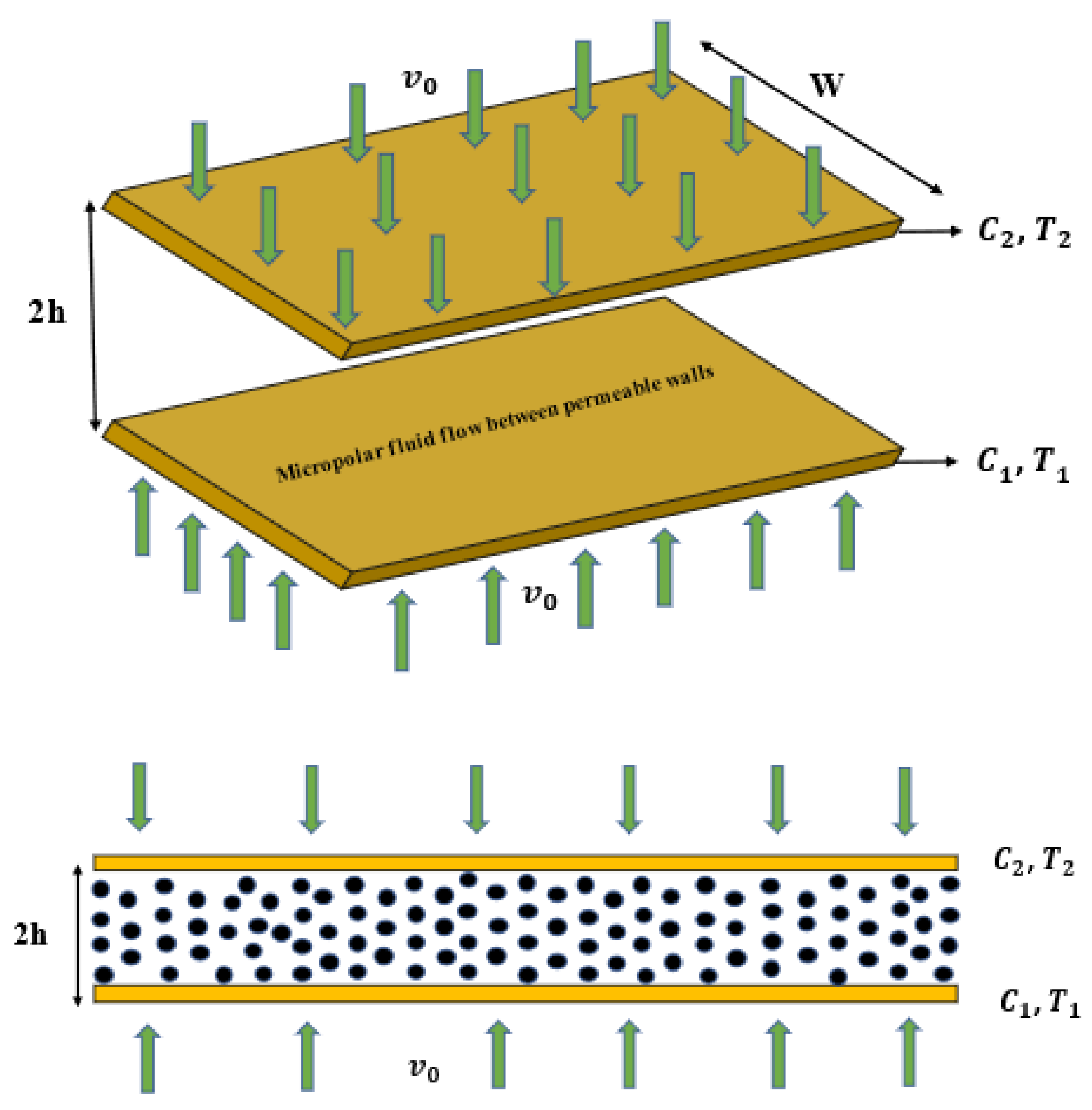
Figure 1. Physical representation of the problem.
Mathematics 11 00183 g001
Figure 2. Velocity profile f ( η ) compared with Numerical and Analytical results for the parameters N 1 = N 2 = N 3 = P 0 = M g = N r = E c = 0.1 , P e h = P e m = 0.2 , R e = 1 , θ w = 1.01 , P r = 1 .
Mathematics 11 00183 g002
Figure 3. Temperature profile θ ( η ) compared with Numerical and Analytical results for the parameters N 1 = N 2 = N 3 = P 0 = M g = N r = E c = 0.1 , P e h = P e m = 0.2 , R e = 1 , θ w = 1.01 , P r = 1 .
Mathematics 11 00183 g003
Figure 4. Velocity profile for varied R e .
Mathematics 11 00183 g004
Figure 5. Velocity profile for various values of porosity parameter P 0 .
Mathematics 11 00183 g005
Figure 6. Velocity profile for different magnetic number H a .
Mathematics 11 00183 g006
Figure 7. Micro-rotation for different N 1 with high and low viscous force.
Mathematics 11 00183 g007
Figure 8. Micro-rotation versus spin gradient viscosity parameter N 2 .
Mathematics 11 00183 g008
Figure 9. Variation in Micro inertia density parameter N 3 for high and low viscous force.
Mathematics 11 00183 g009
Figure 10. Micro-rotation versus Magnetic parameter H a .
Mathematics 11 00183 g010
Figure 11. Temperature profile for different values of Eckert number with high and low levels of Peclet number for heat transfer P e h .
Mathematics 11 00183 g011
Figure 12. Temperature profile for different values of Prandtl number.
Mathematics 11 00183 g012
Figure 13. Temperature profile for various values of radiation parameter N r .
Mathematics 11 00183 g013
Figure 14. Temperature profile for different levels of temperature ratio parameter θ w .
Mathematics 11 00183 g014
Figure 15. Concentration profile for various values of Peclet number for mass transfer P e m .
Mathematics 11 00183 g015
Table 1. Comparison table for f ( η ) and θ ( η ) at N 1 = N 2 = N 3 = R e = P e h = P e m = 0.1 , P 0 = H a = N r = E c = 0 .
η Numerical Results
f ( η ) θ ( η )
Present ResultsLiterature [35]Literature [36]Present ResultsLiterature [35]Literature [36]
−1−0.999999−1−10.99999911
−0.8−0.943910−0.943889−0.9438530.9095910.9095620.909561
−0.6−0.791605−0.791757−0.7915990.8189700.8189140.818912
−0.4−0.567102−0.567738−0.2956860.7266880.7266100.726605
−0.20.6211600.6211650.6211600.6318310.6317420.631734
00.00197008.14 × 10−130.5339230.5338350.533825
0.20.2981570.2958350.2956860.4328230.4327420.432737
0.40.5699150.5677380.5675240.3286310.3285710.328563
0.60.7932620.7917570.7915990.2215840.2215440.221538
0.80.9444450.9438890.9438530.1119650.1119450.111942
1111000
Table 2. Numerical and Analytical results validation for f ( η ) for the parameters N 1 = N 2 = N 3 = P 0 = H a = N r = E c = 0.1 , P e h = P e m = 0.2 , R e = 1 .
η f ( η ) NUM f ( η ) ADM f ( η ) VIM
−1−1−0.991187−0.848750
−0.8−0.942612−0.941534−0.909184
−0.6−0.788848−0.791491−0.786459
−0.4−0.564296−0.567940−0.567526
−0.2−0.293073−0.295998−0.295990
00.00129400
0.20.2954830.2959980.295990
0.40.5661960.5679400.567526
0.60.7900070.7917910.786459
0.80.9430050.9415310.909184
110.9911870.848750
Table 3. Numerical and Analytical results validation for θ ( η ) for the parameters N 1 = N 2 = N 3 = P 0 = h a = N r = E c = 0.1 , P e h = P e m = 0.2 , R e = 1 .
η θ ( η ) NUM θ ( η ) ADM θ ( η ) VIM
−111.0116931.000000
−0.80.9077830.9068920.889632
−0.60.8143410.8032080.790784
−0.40.7189100.7010140.695296
−0.20.6211600.6001310.598848
00.5211080.5000000.500000
0.20.4190320.3998680.399232
0.40.3153800.2989850.297984
0.60.2106770.1967910.197696
0.80.1054250.0931070.098848
10−0.011693−0.000001
Table 4. Table values for skin-friction at various values of R e , N 1 , P 0 , H a .
Re N 1 P 0 Ha f ( 1 ) f ( + 1 )
0.110.10.13.03075693−2.9140140
0.33.05059889−2.9346138
0.53.07033151−2.9550899
10.13.20550833−3.09510636
0.33.22441278−3.11465427
0.53.24321921−3.13409317
30.10.12.96246626−2.61024483
0.32.97243614−2.62136373
0.52.98237963−2.6324449
10.13.13799613−2.80485426
0.33.14751138−2.81533854
0.53.15700259−2.82579014
310.10.12.63571963−3.54554686
0.32.66932666−3.56240713
0.52.7023711−3.57937237
10.12.92141356−3.69995395
0.32.95109937−3.71734373
0.52.98042261−3.73475378
30.10.12.93011104−2.60797715
0.32.94159375−2.62055067
0.52.95303829−2.6330743
10.13.13116496−2.82702306
0.33.14199858−2.83876397
0.53.15279838−2.85046238
Table 5. Table values for Nusselt number at various values of N r , E c , P 0 , H a .
N r Ec P 0 Ha θ ( 1 ) θ ( + 1 )
0.50.50.10.1−0.522354551.12730298
0.3−0.563533781.15291334
0.5−0.604621491.17848312
10.1−0.505486281.11587118
0.3−0.546118741.14117643
0.5−0.586685871.16645647
10.10.1−1.287490581.60590433
0.3−1.370114731.65773933
0.5−1.452542321.70946438
10.1−1.255173841.58527646
0.3−1.336690371.63646255
0.5−1.418065121.68759003
1.50.50.10.1−0.229779730.65968306
0.3−0.270176150.67421018
0.5−0.310534660.68873936
10.1−0.215917000.65463068
0.3−0.255751870.66899326
0.5−0.295569430.68336359
10.10.1−0.984662420.93321072
0.3−1.067037830.96337151
0.5−1.108203330.97845345
10.1−0.954666860.92270556
0.3−1.035831610.95242927
0.5−1.116920930.98218711
2.50.50.10.10.028443840.47956902
0.3−0.010279700.48928915
0.5−0.048999510.49901518
10.10.038708080.47716153
0.30.000457470.48680983
0.5−0.037808570.49646556
1.50.10.1−0.696517620.66164154
0.3−0.776724600.68193716
0.5−0.816841140.69210542
10.1−0.671443350.65622783
0.3−0.750383080.67625805
0.5−0.829409280.69634174
Table 6. Table values for Sherwood number at various values of R e , P e m , P 0 , H a .
Re Pe m P 0 M ϕ ( 1 ) ϕ ( + 1 )
0.50.50.110.090495911.01213098
30.091960381.00934866
50.093311741.00672027
210.095499661.00233443
30.096597811.00006941
50.097623070.99791445
2.50.113.18338485−1.4665947
33.18830548−1.4828353
53.19322282−1.4986293
213.20203016−1.5259728
33.20688324−1.5405845
53.21169920−1.5548001
50.50.110.116059911.00085941
30.114994360.99886207
50.11426621.0.99685709
210.113520000.99331531
30.113317700.99141162
50.113218570.98956335
2.50.113.14123546−1.3900296
33.15022379−1.4158994
53.15868590−1.4399207
213.17287387−1.4794332
33.18028355−1.4996793
53.18740999−1.5188976
Disclaimer/Publisher’s Note: The statements, opinions and data contained in all publications are solely those of the individual author(s) and contributor(s) and not of MDPI and/or the editor(s). MDPI and/or the editor(s) disclaim responsibility for any injury to people or property resulting from any ideas, methods, instructions or products referred to in the content.