Article

Adaptive Control for an Aircraft Wing System with Hysteresis Nonlinearity

School of Electrical Engineering and Intelligentization, Dongguan University of Technology, Dongguan 523000, China
*
Author to whom correspondence should be addressed.
Mathematics 2023, 11(18), 3841; https://doi.org/10.3390/math11183841
Submission received: 22 July 2023 / Revised: 1 September 2023 / Accepted: 5 September 2023 / Published: 7 September 2023
(This article belongs to the Special Issue Deep Learning and Adaptive Control, 2nd Edition)

Abstract

:
This paper involves a novel adaptive control approach of a flexible wing system with hysteresis nonlinearity. The usual control design strategies based on the ordinary differential equations (ODEs) are inapplicable due to the flexible wing system described in the partial differential equations (PDEs), and the design of the control algorithm becomes highly intricate. Firstly, the inverse dynamic model of hysteresis is introduced to compensate for the hysteresis nonlinearity. Considering the unknown external disturbances, an adaptive technique is utilized for compensation. Then, the direct Lyapunov approach is employed to prove the bounded stability of the system. Lastly, the effectiveness of the proposed approach is validated via simulation results.

1. Introduction

In recent years, aircraft have been widely utilized in various fields due to their flexibility, high maneuverability, and expansive vision [1,2,3,4]. Among them, flapping-wing aircraft stands out for its special strengths, including excellent aerial agility and low energy consumption, attracting increasing attention from researchers [5,6,7]. To fully exploit the potential of flapping-wing aircraft, scholars have combined structural design with biomimicry principles and employed flexible materials for wing fabrication. This approach aims to enhance the aircraft’s performance by improving its flexibility and reducing operational failures. However, wing vibrations and deformations arising from flexible wings can impact the control effectiveness and flight performance [8,9,10]. Consequently, addressing wing vibration has become a pressing issue inspiring further research. In this paper, we regard a single wing as a distributed parameter system (DPS) and use PDEs to describe the wing dynamic model [11,12,13]. DPS is a type of dynamic system that exhibits properties distributed in both time and space. Unlike discrete parameter systems (such as common control systems), one of the distinguishing features of distributed parameter systems is that their state variables or control inputs vary not only with time but also with spatial location. The complex control design of DPSs has garnered increasing attention in recent years.
In the face of mitigating vibrations in DPSs based on PDEs, researchers have proposed various control strategies in their studies, such as modal reduction strategy [14] and boundary control approaches [15,16]. The modal reduction method is a mathematical technique used to simplify complex dynamic systems. It is typically applied to systems with a large number of degrees of freedom or state variables, such as structural dynamics, vibration analysis, and distributed parameter systems in control engineering. The primary objective of the modal reduction method is to reduce a high-dimensional system to a lower-dimensional subspace, reducing computational complexity while preserving the critical dynamic characteristics of the system. The modal reduction method has proven to be effective in reducing infinite-dimensional systems to finite dimensions. However, it should be noted that this approach can sometimes result in spillover effects, as highlighted in [17]. As an alternative option, the implementation of the boundary control strategy has been demonstrated to be highly effective in enhancing system robustness. The boundary control strategy is a design approach for control systems typically used in distributed parameter systems or systems with continuous-domain dynamic characteristics. The central idea of this strategy is to influence the behavior of the entire system by applying suitable control over the system’s boundaries (or boundary conditions). Over the past decade, substantial advancements have been accomplished in the domain of vibration suppression in flexible structural systems using boundary control methods. For instance, in [18], an innovative adaptive fault-tolerant control approach was devised to mitigate the vibrations of the flexible panel during attitude stabilization. In [19], an innovative adaptive control approach was implemented to mitigate the vibrations of a riser-vessel system. A novel quantized adaptive integral sliding mode control method was addressed to ensure the global asymptotic stability of flexible structures [20]. However, the research on boundary control methods for suppressing flexible wing vibrations is still lacking, which has motivated this study.
Hysteresis is a dynamic nonlinearity commonly observed in electronic, electromagnetic, and mechanical actuators, among other domains [21,22,23]. In systems requiring high control accuracy, hysteresis can introduce phase shifts and harmonic distortions that affect the integrity of input signal information, leading to unstable control systems. To address this issue, numerous approaches have been designed by scholars to alleviate the impact of hysteresis. These methods aim to compensate for hysteresis effects using techniques such as pre-compensation, inverse modeling, and feedback control. By employing these strategies, researchers strive to enhance the control system stability and improve the overall performance in the presence of hysteresis. In [24], the investigation focused on examining the detrimental impact of the actuator hysteresis on the stability of networked control systems. To tackle this problem, they employed a first-order filter as a solution. A hierarchical sliding mode control scheme was proposed to account for both external disturbances and hysteresis nonlinearity in [25]. A perfect inverse dynamics was suggested to counteract hysteresis effects in the Bouc–Wen hysteresis model in [26]. Nevertheless, the previously mentioned unknown hysteresis inverse control technique was primarily developed for systems described via ODEs and is not directly applicable to infinite-dimensional flexible wing systems with unknown hysteresis. Based on our current understanding, though substantial advancements have been made in the field of inverse control for ODE systems with hysteresis nonlinearity, there has been limited exploration in addressing the collective influence of hysteresis nonlinearity in flexible wing systems. This serves as a driving force for us to address this research gap and seek a solution.
This paper aims to examine the stability of flexible wing systems under the influence of hysteresis nonlinearity and unknown disturbances. The following provides a brief overview of the main contributions: (i) The model is enhanced to incorporate the presence of unknown boundary disturbances affecting the flexible wing. This update enables a more comprehensive understanding of the system’s behavior under real-world conditions. (ii) An adaptive controller is proposed to compensate for the unknown boundary disturbances. In contrast to previous studies [27,28], the proposed controller utilizes an inverse strategy to effectively address the input hysteresis effect in the flexible wing. Consequently, the overall performance of the system is improved. (iii) By effectively resolving the vibration problem inherent in wing structures, the proposed approach ensures that the system control does not exhibit any spillover effect [17]. This accomplishment plays a vital role in preserving stability and optimizing the overall performance of the interconnected flexible wing system.

2. Problem Statement

2.1. System Depiction

Figure 1 illustrates a flexible flapping-wing system exposed to unidentified disturbances. The following symbols are specified in this paper: x e c shows the offset from the wing cross-section’s mass center to its shear center. The aerodynamic center offset from the shear center of the wing is represented by x a c . ρ signifies the density of the wing, I p denotes the axial moment of inertia of the flexible wing cross-section, E I b represents the bending rigidity, G J is the torsion rigidity, g h ( r , t ) denotes the distributed disturbance, R denotes the set of real numbers, u 1 ( t ) and u 2 ( t ) symbolize the control inputs, and ξ indicates the damping coefficient. Additionally, g 1 ( t ) and g 2 ( t ) are the unidentified disturbances at the wing tip r = l . To simplify the presentation, certain symbols have been substituted with ( · ) ˙ = ( · ) / t , ( · ) = ( · ) / r , ( · ) ˙ = 2 ( · ) / r t , ( · ) = 2 ( · ) / r 2 , and ( · ) ¨ = 2 ( · ) / t 2 .
Let z ( r , t ) and Θ ( r , t ) denote the bending and twist displacements, respectively. Firstly, the dynamical model of the system is considered as follows [29]:
I p Θ ¨ ( r , t ) G J Θ ( r , t ) ρ x e c z ¨ ( r , t ) ξ G J Θ ˙ ( r , t ) = x a c g h ( r , t ) ,
ρ z ¨ ( r , t ) + E I b z ( r , t ) ρ x e c Θ ¨ ( r , t ) + ξ E I b z ˙ ( r , t ) = g h ( r , t ) ,
z ( 0 , t ) = z ( 0 , t ) = z ( l , t ) = Θ ( 0 , t ) = 0 ,
E I b z ( l , t ) + ξ E I b z ˙ ( l , t ) = u 1 ( t ) + g 1 ( t ) ,
G J Θ ( l , t ) + ξ G J Θ ˙ ( l , t ) = u 2 ( t ) + g 2 ( t ) .

2.2. Hysteresis Characteristic Analysis

This study considers the existence of hysteresis in the actuator input of the system, specifically the Bouc–Wen hysteresis model [22]. The model is widely accepted for describing the rate-dependent hysteresis and the formulation is defined as follows [26]:
u j ( t ) = H ( τ j ( t ) ) = μ j κ j τ j + ( 1 μ j ) κ j ζ j = μ 1 j τ j + μ 2 j ζ j ,
where 0 < μ j < 1 , j = 1 , 2 , represent the stiffness ratio, τ j , j = 1 , 2 , delineate the anticipated control to be developed, and κ j , j = 1 , 2 , are the parameters associated with the pseudo natural frequency. The unknown constants μ 1 j and μ 2 j , j = 1 , 2 , have the same sign. Additionally, ζ j R , j = 1 , 2 , are rate-dependent variables dependent on the inputs τ j , j = 1 , 2 , and its derivative τ ˙ j , j = 1 , 2 , and the form are presented as follows [26]:
ζ ˙ j = τ ˙ j β j | τ ˙ j | | ζ j | n j 1 ζ j χ j τ ˙ j | ζ j | n j = τ ˙ j f ( ζ j , τ ˙ j ) ,
f ( ζ j , τ ˙ j ) = 1 sgn ( τ ˙ j ) β j | ζ j | n j 1 ζ j χ j | ζ j | n j ,
where β j > | χ j | and n j 1 , j = 1 , 2 , represent the parameters describing the shape, amplitude, and smoothness of hysteresis nonlinearity, respectively.
Remark 1.
In [30], a novel boundary method was introduced for DPSs featuring hysteresis. The authors presented a hysteresis model that is a specific instance of the hysteresis model described by (6) in this paper.
To address hysteresis nonlinearity, we introduce the following inverse dynamics [26]:
τ j ( t ) = H I ( u d j ) = 1 μ 1 j u d j μ 2 j μ 1 j ζ 1 j ,
ζ ˙ 1 j = u ˙ d j μ 1 j + μ 2 j f ( ζ 1 j , u ˙ d j μ 1 j ) f ( ζ 1 j , u ˙ d j μ 1 j ) , ζ 1 j ( t 0 ) = 0 ,
τ ˙ j ( t ) = u ˙ d j μ 1 j + μ 2 j f ( ζ 1 j , u ˙ d j μ 1 j ) ,
where u d j , j = 1 , 2 , represent the designed control signals, and the function f ( ) is defined in (8).

2.3. Preliminaries

Assumption 1.
We make the assumption that there are positive constants G 1 , G 2 , and g h m a x such that | g 1 ( t ) | G 1 , | g 2 ( t ) | G 2 , and | g h ( r , t ) | g h m a x , for all ( r , t ) [ 0 , l ] × [ 0 , + ) .
Lemma 1.
([31]). If there exist two real numbers ϖ 1 ( r , t ) and ϖ 2 ( r , t ) , p > 0 with ( r , t ) [ 0 , l ] × [ 0 , + ) , the following expression can be derived:
ϖ 1 ϖ 2 1 p ϖ 1 2 + p ϖ 2 2 .
Lemma 2.
([31]). If ϖ ( r , t ) R , and ( r , t ) [ 0 , l ] × [ 0 , + ) , which satisfying the condition ϖ ( 0 , t ) = 0 , we can express it as follows:
ϖ 2 l 0 l ϖ 2 d r ,
where ( z , t ) [ 0 , l ] × [ 0 , + ) .
Lemma 3.
Considering the nonlinear dynamic system (10), the following results hold for any piecewise smooth signals u j and u ˙ j : (i) The output signal ζ 1 j ( t ) , j = 1 , 2 , remain bounded within the limit specified by | ζ j ( t ) | < 1 / ( β j + χ j ) n j , j = 1 , 2 . (ii) For ζ 1 j ( t 0 ) = 0 , s g n ( ζ 1 j ) = s g n ( τ j ) = s g n ( u j μ 1 j ) , j = 1 , 2 .
Proof. 
Using the Equation ( 7 ) and Lyapunov function W ζ j ( t ) = ζ j 2 ( t ) 2 , j = 1 , 2 , and introducing the notation ζ j m = 1 β j + χ j n j , j = 1 , 2 , the application of Gronwall’s lemma demonstrates that W ˙ ζ j 0 for all ζ j ζ j m , j = 1 , 2 . Consequently, we can deduce that ζ j ( t ) is bounded for every piecewise function τ ˙ j and every initial condition ζ j ( t 0 ) . Moreover, since the initial condition of ζ j is ζ j ( t 0 ) = 0 ζ j m , it follows that ζ j ζ j m , j = 1 , 2 , for all t t 0 .
ζ ˙ j = τ ˙ j ( 1 ( s g n ( ζ j ) s g n ( τ ˙ j ) β j + χ j ) ζ j n j ) ,
It is noted that the term ( 1 ( sgn ( ζ j ) sgn ( τ ˙ j ) β j + χ j ) ζ j n j ) 0 , j = 1 , 2 , due to the fact that we have ζ j 1 β j + χ j n j , j = 1 , 2 . Thus,
τ ˙ j > 0 ζ ˙ j > 0 τ ˙ j < 0 ζ ˙ j < 0 τ ˙ j = 0 ζ ˙ j = 0 .
It can be inferred from the inequality ( 1 ( sgn ( ζ j ) sgn ( τ ˙ j ) β j + χ j ) ζ j n j ) 0 that f ( ζ 1 j , u ˙ d j μ 1 j ) 0 and 1 + μ 2 j μ 1 j f ( ζ 1 j , u ˙ d j μ 1 j ) > 0 since μ 2 j μ 1 j > 0 . Then ( 10 ) can be rewritten as
ζ ˙ 1 j ( 1 + μ 2 j μ 1 j f ( ζ 1 j , u ˙ d j μ 1 j ) ) = u ˙ d j μ 1 j f ( ζ 1 j , u ˙ d j μ 1 j ) .
Through similar analysis, it can shown that
u ˙ d j μ 1 j > 0 ζ ˙ j > 0 , τ ˙ j > 0 u ˙ d j μ 1 j < 0 ζ ˙ j < 0 , τ ˙ j < 0 u ˙ d j μ 1 j = 0 ζ ˙ j = 0 , τ ˙ j = 0 .

3. Control Design

This section outlines the methodology employed for designing boundary controllers to efficiently attenuate the vibrations in a wing system. To achieve this control objective, an adaptive control scheme is employed, which guarantees the stability of the closed-loop system.
First, the boundary control strategies are proposed as indicated:
u d 1 ( t ) = k 1 [ a z ( l , t ) + b z ˙ ( l , t ) ] g ^ 1 ( t ) ,
u d 2 ( t ) = k 2 [ a Θ ( l , t ) + b Θ ˙ ( l , t ) ] g ^ 2 ( t ) ,
where a , b , k 1 , and k 2 are positive numbers, and g ^ 1 ( t ) , g ^ 2 ( t ) denote the estimates of the boundary disturbances.
Step 1. The design of the dynamic adaptive update laws is formulated as follows:
g ^ ˙ 1 ( t ) = γ 1 [ a z ( l , t ) + b z ˙ ( l , t ) ] ,
g ^ ˙ 2 ( t ) = γ 2 [ a Θ ( l , t ) + b Θ ˙ ( l , t ) ] ,
where γ 1 and γ 2 are positive numbers.
Step 2. We select a Lyapunov function W ( t ) as stated:
W ( t ) = W 1 ( t ) + W 2 ( t ) + W 3 ( t ) ,
where
W 1 ( t ) = b 2 ρ 0 l [ z ˙ ( r , t ) ] 2 d r + b 2 E I b 0 l [ z ( r , t ) ] 2 d r + b 2 I p 0 l [ Θ ˙ ( r , t ) ] 2 d r + b 2 G J 0 l [ Θ ( r , t ) ] 2 d r ,
W 2 ( t ) = a ρ 0 l z ˙ ( r , t ) z ( r , t ) d r + a I p 0 l Θ ˙ ( r , t ) Θ ( r , t ) d r b x e c 0 l z ˙ ( r , t ) Θ ˙ ( r , t ) d r a ρ x e c 0 l [ Θ ( r , t ) z ˙ ( r , t ) Θ ˙ ( r , t ) z ( r , t ) ] d r ,
W 3 ( t ) = 1 2 γ 1 g ˜ 1 2 + 1 2 γ 2 g ˜ 2 2 ,
where g ˜ 1 = g 1 g ^ 1 and g ˜ 2 = g 2 g ^ 2 .
Remark 2.
In this paper, we employ the Lyapunov direct method to devise the controller, which is formulated in the specific structure of a Lyapunov function. Herein, W 1 ( t ) is derived from the system’s kinetic energy E k ( t ) and potential energy E p ( t ) , referred to as the energy term. The term W 2 ( t ) originates from the coupling of various state variables within the system, manifesting as a cross-term. Additionally, W 3 ( t ) is associated with auxiliary states, denoted as the auxiliary term, representing auxiliary components within the system designed to address disturbance errors. Through the adjustment of control laws ( 18 ) ( 21 ) and the Lyapunov candidate function, we ensure an upper bound on the derivative of the Lyapunov function W ( t ) , thereby demonstrating the uniform boundedness of state variables.
Remark 3.
The control signals z ( l , t ) , z ˙ ( l , t ) , Θ ( l , t ) , and Θ ˙ ( l , t ) in the control Equations ( 18 ) ( 21 ) can be obtained during execution, where z ( l , t ) and Θ ( l , t ) are obtained using the laser displacement sensors. The remaining variables z ˙ ( l , t ) and Θ ˙ ( l , t ) are further obtained via the backward difference algorithms.
Theorem 1
([32]). The Lyapunov function given via Equation (22) possesses lower and upper bounds.
0 λ 2 [ κ ( t ) + W 3 ( t ) ] W ( t ) λ 1 [ κ ( t ) + W 3 ( t ) ] ,
where λ 1 , λ 2 > 0 , and κ ( t ) are the auxiliar functions.
Proof. 
An auxiliary function is presented as
κ ( t ) = 0 l [ z ˙ ( r , t ) ] 2 + [ z ( r , t ) ] 2 + [ Θ ˙ ( r , t ) ] 2 + [ Θ ( r , t ) ] 2 d r .
Thus, we have
y 2 κ ( t ) W 1 ( t ) y 1 κ ( t ) ,
where y 1 , y 2 > 0 , y 1 = b 2 max G J , I p , ρ , E I b , and y 2 = b 2 min G J , E I b , ρ , I p . For W 2 ( t ) , we can arrive at
| W 2 ( t ) | a ρ 0 l [ z ˙ ( r , t ) ] 2 d r + l 4 0 l [ z ( r , t ) ] 2 d r + a I p 0 l [ Θ ˙ ( r , t ) ] 2 d r + l 2 0 l [ Θ ( r , t ) ] 2 d r + a ρ x e c 0 l [ z ˙ ( r , t ) ] 2 d r + 0 l [ Θ ˙ ( r , t ) ] 2 d r + b ρ x e c 0 l [ z ˙ ( r , t ) ] 2 d r + 0 l [ Θ ˙ ( r , t ) ] 2 d r + a ρ x e c l 4 0 l [ z ( r , t ) ] 2 d r + l 2 0 l [ Θ ( r , t ) ] 2 d r = ( a ρ + a ρ x e c + b ρ x e c ) 0 l [ z ˙ ( r , t ) ] 2 d r + ( a ρ + a ρ x e c ) l 4 0 l [ z ( r , t ) ] 2 d r + ( a I p + a ρ x e c + b ρ x e c ) 0 l [ Θ ˙ ( r , t ) ] 2 d r + ( a I p + a ρ x e c ) l 2 0 l [ Θ ( r , t ) ] 2 d r y 3 κ ( t ) ,
where y 3 = max { a ρ + a ρ x e c + b ρ x e c , ( a ρ + a ρ x e c ) l 4 , a I p + a ρ x e c + b ρ x e c , ( a I p + a ρ x e c ) l 2 } and b > 2 y 3 min E I b , I p , G J , ρ .
Then, (26) can be proved:
0 λ 2 [ κ ( t ) + W 3 ( t ) ] W ( t ) λ 1 [ κ ( t ) + W 3 ( t ) ] ,
where λ 2 = y 2 y 3 and λ 1 = y 1 + y 3 . □
Step 3. Moreover, the W ˙ 1 ( t ) is given as
W ˙ 1 ( t ) b z ˙ ( l , t ) [ E I b z ( l , t ) + ξ E I b z ˙ ( l , t ) ] + b Θ ˙ ( l , t ) [ G J Θ ( l , t ) + ξ G J Θ ˙ ( l , t ) ] + b ρ x e c 0 l [ Θ ¨ ( r , t ) z ˙ ( r , t ) + Θ ˙ ( r , t ) z ¨ ( r , t ) ] d r ( b ξ G J 2 l 2 η 2 b x a c ) 0 l [ Θ ˙ ( r , t ) ] 2 d r ( b ξ E I b 2 l 4 η 1 b ) 0 l [ z ˙ ( r , t ) ] 2 d r + ( b η 1 + b x a c η 2 ) l g h m a x 2 b ξ E I b 2 0 l [ z ˙ ( r , t ) ] 2 d r b ξ G J 2 0 l [ Θ ˙ ( r , t ) ] 2 d r ,
where η 1 and η 2 are positive constants.
Next, we differentiate W 2 ( t ) and obtain
W ˙ 2 ( t ) = a I p 0 l Θ ¨ ( r , t ) Θ ( r , t ) d r + a ρ 0 l z ¨ ( r , t ) z ( r , t ) d r a ρ x e c 0 l Θ ( r , t ) z ¨ ( r , t ) d r a ρ x e c 0 l z ( r , t ) Θ ¨ ( r , t ) d r + a ρ 0 l [ z ˙ ( r , t ) ] 2 d r + a I p 0 l [ Θ ˙ ( r , t ) ] 2 d r b ρ x e c 0 l Θ ˙ ( r , t ) z ¨ ( r , t ) d r 2 a ρ x e c 0 l [ Θ ( r , t ) z ˙ ( r , t ) ] ˙ d r b ρ x e c 0 l Θ ¨ ( r , t ) z ˙ ( r , t ) d r .
By taking into account Equations (9)–(11) and the controllers (18)–(21), we can derive the following results:
W ˙ ( t ) k 2 [ a Θ ( l , t ) + b Θ ˙ ( l , t ) ] 2 k 1 [ a z ( l , t ) + b z ˙ ( l , t ) ] 2 ( a E I b a ξ E I b η 3 η 6 a l 4 ) 0 l [ z ( r , t ) ] d r ( a G J a ξ G J η 4 η 7 l 2 x a c ) 0 l [ Θ ( r , t ) ] 2 d r ( b ξ E I b 2 l 4 η 1 b a ρ 2 a ρ x e c η 5 ) 0 l [ z ˙ ( r , t ) ] 2 d r ( b ξ G J 2 l 2 η 2 b x a c a I p 2 a ρ x e c η 5 ) 0 l [ Θ ˙ ( r , t ) ] 2 d r ( b ξ E I b 2 a ξ E I b η 3 ) 0 l [ z ˙ ( r , t ) ] 2 d r ( b ξ G J 2 a ξ G J η 4 ) 0 l [ Θ ˙ ( r , t ) ] 2 d r + ( b η 1 + b x a c η 2 + a η 6 + a x a c η 7 ) l g h m a x 2 λ 3 κ ( t ) + ε ,
where η i , i = 1 7 are positive constants.
The intermediate parameters are chosen to satisfy:
o 1 = b ξ E I b 2 l 4 η 1 b a ρ 2 a ρ x e c η 5 > 0 ,
o 2 = b ξ G J 2 l 2 η 2 b x a c a I p 2 a ρ x e c η 5 > 0 ,
o 3 = a E I b a ξ E I b η 3 η 6 a l 4 > 0 ,
o 4 = a G J a ξ G J η 4 η 7 a l 2 x a c > 0 ,
λ 3 = min o 1 , o 2 , o 3 , o 4 > 0 ,
ε = ( b η 1 + b x a c η 2 + a η 6 + a x a c η 7 ) l g h m a x 2 < + .
Therefore, we can obtain
W ˙ ( t ) λ W ( t ) + ε ,
where λ = λ 3 / λ 1 .
Theorem 2
([32]). The employed control scheme guarantees the preservation of the states within the flexible flapping-wing system, represented by z ( r , t ) and Θ ( r , t ) , remain bounded and converge to compact sets.
Proof. 
By using Equation (40) and multiplying both sides by e ι t , we obtain
W ˙ ( t ) e ι t ι W ( t ) e ι t + ε e ι t .
By integrating Equation (41), we obtain
W ( t ) [ W ( 0 ) ε ι ] e ι t + ε ι W ( 0 ) e ι t + ε ι .
Furthermore, by utilizing Equation (26) and applying Lemma 2, we obtain
1 l 3 [ z ( r , t ) ] 2 1 l 2 0 l [ z ( r , t ) ] 2 d r 0 s [ z ( r , t ) ] 2 d r κ ( t ) 1 ι W ( t ) .
Finally, this leads to
  z ( r , t ) l 3 λ 2 ( W ( 0 ) e ι t + ε ι ) , ( r , t ) [ 0 , l ] × [ 0 , + ) ,
  Θ ( r , t ) l λ 2 ( W ( 0 ) e ι t + ε ι ) , ( r , t ) [ 0 , l ] × [ 0 , + ) .

4. Simulation

Simulation experiments require solving PDEs, and there are two commonly used methods for solving PDEs: finite difference method and finite element method. This study employs the finite difference method to validate the effectiveness of the control strategy. We choose the system parameters as follows: E I b = 0.2 Nm 2 , x a c = 0.05 N , ρ = 10 kg / m , l = 2.0 m , x e c = 0.35 m , I p = 1.5 kgm , ξ = 0.6 , and G J = 0.5 Nm 2 . The initial states of the system are set as z ( r , 0 ) = r / l and Θ ( r , 0 ) = π r 2 l , along with z ˙ ( r , 0 ) = Θ ˙ ( r , 0 ) = 0 . The external disturbances are provided as follows:
g 1 ( t ) = 0.02 +     0.04 sin ( 0.1 t ) g 2 ( t ) = 0.4 + 0.5 sin ( 0.1 t ) g h ( r , t ) = ( 1 + 3 cos ( 3 π t ) + sin ( π t ) ) r / 30
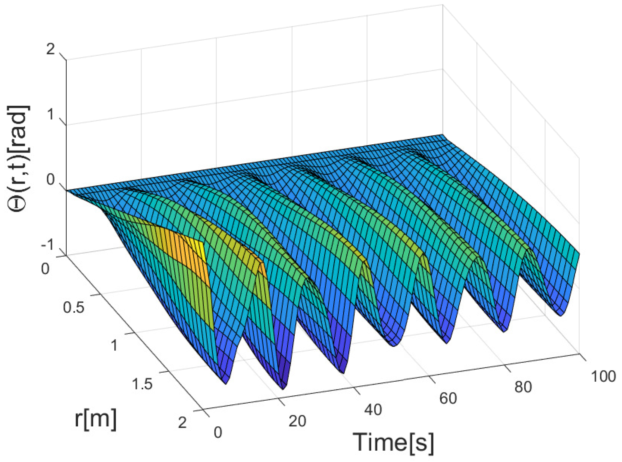
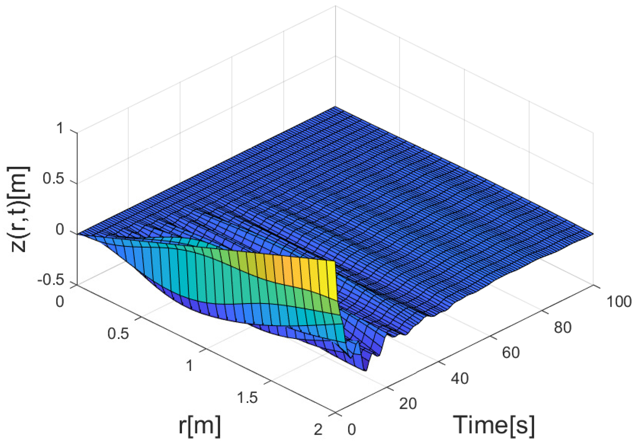
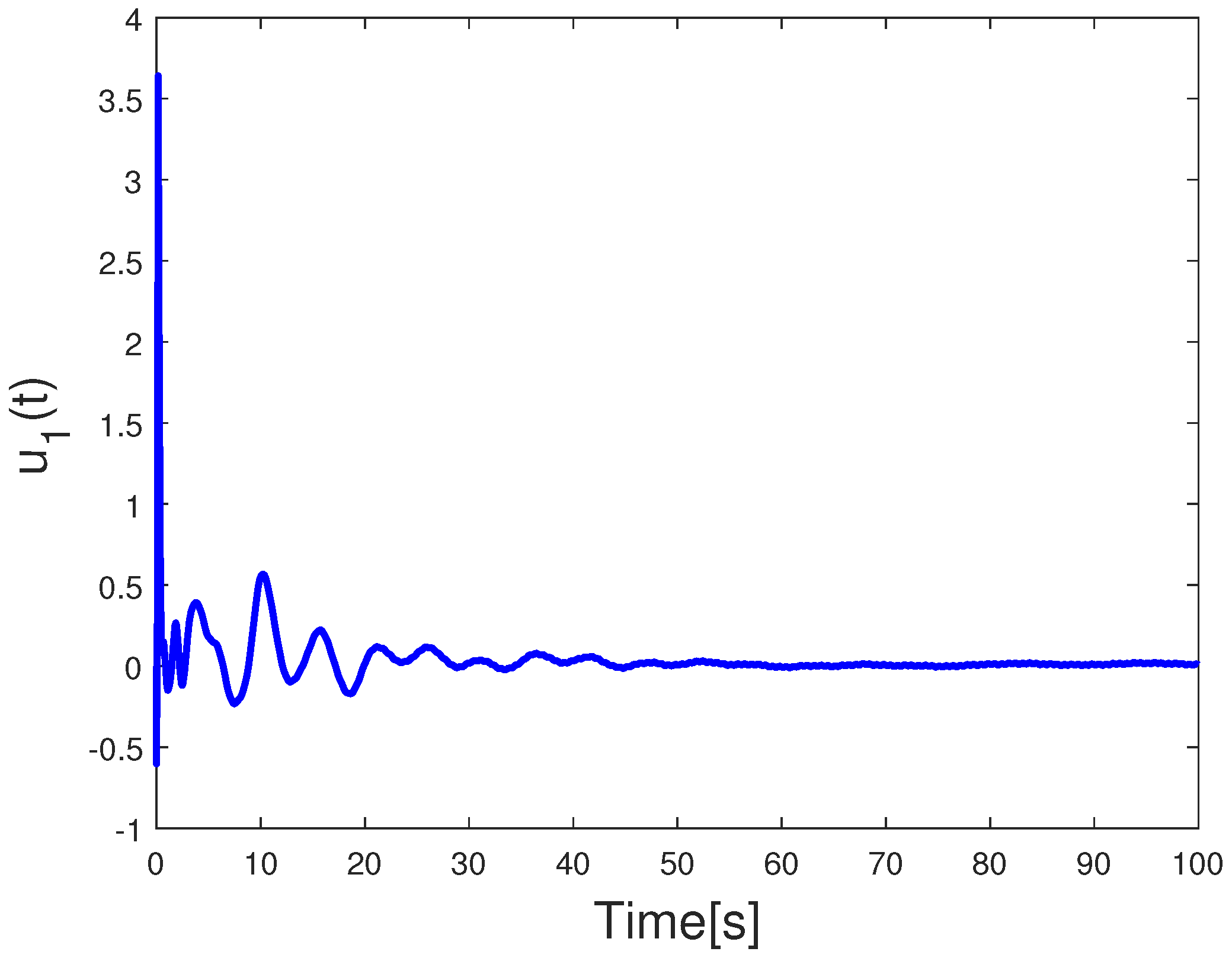
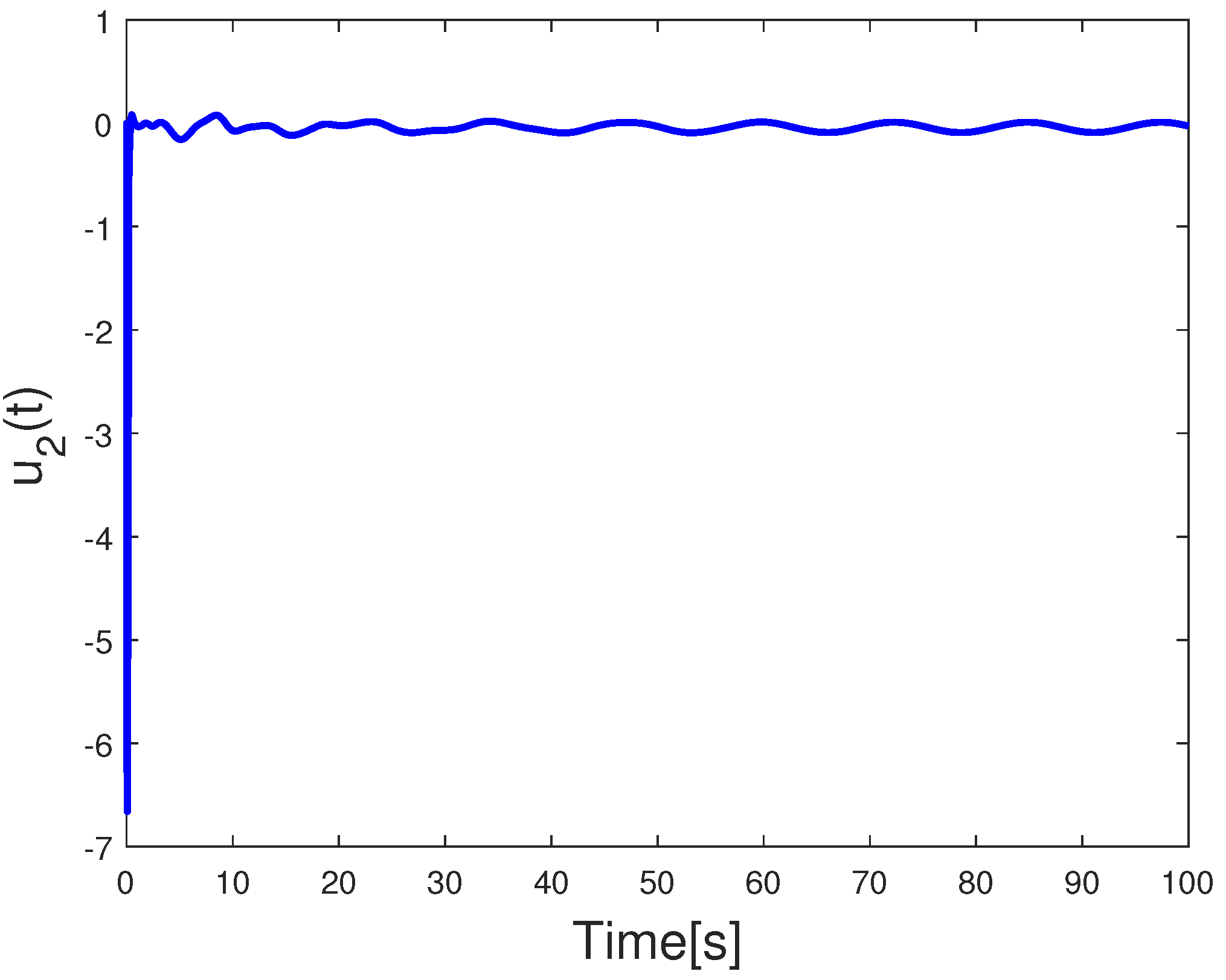
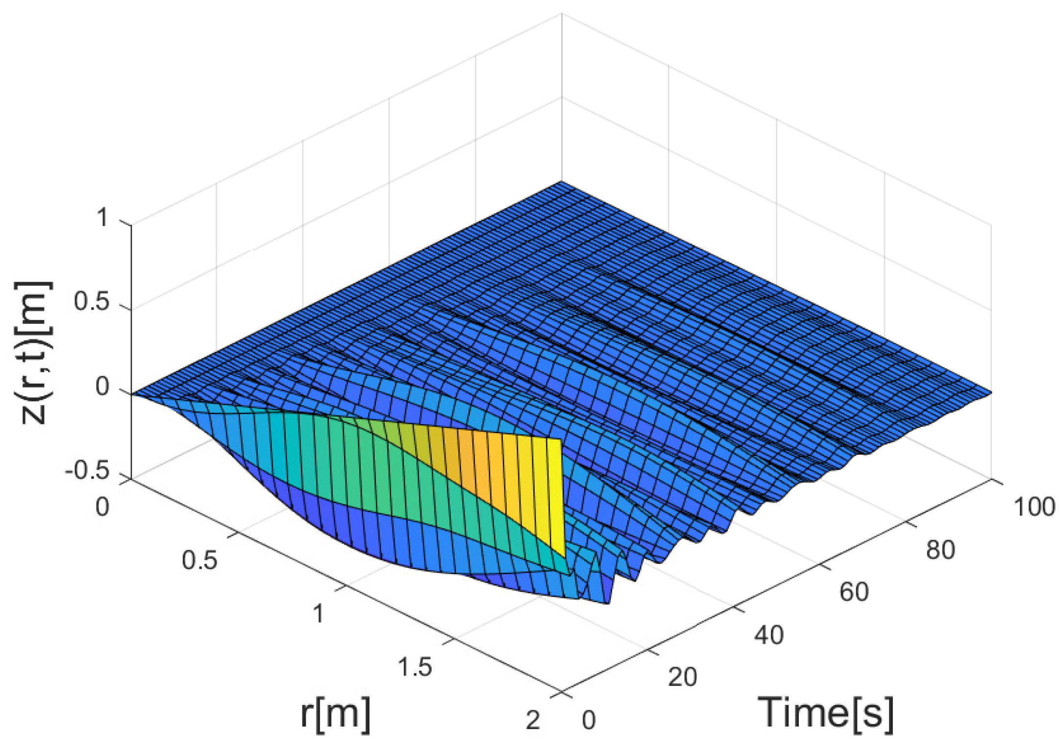
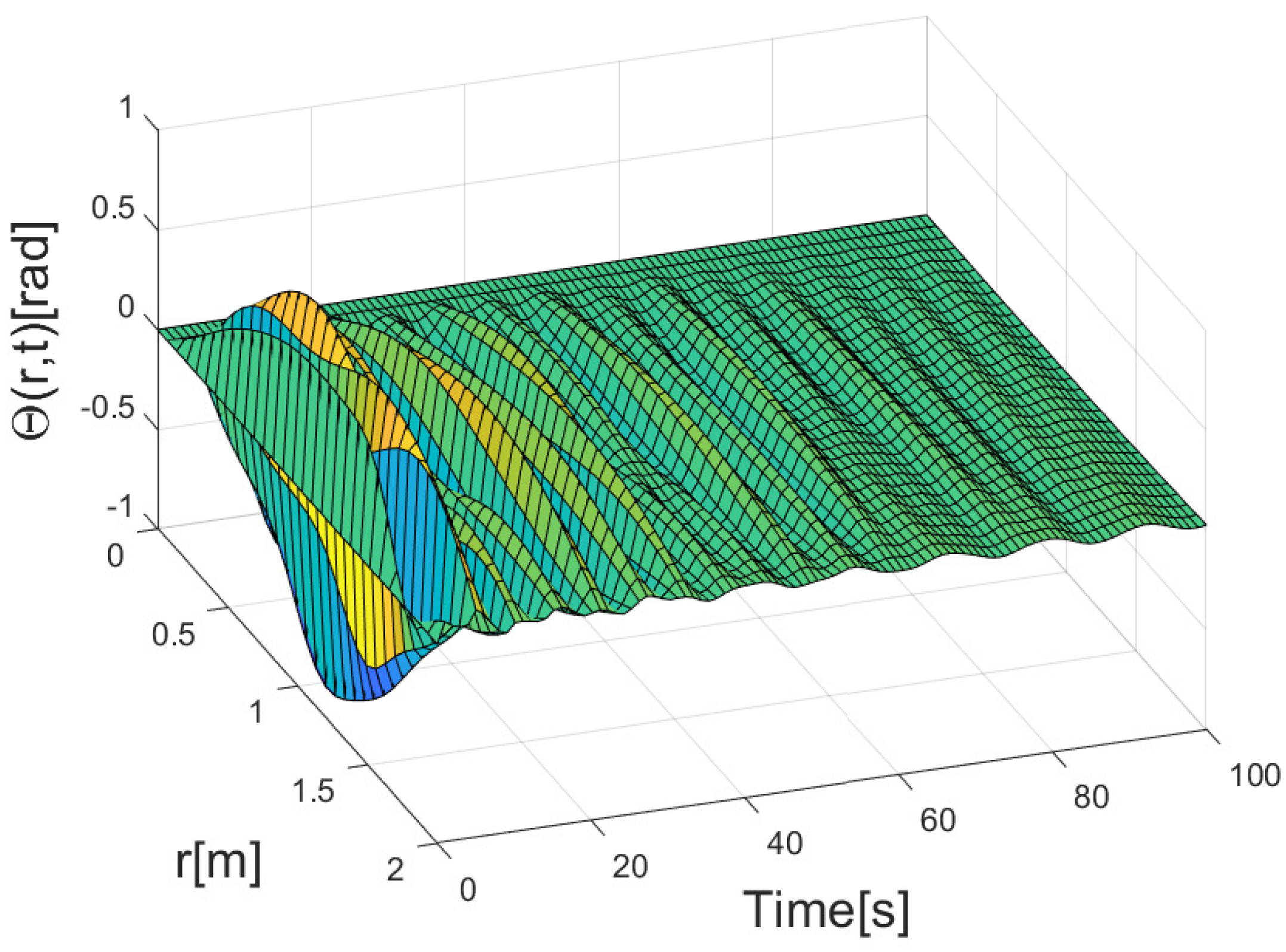
Figure 2 and Figure 3 illustrate the deformation of the flexible wing without control, i.e., when u 1 ( t ) = 0 and u 2 ( t ) = 0 . The maximum displacement can reach approximately 1 m and 1.6 rad, which has significant side effects on the system. Figure 4 and Figure 5 present the stereoscopic representation of flexible wings with proposed control. It can be seen that the 3D direction deflection of the system can be stabilized under control. The parameters selected for the controllers are k 1 = 2 , k 2 = 1 , γ 1 = 0.02 , γ 2 = 5 , μ 11 = μ 12 = 0.15 , and μ 21 = μ 22 = 0.17 . Figure 6 and Figure 7 depict the time-dependent diagrams of the actual inputs. It can be observed that under the influence of inverse hysteresis dynamics (9)–(11), the controller inputs u 1 ( t ) and u 2 ( t ) can converge to zero, effectively avoiding the impact of hysteresis nonlinearity (6)–(8). At the outset, the controller applies relatively large inputs, causing the state variables to rapidly converge near zero. Subsequently, the control inputs are also reduced, and as the state variables converge to zero, the control inputs likewise converge to zero. The initial overshoot is employed to ensure the rapid convergence of the state variables, and the magnitude of the overshoot is kept within the power range of the actuators.
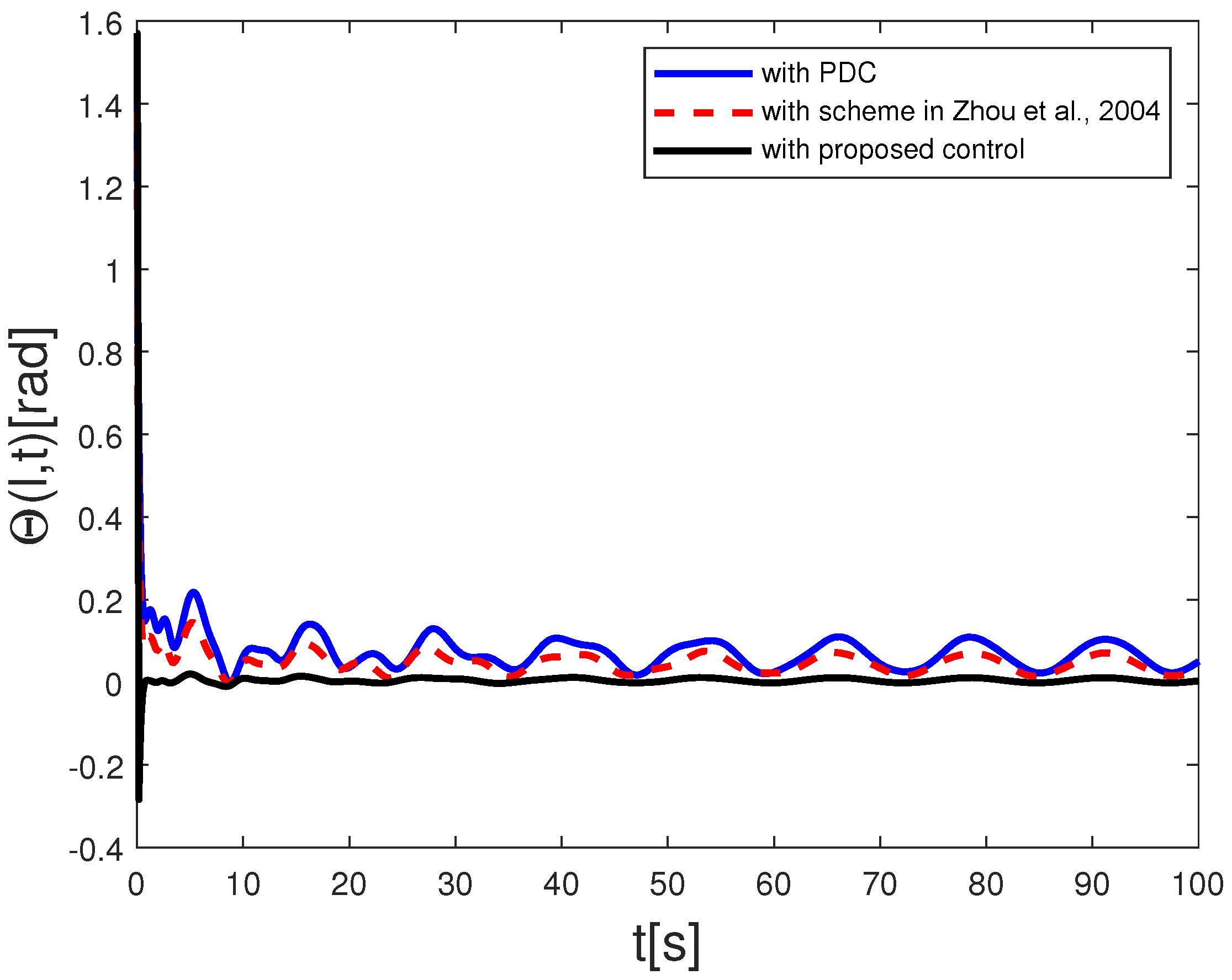
Proportional–derivative controller (PDC) is a type of feedback control system commonly used in engineering and industrial applications. It is a combination of two fundamental control actions: proportional control and derivative control. In this paper, we set a PDC for comparison purposes, which is expressed as τ 1 ( t ) = ψ 1 z ( l , t ) + ψ 2 z ˙ ( l , t ) , and τ 2 ( t ) = ψ 3 Θ ( l , t ) + ψ 4 Θ ˙ ( l , t ) by selecting the control gains as ψ 1 = 5 , ψ 2 = 2.4 , ψ 3 = 60 , and ψ 4 = 0.01 . The PDC method is similar to a model-free approach based on the error and its derivative. The control performance is indicated in Figure 8 and Figure 9. Under the PDC, both displacements converge at a relatively slow speed, and it is difficult for the state to converge near zero. Excessive vibration levels could potentially have an adverse impact on the flight performance of a flapping-wing aircraft. To further validate the effectiveness of the controller proposed in this study, we applied the controller from [33] to the flexible wing system. In [33], a novel adaptive controller has been designed to compensate for a disturbance-like term synthesized from the input hysteresis compensation error and unknown disturbances. Due to its strong robustness, this method has been widely employed in the boundary control for various flexible structures in recent years [19]. However, from Figure 10 and Figure 11, we can observe that the control performance of this controller is relatively poor because the hysteresis compensation operator introduces a compensation error, which increases the disturbance term and may result in slower state convergence. In contrast, the controller proposed in this study eliminates compensation errors, thus addressing this drawback. By comparing the vibration conditions at the top end of the wing based on PDC and the scheme in [33], as shown in Figure 12 and Figure 13, we can conclude that the proposed control method can better guarantee the excellent performance of the flexible wing system. Table 1 gives the performance index of different methods based on the integral time square error (ITSE), and integral time absolute error (ITAE). These performance index reflect the superior control performance of the proposed control method.

5. Conclusions

In this paper, a novel adaptive control strategy based on an inverse hysteresis dynamic model is proposed to address the control problem of a flexible wing system with hysteresis nonlinearity and external disturbances. An adaptive controller is introduced to compensate for unknown external disturbances. Additionally, an inverse hysteresis dynamic model is employed to mitigate the influence of hysteresis nonlinearity on the controller input. Through rigorous theoretical proofs and simulation results, it is demonstrated that the proposed control strategy effectively achieves the stabilization of the flexible wing system and exhibits remarkable performance. Future work will focus on investigating the quantized control of controlled flexible wing systems [34,35].

Author Contributions

Conceptualization, Y.Q. and F.G.; Methodology, Y.Q.; Software, Y.Q.; Validation, F.G. and F.W.; Formal analysis, Y.Q.; Investigation, Y.Q.; Resources, Y.Q. and X.L.; Data curation, Y.Q.; Writing—original draft, Y.Q. and F.G.; Supervision, F.G.; Project administration, F.G.; Funding acquisition, Y.Q., F.W. and Y.H. All authors have read and agreed to the published version of the manuscript.

Funding

This work is supported by the Guangdong Provincial Department of Education Innovation Strong School Program, under Grant 2022ZDZX1031 and 2022KTSCX138, the National Natural Science Foundation of China, under Grant 62203116 and 62103106, and the Dongguan City Social Development Technology Project Key Project, under grant 20231800935882.

Institutional Review Board Statement

Not applicable.

Informed Consent Statement

Not applicable.

Data Availability Statement

Not applicable.

Conflicts of Interest

The authors declare no conflict of interest.

References

  1. Lee, H.; Woo, D.; Yu, S. Virtual reality metaverse system supplementing remote education methods: Based on aircraft maintenance simulation. Appl. Sci. 2022, 12, 2667. [Google Scholar] [CrossRef]
  2. Barzkar, A.; Ghassemi, M. Components of electrical power systems in more and all-electric aircraft: A review. IEEE Trans. Transp. Electrif. 2022, 8, 4037–4053. [Google Scholar] [CrossRef]
  3. Henderson, I.L. Aviation safety regulations for unmanned aircraft operations: Perspectives from users. Transp. Policy 2022, 125, 192–206. [Google Scholar] [CrossRef]
  4. Cinar, G.; Cai, Y.; Bendarkar, M.V.; Burrell, A.I.; Denney, R.K.; Mavris, D.N. System analysis and design space exploration of regional aircraft with electrified powertrains. J. Aircr. 2023, 60, 382–409. [Google Scholar] [CrossRef]
  5. Li, Q.; Ji, A.; Shen, H.; Li, R.; Liu, K.; Zheng, X.; Shen, L.; Han, Q. Experimental study on the wing parameter optimization of flapping-wing aircraft based on the clap-and-fling mechanism. Int. J. Aeronaut. Space Sci. 2022, 23, 265–276. [Google Scholar] [CrossRef]
  6. Smith, M.J.C. Simulating moth wing aerodynamics-towards the development of flapping-wing technology. AIAA J. 1996, 34, 1348–1355. [Google Scholar] [CrossRef]
  7. Jiao, Z.; Wang, L.; Zhao, L.; Jiang, W. Hover flight control of X-shaped flapping wing aircraft considering wing–tail interactions. Aerosp. Sci. Technol. 2021, 116, 106870. [Google Scholar] [CrossRef]
  8. He, W.; Mu, X.; Chen, Y.; He, X.; Yu, Y. Modeling and vibration control of the flapping-wing robotic aircraft with output constraint. J. Sound Vib. 2018, 423, 472–483. [Google Scholar] [CrossRef]
  9. Ozaki, T.; Hamaguchi, K. Improved lift force of a resonant-driven flapping-wing micro aerial vehicle by suppressing wing–body and wing–wing vibration coupling. Extrem. Mech. Lett. 2020, 40, 100867. [Google Scholar] [CrossRef]
  10. He, W.; Meng, T.; He, X.; Sun, C. Iterative learning control for a flapping wing micro aerial vehicle under distributed disturbances. IEEE Trans. Cybern. 2018, 49, 1524–1535. [Google Scholar] [CrossRef]
  11. Zhao, Z.; Liu, Z.; He, W.; Hong, K.-S.; Li, H.-X. Boundary adaptive fault-tolerant control for a flexible Timoshenko arm with backlash-like hysteresis. Automatica 2021, 130, 109690. [Google Scholar] [CrossRef]
  12. Bymes, C.I.; Laukó, I.G.; Gilliam, D.S.; Shubov, V.I. Output regulation for linear distributed parameter systems. IEEE Trans. Autom. Control 2000, 45, 2236–2252. [Google Scholar] [CrossRef]
  13. Zhang, Q.; Song, X.; Song, S.; Stojanovic, V. Finite-Time sliding mode control for singularly perturbed PDE systems. J. Frankl. Inst. 2023, 360, 841–861. [Google Scholar] [CrossRef]
  14. Zhu, G.; Ge, S.S.; Lee, T.H. Simulation studies of tip tracking control of a single-link flexible robot based on a lumped model. Robotica 1999, 17, 71–78. [Google Scholar] [CrossRef]
  15. Ouyang, Y.; He, W.; Li, X. Reinforcement learning control of a single-link flexible robotic manipulator. IET Control. Theory Appl. 2017, 11, 1426–1433. [Google Scholar] [CrossRef]
  16. Liu, S.; Liu, Z.; Li, Y.; He, W. Nonlinear disturbance observer-based direct joint control for manipulation of a flexible payload with output constraints. Int. J. Control 2023, 96, 1377–1388. [Google Scholar] [CrossRef]
  17. Sinclair, B.; McConnell, M.; Green, D.P. Detecting spillover effects: Design and analysis of multilevel experiments. Am. J. Political Sci. 2012, 56, 1055–1069. [Google Scholar] [CrossRef]
  18. Liu, Z.; Han, Z.; Zhao, Z.; He, W. Modeling and adaptive control for a spatial flexible spacecraft with unknown actuator failures. Sci. China Inf. Sci. 2021, 64, 152208. [Google Scholar] [CrossRef]
  19. Zhao, Z.; Liu, Y.; Zou, T.; Hong, K.-S.; Li, H.-X. Robust adaptive fault-tolerant control for a riser-vessel system with input hysteresis and time-varying output constraints. IEEE Trans. Cybern. 2022, 53, 3939–3950. [Google Scholar] [CrossRef]
  20. Li, A.; Liu, M.; Cao, X.; Liu, R. Adaptive quantized sliding mode attitude tracking control for flexible spacecraft with input dead-zone via Takagi-Sugeno fuzzy approach. Inf. Sci. 2022, 587, 746–773. [Google Scholar] [CrossRef]
  21. Zhu, G.; Li, H.; Zhang, X.; Wang, C.; Su, C.-Y.; Hu, J. Adaptive consensus quantized control for a class of high-order nonlinear multi-agent systems with input hysteresis and full state constraints. IEEE/CAA J. Autom. Sin. 2022, 9, 1574–1589. [Google Scholar] [CrossRef]
  22. Cheng, Y.; Niu, B.; Zhao, X.; Zong, G.; Ahmad, A.M. Event-triggered adaptive decentralised control of interconnected nonlinear systems with Bouc-Wen hysteresis input. Int. J. Syst. Sci. 2023, 54, 1275–1288. [Google Scholar] [CrossRef]
  23. Liu, X.; Tong, D.; Chen, Q.; Zhou, W.; Shen, S. Observer-based adaptive funnel dynamic surface control for nonlinear systems with unknown control coefficients and hysteresis input. Neural Process. Lett. 2022, 54, 4681–4710. [Google Scholar] [CrossRef]
  24. Liao, X.; Liu, Z.; Chen, C.L.P.; Zhang, Y. Event-triggered fuzzy control for nonlinear time-delay system with full-state constraints and unknown hysteresis. J. Frankl. Inst. 2022, 359, 1582–1611. [Google Scholar] [CrossRef]
  25. Liu, S.; Zhang, L.; Niu, B.; Zhao, X.; Ahmad, A.M. Adaptive neural finite-time hierarchical sliding mode control of uncertain under-actuated switched nonlinear systems with backlash-like hysteresis. Inf. Sci. 2022, 599, 147–169. [Google Scholar] [CrossRef]
  26. Zhou, J.; Wen, C.; Li, T. Adaptive output feedback control of uncertain nonlinear systems with hysteresis nonlinearity. IEEE Trans. Autom. Control 2012, 57, 2627–2633. [Google Scholar] [CrossRef]
  27. He, W.; Meng, T. Adaptive control of a flexible string system with input hysteresis. IEEE Trans. Control Syst. Technol. 2017, 26, 693–700. [Google Scholar] [CrossRef]
  28. Tao, G.; Kokotovic, P.V. Adaptive control of plants with unknown hystereses. IEEE Trans. Autom. Control 1995, 40, 200–212. [Google Scholar] [CrossRef]
  29. Gao, S.; Zhang, Y.; Liu, J. Adaptive fault-tolerant boundary control for a flexible aircraft wing with input constraints. Aerosp. Sci. Technol. 2019, 90, 34–43. [Google Scholar] [CrossRef]
  30. Ren, Y.; Chen, M.; Liu, J. Bilateral coordinate boundary adaptive control for a helicopter lifting system with backlash-like hysteresis. Sci. China Inf. Sci. 2020, 63, 1–3. [Google Scholar] [CrossRef]
  31. Zhao, Z.; Liu, Y.; Ma, G.; Hong, K.-S.; Li, H.-X. Adaptive Fuzzy Fault-Tolerant Control for a Riser-Vessel System With Unknown Backlash. IEEE Trans. Syst. Man Cybern. Syst. 2023. early access. [Google Scholar] [CrossRef]
  32. Zhao, Z.; Tan, Z.; Liu, Z.; Efe, M.O.; Ahn, C.K. Adaptive Inverse Compensation Fault-Tolerant Control for a Flexible Manipulator with Unknown Dead-zone and Actuator Faults. IEEE Trans. Ind. Electron. 2023, 70, 12698–12707. [Google Scholar] [CrossRef]
  33. Zhou, J.; Wen, C.; Zhang, Y. Adaptive backstepping control of a class of uncertain nonlinear systems with unknown backlash-like hysteresis. IEEE Trans. Autom. Control 2004, 49, 1751–1759. [Google Scholar] [CrossRef]
  34. Zhao, Z.; Liu, Y.; Cai, S.; Li, Z.; Wang, Y.; Hong, K.-S.; Li, H.-X. Adaptive Quantized Control of Flexible Manipulators Subject to Unknown Dead Zones. IEEE Trans. Syst. Man Cybern. Syst. 2023. early access. [Google Scholar] [CrossRef]
  35. Zhao, Z.; Zhang, J.; Liu, Z.; He, W.; Hong, K.-S. Adaptive quantized fault-tolerant control of a 2-DOF helicopter system with actuator fault and unknown dead zone. Automatica 2023, 148, 110792. [Google Scholar] [CrossRef]
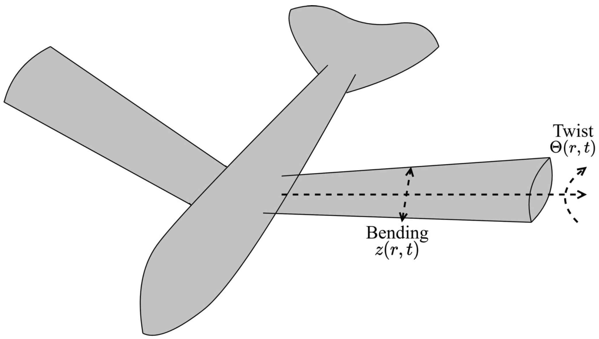
Figure 1. Flapping-wing robotic aircraft.
Mathematics 11 03841 g001
Figure 2. Bending deformations of the wing in the uncontrolled state.
Mathematics 11 03841 g002
Figure 3. Twist deformation of the wing in the uncontrolled state.
Mathematics 11 03841 g003
Figure 4. Bending deformation of the wing under the proposed control.
Mathematics 11 03841 g004
Figure 5. Twist deformation of the wing under the proposed control.
Mathematics 11 03841 g005
Figure 6. Actual input u 1 ( t ) of flexible wing.
Mathematics 11 03841 g006
Figure 7. Actual input u 2 ( t ) of flexible wing.
Mathematics 11 03841 g007
Figure 8. Bending deformation of the wing under PDC.
Mathematics 11 03841 g008
Figure 9. Twist deformation of the wing under PDC.
Mathematics 11 03841 g009
Figure 10. Bending deformation of the wing under the scheme in [33].
Mathematics 11 03841 g010
Figure 11. Twist deformation of the wing under the scheme in [33].
Mathematics 11 03841 g011
Figure 12. Bending deformation with different control approaches (with PFC, scheme in [33], and proposed control).
Mathematics 11 03841 g012
Figure 13. Twist deformation with different control approaches (with PFC, scheme in [33], and proposed control).
Mathematics 11 03841 g013
Table 1. Comparison of different approaches in simulation, with ITSE and ITAE as performance index.
IndexBending Deformation
MethodsPDCScheme in [33]Proposed Control
ITSE-16.86446.38935.0516
ITAE-227.1647114.4611105.0891
IndexTwist Deformation
MethodsPDCScheme in [33]Proposed Control
ITSE-25.843611.48972.2290
ITAE-326.4926215.910425.2367
Disclaimer/Publisher’s Note: The statements, opinions and data contained in all publications are solely those of the individual author(s) and contributor(s) and not of MDPI and/or the editor(s). MDPI and/or the editor(s) disclaim responsibility for any injury to people or property resulting from any ideas, methods, instructions or products referred to in the content.