Article

An Optimized Control Method of Soft-Switching and No Backflow Power for LLC Resonant-Type Dual-Active-Bridge DC-DC Converters

School of Electrical Engineering, China University of Mining and Technology, Xuzhou 221116, China
*
Author to whom correspondence should be addressed.
Mathematics 2023, 11(2), 287; https://doi.org/10.3390/math11020287
Submission received: 18 November 2022 / Revised: 20 December 2022 / Accepted: 30 December 2022 / Published: 5 January 2023
(This article belongs to the Special Issue Modeling and Simulation for the Electrical Power System)

Abstract

:
The LLC-type resonant dual-active-bridge (LLC-DAB) DC-DC converter with a high voltage gain, high power density, and low backflow power has attracted increasing attention in recent years. However, its soft-switching and backflow power problems are still not solved, so the improvements to these problems are studied in this paper. Based on the dual phase shift (DPS) modulation method, the operating characteristics are analyzed, and a soft-switching and no backflow power modulation curve is established based on the voltage-current time-domain characteristics. On this basis, a soft-switching and no backflow power optimized control method based on DPS modulation is proposed to achieve soft-switching operation and eliminate backflow power. Due to the complex time-domain characteristics of the resonant tank voltage and current, the relationship between the phase shift ratios is fitted and optimized with this method based on the soft-switching and no backflow power characteristic curve, and the optimized results of the phase shift ratio under different operating conditions are obtained. The simulation results indicate that the soft-switching operation of the LLC-DAB converter can be achieved with the optimized control method proposed in this paper, and the backflow power is effectively eliminated.

1. Introduction

Dual Active Bridge (DAB) DC-DC converter features good electrical isolation, fast dynamic response and high power density [1], which is widely applications in electric vehicle charging piles, distributed energy storage and renewable energy generation. However, the conventional DAB DC-DC converter suffers from the problems of backflow power and hard-switching [2,3,4]. The conduction loss due to backflow power and the switching loss due to hard-switching are not negligible. Therefore, the elimination of backflow power and the realization of soft-witching have become the key to reducing the operating loss of the DAB converter.
In recent years, the exploration of the elimination of the backflow power and the realization of the soft-switching operation of the DAB converter has attracted a lot of research work from many domestic and foreign scholars. For modulation control, phase shift modulation is usually adopted in DAB converters. Based on the original Single-Phase-Shift (SPS) modulation method [5], many scholars have proposed Extended-Phase-Shift (EPS) modulation [6], Dual-Phase-Shift (DPS) modulation [7], and Triple- Phase-Shift (TPS) modulation [8] methods. Although the reduction of backflow power and the reduction of current stress can be achieved by these modulation methods, it is still difficult to realize soft switching. The optimal phase shift ratio corresponding to the minimum return power or to achieve soft-switching was obtained in [9,10,11,12], and optimal control methods for no backflow power or soft-switching were proposed, but neither of these methods is optimized for both backflow power and soft-switching.
The optimization and change of topology are other options to eliminate the backflow power and realize soft-switching, in addition to improving the modulation method of the DAB converter. The LLC-Type resonant dual active bridge (LLC-DAB) DC-DC converter has gained a lot of attention due to its advantages, such as high voltage gain and high power density [13,14,15].
In [13], an LLC-type DAB bidirectional converter with a reduced number of switches was studied, which can provide full load range zero voltage switching (ZVS) for eight main switches and wide load range ZVS for four auxiliary switches. An LLC-DAB DC-DC converter with an integrated core and shared rectifier was proposed in [14] to achieve fast output voltage regulation and ZVS for all switches and zero current switching (ZCS) operation of the rectifier. A novel hybrid LLC resonant DAB linear DC-DC converter was proposed in [15] and was regarded as a bus converter that achieves soft-switching operation and constant output voltage gain in open-loop conditions with a light load and closed-loop conditions with a heavy load. A closed-loop control strategy for high-power LLC DC-DC converters was proposed in [16], which can achieve zero-voltage switching over the entire output range under closed-loop conditions. However, when the operating frequency of the system is higher than the resonant frequency, if there is a large change in the input and output of the converter, the loop gain will also change sharply, which will reduce the overall stability of the system. Scholars have optimized the output design and analyzed the loss and stability of different circuit structures [17,18,19]. In [17], an improved model predictive control method using optimized voltage vectors and switching sequences is proposed, which divides the voltage space vector into six sectors and subdivides the sectors using finite sets, and optimized the sequence between sampling periods to improve the current quality and significantly reduce the switching losses. A multilevel inverter based on bridge modular switched capacitor (BMSC) circuits is proposed in [18] to reduce the power loss by optimizing the multilevel voltage phase, and each stage is controlled independently to improve the system stability. In [19], an energy hub output control is designed based on the features of energy networks as well as the containment and consensus algorithms, which achieves accurate sharing of the electricity and heat load power.
Since DPS modulation has a higher control degree of freedom than SPS modulation and is simpler than TPS modulation, in this paper, the problems of realization of soft-switching and no backflow power of LLC-DAB DC-DC converter are studied based on DPS modulation. Based on the voltage and current time-domain characteristics, and with consideration of multiple solutions for phase shift ratio at the same voltage gain, a soft-switching and no back power optimized control method for LLC-DAB converter is proposed to reduce the backflow power based on the soft-switching operation of all switches.

2. Principle of LLC-DAB DC-DC Converter

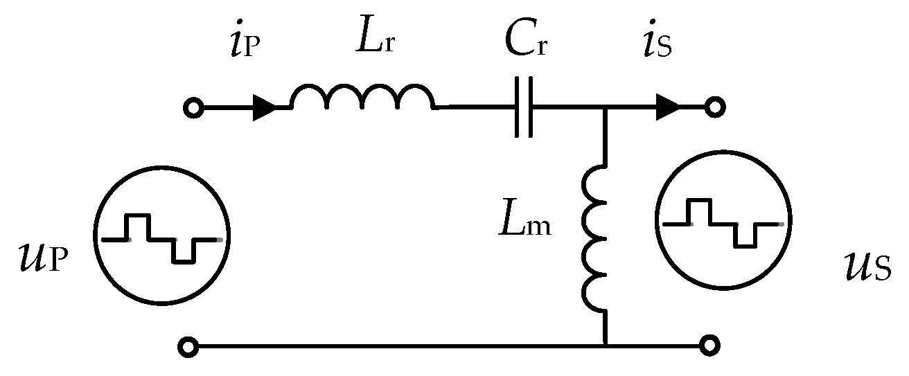
2.1. Principle of Power Transmission

As shown in Figure 1, the difference between the LLC-DAB DC-DC converter and the conventional DAB DC-DC converter is the replacement of the filter inductor with an LLC resonant tank. The notations used to describe the topology and the characteristics of the converter are presented at the end of the paper. The resonant tank consists of two filter inductors and a filter capacitor. The leakage inductance and the excitation inductance of the transformer are converted to the primary side of the converter and become a part of the Lm. To simplify the operation, the inductance of both filter inductors Lr and Lm default to L.
In the LLC-DAB DC-DC converter, the two H-bridges are coupled with the high-frequency transformer through the LLC resonant tank. Each of them can be regarded as an inverter unit to generate high-frequency AC voltage square waves. In the power transfer process, the inductor is the key component for bidirectional power transfer, which completes the charging and discharging in one switching period. The high-frequency transformer plays the role of electromagnetic isolation and voltage matching.

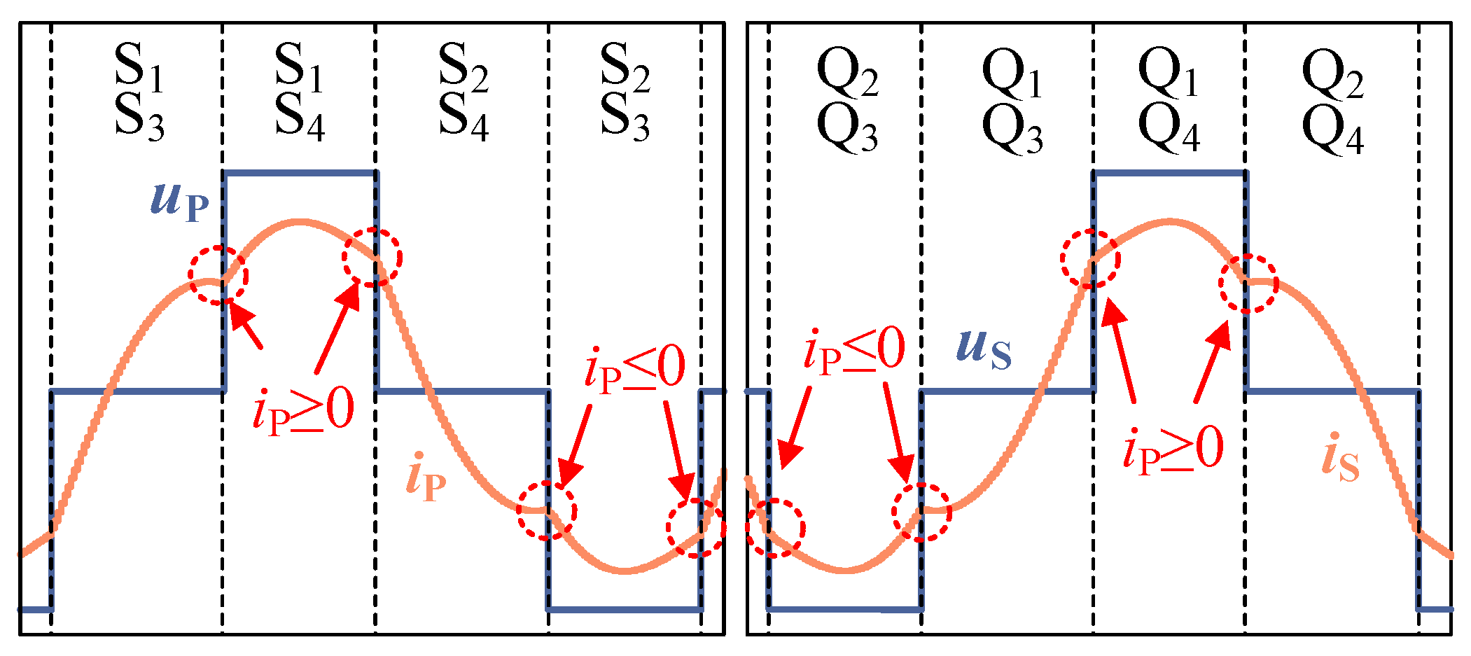
2.2. Principle of LLC-DAB Operation with DPS Modulation

The LLC-DAB DC-DC converter can be represented by the equivalent circuit model shown in Figure 2. The two AC voltage sources, uP and uS, are connected through an LLC resonant tank. The magnitude and direction of the power transmitted by the converter are determined by the amplitude, phase and frequency of the voltages on both sides of the LLC resonant tank. Power is transmitted from the P side to the S side for forward power flow when the phase angle difference between the voltages of the two sides is positive. On the contrary, power is transferred from the S side to the P side when the phase angle difference is negative. The power of DAB is always transferred from the phase-leading side to the phase-lagging side.
In addition, all drive signals of DAB are square wave signals with a 50% duty cycle, and the signals of the upper and lower two switching tubes of each bridge arm are complementary. There are two control variables in the DPS modulation, which are d1 and d. The corresponding dT is the phase shift time between the symmetry axes of uP and uS, and d1T is the phase shift time between the drive signals S1 and S4. Figure 3 shows the switching sequences of each switch and the voltage waveforms of each side of the LLC-DAB converter with DPS modulation, where uP and uS are both three-level AC square wave voltages with the same frequency.
Since the initial phases of uP and uS have no influence on the operation characteristics, the middle moment of the high level of uS is regarded as the origin of time to simplify the derivation. The existence of a resonant tank makes the time domain analysis process complicated; thus, this paper adopted the vector method to analyze and derive the input and output characteristics of the LLC-DAB DC-DC converter with forward power flow. Therefore, the relationship between the voltage and current at each frequency of the resonant tank can be expressed as
[ I ˙ P _ n I ˙ S _ n ] = [ j n ω C ( n 2 ω 2 L C 1 ) j n ω C ( n 2 ω 2 L C 1 ) j n ω C ( n 2 ω 2 L C 1 ) j ( 2 n 2 ω 2 L C 1 ) ( n 3 ω 3 L 2 C n ω L ) ] [ U ˙ P _ n U ˙ S _ n ]
where ω = 2πfs. When the LLC-DAB converter is operated with the modulation shown in Figure 3, the time-domain expressions for uP and uS are shown in the following equations:
u P ( t ) = { 0 ( 1 4 d 4 T < t 1 4 d + 2 d 1 4 T ) U in ( 1 4 d + 2 d 1 4 T < t 3 4 d 2 d 1 4 T ) 0 ( 3 4 d 2 d 1 4 T < t 3 4 d + 2 d 1 4 T ) U in ( 3 4 d + 2 d 1 4 T < t 5 4 d 2 d 1 4 T ) 0 ( 5 4 d 2 d 1 4 T < t 5 4 d 4 T )
u S ( t ) = { 0 ( 1 4 T < t 1 + 2 d 1 4 T ) N U o ( 1 + 2 d 1 4 T < t 3 2 d 1 4 T ) 0 ( 3 2 d 1 4 T < t 3 + 2 d 1 4 T ) N U o ( 3 + 2 d 1 4 T < t 5 2 d 1 4 T ) 0 ( 5 2 d 1 4 T < t 5 4 T )
Since uP and uS are shown by (2) and (3) to be periodic signals, they can be approximated by the Fourier series. Then, the vector expressions of uP and uS at each frequency can be obtained by phasor analysis method, as
U ˙ P _ n = ( 1 ) n 1 2 2 2 U in n π × cos ( n π d 1 ) × [ cos ( 2 π n d ) + j sin ( 2 π n d ) ]
U ˙ S _ n = ( 1 ) n 1 2 2 2 N U o n π cos ( n π d 1 )
Substituting (4) and (5) into (1), the expression of the currents on both sides of the resonant tank can be derived as
I ˙ P _ n = ( 1 ) n 1 2 2 2 U in ω C cos ( n π d 1 ) ( n 2 ω 2 L C 1 ) π × { sin ( 2 π n d ) + j [ k cos ( 2 π n d ) ] }
I ˙ S _ n = ( 1 ) n 1 2 2 2 U in cos ( n π d 1 ) n 2 ω L ( n 2 ω 2 L C 1 ) π × { n 2 ω 2 L C sin ( 2 π n d ) j [ n 2 ω 2 L C cos ( 2 π n d ) + k 2 k n 2 ω 2 L C ] }
where k = NUo/Uin. The expressions of iP(t) and is(t) can be obtained with the inverse Fourier transform of (6) and (7).
i P _ n ( t ) = 4 U in ω C π n = 1 , 3 , 5 ( 1 ) n 1 2 cos ( n π d 1 ) ( n 2 ω 2 L C 1 ) × { sin ( 2 π n d ) cos ( n ω t ) [ k cos ( 2 π n d ) ] sin ( n ω t ) }
i S _ n ( t ) = 4 U in ω L π n = 1 , 3 , 5 ( 1 ) n 1 2 cos ( n π d 1 ) n 2 ( n 2 ω 2 L C 1 ) × { n 2 ω 2 L C sin ( 2 π n d ) cos ( n ω t ) + [ n 2 ω 2 L C cos ( 2 π n d ) + k 2 k n 2 ω 2 L C ] sin ( n ω t ) }
Assuming that the converter transmits power without losses, the transmitted power of the converter can be obtained via the superposition of the transmitted power of each harmonic, and the active power can be represented by an expression with infinite terms. Since the power error caused by the neglect of higher-order harmonics in the resonant converter is small, only the fundamental wave content is considered to analyze the active power transmitted by the converter. Then the average transmitted power of the converter can be expressed as
P = 8 N U in U o ω C π 2 ( ω 2 L C 1 ) cos 2 ( π d 1 ) sin ( 2 π d )

3. Operating Characteristics of LLC-DAB DC-DC Converter

In this section, firstly, the analytical expression of the voltage gain of the LLC-DAB converter with DPS modulation is derived based on the mathematical expression of the converter. Then the theoretical connection between phase shift ratio to total harmonic distortion (THDi) is discussed, and the design curves of no backflow power and soft-switching with DPS modulation are established, which lay a foundation for the research of optimal control methods.

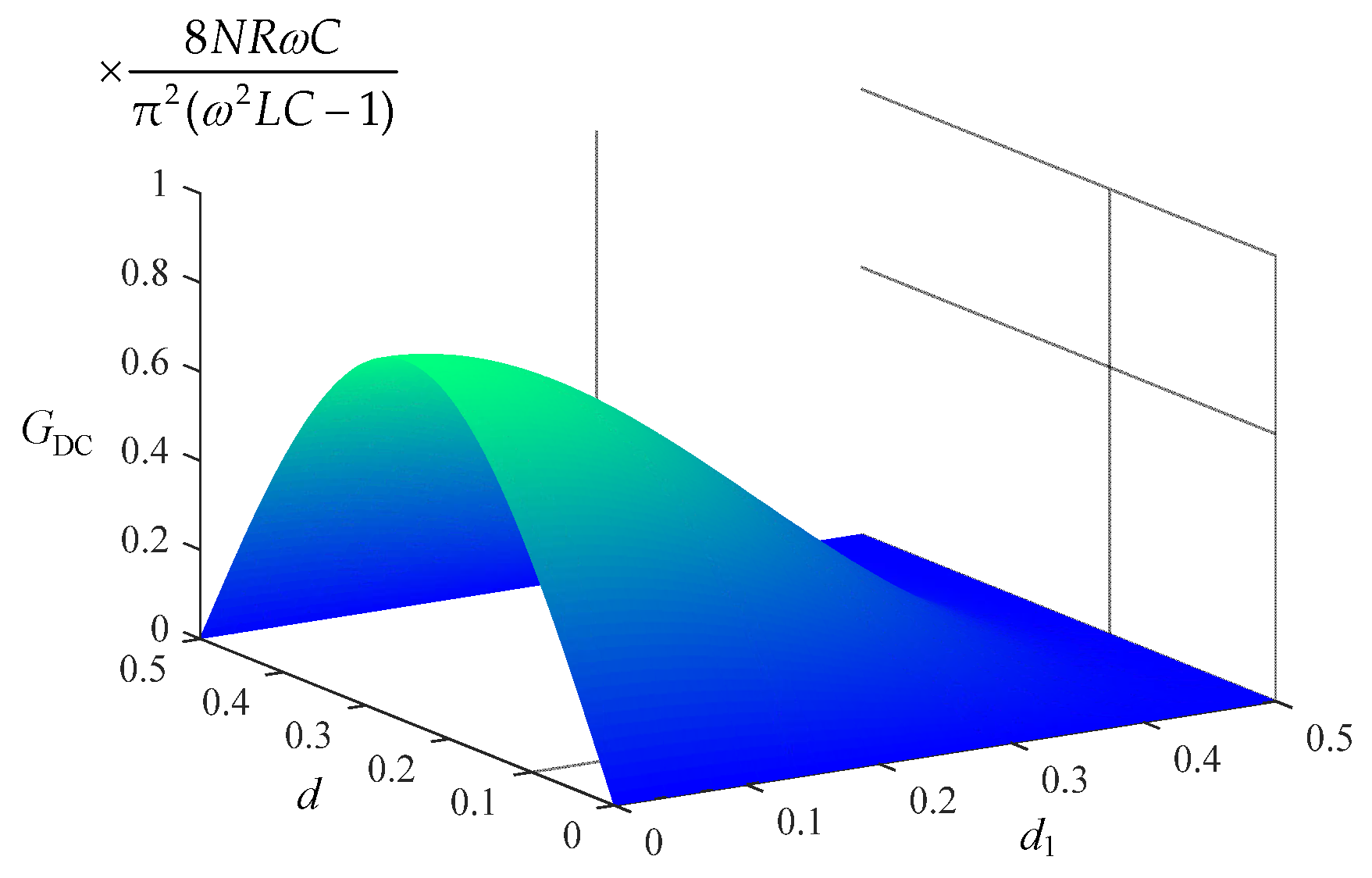
3.1. Voltage Gain Characteristics

The DC voltage gain of the LLC-DAB converter is defined as GDC = Uo/Uin, and the load is assumed to be resistive load R. The output voltage Uo and the converter DC voltage gain GDC can be deduced from (10) as
U o = 8 N U in R ω C π 2 ( ω 2 L C 1 ) cos 2 ( π d 1 ) sin ( 2 π d )
G DC = 8 N R ω C π 2 ( ω 2 L C 1 ) cos 2 ( π d 1 ) sin ( 2 π d )
To directly observe the relationship between voltage gain and phase shift ratios, the other items can be extracted, so the voltage gain of the LLC-DAB converter with different phase shift ratios d1 and d is shown in Figure 4. If the external phase shift ratio d is determined, the voltage gain decreases as the internal phase shift ratio d1 increases. If the internal phase shift ratio d1 is determined, as the external phase shift ratio d increases, the voltage gain increases first, decreases symmetrically, and reaches the maximum value at d = 0.25.

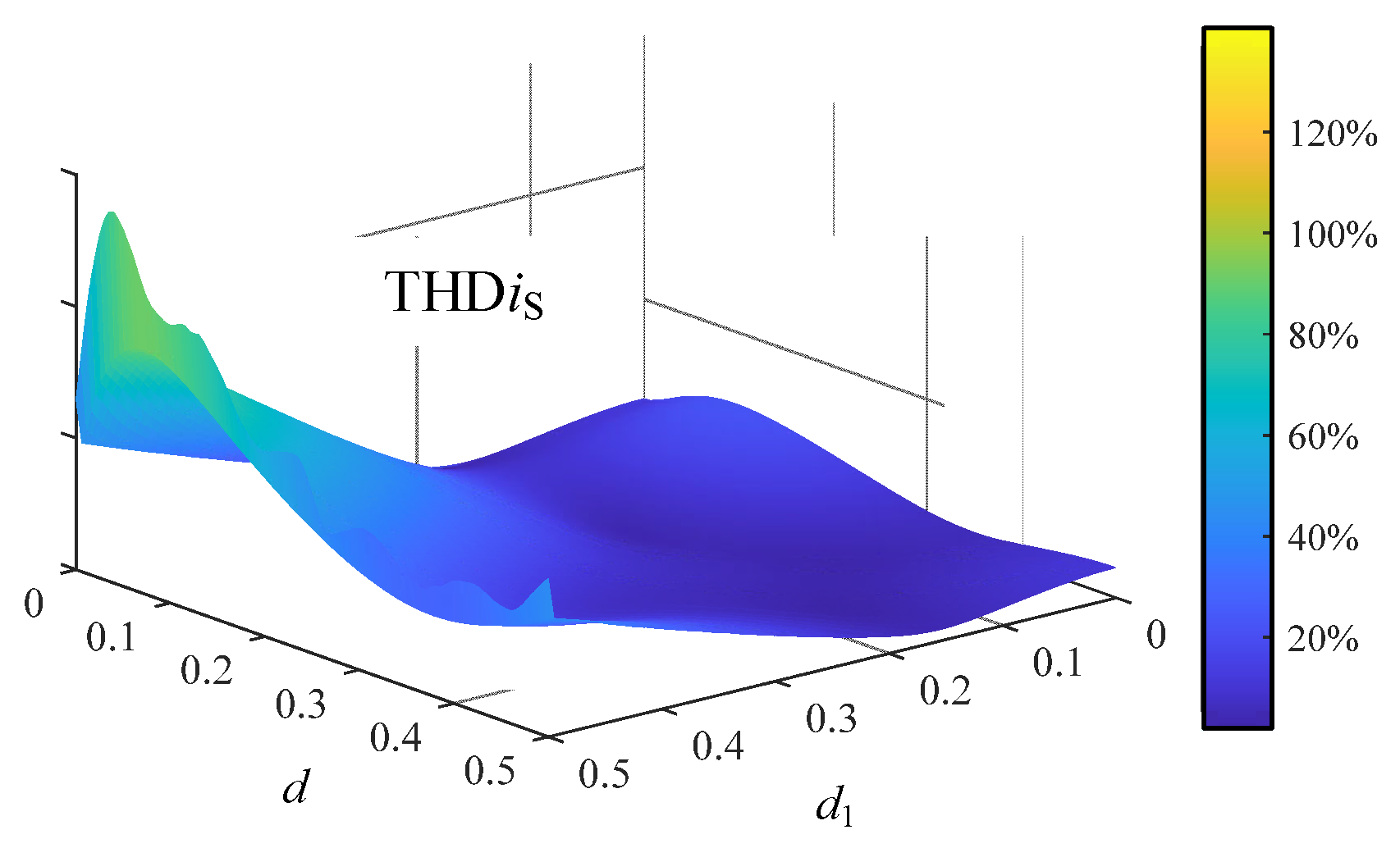
3.2. Current Gain Characteristics

To quantify and analyze the current harmonic content in the LLC resonant tank, THDi is introduced. After the neglect of the harmonics above the 5th harmonic, the THDi can be expressed as
THD i P = n = 3 , 5 , 7 ( I P _ n / I P _ 1 ) 2 × 100 %
THD i S = n = 3 , 5 , 7 ( I S _ n / I S _ 1 ) 2 × 100 %
Substituting (13) and (14) into (6) and (7), respectively, the THDi at the P side and S side can be obtained with different k. Assuming k = 1, the 3D surface of THDiP with different phase shift ratios is shown in Figure 5. When d is determined, THDiP tends to increase as d1 increases. When d1 is determined, and d is close to 0, THDiP increases sharply and eventually rises to infinity at d = 0. The 3D surface of THDis with different phase shift ratios is shown in Figure 6. When d is determined, THDis also tends to increase as d1 increases. When d1 is determined, there is no significant change in THDis. It can be indicated from Figure 5 and Figure 6 that THDi varies considerably with different phase shift ratios d1 and d and is so large in some modulation regions that it is not negligible. Therefore, it is difficult to accurately calculate the instantaneous values of the currents iP(t) and iS(t) if only the fundamental components are considered.

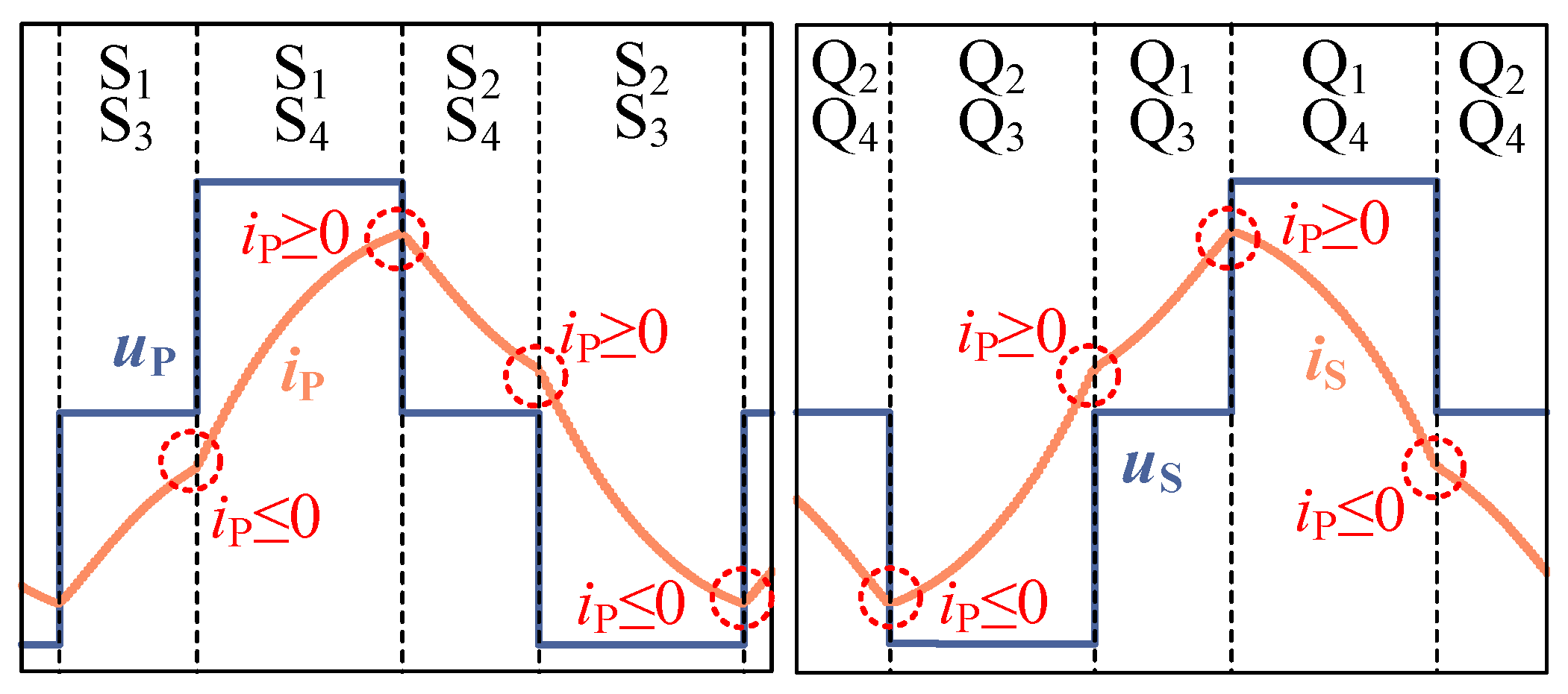
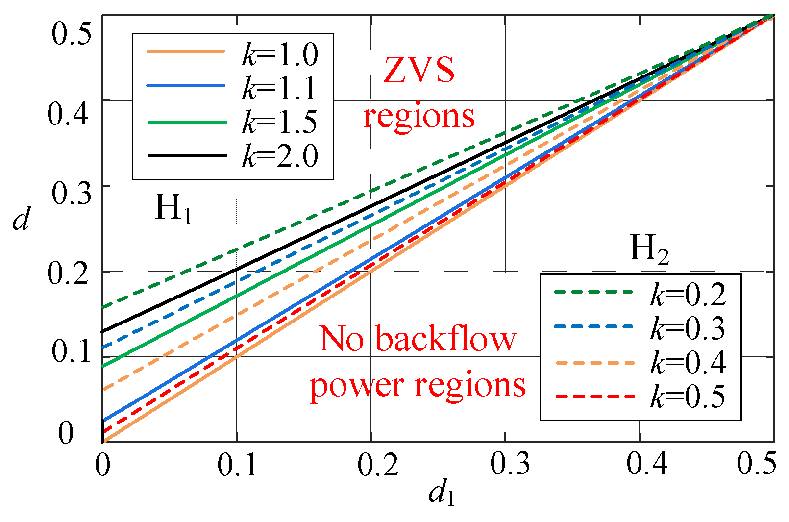
3.3. Backflow Power and Soft-Switching Characteristics

Since the first half period and the second half period of the LLC-DAB converter operation state are positive-negative symmetric, only half of the period is necessary to analyze the backflow power and soft-switching characteristics. The existence of the LLC resonant tank makes the current waveform approximate a sine wave, so the converter can be realized without backflow power operation when the voltage and current waveforms at the P side and S side always maintain the same polarity and the main voltage and current waveforms are shown in Figure 7. Thus, the constraints of no backflow power of the converter with DPS modulation can be derived, as shown in (15)–(18). The constraints of no backflow operation on the primary side are indicated by (15) and (16), corresponding to iP(t0) and iP(t1) in Figure 7, respectively. (17) and (18) indicate the conditions of no backflow operation on the subside side, corresponding to iP(t2) and iP(t3) in Figure 8, respectively.
n = 1 , 3 , 5 ( 1 ) n 1 2 cos ( n π d 1 ) ( n 2 ω 2 L C 1 ) × { sin ( 2 π n d ) cos [ 2 π ( 3 4 d + 2 d 1 4 ) ] [ k cos ( 2 π n d ) ] sin [ 2 π ( 3 4 d + 2 d 1 4 ) ] } 0
n = 1 , 3 , 5 ( 1 ) n 1 2 cos ( n π d 1 ) ( n 2 ω 2 L C 1 ) × { sin ( 2 π n d ) cos [ 2 π ( 5 4 d 2 d 1 4 ) ] [ k cos ( 2 π n d ) ] sin [ 2 π ( 5 4 d 2 d 1 4 ) ] } 0
n = 1 , 3 , 5 ( 1 ) n 1 2 cos ( n π d 1 ) ( n 2 ω 2 L C 1 ) × { sin ( 2 π n d ) cos [ 2 π ( 3 + 2 d 1 4 ) ] [ k cos ( 2 π n d ) ] sin [ 2 π ( 3 + 2 d 1 4 ) ] } 0
n = 1 , 3 , 5 ( 1 ) n 1 2 cos ( n π d 1 ) ( n 2 ω 2 L C 1 ) × { sin ( 2 π n d ) cos [ 2 π ( 5 4 d 2 d 1 4 ) ] [ k cos ( 2 π n d ) ] sin [ 2 π ( 5 4 d 2 d 1 4 ) ] } 0
The elimination of backflow power facilitates the reduction of the conduction losses of the converter. To reduce the switching losses, soft-switching technology is one of the effective measures, which is essential to reduce the voltage or current of the switch to zero before the switching action occurs. For DAB converters, the soft-switching is generally realized by forcing the current through its anti-parallel diode before the switch is conducted. The main voltage and current waveforms of the converter to realize soft-switching are shown in Figure 8. Based on the condition of zero-voltage conduction and the time-domain characteristics of voltage and current at the P side and S side, it can be obtained that the conditions of zero-voltage conduction for the four switches of the H1 bridge are (19) and (20), corresponding to iP(t0) and iP(t1) in Figure 8, respectively. The conditions for the four switches of the H2 bridge to realize zero-voltage conduction are (21) and (22), which correspond to iP(t2) and iP(t3) in Figure 8, respectively.
n = 1 , 3 , 5 ( 1 ) n 1 2 cos ( n π d 1 ) ( n 2 ω 2 L C 1 ) × { sin ( 2 π n d ) cos [ 2 π ( 3 4 d + 2 d 1 4 ) ] [ k cos ( 2 π n d ) ] sin [ 2 π ( 3 4 d + 2 d 1 4 ) ] } 0
n = 1 , 3 , 5 ( 1 ) n 1 2 cos ( n π d 1 ) ( n 2 ω 2 L C 1 ) ×   { sin ( 2 π n d ) cos [ 2 π ( 5 4 d 2 d 1 4 ) ] [ k cos ( 2 π n d ) ] sin [ 2 π ( 5 4 d 2 d 1 4 ) ] } 0
n = 1 , 3 , 5 ( 1 ) n 1 2 cos ( n π d 1 ) ( n 2 ω 2 L C 1 ) × { sin ( 2 π n d ) cos [ 2 π ( 3 + 2 d 1 4 ) ] [ k cos ( 2 π n d ) ] sin [ 2 π ( 3 + 2 d 1 4 ) ] } 0
n = 1 , 3 , 5 ( 1 ) n 1 2 cos ( n π d 1 ) ( n 2 ω 2 L C 1 ) × { sin ( 2 π n d ) cos [ 2 π ( 5 2 d 1 4 ) ] [ k cos ( 2 π n d ) ] sin [ 2 π ( 5 2 d 1 4 ) ] } 0

4. Soft-Switching and No Backflow Power Optimized Control Method with DPS Modulation
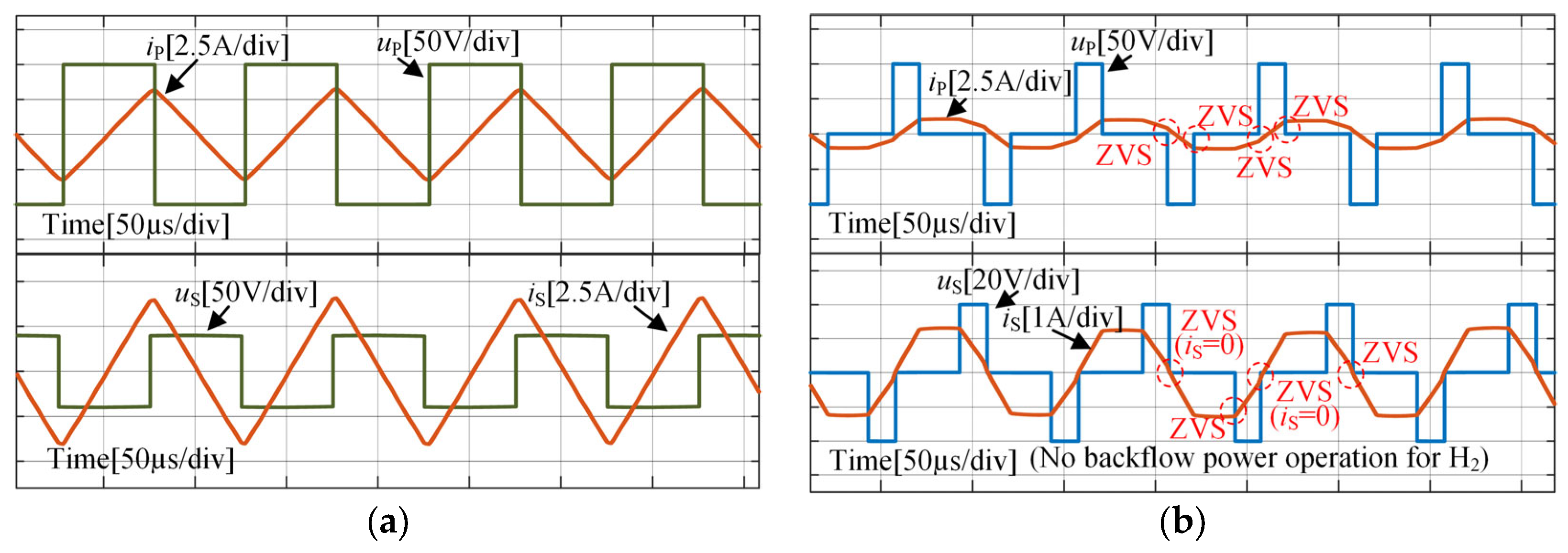
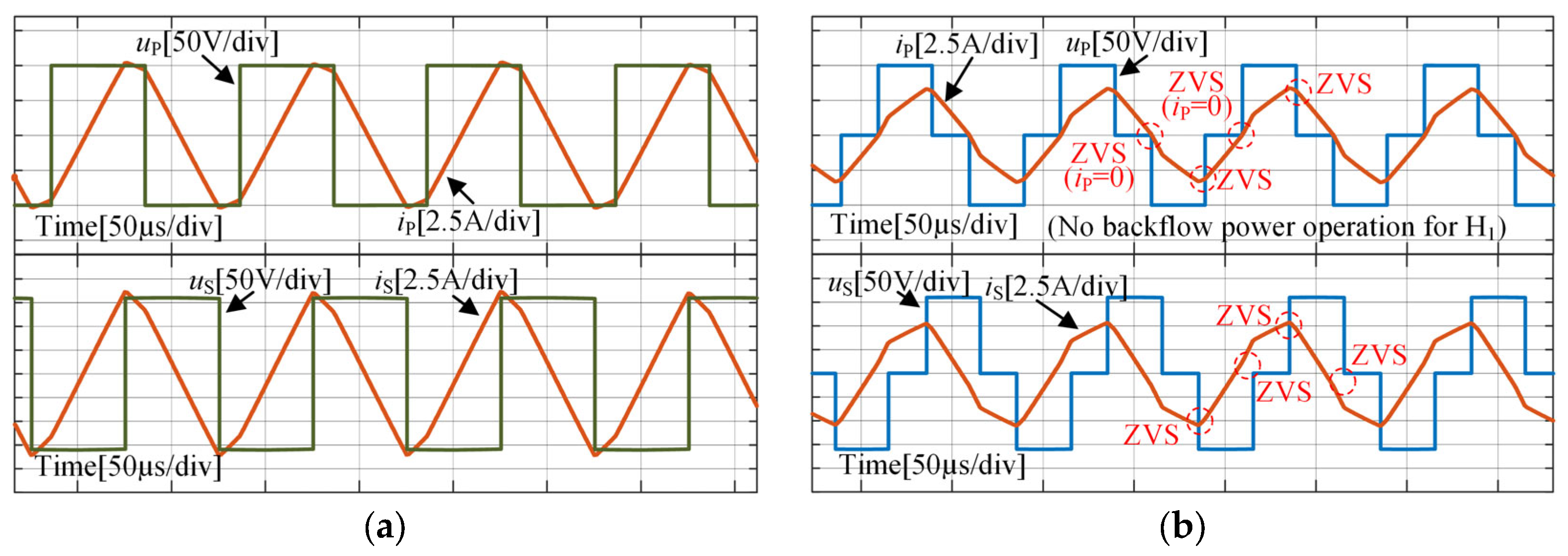
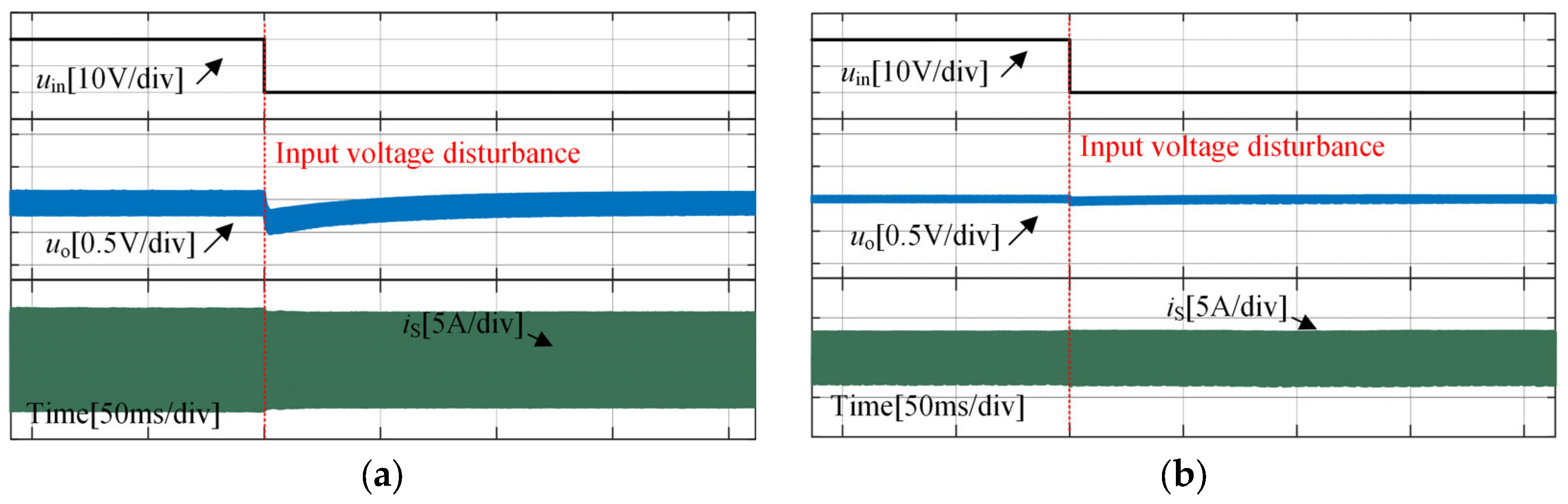
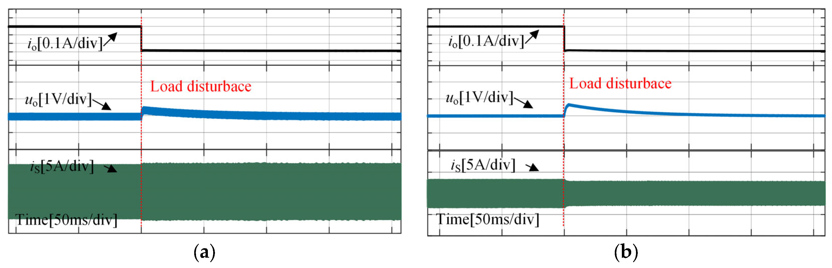
Substituting (8) and (9) into (15)–(22) and taking the intersection of the constraint conditions of the P side and S side, respectively. The condition to achieve soft-switching and no backflow power on the P side can be simplified as (23), and the condition of realizing soft-switching and no backflow power on the S side can be simplified as (24). Both sides are in the critical state of no backflow power and soft-switching.
n = 1 , 3 , 5 ( 1 ) n 1 2 cos ( n π d 1 ) ( n 2 ω 2 L C 1 ) × { sin ( 2 π n d ) cos [ 2 π ( 3 4 d + 2 d 1 4 ) ] [ k cos ( 2 π n d ) ] sin [ 2 π ( 3 4 d + 2 d 1 4 ) ] } = 0
n = 1 , 3 , 5 ( 1 ) n 1 2 cos ( n π d 1 ) ( n 2 ω 2 L C 1 ) × { sin ( 2 π n d ) cos [ 2 π ( 5 2 d 1 4 ) ] [ k cos ( 2 π n d ) ] sin [ 2 π ( 5 2 d 1 4 ) ] } = 0
The no backflow power and soft-switching modulation curves of the LLC-DAB converter with different k, calculated based on the system parameters in Table 1, are shown in Figure 9. The solid line in Figure 9 is the modulation curve of the H1 bridge, which represents the phase shift ratio obtained from the solution of (23). These phase shift ratios of the converter can realize the soft-switching and no backflow power operation of the H1 bridge, which is also the critical soft-switching and critical no backflow power operation state of the H1 bridge. The dashed line is the modulation curve of the H2 bridge, representing the shifted phase derived from the solution of (24), which realizes the soft-switching and no backflow power operation of the H2 bridge, and also the critical soft-switching and critical no backflow power operation state of the H2 bridge. The upper side of the modulation curve corresponds to the soft-switching operation design region for each of the respective full bridges. According to Figure 9, it can be seen that when k < 1, the four switches of the H1 bridge will realize soft-switching operation in the full modulation region, but no backflow power operation of the H1 bridge cannot be realized. For k ≥ 1, the soft-switching operation region is gradually reduced as the increment of k. For k ≤ 0.5, the soft-switching operation area of the H2 bridge gradually expands with the increase of k. For k > 0.5, the soft-switching operation of the four switches of the H2 bridge can be realized in the full modulation region, but the no backflow power operation of the H2 bridge cannot be realized. Therefore, to ensure that the converter features a sufficient range of optimal operating conditions, the transformer ratio should be determined according to the actual situation, and k should be reasonably designed. The expressions are complicated since the time domain expressions for the currents iP and is contain many harmonic components. To simplify the calculation in the control process, the soft-switching and no backflow power design curves of the H1 bridge and H2 bridge with different k are fitted, respectively. And the conditions for zero voltage condition and critical no backflow power of H1 and H2 bridges can be obtained, as shown in (25) and (26).
d 1 = k d 0.5 k + 0.5 + 0.25 0.25 k 0.5 k + 0.5
d 1 = ω 2 L C d ω 2 L C ( k + 0.5 ) 0.5 k + ω 2 L C ( 0.5 k 0.25 ) 0.25 k ω 2 L C ( k + 0.5 ) 0.5 k
However, the modulation relation of the H2 bridge obtained from the fitting is related to the hardware parameters, which require a huge computation and is not convenient for application. Therefore, in consideration of 2ω2LC >> 1 in most cases, simplify (25) and (26) as
d 1 = { k d 0.5 k + 0.5 + 0.25 0.25 k 0.5 k + 0.5 k 0.5 d k + 0.5 + 0.5 k 0.25 k + 0.5 k > 0.5
In this paper, an optimized control method of soft-switching and no backflow power with DPS modulation for LLC-DAB converter is proposed based on the above calculation, and its control block diagram is shown in Figure 10. The proportional-integral controller is adopted to adjust d so that the output voltage follows the reference voltage. k is calculated based on the output and input voltages to determine the corresponding optimal relationship for the phase shift ratio and to calculate d1 at this moment. By synchronizing d and d1, the soft-switching operation of all switches in the converter can be realized. Hence, the backflow power can be minimized or even eliminated to meet the design requirements of optimizing the operation state of the converter.

5. Verification

To verify the optimized control of soft-switching and no backflow power of the LLC-DAB converter proposed in this paper, a simulation model of the LLC-DAB converter with DPS modulation is established by Matlab/Simulink, and the system parameters are shown in Table 1. Steady-state experiments were carried out in three groups based on the output voltage and k with the same input voltage conditions, corresponding to output voltages of 20 V, 50 V, and 100 V, respectively. In addition, the SPS modulation method is widely used in practice because of its simplicity and high reliability. Therefore, SPS control is adopted in the experiment, which is compared with the control method proposed in this paper, and the optimization effect of the converter operation state is verified.
The steady-state waveforms in LLC resonant tank with two control methods for three different conditions as shown in Figure 11, Figure 12 and Figure 13. The soft-switching operation of eight switches and no backflow power operation of the H1 bridge is realized with k = 1 and k = 1.6. The no backflow power operation of the H2 bridge is realized with k = 0.4. The backflow power of the full bridge on both sides cannot be eliminated in three conditions with SPS modulation, which results in high current stress on the switch. It leads to the converter operation loss larger and also affects the electrical life of the switches. Therefore, it is proved in the steady-state simulation that the soft-switching operation of all switches and the minimization of backflow power can be realized via the optimized control.
To test the transient response characteristics of the system after a change in the operating state, the transient response waveforms of the output voltage and transformer current with the two control methods mentioned above are given when the input voltage Uin changes from 100 V to 80 V, as shown in Figure 14. The transient response waveforms of load current, output voltage and transformer current when the load R changes from 50 Ω to 70 Ω with the two control methods are shown in Figure 15. It can be seen that the voltage fluctuations with the proposed control method and SPS modulation method are small, and their responses are very fast for both input voltage disturbance and load disturbance. The simulation test results show that the control method proposed in this paper features a good transient response to the disturbance.

6. Conclusions

Aiming at reducing the power loss caused by hard switching and backflow power of LLC-DAB converter, in this paper, the input-output characteristics of LLC-DAB converter are analyzed, and the relationship between the phase shift ratio and the converter voltage gain as well as that between the phase shift ratio and THDi is derived. The soft-switching and no backflow power design curves of the LLC-DAB converter with DPS modulation are established, and thus a soft-switching and no backflow power optimized control method based on DPS modulation is proposed. The control method enables the soft-switching operation of the 8 switches of the converter based on the relationship between the internal and external phase shift ratios derived from the fitting design curves and eliminates the return power to the maximum extent. Finally, the validity and effectiveness of the control method are verified by simulation and experimental results.

Author Contributions

Conceptualization, M.L. and D.Y.; methodology, Z.L. and Z.W.; software, Y.Z.; validation, Z.L., Z.W. and Y.Z.; formal analysis, Z.L. and Z.W.; data curation, M.L.; writing—original draft preparation, Z.L.; writing—review and editing, R.X.; supervision, R.X. and D.Y.; project administration, D.Y. All authors have read and agreed to the published version of the manuscript.

Funding

This research was funded by the 2022 Postgraduate Research & Practice Innovation Program of Jiangsu Province, grant number KYCX22_2544, and the National Nature Science Foundation of China, 51977208.

Data Availability Statement

Not applicable.

Conflicts of Interest

The authors declare no conflict of interest.

Nomenclature

Lr, LmFilter inductor
CrFilter capacitor
N:1Turn ratio of the transformer
Uin, UoDC input voltage and DC output voltage
Cdc1, Cdc2DC filter capacitor
RResistance of the load
uP, uSAC output voltages of the H1 bridge and H2 bridge
iP, iSCurrents of the inductor Lr and the primary side of the transformer
dOuter phase shift ratio
d1Inner phase shift ratio
TSwitching period
fsSwitching frequency
ωResonant frequency
PTransmission power
GDCDC voltage gain
THDiP, THDiSTotal harmonic distortion of iP and iS

References

  1. Inoue, S.; Akagi, H. A bi-directional isolated DC/DC converter as a core circuit of the next-generation medium-voltage power conversion system. In Proceedings of the 2006 37th IEEE Power Electronics Specialists Conference, Jeju, Republic of Korea, 18–22 June 2006. [Google Scholar] [CrossRef]
  2. Akagi, H.; Kinouchi, S.I.; Miyazaki, Y. Bidirectional isolated dual-active-bridge (DAB) DC-DC converters using 1.2-kV 400-A SiC-MOSFET dual modules. CPSS Trans. Power Electron. Appl. 2016, 1, 33–40. [Google Scholar] [CrossRef]
  3. Oswald, N.; Anthony, P.; Mcneill, N.; Stark, B.H. An Experimental Investigation of the Tradeoff between Switching Losses and EMI Generation with Hard-Switched All-Si, Si-SiC, and All-SiC Device Combinations. IEEE Trans. Power Electron. 2014, 29, 2393–2407. [Google Scholar] [CrossRef]
  4. Du, Y.; Lukic, S.; Jacobson, B.; Huang, A. Review of High Power Isolated Bi-directional DC-DC Converters for PHEV/EV DC Charging Infrastructure. In Proceedings of the 2011 IEEE Energy Conversion Congress and Exposition, Phoenix, AZ, USA, 31 October 2011. [Google Scholar] [CrossRef]
  5. Song, W.; Hou, N.; Wu, M. Virtual Direct Power Control Scheme of Dual Active Bridge DC–DC Converters for Fast Dynamic Response. IEEE Trans. Power Electron. 2017, 27, 1750–1759. [Google Scholar] [CrossRef]
  6. Zhao, B.; Yu, Q.; Sun, W. Extended-Phase-Shift Control of Isolated Bidirectional DC–DC Converter for Power Distribution in Microgrid. IEEE Trans. Power Electron. 2012, 27, 4667–4680. [Google Scholar] [CrossRef]
  7. Liu, X.; Zhu, Z.Q.; Stone, D.A.; Foster, M.P.; Chu, W.Q.; Urquhart, I.; Greenough, J. Novel Dual Phase Shift Control with Bi-directional Inner phase shifts for Dual Active Bridge Converter Having Low Surge Current and Stable Power Control. IEEE Trans. Power Electron. 2016, 32, 4095–4106. [Google Scholar] [CrossRef]
  8. Wu, K.; Wdesilva, C.; Gdunford, W. Stability Analysis of Isolated Bidirectional Dual Active Full-Bridge DC–DC Converter with Triple Phase-Shift Control. IEEE Trans. Power Electron. 2012, 27, 2007–2017. [Google Scholar] [CrossRef]
  9. Wen, H.; Zheng, L. Minimum Backflow Power Control of Bidirectional Isolated DC-DC Converters. In Proceedings of the 2018 IEEE International Conference on Power Electronics, Drives and Energy Systems, Chennai, India, 18–21 December 2018. [Google Scholar] [CrossRef]
  10. Chu, Y.; Wang, S. Bi-directional isolated DC-DC converters with reactive power loss reduction for electric vehicle and grid support applications. In Proceedings of the 2012 IEEE Transportation Electrification Conference and Expo, Dearborn, MI, USA, 18–20 June 2012. [Google Scholar] [CrossRef]
  11. Shi, H.; Wen, H.; Hu, Y.; Jiang, L. Reactive Power Minimization in Bidirectional DC–DC Converters Using a Unified-Phasor-Based Particle Swarm Optimization. IEEE Trans. Power Electron. 2018, 33, 10990–11006. [Google Scholar] [CrossRef]
  12. Garcia-Bediaga, A.; Villar, I.; Rujas, A.; Mir, L. DAB modulation schema with extended ZVS region for applications with wide input/output voltage. IET Power Electron. 2018, 11, 2109–2116. [Google Scholar] [CrossRef]
  13. Liao, Y.; Xu, G.; Peng, T.; Sun, Y.; Liu, D.; Yang, Y.; Su, M. An LLC-DAB Bidirectional DCX Converter with Wide Load Range ZVS and Reduced Switch Count. IEEE Trans. Power Electron. 2022, 37, 2250–2263. [Google Scholar] [CrossRef]
  14. Wang, M.; Pan, S.; Zha, X.; Gong, J.; Lin, W.; Gao, J.; Deng, Q. Hybrid Control Strategy for an Integrated DAB-LLC-DCX DC-DC Converter to Achieve Full-Power-Range Zero-Voltage Switching. IEEE Trans. Power Electron. 2021, 36, 14383–14397. [Google Scholar] [CrossRef]
  15. Liu, C.; Liu, H.; Cai, G.; Cui, S.; Liu, H.; Yao, H. Novel Hybrid LLC Resonant and DAB Linear DC-DC Converter: Average Model and Experimental Verification. IEEE Trans. Ind. Electron. 2017, 64, 6970–6978. [Google Scholar] [CrossRef]
  16. Gopiyani, A.; Patel, V. A closed-loop control of high power LLC Resonant Converter for DC-DC applications. In Proceedings of the 2011 Nirma University International Conference on Engineering, Ahmedabad, India, 8–10 December 2011. [Google Scholar] [CrossRef]
  17. Liu, C.; Xing, X.; Du, C.; Zhang, B.; Zhang, C.; Blaabjerg, F. An Improved Model Predictive Control Method Using Optimized Voltage Vectors for Vienna Rectifier with Fixed Switching Frequency. IEEE Trans. Power Electron. 2023, 38, 358–371. [Google Scholar] [CrossRef]
  18. He, L.; Cheng, C. A Bridge Modular Switched-Capacitor-Based Multilevel Inverter with Optimized SPWM Control Method and Enhanced Power-Decoupling Ability. IEEE Trans. Ind. Electron. 2018, 65, 6140–6149. [Google Scholar] [CrossRef]
  19. Zhang, N.; Sun, Q.; Yang, L.; Li, Y. Event-Triggered Distributed Hybrid Control Scheme for the Integrated Energy System. IEEE Trans. Ind. Inform. 2022, 18, 835–846. [Google Scholar] [CrossRef]
Figure 1. Topology of an LLC-DAB DC-DC converter.
Mathematics 11 00287 g001
Figure 2. Equivalent model of an LLC-DAB DC-DC converter.
Mathematics 11 00287 g002
Figure 3. Operation waveforms of DPS modulation method.
Mathematics 11 00287 g003
Figure 4. The output voltage gain of LLC-DAB converters with DPS modulation.
Mathematics 11 00287 g004
Figure 5. The relationship between phase shift ratio and THDiP with DPS modulation.
Mathematics 11 00287 g005
Figure 6. The relationship between phase shift ratio and THDiS with DPS modulation.
Mathematics 11 00287 g006
Figure 7. Main voltage and current waveforms of no backflow power.
Mathematics 11 00287 g007
Figure 8. Main voltage and current waveforms of soft-switching.
Mathematics 11 00287 g008
Figure 9. Design curves of no backflow power and soft-switching with DPS modulation.
Mathematics 11 00287 g009
Figure 10. The optimized control of soft-switching and no backflow power.
Mathematics 11 00287 g010
Figure 11. Steady-state waveforms with two control methods in LCL resonant tank when Uin = 20 V and k = 0.4. (a) SPS modulation; (b) Soft-switching and no backflow power control.
Mathematics 11 00287 g011
Figure 12. Steady-state waveforms with two control methods in LCL resonant tank when Uin = 50 V and k = 1. (a) SPS modulation; (b) Soft-switching and no backflow power control.
Mathematics 11 00287 g012
Figure 13. Steady-state waveforms with two control methods in LCL resonant tank when Uin = 80 V and k = 1.6. (a) SPS modulation; (b) Soft-switching and no backflow power control.
Mathematics 11 00287 g013
Figure 14. Transient response waveforms with two control methods when input voltage changed from 100 to 80 V. (a) SPS modulation; (b) Soft-switching and no backflow power control.
Mathematics 11 00287 g014
Figure 15. Transient response waveforms with two control methods when load changed from 50 Ω to 70 Ω. (a) SPS modulation; (b) Soft-switching and no backflow power control.
Mathematics 11 00287 g015
Table 1. Main system parameters.
SymbolValueSymbolValue
Uo(1)20 Vk(1)0.4
Uo(2)50 Vk(2)1
Uo(3)80 Vk(3)1.6
Uin100 VR50 Ω
L1.15 mHN2
C12.2 μFfs10 kHz
Disclaimer/Publisher’s Note: The statements, opinions and data contained in all publications are solely those of the individual author(s) and contributor(s) and not of MDPI and/or the editor(s). MDPI and/or the editor(s) disclaim responsibility for any injury to people or property resulting from any ideas, methods, instructions or products referred to in the content.

