Article

New Results on Finite-Time Synchronization of Complex-Valued BAM Neural Networks with Time Delays by the Quadratic Analysis Approach

1
School of Science, Hubei University of Technology, Wuhan 430068, China
2
School of Mathematics, Hunan University, Changsha 410082, China
*
Author to whom correspondence should be addressed.
Mathematics 2023, 11(6), 1378; https://doi.org/10.3390/math11061378
Submission received: 13 February 2023 / Revised: 7 March 2023 / Accepted: 10 March 2023 / Published: 12 March 2023

Abstract

:
In this paper, we are interested in the finite-time synchronization of complex-valued BAM neural networks with time delays. Without applying Lyapunov–Krasovskii functional theory, finite-time convergence theorem, graph-theoretic method, the theory of complex functions or the integral inequality method, by using the quadratic analysis approach, inequality techniques and designing two classes of novel controllers, two novel sufficient conditions are achieved to guarantee finite-time synchronization between the master system and the slave system. The quadratic analysis method used in our paper is a different study approach of finite-time synchronization from those in existing papers. Therefore the controllers designed in our paper are fully novel.

1. Introduction

Along with the development of information technology, complex-valued neural networks (CVNNs) as the generalization of real-valued neural networks (RVNNs) have attracted increasing attention due to the wide range of applications in some systems involving remote sensing, optoelectronics, antenna design, radar imaging, artificial neural information processing and optimization problems. As a result of the superior complex-valued features of their states, connection weights and activation functions, many problems which RVNNs fail to address can be perfectly solved by CVNNs, such as the XOR problem, and speed and direction in the wing profile model. Therefore, it is important and meaningful to investigate the dynamical behaviors of CVNNs. To date, the global asymptotic/exponential synchronization (GAS/GES) of CVNNs has been widely studied, for example, see [1,2,3,4,5,6,7,8,9,10,11,12]. In addition, synchronization in a finite-time occupies a non-negligible position in dynamic behaviors. In recent years, many meaningful results of finite-time synchronization (FTS) for CVNNs have been extensively explored, for example, see [1,13,14,15,16,17,18,19,20,21,22,23,24,25,26,27,28,29,30,31,32,33].
Paper [13] aimed at FTS for a class of delayed drive–response CVNNs while applying inequality techniques and designing two different kinds of exponential controllers of time variables. In [14], the authors studied the FTS of delayed complex-valued recurrent neural networks (CVRNNs) with discontinuous activation functions and nonidentical parameters by means of designing a sliding surface involving integral structure and a discontinuous control. In [15], in relation to the finite-time synchronization problem of master–slave complex-valued memristive neural networks (CVMNNs), based on the finite-time stability (FTST) criterion with impulsive effects, they considered a new Lyapunov function (LF) and designed a decentralized FTS controller. In [16], focused on dealing with the time delay of the coupled systems, the authors discussed the FTS of complex-valued coupled chaotic systems (CVCCS) with bounded non-identical perturbations and discontinuous activations.
Furthermore, in [1], the FTS between two delayed diffusive CVNNs with discontinuous activations was obtained by establishing a novel negative exponent controller. In [17], because of the needs of some practical projects, the synchronization issue of CVMNNs which contain reaction–diffusion terms and Markovian jump parameters was investigated. Furthermore, in the work of [18], the authors paid attention to the FTS for a class of fully CVNNs with or without delays via proposing intermittent control schemes but without utilizing the ordinary separation technique. In [19], through decomposing the CVRNNs into real and imaginary parts, the FTS of CVRNNs with discontinuous activations and time-varying delays was analyzed. In [20], relying on the Lyapunov method and graph-theoretic method, they focused on researching the FTS issue of fractional-order complex-valued dynamical networks with multiple weights, which is different from other papers. Furthermore, in [21], the authors proposed a nonseparation approach to consider the problem of FTS for fully complex-valued dynamical networks.
To date, the criteria of FTS for bidirectional associative memory neural networks (BAMNNs) have been discussed using different kinds of skills and we can refer to [2,32,34,35,36,37,38,39,40,41,42,43,44,45,46,47,48,49,50,51,52,53,54,55]. In [34], by employing Lyapunov–Krasovskii functional (LKF) and linear matrix inequality (LMI) approaches, the synchronization problem of bidirectional associative memory (BAM) Cohen–Grossberg fuzzy cellular NNs with discrete time-varying and unbounded distributed delays was concerned. In [35], the scholars combined the LKF with stochastic analysis technique and developed finite-time (FT) stochastic synchronization for a class of memristor-based BAM NNs with time-varying delays and stochastic disturbances. In [36], based on the properties of fractional calculus and comparison principle, the FT impulsive synchronization problem of fractional order memristive BAMNNs with switching jumps mismatch was addressed. In [37], they analyzed the FT stabilization problem of fractional-order delayed BAMNNs by making use of the Cauchy–Schwartz inequality and the generalized Gronwall inequality. In [38], to overcome the effects of both impulse and time delay in the FT control area, the FTS of delayed drive–response BAM fuzzy NNs with impulsive effects was derived. In [39], the developed design of Mittag–Leffler state estimator and adaptive synchronization for delayed fractional-order BAMNNs was considered via constructing a suitable fractional-order LF using the Lyapunov direct method and Razumikhin-type technique. Different from the above researches, the authors in [40] applied the finite-time and fixed-time stability theory and gained finite-time stabilization and fixed-time stabilization problems for a high-order class of BAMNNs with time varying delay.
Up to the present, the results of the FTS for CVNNs and non-CVNNs have been widely acquired mainly by applying LF [14,15,16,18,19,20,21,23,27,31], integral inequality approach [50,52], the maximum-valued approach [51], some inequality techniques [13,17,18,21,23,27,32,33], LKF theory [17,25,28,29,33], the differential inequality technique [14,19,26,53,54,55], FT convergence theorem [1,24,31,32], graph-theoretic method [20,22], the theory of complex functions [20,22], analysis techniques [25,29], Filippov regularization techniques [1] and integral inequality method [30]. On the other hand, the results of the FTS for BAMNNs have been widely obtained mostly by utilizing Lyapunov theory [2,38,45,48], LKF approaches [34,35,56], some analysis techniques [35,36,38], the inequality techniques [37,39,41,43,46,47,48], LMI approach [34,40,44,45], FT stability theory [40,42,49], combining norm properties with linear feedback control [2,48], Laplace transform [46], differential mean value theorem and contraction mapping principle [47].
However, the results for the FTS of the complex-valued BAM neural networks (CVBAMNNs) with time delays without using the above methods by applying the quadratic approach, novel inequality techniques and designing the novel controllers have not been found. This motivates us to explore the FTS of the CVBAMNNs with time delays by using a different study approach and designing different controllers. In this paper, we establish two new sufficient conditions to assure the FTS between the master system and the slave system of the delayed CVBAMNNs via employing a quadratic analysis approach, inequality techniques and designing novel controllers. The inequalities established and inequality techniques used in our paper are different from those in the existing papers. The results obtained in our paper are novel. As a result, the main contributions of this paper are the following four aspects:
(1)
A type of research approach to CVBAMNNs with time delays is introduced in our paper: quadratic analysis approach.
(2)
Two novel inequalities are proposed in our paper to analyze the FTS of delayed CVBAMNNs.
(3)
New controllers are designed.
(4)
Through using quadratic analysis approach, inequality techniques and designing novel controllers, two new sufficient conditions are achieved to assure the FTS between the master system and the slave system.
The rest of our paper is arranged as follows: In Section 2, some necessary preliminaries are provided. In Section 3, by applying quadratic analysis approach and inequality techniques, the FTS of CVBAMNNs with time delays is proposed, and two novel sufficient conditions are constructed for the FTS between master system (1) and slave system (2), respectively. In Section 4, we exhibit two numeric examples to verify the effectiveness and feasibility of the derived results.

2. Preliminaries

In this paper, we consider a class of the CVBAMNNs with time delays described by the following vector differential equations:
w ( t ) = a 1 w ( t ) + p 1 f ( v ( t ) ) + q 1 f ( v ( t σ ( t ) ) ) + J 1 , v ( t ) = a 2 v ( t ) + p 2 h ( w ( t ) ) + q 2 h ( q ( t σ ( t ) ) ) + J 2 .
where w ( t ) = [ w 1 ( t ) , w 2 ( t ) , , w n ( t ) ] T C n , and v ( t ) = [ v 1 ( t ) , v 2 ( t ) , , v n ( t ) ] T C n , are the state vectors in system ( 1 ) , f ( v ( t ) ) = [ f ( v 1 ( t ) ) , f ( v 2 ( t ) ) , , f ( v n ( t ) ) ] T C n ,   f ( v ( t σ ( t ) ) ) = [ f ( v 1 ( t σ ( t ) ) ) , f ( v 2 ( t σ ( t ) ) ) , , f ( v n ( t σ ( t ) ) ) ] T C n , and h ( w ( t ) ) = [ h ( w 1 ( t ) ) ,   h ( w 2 ( t ) ) , , h ( w n ( t ) ) ] T C n , h ( w ( t σ ( t ) ) ) = [ h ( p 1 ( t σ ( t ) ) ) , h ( w 2 ( t σ ( t ) ) ) , ,   h ( w n ( t σ ( t ) ) ) ] T C n are the vector-valued activation functions. a 1 = d i a g ( a 11 , a 12 , , a 1 n ) R n × n , a 2 = d i a g ( a 21 , a 22 , , a 2 n ) R n × n is the self-feedback connection weight matrix, a 1 i > 0 , a 2 j > 0 , i , j = 1 , 2 , , n ; p 1 R n × n , p 2 R n × n and q 1 R n × n , q 2 R n × n are the connection weight matrix and the delayed connection weight matrix, and J 1 C n , J 2 C n are the external input vectors.
For simplicity, we refer to (1) as the master system, denoting ξ ( t σ ( t ) ) = ξ σ ( t ) , η ( t σ ( t ) ) = η σ ( t ) and consider the slave complex-valued BAM neural networks with time delays described as follows:
ξ ( t ) = a 1 ξ ( t ) + p 1 f ( η ( t ) ) + q 1 f ( η σ ( t ) ) + J 1 + Q 1 * ( t ) , η ( t ) = a 2 η ( t ) + p 2 h ( ξ ( t ) ) + q 2 h ( ξ σ ( t ) ) + J 2 + Q 2 * ( t ) .
where Q 1 * C n , Q 2 * C n are the controllers.
In order to study the FTS of system (1) and system (2), we decompose its vector differential equation form into a component equation form, that is, divide it into RVNN models.
Let w ( t ) = x 1 ( t ) + i y 1 ( t ) , v ( t ) = x 2 ( t ) + i y 2 ( t ) , ξ ( t ) = z 1 ( t ) + i u 1 ( t ) , η ( t ) = z 2 ( t ) + i u 2 ( t ) , p 1 = p 1 R + i p 1 I ,   q 1 = q 1 R + i q 1 I , p 2 = p 2 R + i p 2 I and q 2 = q 2 R + i q 2 I ,
f ( v ( t ) ) = f R ( x 2 ( t ) , y 2 ( t ) ) + i f I ( x 2 ( t ) , y 2 ( t ) ) ,
f ( v σ ( t ) ) = f R ( x 2 σ ( t ) , y 2 σ ( t ) ) + i f I ( x 2 σ ( t ) , y 2 σ ( t ) ) ,
h ( w ( t ) ) = h R ( x 1 ( t ) , y 1 ( t ) ) + i h I ( x 1 ( t ) , y 1 ( t ) ) ,
h ( w σ ( t ) ) = h R ( x 1 σ ( t ) , y 1 σ ( t ) ) + i h I ( x 1 σ ( t ) , y 1 σ ( t ) ) .
J 1 = J 1 R + i J 1 I , J 2 = J 2 R + i J 2 I , Q 1 * ( t ) = Q 1 ( t ) + i ρ 1 ( t ) , Q 2 * ( t ) = Q 2 ( t ) + i ρ 2 ( t ) , where i shows the imaginary unit.
So, the vector equation form (1) of the master system is divided into component equation form (3), where x 1 j ( t ) and x 2 k ( t ) are the real parts and y 1 j ( t ) and y 2 k ( t ) are the imaginary parts, as follows:
d x 1 j ( t ) d t = a 1 j x 1 j ( t ) + k = 1 n p j k 1 R f k R ( x 2 k ( t ) , y 2 k ( t ) ) k = 1 n p j k 1 I f k I ( x 2 k ( t ) , y 2 k ( t ) ) + k = 1 n q j k 1 R f k R ( x 2 k σ ( t ) , y 2 k σ ( t ) ) k = 1 n q j k 1 I f k I ( x 2 k σ ( t ) , y 2 k σ ( t ) ) + J j 1 R , d y 1 j ( t ) d t = a 1 j y 1 j ( t ) + k = 1 n p j k 1 I f k R ( x 2 k ( t ) , y 2 k ( t ) ) + k = 1 n p j k 1 R f k I ( x 2 k ( t ) , y 2 k ( t ) ) + k = 1 n q j k 1 I f k R ( x 2 k σ ( t ) , y 2 k σ ( t ) ) + k = 1 n q j k 1 R f k I ( x 2 k σ ( t ) , y 2 k σ ( t ) ) + J j 1 I , d x 2 k ( t ) d t = a 2 k x 2 k ( t ) + j = 1 n p k j 2 R h j R ( x 1 j ( t ) , y 1 j ( t ) ) j = 1 n p k j 2 I h j I ( x 1 j ( t ) , y 1 j ( t ) ) + j = 1 n q k j 2 R h j R ( x 1 j σ ( t ) , y 1 j σ ( t ) ) j = 1 n q k j 2 I h j I ( x 1 j σ ( t ) , y 1 j σ ( t ) ) + J k 2 R , d y 2 k ( t ) d t = a 2 k y 2 k ( t ) + j = 1 n p k j 2 I h j R ( x 1 j ( t ) , y 1 j ( t ) ) + j = 1 n p k j 2 R h j I ( x 1 j ( t ) , y 1 j ( t ) ) + j = 1 n q k j 2 I h j R ( x 1 j σ ( t ) , y 1 j σ ( t ) ) + j = 1 n q k j 2 R h j I ( x 1 j σ ( t ) , y 1 j σ ( t ) ) + J k 2 I .
where j , k = 1 , 2 , , n .
The initial values of system (3) are given as follows:
x 1 j ( s ) = φ ^ x j ( s ) , s [ σ , 0 ] , x 2 k ( s ) = φ ^ x k ( s ) , s [ σ , 0 ] ;
y 1 j ( s ) = ψ ^ y j ( s ) , s [ σ , 0 ] , y 2 k ( s ) = ψ ^ y k ( s ) , s [ σ , 0 ] .
where σ = max t R { σ ( t ) } , φ ^ x j ( s ) , φ ^ x k ( s ) , ψ ^ y j ( s ) , ψ ^ y k ( s ) are bounded continuous functions.
We make the following assumptions:
( H 1 )   σ ( t ) < τ < 1 , and the activation functions f k ( · ) and h j ( · ) meet the Lipschitz conditions, i.e., for z 2 k , u 2 k , z 1 j , u 1 j R , there exist positive constants L such that:
| f k R ( z 2 k , u 2 k ) f k R ( x 2 k , y 2 k ) | L | z 2 k x 2 k | + L | u 2 k y 2 k | ,
| f k I ( z 2 k , u 2 k ) f k I ( x 2 k , y 2 k ) | L | z 2 k x 2 k | + L | u 2 k y 2 k | ,
| h j R ( z 1 j , u 1 j ) h j R ( x 1 j , y 1 j ) | L | z 1 j x 1 j | + L | u 1 j y 1 j | ,
| h w I ( z 1 j , u 1 j ) h w I ( x 1 j , y 1 j ) | L | z 1 j x 1 j | + L | u 1 j y 1 j | .
The slave system of the master system (3) can be expressed as:
d z 1 j ( t ) d t = a 1 j z 1 j ( t ) + k = 1 n p j k 1 R f k R ( z 2 k ( t ) , u 2 k ( t ) ) k = 1 n p j k 1 I f k I ( z 2 k ( t ) , u 2 k ( t ) ) + k = 1 n q j k 1 R f k R ( z 2 k σ ( t ) , u 2 k σ ( t ) ) k = 1 n q j k 1 I f k I ( z 2 k σ ( t ) , u 2 k σ ( t ) ) + J j 1 R + Q 1 j ( t ) , d u 1 j ( t ) d t = a 1 j u 1 j ( t ) + k = 1 n p j k 1 I f k R ( z 2 k ( t ) , u 2 k ( t ) ) + k = 1 n p j k 1 R f k I ( z 2 k ( t ) , u 2 k ( t ) ) + k = 1 n q j k 1 I f k R ( z 2 k σ ( t ) , u 2 k σ ( t ) ) + k = 1 n q j k 1 R f k I ( z 2 k σ ( t ) , u 2 k σ ( t ) ) + J j 1 I + ρ 1 j ( t ) , d z 2 k ( t ) d t = a 2 k z 2 k ( t ) + j = 1 n p k j 2 R h j R ( z 1 j ( t ) , u 1 j ( t ) ) j = 1 n p k j 2 I h j I ( z 1 j ( t ) , u 1 j ( t ) ) + j = 1 n q k j 2 R h j R ( z 1 j σ ( t ) , u 1 j σ ( t ) ) j = 1 n q k j 2 I h j I ( z 1 j σ ( t ) , u 1 j σ ( t ) ) + J k 2 R + Q 2 k ( t ) , d u 2 k ( t ) d t = a 2 v u 2 k ( t ) + j = 1 n p k j 2 I h j R ( z 1 j ( t ) , u 1 j ( t ) ) + j = 1 n p k j 2 R h j I ( z 1 j ( t ) , u 1 j ( t ) ) + j = 1 n q k j 2 I h k R ( z 1 j σ ( t ) , u 1 j σ ( t ) ) + j = 1 n q k j 2 R h k I ( z 1 j σ ( t ) , u 1 j σ ( t ) ) + J k 2 I + ρ 2 k ( t ) .
where Q 1 j ( t ) , ρ 1 j ( t ) , Q 2 k ( t ) , ρ 2 k ( t ) are the controllers to realize the FTS between the master system (3) and the slave system (4).
The initial values of system (4) are given as follows: z 1 j ( s ) = φ ^ z j ( s ) , s [ σ , 0 ] , z 2 k ( s ) = φ ^ z k ( s ) , s [ σ , 0 ] , u 1 j ( s ) = ψ ^ u j ( s ) , s [ σ , 0 ] , u 2 k ( s ) = ψ ^ u k ( s ) , s [ σ , 0 ] , where σ = max t R { σ ( t ) } , φ ^ z j ( s ) , φ ^ z k ( s ) , ψ ^ u j ( s ) , ψ ^ u k ( s ) are bounded continuous functions.
Definition 1.
The master system (3) and slave system (4) are said to be finite-time synchronized if, for arbitrary solutions of system (3) and system (4) denoted by [ x 11 ( t ) , , x 1 n ( t ) , y 11 ( t ) , , y 1 n ( t ) ] T , [ x 21 ( t ) , , x 2 n ( t ) , y 21 ( t ) , , y 2 n ( t ) ] T , [ z 11 ( t ) , , z 1 n ( t ) , u 11 ( t ) , , u 1 n ( t ) ] T and [ z 21 ( t ) , , z 2 n ( t ) , u 21 ( t ) , , u 2 n ( t ) ] T , there exists a positive constant t * such that,
lim t t * | z 1 j ( t ) x 1 j ( t ) | = 0 , lim t t * | u 1 j ( t ) y 1 j ( t ) | = 0 ,
lim t t * | z 2 k ( t ) x 2 k ( t ) | = 0 , lim t t * | u 2 k ( t ) y 2 k ( t ) | = 0 .
| z 1 j ( t ) x 1 j ( t ) | = 0 , | u 1 j ( t ) y 1 j ( t ) | = 0 ,
| u 2 k ( t ) x 2 k ( t ) | = 0 , | s 2 k ( t ) y 2 k ( t ) | = 0 , t t * .
Lemma 1.
If t > 1 2 , a < 1 6 , then 2 a 1 3 ( t + 1 2 ) ln ( t + 1 2 ) ln ( t + 1 2 ) t + 1 2 < 0 .
Proof. 
Denote F ( t ) = 2 a 1 3 ( t + 1 2 ) ln ( t + 1 2 ) ln ( t + 1 2 ) t + 1 2 , t > 1 2 , a < 1 6 , thus
F ( t ) = 2 3 ( t + 1 2 ) + ln ( t + 1 2 ) ( t + 1 2 ) 2 .
Then setting G ( t ) = 2 3 ( t + 1 2 ) + ln ( t + 1 2 ) , t > 1 2 . Obviously we have G ( t ) = 1 + 1 t + 1 2 < 0 , t > 1 2 . So G ( t ) is a monotonically decreasing function on ( 1 2 , ) .
In other words, G ( t ) < G ( 1 2 ) = 5 3 < 0 , that is to say, F ( t ) is also a monotonic decreasing function on ( 1 2 , ) . Therefore, F ( t ) < F ( 1 2 ) = 2 a 1 3 < 0 , a < 1 6 . □
Remark 1.
In Lemma 1, if a 1 6 , then the inequality in Lemma 1 does not hold. Therefore, we only discuss the case when a < 1 6 .
Lemma 2.
If t > 2 3 , then the following inequality holds:
( 1 ln ( t + 1 3 ) ) ( t + 1 3 ) < ln ( t + 1 3 ) t + 8 3 .
Proof. 
Setting F ( t ) = ( 1 ln ( t + 1 3 ) ) ( t + 1 3 ) ln ( t + 1 3 ) + ( t + 1 3 ) 3 , t > 2 3 . Then
F ( t ) = ln ( t + 1 3 ) 1 t + 1 3 1 < 0 , t > 2 3 .
Therefore, we can obtain that F ( t ) is a monotonic decreasing function on ( 2 3 , ) , which is F ( t ) < F ( 2 3 ) = 3 < 0 .
The proof of Lemma 2 is finished. □

3. Main Results

Let e 1 j ( t ) = z 1 j ( t ) x 1 j ( t ) , r 1 j ( t ) = u 1 j ( t ) y 1 j ( t ) , e 2 k ( t ) = z 2 k ( t ) x 2 k ( t ) , r 2 k ( t ) = u 2 k ( t ) y 2 k ( t ) . Then the error system can be described by as follows:
e 1 j ( t ) = a 1 j e 1 j ( t ) + k = 1 n p j k 1 R [ f k R ( z 2 k ( t ) , u 2 k ( t ) ) f k R ( x 2 k ( t ) , y 2 k ( t ) ) ] k = 1 n p j k 1 I [ f k I ( z 2 k ( t ) , u 2 k ( t ) ) f k I ( x 2 k ( t ) , y 2 k ( t ) ) ] + k = 1 n q j k 1 R [ f k R ( z 2 k σ ( t ) , u 2 k σ ( t ) ) f k R ( x 2 k σ ( t ) , y 2 k σ ( t ) ) ] k = 1 n q j k 1 I [ f k I ( z 2 k σ ( t ) , u 2 k σ ( t ) ) f k I ( x 2 k σ ( t ) , y 2 k σ ( t ) ) ] + Q 1 j ( t ) ,
r 1 j ( t ) = a 1 j r 1 j ( t ) + k = 1 n p j k 1 I [ f k R ( z 2 k ( t ) , u 2 k ( t ) ) f k R ( x 2 k ( t ) , y 2 k ( t ) ) ] + k = 1 n p j k 1 R [ f k I ( z 2 k ( t ) , u 2 k ( t ) ) f k I ( x 2 k ( t ) , y 2 k ( t ) ) ] + k = 1 n q j k 1 I [ f k R ( z 2 k σ ( t ) , u 2 k σ ( t ) ) f k R ( x 2 k σ ( t ) , y 2 k σ ( t ) ) ] + k = 1 n q j k 1 R [ f k I ( z 2 k σ ( t ) , u 2 k σ ( t ) ) f k I ( x 2 k σ ( t ) , y 2 k σ ( t ) ) ] + ρ 1 j ( t ) ,
e 2 k ( t ) = a 2 k e 2 k ( t ) + j = 1 n p k j 2 R [ h j R ( z 1 j ( t ) , u 1 j ( t ) ) h j R ( x 1 j ( t ) , y 1 j ( t ) ) ] j = 1 n p k j 2 I [ h j I ( z 1 j ( t ) , u 1 j ( t ) ) h j I ( x 1 j ( t ) , y 1 j ( t ) ) ] + j = 1 n q k j 2 R [ h j R ( z 1 j σ ( t ) , u 1 j σ ( t ) ) h j R ( x 1 j σ ( t ) , y 1 j σ ( t ) ) ] j = 1 n q k j 2 I [ h j I ( z 1 j σ ( t ) , u 1 j σ ( t ) ) h j I ( x 1 j σ ( t ) , y 1 j σ ( t ) ) ] + Q 2 k ( t ) ,
r 2 k ( t ) = a 2 k r 2 k ( t ) + j = 1 n p k j 2 I [ h j R ( z 1 j ( t ) , u 1 j ( t ) ) h j R ( x 1 j ( t ) , y 1 j ( t ) ) ] + j = 1 n p k j 2 R [ h j I ( z 1 j ( t ) , u 1 j ( t ) ) h j I ( x 1 j ( t ) , y 1 j ( t ) ) ] + j = 1 n q k j 2 I [ h j R ( z 1 j σ ( t ) , u 1 j σ ( t ) ) h j R ( x 1 j σ ( t ) , y 1 j σ ( t ) ) ] + j = 1 n q k j 2 R [ h j I ( z 1 j σ ( t ) , u 1 j σ ( t ) ) h j I ( x 1 j σ ( t ) , y 1 j σ ( t ) ) ] + ρ 2 k ( t ) .
The controllers in system (4) are designed as (9)–(12):
Q 1 j ( t ) = s i g n [ e 1 j ( t ) ] α 1 e 1 j ( t ) + k = 1 n 2 | e 1 j ( t ) | 1 2 | r 2 k ( t ) | 1 2 + 2 | e 1 j ( t ) | 1 2 | e 2 k ( t ) | 1 2 ,
ρ 1 j ( t ) = s i g n [ r 1 j ( t ) ] α 2 r 1 j ( t ) + k = 1 n 2 | r 1 j ( t ) | 1 2 | e 2 k ( t ) | 1 2 + ϕ ( t ) n ,
Q 2 k ( t ) = s i g n [ e 2 k ( t ) ] α 3 e 2 k ( t ) + j = 1 n 2 | e 1 j ( t ) | 1 2 | r 1 j ( t ) | 1 2 + 2 | r 1 j ( t ) | 1 2 | r 2 k ( t ) | 1 2 ,
ρ 2 k ( t ) = s i g n [ r 2 k ( t ) ] α 4 r 2 k ( t ) + j = 1 n 2 | e 2 k ( t ) | 1 2 | r 2 k ( t ) | 1 2 .
and (13)–(16)
Q 1 j ( t ) = β 1 e 1 j ( t ) + s i g n [ e 1 j ( t ) ] + ψ ( t ) n e 1 j ( t ) 1 ,
ρ 1 j ( t ) = β 2 r 1 j ( t ) + s i g n [ r 1 j ( t ) ] ,
Q 2 k ( t ) = β 3 e 2 k ( t ) + s i g n [ e 2 k ( t ) ] ,
ρ 2 k ( t ) = β 4 r 2 k ( t ) + s i g n [ r 2 k ( t ) ] .
where α i < 0 , i = 1 , 2 , 3 , 4 , ϕ ( t ) = 2 3 ( t + 1 2 ) + ln ( t + 1 2 ) ( t + 1 2 ) 2 1 , t > 1 2 , a < 1 6 ; β i < 0 , i = 1 , 2 , 3 , 4 , ψ ( t ) = 1 ln ( t + 1 3 ) 1 t + 1 3 e t , t > 2 3 .
We introduce the following notations:
A j k * = 2 L ( | p j k 1 R | + | p j k 1 I | ) ; B j k * = 2 L 1 τ ( | q j k 1 R | + | q j k 1 I | ) ;
C k j * = 2 L ( | p k j 2 R | + | p k j 2 I | ) ; D k j * = 2 L 1 τ ( | q k j 2 R | + | q k j 2 I | ) ; θ j k * = 1 2 ( A j k * + B j k * + C k j * + D k j * ) .
Theorem 1.
Assume that ( H 1 ) holds. Then the master system (3) and the slave system (4) can gain FTS under the controllers (9)–(12) if the following conditions hold:
(H2)
α i < a 1 j , i = 1 , 2 ; α l < a 2 k , l = 3 , 4 ;
(H3)
θ k j 1 1 1 1 1 θ k j 2 1 1 1 1 θ j k 3 1 1 1 1 θ j k 4 0 .
where θ k j 1 = 1 n ( α 1 a 1 j ) + C k j * + D k j * , θ k j 2 = 1 n ( α 2 a 1 j ) + C k j * + D k j * , θ j k 3 = 1 n ( α 3 a 2 k ) + A j k * + B j k * , θ j k 4 = 1 n ( α 4 a 1 j ) + A j k * + B j k * , θ k j i < 0 , i = 1 , 2 ; θ j k i < 0 , i = 3 , 4 .
Proof. 
Construct a LKF as follows:
V ( t ) = i = 1 5 V i ( t ) ,
where V 1 ( t ) = j = 1 n | e 1 j ( t ) | , V 2 ( t ) = j = 1 n | r 1 j ( t ) | , V 3 ( t ) = k = 1 n | e 2 k ( t ) | , V 4 ( t ) = k = 1 n | r 2 k ( t ) | ,
V 5 ( t ) = L 1 τ j = 1 n k = 1 n { ( | c j k 1 R | + | c j k 1 I | ) t σ ( t ) t | e 2 k ( s ) | d s + ( | c j k 1 R | + | c j k 1 I | ) t σ ( t ) t | r 2 k ( s ) | d s + ( | c j k 1 I | + | c j k 1 R | ) t σ ( t ) t | e 2 k ( s ) | d s + ( | c j k 1 I | + | c j k 1 R | ) t σ ( t ) t | r 2 k ( s ) | d s + ( | c k j 2 R | + | c k j 2 I | ) × t σ ( t ) t | e 1 j ( s ) | d s + ( | c j k 2 R | + | c j k 2 I | ) t σ ( t ) t | r 1 j ( s ) | d s + ( | c k j 2 I | + | c k j 2 R | ) t σ ( t ) t | e 1 j ( s ) | d s + ( | c k j 2 I | + | c k j 2 R | ) t σ ( t ) t | r 1 j ( s ) | d s } .
Based on (5)–(8) and the controllers (9)–(12), one has
d V 1 ( t ) d t = j = 1 n sign [ e 1 j ( t ) ] { a 1 j e 1 j ( t ) + k = 1 n p j k 1 R [ f k R ( z 2 k ( t ) , u 2 k ( t ) ) f k R ( x 2 k ( t ) , y 2 k ( t ) ) ] k = 1 n p j k 1 I [ f k I ( z 2 k ( t ) , u 2 k ( t ) ) f k I ( x 2 k ( t ) , y 2 k ( t ) ) ] + k = 1 n q j k 1 R [ f k R ( z 2 k σ ( t ) , u 2 k σ ( t ) ) f k R ( x 2 k σ ( t ) , y 2 k σ ( t ) ) ] k = 1 n q j k 1 I [ f k I ( z 2 k σ ( t ) , u ^ 2 k σ ( t ) ) f k I ( x 2 k σ ( t ) , y 2 k σ ( t ) ) ] + Q 1 j ( t ) } j = 1 n { ( α 1 a 1 j ) | e 1 j ( t ) | + k = 1 n | p j k 1 R | | f k R ( z 2 k ( t ) , u 2 k ( t ) ) f k R ( x 2 k ( t ) , y 2 k ( t ) ) | + k = 1 n | p j k 1 I | | f k I ( z 2 k ( t ) , u 2 k ( t ) ) f k I ( x 2 k ( t ) , y 2 k ( t ) ) | + k = 1 n | q j k 1 R | | f k R ( z 2 k σ ( t ) , u 2 k σ ( t ) ) f k R ( x 2 k σ ( t ) , y 2 k σ ( t ) ) | + k = 1 n | q j k 1 I | | f k I ( z 2 k σ ( t ) , u 2 k σ ( t ) ) f k I ( x 2 k σ ( t ) , y 2 k σ ( t ) ) | + 2 | e 1 j ( t ) | 1 2 | r 1 j ( t ) | 1 2 + 2 | e 2 k ( t ) | 1 2 | r 2 k ( t ) | 1 2 } j = 1 n { ( α 1 a 1 j ) | e 1 j ( t ) | + k = 1 n | p j k 1 R | L | e 2 k ( t ) | + k = 1 n | p w v 1 R | L | r 2 k ( t ) | + k = 1 n | p j k 1 I | L × | e 2 k ( t ) | + k = 1 n | p j k 1 I | L | r 2 k ( t ) | + k = 1 n | q j k 1 R | L | e 2 k σ ( t ) | + k = 1 n | q j k 1 R | L | r 2 k σ ( t ) | + k = 1 n | q j k 1 I | × L | e 2 k σ ( t ) | + k = 1 n | q j k 1 I | L | r 2 k σ ( t ) | + 2 | e 1 j ( t ) | 1 2 | r 1 j ( t ) | 1 2 + 2 | e 2 k ( t ) | 1 2 | r 2 k ( t ) | 1 2 } j = 1 n { ( α 1 a 1 j ) | e 1 j ( t ) | + k = 1 n | p j k 1 R | + | p j k 1 I | L | e 2 k ( t ) | + k = 1 n | p j k 1 R | + | p j k 1 I | × L | r 2 k ( t ) | + k = 1 n | q j k 1 R | + | q j k 1 I | L | e 2 k σ ( t ) | + k = 1 n | q j k 1 R | + | q j k 1 I | L | r 2 k σ ( t ) | + 2 | e 1 j ( t ) | 1 2 | r 1 j ( t ) | 1 2 + 2 | e 2 k ( t ) | 1 2 | r 2 k ( t ) | 1 2 } .
d V 2 ( t ) d t = j = 1 n sign [ r 1 j ( t ) ] { a 1 j r 1 j ( t ) + k = 1 n p j k 1 I [ f k R ( z 2 k ( t ) , u 2 k ( t ) ) f k R ( x 2 k ( t ) , y 2 k ( t ) ) ] + k = 1 n p j k 1 R [ f k I ( z 2 k ( t ) , u 2 k ( t ) ) f k I ( x 2 k ( t ) , y 2 k ( t ) ) ] + k = 1 n q j k 1 I [ f k R ( z 2 k σ ( t ) , u 2 k σ ( t ) ) f k R ( x 2 k σ ( t ) , y 2 k σ ( t ) ) ] + k = 1 n q j k 1 R [ f k I ( z 2 k σ ( t ) , u 2 k σ ( t ) ) f k I ( x 2 k σ ( t ) , y 2 k σ ( t ) ) ] + ρ 1 j ( t ) } j = 1 n { ( α 2 a 1 j ) | r 1 j ( t ) | + k = 1 n | p j k 1 I | + | p j k 1 R | L | e 2 k ( t ) | + k = 1 n | p j k 1 I | + | p j k 1 R | × L | r 2 k ( t ) | + k = 1 n | q j k 1 I | + | q j k 1 R | L | e 2 k σ ( t ) | + k = 1 n | q j k 1 I | + | q j k 1 R | L | r 2 k σ ( t ) | + 2 | r 1 j ( t ) | 1 2 | e 2 k ( t ) | 1 2 + ϕ ( t ) n } .
d V 3 ( t ) d t = k = 1 n sign [ e 2 k ( t ) ] { a 2 k e 2 k ( t ) + j = 1 n p k j 2 R [ h j R ( z 1 j ( t ) , u 1 j ( t ) ) h j R ( x 1 j ( t ) , y 1 j ( t ) ) ] j = 1 n p k j 2 I [ h j I ( z 1 j ( t ) , u 1 j ( t ) ) h j I ( x 1 j ( t ) , y 1 j ( t ) ) ] + j = 1 n q k j 2 R [ h j R ( z 1 j σ ( t ) , u 1 j σ ( t ) ) h j R ( x 1 j σ ( t ) , y 1 j σ ( t ) ) ] j = 1 n q j k 2 I [ h j I ( z 1 j σ ( t ) , u 1 j σ ( t ) ) h j I ( x 1 j σ ( t ) , y 1 j σ ( t ) ) ] + Q 2 k ( t ) } k = 1 n { ( α 3 a 2 k ) | e 2 k ( t ) | + j = 1 n | p k j 2 R | + | p k j 2 I | L | e 1 j ( t ) | + j = 1 n | p k j 2 R | + | p k j 2 I | × L | r 1 j ( t ) | + j = 1 n | q k j 2 R | + | q k j 2 I | L | e 1 j σ ( t ) | + j = 1 n | q k j 2 R | + | q k j 2 I | L | r 1 j σ ( t ) | + 2 | e 1 j ( t ) | 1 2 | e 2 k ( t ) | 1 2 + 2 | e 1 j ( t ) | 1 2 | r 2 k ( t ) | 1 2 } .
and
d V 4 ( t ) d t = k = 1 n sign [ r 2 k ( t ) ] { a 2 k r 2 k ( t ) + j = 1 n p k j 2 I [ h j R ( z 1 j ( t ) , u 1 j ( t ) ) h j R ( x 1 j ( t ) , y 1 j ( t ) ) ] + j = 1 n p k j 2 R [ h w I ( z 1 j ( t ) , u 1 j ( t ) ) h j I ( x 1 j ( t ) , y 1 j ( t ) ) ] + j = 1 n q k j 2 I [ h j R ( z 1 j σ ( t ) , u 1 j σ ( t ) ) h j R ( x 1 j σ ( t ) , y 1 j σ ( t ) ) ] + j = 1 n q j k 2 R [ h j I ( z 1 j σ ( t ) , u 1 j σ ( t ) ) h j I ( x 1 j σ ( t ) , y 1 j σ ( t ) ) ] + ρ 2 k ( t ) } k = 1 n { ( α 4 a 2 k ) | e 2 k ( t ) | + j = 1 n | p k j 2 R | + | p k j 2 I | L | e 1 j ( t ) | + j = 1 n | p k j 2 R | + | p k j 2 I | × L | r 1 j ( t ) | + j = 1 n | q k j 2 R | + | q k j 2 I | L | e 1 j σ ( t ) | + j = 1 n | q k j 2 R | + | q k j 2 I | L | r 1 j σ ( t ) | + 2 | r 1 j ( t ) | 1 2 | r 2 k ( t ) | 1 2 } .
It is clear that
d V 5 ( t ) d t 2 L 1 τ k = 1 n j = 1 n { ( | c j k 1 R | + | c j k 1 I | ) | e 2 v ( t ) | + ( | c j k 1 R | + | c j k 1 I | ) | r 2 k ( t ) | + ( | c k j 2 R | + | c k j 2 I | ) | e 1 j ( t ) | + ( | c k j 2 R | + | c k j 2 I | ) | r 1 j ( t ) | } 2 L k = 1 n j = 1 n { ( | c j k 1 R | + | c j k 1 I | ) | e 2 k σ ( t ) | + ( | c j k 1 R | + | c j k 1 I | ) | r 2 k σ ( t ) | + ( | c k j 2 R | + | c k j 2 I | ) | e 1 j σ ( t ) | + ( | c k j 2 R | + | c k j 2 I | ) | r 1 j σ ( t ) | } .
Based on (18)–(22), we have
d V ( t ) d t j = 1 n k = 1 n { 1 n ( α 1 a 1 j ) + C k j * + D k j * | e 1 j ( t ) | + 1 n ( α 2 a 1 j ) + C k j * + D k j * × | r 1 j ( t ) | + 1 n ( α 3 a 2 k ) + A j k * + B j k * | e 2 k ( t ) | + 1 n ( α 4 a 2 k ) + A j k * + B j k * × | r 2 k ( t ) | + 2 | e 1 j ( t ) | 1 2 | r 1 j ( t ) | 1 2 + 2 | e 1 j ( t ) | 1 2 | e 2 k ( t ) | 1 2 + 2 | e 1 j ( t ) | 1 2 | r 2 k ( t ) | 1 2 + 2 | r 1 j ( t ) | 1 2 | e 2 k ( t ) | 1 2 + 2 | r 1 j ( t ) | 1 2 | r 2 k ( t ) | 1 2 + 2 | e 2 k ( t ) | 1 2 | r 2 k ( t ) | 1 2 } + ϕ ( t ) = j = 1 n k = 1 n { θ k j 1 | e 1 j ( t ) | + θ k j 2 | r 1 j ( t ) | + θ j k 3 | e 2 k ( t ) | + θ j k 4 | r 2 k ( t ) | + 2 | e 1 j ( t ) | 1 2 | r 1 j ( t ) | 1 2 + 2 | e 1 j ( t ) | 1 2 | e 2 k ( t ) | 1 2 + 2 | e 1 j ( t ) | 1 2 | r 2 k ( t ) | 1 2 + 2 | r 1 j ( t ) | 1 2 | e 2 k ( t ) | 1 2 + 2 | r 1 j ( t ) | 1 2 | r 2 k ( t ) | 1 2 + 2 | e 2 k ( t ) | 1 2 | r 2 k ( t ) | 1 2 } + ϕ ( t ) = ϕ ( t ) + j = 1 n k = 1 n | e 1 j ( t ) | 1 2 | r 1 j ( t ) | 1 2 | e 2 k ( t ) | 1 2 | r 2 k ( t ) | 1 2 T θ k j 1 1 1 1 1 θ k j 2 1 1 1 1 θ j k 3 1 1 1 1 θ j k 4 | e 1 j ( t ) | 1 2 | r 1 j ( t ) | 1 2 | e 2 k ( t ) | 1 2 | r 2 k ( t ) | 1 2 .
Since the matrix θ k j 1 1 1 1 1 θ k j 2 1 1 1 1 θ j k 3 1 1 1 1 θ j k 4 is a non-positive definite matrix and we can acquire
j = 1 n k = 1 n | e 1 j ( t ) | 1 2 | r 1 j ( t ) | 1 2 | e 2 k ( t ) | 1 2 | r 2 k ( t ) | 1 2 T θ k j 1 1 1 1 1 θ k j 2 1 1 1 1 θ j k 3 1 1 1 1 θ j k 4 | e 1 j ( t ) | 1 2 | r 1 j ( t ) | 1 2 | e 2 k ( t ) | 1 2 | r 2 k ( t ) | 1 2 0 .
Hence,
V ( t ) ϕ ( t ) .
Integrating (24) over [ 0 , t ] gives
0 V ( t ) < V ( 0 ) + 2 a 1 3 ( t + 1 2 ) ln ( t + 1 2 ) ln ( t + 1 2 ) t + 1 2 t + 2 3 3 ln 2 2 a .
It is clear that when t > 2 3 3 ln 2 2 a + V ( 0 ) ,
V ( 0 ) t + 2 3 3 ln 2 2 a < 0 .
According to Lemma 1, we have
2 a 1 3 ( t + 1 2 ) ln ( t + 1 2 ) ln ( t + 1 2 ) t + 1 2 < 0 , t > 1 2 , a < 1 6 .
Substituting (26) and (27) into (25), it follows that, when t t 1 = max { 1 2 , 2 3 3 ln 2 2 a + V ( 0 ) } ,
0 V ( t ) 0 .
As a result,
lim t t 1 | z 1 j ( t ) x 1 j ( t ) | = 0 , | z 1 j ( t ) x 1 j ( t ) | = 0 , t t 1 ,
lim t t 1 | u 1 j ( t ) y 1 j ( t ) | = 0 , | u 1 j ( t ) y 1 j ( t ) | = 0 , t t 1 ,
lim t t 1 | z 2 k ( t ) x 2 k ( t ) | = 0 , | z 2 k ( t ) x 2 k ( t ) | = 0 , t t 1 ,
lim t t 1 | u 2 k ( t ) y 2 k ( t ) | = 0 , | u 2 k ( t ) y 2 k ( t ) | = 0 , t t 1 .
The proof of Theorem 1 is finished. □
Theorem 2.
Assume that  ( H 1 ) holds. Then the drive system (3) and the response system (4) can take FTS under the controllers (13)–(16) if the following condition:
( H 4 )
β i < d 1 j , i = 1 , 2 ; β l < d 2 k , l = 3 , 4 .
Proof. 
Construct a LKF as follows:
M ( t ) = i = 1 5 M ^ i ( t ) ,
where
M ^ 1 ( t ) = 1 2 j = 1 n [ e 1 j ( t ) ] 2 , M ^ 2 ( t ) = 1 2 j = 1 n [ r 1 j ( t ) ] 2 ,
M ^ 3 ( t ) = 1 2 k = 1 n [ e 2 k ( t ) ] 2 , M ^ 4 ( t ) = 1 2 k = 1 n [ r 2 k ( t ) ] 2 ,
M ^ 5 ( t ) = L 1 τ j = 1 n k = 1 n { ( | q j k 1 R | + | q j k 1 I | ) | e 1 j ( t ) | t σ ( t ) t | e 2 k ( s ) | d s + ( | q j k 1 R | + | q j k 1 I | ) | e 1 j ( t ) | × t σ ( t ) t | r 2 k ( s ) | d s + ( | q j k 1 I | + | q j k 1 R | ) | r 1 j ( t ) | t σ ( t ) t | e 2 k ( s ) | d s + ( | q j k 1 I | + | q j k 1 R | ) × | r 1 k ( t ) | t σ ( t ) t | r 2 k ( s ) | d s + ( | q k j 2 R | + | q k j 2 I | ) | e 2 k ( t ) | t σ ( t ) t | e 1 j ( s ) | d s + ( | q k j 2 R | + | q k j 2 I | ) | e 2 k ( t ) | t σ ( t ) t | r 1 j ( s ) | d s + ( | q k j 2 I | + | q k j 2 R | ) | r 2 k ( t ) | t σ ( t ) t | e 1 j ( s ) | d s + ( | q k j 2 I | + | q k j 2 R | ) | r 2 k ( t ) | t σ ( t ) t | r 1 j ( s ) | d s } .
Calculating the derivatives of M ^ i ( t ) , i = 1 , 2 , 3 , 4 along the solution of (5)–(8), one has based on Assumption ( H 1 ) the following:
d M ^ 1 ( t ) d t = j = 1 n e 1 j ( t ) { a 1 j e 1 j ( t ) + k = 1 n p j k 1 R [ f k R ( z 2 k ( t ) , u 2 k ( t ) ) f k R ( x 2 k ( t ) , y 2 k ( t ) ) ] k = 1 n p j k 1 I [ f k I ( z 2 k ( t ) , u 2 k ( t ) ) f k I ( x 2 k ( t ) , y 2 k ( t ) ) ] + k = 1 n q j k 1 R [ f k R ( z 2 k σ ( t ) , u 2 k σ ( t ) ) f k R ( x 2 k σ ( t ) , y 2 k σ ( t ) ) ] k = 1 n q j k 1 I [ f k I ( z 2 k σ ( t ) , u 2 k σ ( t ) ) f k I ( x 2 k σ ( t ) , y 2 k σ ( t ) ) ] + Q 1 j ( t ) } j = 1 n { ( β 1 a 1 j ) | e 1 j ( t ) | 2 + k = 1 n | p j k 1 R | + | p j k 1 I | L | e 1 j ( t ) | | e 2 k ( t ) | + k = 1 n | p j k 1 R | + | p j k 1 I | L | e 1 j ( t ) | | r 2 k ( t ) | + k = 1 n | q j k 1 R | + | q j k 1 I | L | e 1 j ( t ) | | e 2 k σ ( t ) | + k = 1 n | q j k 1 R | + | q j k 1 I | L | e 1 j ( t ) | | r 2 k σ ( t ) | } + ψ ( t ) .
d M ^ 2 ( t ) d t = j = 1 n r 1 j ( t ) { a 1 j r 1 j ( t ) + k = 1 n p j k 1 I [ f k R ( z 2 k ( t ) , u 2 k ( t ) ) f k R ( x 2 k ( t ) , y 2 k ( t ) ) ] + k = 1 n p j k 1 R [ f k I ( z 2 k ( t ) , u 2 k ( t ) ) f k I ( x 2 k ( t ) , y 2 k ( t ) ) ] + k = 1 n q j k 1 I [ f k R ( z 2 k σ ( t ) , u 2 k σ ( t ) ) f k R ( x 2 k σ ( t ) , y 2 k σ ( t ) ) ] + k = 1 n q j k 1 R [ f k I ( z 2 k σ ( t ) , u 2 k σ ( t ) ) f k I ( x 2 k σ ( t ) , y 2 k σ ( t ) ) ] + ρ 1 j ( t ) } j = 1 n { ( β 2 a 1 j ) | r 1 j ( t ) | 2 + k = 1 n | p j k 1 I | + | p j k 1 R | L | r 1 j ( t ) | | e 2 k ( t ) | + k = 1 n | p j k 1 I | + | p j k 1 R | L | r 1 j ( t ) | | r 2 k ( t ) | + k = 1 n | q j k 1 I | + | q j k 1 R | L | r 1 j ( t ) | | e 2 k σ ( t ) | + k = 1 n | q j k 1 I | + | q j k 1 R | L | r 1 j ( t ) | | r 2 k σ ( t ) | } .
d M ^ 3 ( t ) d t = k = 1 n e 2 k ( t ) { a 2 k e 2 k ( t ) + j = 1 n p k j 2 R [ h j R ( z 1 j ( t ) , u 1 j ( t ) ) h j R ( x 1 j ( t ) , y 1 j ( t ) ) ] j = 1 n p k j 2 I [ h j I ( z 1 j ( t ) , u 1 j ( t ) ) h j I ( x 1 j ( t ) , y 1 j ( t ) ) ] + j = 1 n q k j 2 R [ h j R ( z 1 j σ ( t ) , u 1 j σ ( t ) ) h j R ( x 1 j σ ( t ) , y 1 j σ ( t ) ) ] j = 1 n q k j 2 I [ h j I ( z 1 j σ ( t ) , u 1 j σ ( t ) ) h j I ( x 1 j σ ( t ) , y 1 j σ ( t ) ) ] + Q 2 k ( t ) } k = 1 n { ( β 3 a 2 k ) | e 2 k ( t ) | 2 + j = 1 n | p k j 2 R | + | p k j 2 I | | e 2 k ( t ) | | e 1 j ( t ) | + j = 1 n | p k j 2 R | + | p k j 2 I | L | e 2 k ( t ) | | r 1 j ( t ) | + j = 1 n | q k j 2 R | + | q k j 2 I | | e 2 k ( t ) | | e 1 j σ ( t ) | + j = 1 n | q k j 2 R | + | q k j 2 I | | e 2 k ( t ) | | r 1 j σ ( t ) | } .
and
d M ^ 4 ( t ) d t = k = 1 n r 2 k ( t ) { a 2 k r 2 k ( t ) + j = 1 n p k j 2 I [ h j R ( z 1 j ( t ) , u 1 j ( t ) ) h j R ( x 1 j ( t ) , y 1 j ( t ) ) ] + j = 1 n p k j 2 R [ h j I ( z 1 j ( t ) , u 1 j ( t ) ) h j I ( x 1 j ( t ) , y 1 j ( t ) ) ] + j = 1 n q k j 2 I [ h j R ( z 1 j σ ( t ) , u 1 j σ ( t ) ) h j R ( x 1 j σ ( t ) , y 1 j σ ( t ) ) ] + j = 1 n q k j 2 R [ h j I ( z 1 j σ ( t ) , u 1 j σ ( t ) ) h j I ( x 1 j σ ( t ) , y 1 j σ ( t ) ) ] + ρ 2 k ( t ) } k = 1 n { ( β 4 a 2 k ) | e 2 k ( t ) | 2 + j = 1 n | p k j 2 R | + | p k j 2 I | L | e 2 k ( t ) | | e 1 j ( t ) | + j = 1 n | p k j 2 R | + | p k j 2 I | L | e 2 k ( t ) | | r 1 j ( t ) | + j = 1 n | q k j 2 R | + | q k j 2 I | L | e 2 k ( t ) | | e 1 j σ ( t ) | + j = 1 n | q k j 2 R | + | q k j 2 I | L | e 2 k ( t ) | | r 1 j σ ( t ) | + ψ ( t ) n } .
Therefore,
d M ( t ) d t j = 1 n ( β 1 d 1 j ) | e 1 j ( t ) | 2 + ( β 2 d 1 j ) | r 1 j ( t ) | 2 + k = 1 n { ( β 3 d 2 k ) | e 2 k ( t ) | 2 + ( β 4 d 2 k ) | r 2 k ( t ) | 2 } + j = 1 n k = 1 n 1 2 ( A k j * + B k j * + C j k * + D j k * ) ( | e 1 j ( t ) | | e 2 k ( t ) | + | e 1 j ( t ) | | r 2 k ( t ) | + | r 1 j ( t ) | | e 2 k ( t ) | + | r 1 j ( t ) | | r 2 k ( t ) | ) + ψ ( t ) = j = 1 n k = 1 n { ( β 1 d 1 j ) n | e 1 j ( t ) | 2 + ( β 2 d 1 j ) n | r 1 j ( t ) | 2 + ( β 3 d 2 k ) n | e 2 k ( t ) | 2 + ( β 4 d 2 k ) n | r 2 k ( t ) | 2 + θ j k * | e 1 j ( t ) | | e 2 k ( t ) | + θ j k * | e 1 j ( t ) | | r 2 k ( t ) | + θ j k * | r 1 j ( t ) | | e 2 k ( t ) | + θ j k * | r 1 j ( t ) | | r 2 k ( t ) | } + ψ ( t ) = ψ ( t ) + j = 1 n k = 1 n | e 1 j ( t ) | | r 1 j ( t ) | | e 2 k ( t ) | | r 2 k ( t ) | T β 1 j * 0 0 0 0 β 2 j * 0 0 θ j k * θ j k * β 3 k * 0 θ j k * θ j k * 0 β 4 k * | e 1 j ( t ) | | r 1 j ( t ) | | e 2 k ( t ) | | r 2 k ( t ) | .
where β 1 j * = β 1 d 1 j n , β 2 j * = β 2 d 1 j n , β 3 k * = β 3 d 2 k n , β 4 k * = β 4 d 2 k n . Based on the conditions β i < d 1 j , i = 1 , 2 ; β l < d 2 k , l = 3 , 4 , the matrix β 1 j * 0 0 0 0 β 2 j * 0 0 θ j k * θ j k * β 3 k * 0 θ j k * θ j k * 0 β 4 k * is a non-positive definite matrix, and we can obtain
j = 1 n k = 1 n | e 1 j ( t ) | | r 1 j ( t ) | | e 2 k ( t ) | | r 2 k ( t ) | T β 1 j * 0 0 0 0 β 2 j * 0 0 θ j k * θ j k * β 3 k * 0 θ j k * θ j k * 0 β 4 k * | e 1 j ( t ) | | r 1 j ( t ) | | e 2 k ( t ) | | r 2 k ( t ) | 0 .
Therefore,
M ( t ) ψ ( t ) .
Integrating (35) over [ 0 , t ] , gives
0 M ( t ) < M ( 0 ) ( t + 1 3 ) ln ( t + 1 3 ) ln ( t + 1 3 ) + 1 4 3 ln 3 e t , t > 2 3 = ( 1 ln ( t + 1 3 ) ) ( t + 1 3 ) ln ( t + 1 3 ) + ( t + 1 3 ) 3 + M ( 0 ) + 4 4 3 ln 3 e t .
Since t > 2 3 , according to Lemma 2, we have
( 1 ln ( t + 1 3 ) ) ( t + 1 3 ) ln ( t + 1 3 ) + ( t + 1 3 ) 3 < 0 .
It is obvious that, when t > ln [ 4 + M ( 0 ) 4 3 ln 3 ] ,
M ( 0 ) + 4 4 3 ln 3 e t < 0 .
Substituting (37) and (38) into (36) yields that, when t t 2 = max { 2 3 , ln [ 4 + M ( 0 ) 4 3 ln 3 ] } ,
lim t t 2 M ( t ) = 0 , M ( t ) = 0 , t t 2 .
As a result,
lim t t 2 | z 1 j ( t ) x 1 j ( t ) | = 0 , | z 1 j ( t ) x 1 j ( t ) | = 0 , t t 2 ,
lim t t 2 | u 1 j ( t ) y 1 j ( t ) | = 0 , | u 1 j ( t ) y 1 j ( t ) | = 0 , t t 2 ,
lim t t 2 | z 2 k ( t ) x 2 k ( t ) | = 0 , | z 2 k ( t ) x 2 k ( t ) | = 0 , t t 2 ,
lim t t 2 | u 2 k ( t ) y 2 k ( t ) | = 0 , | s 2 k ( t ) y 2 k ( t ) | = 0 , t t 2 .
The proof of Theorem 2 is finished. □
Remark 2.
In almost all papers which are involved in FTS of CVNNs with time delays, synchronization conditions are derived mainly by LF, LKF theory, the differential inequality technique, finite-time convergence theorem, graph-theoretic method, the theory of complex functions or the integral inequality method. Conversely, in our paper, we discuss the FTS of CVBAMNNs by combining the quadratic analysis approach with inequality techniques and designing two kinds of new controllers.
Remark 3.
In our paper, two novel sufficient conditions are achieved to guarantee the FTS between the master system and the slave system by introducing two new inequalities which are distinguished from those in existing papers.

4. Numerical Examples

In this section, we exhibit two numeric examples for verifying our results. Our simulation is mainly realized through the ode function of MATLAB software.
Example 1.
We consider the CVBAMNNs with time delays (1) and (2), error systems (5)–(8) and controllers (9)–(12) for j , k = 1 , 2 . The corresponding parameters of systems and controllers are follows: α 1 = 1 , α 2 = 0.5 , α 3 = 1.2 , α 4 = 1.6 , σ ( t ) = 0.1 sin ( t ) , ϕ ( t ) = 2 3 ( t + 1 2 ) + ln ( t + 1 2 ) ( t + 1 2 ) 2 1 , t > 1 2 , a < 1 6 and the self-feedback connection weight matrix is as below:
a 11 0 0 a 12 = 5 0 0 9 , a 21 0 0 a 22 = 6 0 0 8 .
Denote J 1 1 R = 0.7 sin ( 2 t ) , J 1 1 I = 0.5 cos ( 2 t ) , J 2 1 R = 1.5 cos ( 2 t ) , J 2 1 I = 1.6 sin ( 2 t ) ; J 1 2 R = 2 sin ( 3 t ) , J 1 2 I = 2.5 cos ( 3 t ) , J 2 2 R = 1.5 cos ( 3 t ) , J 2 2 I = 1.6 sin ( 3 t ) . Then we allow the connection weight matrix and the delayed connection weight matrices of the system to be as follows:
p 1 = 0.1 + 0.5 i 0.4 + 0.7 i 0.2 + 0.8 i 0.6 + 0.3 i , p 2 = 1.3 + 0.1 i 0.2 + 0.4 i 0.4 + 0.5 i 0.5 + 0.25 i ,
q 1 = 1 0.4 i 0.2 + 0.2 i 0.1 + 0.3 i 0.8 + 0.5 i , q 2 = 0.1 + 0.2 i 0.3 + 0.4 i 0.2 + 0.5 i 0.4 + 0.1 i ,
and the active functions are as follows:
f 1 R ( x 21 ( t ) , y 21 ( t ) ) = 0.2 | x 21 ( t ) | + 0.7 | y 21 ( t ) | + 1 f 1 I ( x 21 ( t ) , y 21 ( t ) ) = 0.5 | x 21 ( t ) | + | y 21 ( t ) | 3 f 2 R ( x 22 ( t ) , y 22 ( t ) ) = | x 22 ( t ) | + 1.5 | y 22 ( t ) | f 2 I ( x 22 ( t ) , y 22 ( t ) ) = 0.8 | x 22 ( t ) | + 1.2 | y 22 ( t ) | + 2 ,
h 1 R ( x 11 ( t ) , y 11 ( t ) ) = 1.3 | x 11 ( t ) | + 0.6 | y 11 ( t ) | + 0.5 h 1 I ( x 11 ( t ) , y 11 ( t ) ) = 0.03 | x 11 ( t ) | + 0.65 | y 11 ( t ) | 1.5 h 2 R ( x 12 ( t ) , y 12 ( t ) ) = 0.25 | x 12 ( t ) | + 1.25 | y 12 ( t ) | h 2 I ( x 12 ( t ) , y 12 ( t ) ) = 2 | x 12 ( t ) | + 0.85 | y 12 ( t ) | + 1 .
It is clear that the above activation functions satisfy the conditions ( H 1 ) with L = 2 and 0.1 cos ( t ) = σ ( t ) < τ = 0.5 < 1 . The initial values are taken as: x 11 ( 0 ) = 1.1 , x 12 ( 0 ) = 0.02 , x 21 ( 0 ) = 0.01 , x 22 ( 0 ) = 0.05 ; y 11 ( 0 ) = 1.2 , y 12 ( 0 ) = 0.4 , y 21 ( 0 ) = 0.1 , y 22 ( 0 ) = 0.15 ; z 11 ( 0 ) = 8.22 , z 12 ( 0 ) = 0.11 , z 21 ( 0 ) = 0.17 , z 22 ( 0 ) = 0.2 ; u 11 ( 0 ) = 0.22 , u 12 ( 0 ) = 0.81 , u 21 ( 0 ) = 0.7 , u 22 ( 0 ) = 1.2 . After computation, we have
( A j k * ) = 2.4 4.4 4 3.6 , ( B j k * ) = 11.2 3.2 3.2 10.4 ,
( C k j * ) = 5.6 2.4 3.6 3 , ( D k j * ) = 2.4 5.6 5.6 4 .
It is easy to verify the conditions in Theorem 1 are satisfied. By Theorem 1 in our paper, the master system (1) and the slave system (2) are finite-time synchronized under the controllers (9)–(10). Since our study method and the controllers designed are different from these in [2,32,34,35,36,37,38,39,40,41,42,43,44,45,46,47,48,49,50,51,52,53,54,55], the consequences in Example 1 cannot be validated with those in [2,32,34,35,36,37,38,39,40,41,42,43,44,45,46,47,48,49,50,51,52,53,54,55].
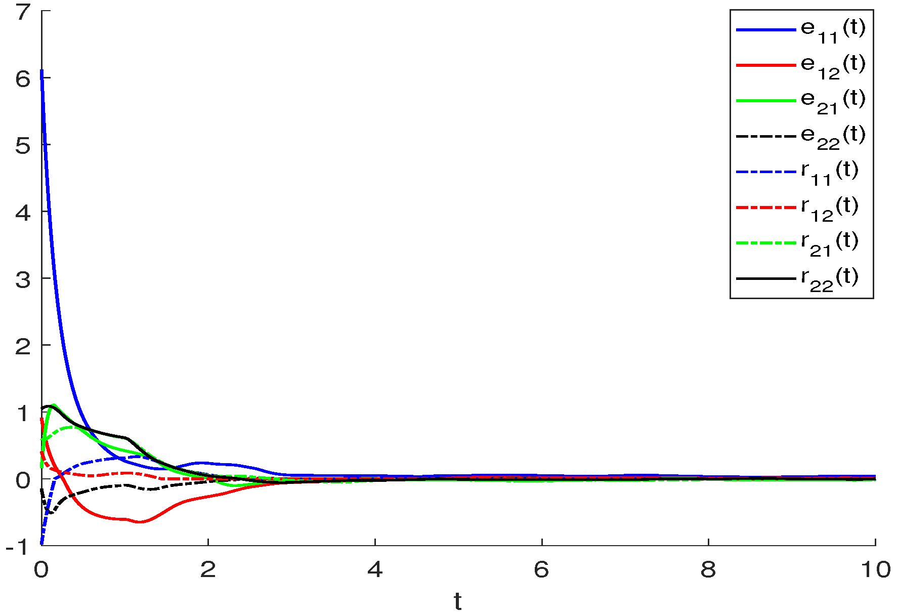
The curves of the real and imaginary parts are represented in Figure 1 and Figure 2, the error curves of the drive–response system e 11 ( t ) , e 12 ( t ) , e 21 ( t ) , e 22 ( t ) , r 11 ( t ) , r 12 ( t ) , r 21 ( t ) and r 22 ( t ) are represented in Figure 3. According to the results, we find that the lines of the same color in the real part (Figure 1) and the imaginary part (Figure 2) of the system will gradually coincide with the increase of time t. In a physical sense, the finite-time synchronization of the master–slave systems of the BAM neural network are realized under controllers (9)–(12). Figure 3 more vividly shows that, under controllers (9)–(12), we can achieve the desired synchronization, and then our theoretical results are verified.
Example 2.
We design the another kind of FTS controller as follows for master system (1) and slave system (2):
Q 1 j ( t ) = β 1 e 1 j ( t ) + sign [ e 1 j ( t ) ] + ψ ( t ) n e 1 j ( t ) 1 ,
ρ 1 j ( t ) = β 2 r 1 j ( t ) + sign [ r 1 j ( t ) ] ,
Q 2 k ( t ) = β 3 e 2 k ( t ) + sign [ e 2 k ( t ) ] ,
ρ 2 k ( t ) = β 4 r 2 k ( t ) + sign [ r 2 k ( t ) ] .
where β 1 = 0.2 , β 2 = 1.5 , β 3 = 1.7 , β 4 = 0.6 ; σ ( t ) = 0.1 sin ( t ) , ψ ( t ) = 1 ln ( t + 1 3 ) 1 t + 1 3 e t , t > 2 3 , and the self-feedback connection weight matrices are as below:
a 11 0 0 a 12 = 3 0 0 5 , a 21 0 0 a 22 = 4 0 0 9 .
Denote J 1 1 R = 0.7 sin ( 2 t ) , J 1 1 I = 0.4 cos ( 2 t ) , J 2 1 R = 1.2 cos ( 2 t ) , J 2 1 I = 0.6 sin ( 2 t ) ; J 1 2 R = 1.8 sin ( 3 t ) , J 1 2 I = 2 cos ( 3 t ) , J 2 2 R = 1.6 cos ( 3 t ) , J 2 2 I = 1.5 sin ( 3 t ) . Then we allow the connection weight matrices and the delayed connection weight matrices of the system to be as follows:
p 1 = 2 + 1.5 i 1.5 i 1 + 0.6 i 1.7 0.9 i , p 2 = 3 + 1.6 i 2 0.5 i 2.3 + 2.6 i 1.6 + 0.7 i ,
q 1 = 1 0.4 i 0.2 + 0.2 i 0.1 + 0.3 i 0.8 + 0.5 i , q 2 = 0.1 + 0.2 i 0.3 + 0.4 i 0.2 + 0.5 i 0.4 + 0.1 i ,
and the active functions are as follows:
f 1 R ( x 21 ( t ) , y 21 ( t ) ) = 0.05 | x 21 ( t ) | + 0.02 | y 21 ( t ) | f 1 I ( x 21 ( t ) , y 21 ( t ) ) = 0.03 | x 21 ( t ) | + 0.04 | y 21 ( t ) | + 1 f 2 R ( x 22 ( t ) , y 22 ( t ) ) = 1.2 | x 22 ( t ) | + 0.75 | y 22 ( t ) | 2 f 2 I ( x 22 ( t ) , y 22 ( t ) ) = 1.5 | x 22 ( t ) | + 0.65 | y 22 ( t ) | 2 ,
h 1 R ( x 11 ( t ) , y 11 ( t ) ) = 0.05 | x 11 ( t ) | + 0.06 | y 11 ( t ) | h 1 I ( x 11 ( t ) , y 11 ( t ) ) = 0.07 | x 11 ( t ) | + 0.08 | y 11 ( t ) | 1.5 h 2 R ( x 12 ( t ) , y 12 ( t ) ) = 1.45 | x 12 ( t ) | + 0.8 | y 12 ( t ) | + 0.2 h 2 I ( x 12 ( t ) , y 12 ( t ) ) = 2 | x 12 ( t ) | + 0.3 | y 12 ( t ) | + 1 .
It is clear that the above activation functions satisfy the conditions ( H 1 ) with L = 2 and 0.1 cos ( t ) = σ ( t ) < τ = 0.5 < 1 . Furthermore, the initial conditions are defined as: x 11 ( 0 ) = 604.39 , x 12 ( 0 ) = 100.2 , x 21 ( 0 ) = 130.47 , x 22 ( 0 ) = 200 ; y 11 ( 0 ) = 120.48 , y 12 ( 0 ) = 500.4 , y 21 ( 0 ) = 110.5 , y 22 ( 0 ) = 70.5 ; z 11 ( 0 ) = 503.52 , z 12 ( 0 ) = 500.6 , z 21 ( 0 ) = 180.5 , z 22 ( 0 ) = 300.2 ; u 11 ( 0 ) = 130.5 , u 12 ( 0 ) = 60.5 , u 21 ( 0 ) = 140.3 , u 22 ( 0 ) = 100.5 . After computation, we have
( A j k * ) = 14 10 6.4 10.4 , ( B j k * ) = 11.2 3.2 3.2 10.4 ,
( C k j * ) = 18.4 10 19.6 9.2 , ( D k j * ) = 2.4 5.6 5.6 4 .
It is easy to verify that all conditions in Theorem 2 are satisfied. Since the study method of FTS and the design of the controllers are different from those in [2,32,34,35,36,37,38,39,40,41,42,43,44,45,46,47,48,49,50,51,52,53,54,55], thus, the results in Example 2 cannot be verified with those in [2,32,34,35,36,37,38,39,40,41,42,43,44,45,46,47,48,49,50,51,52,53,54,55].
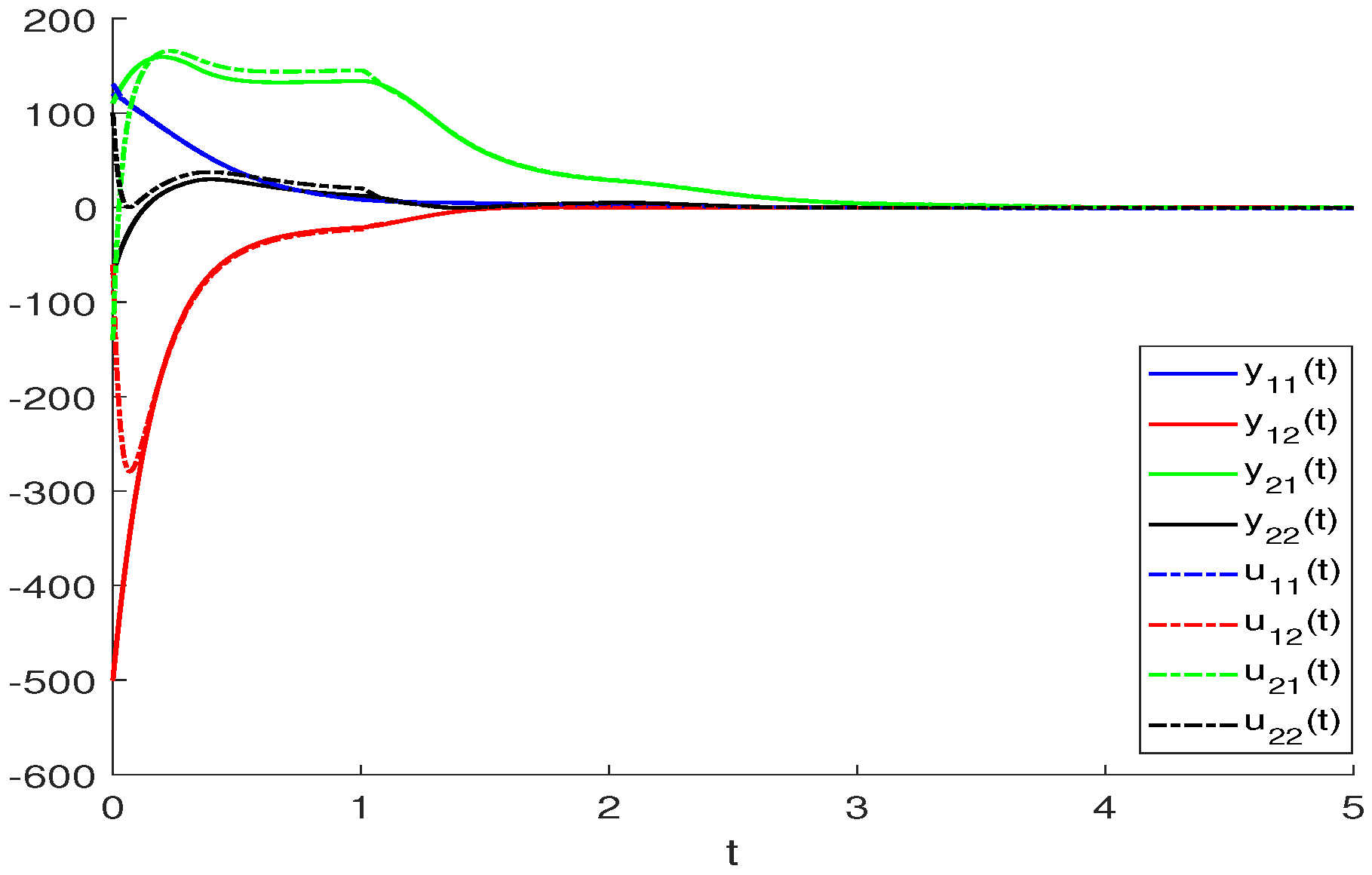
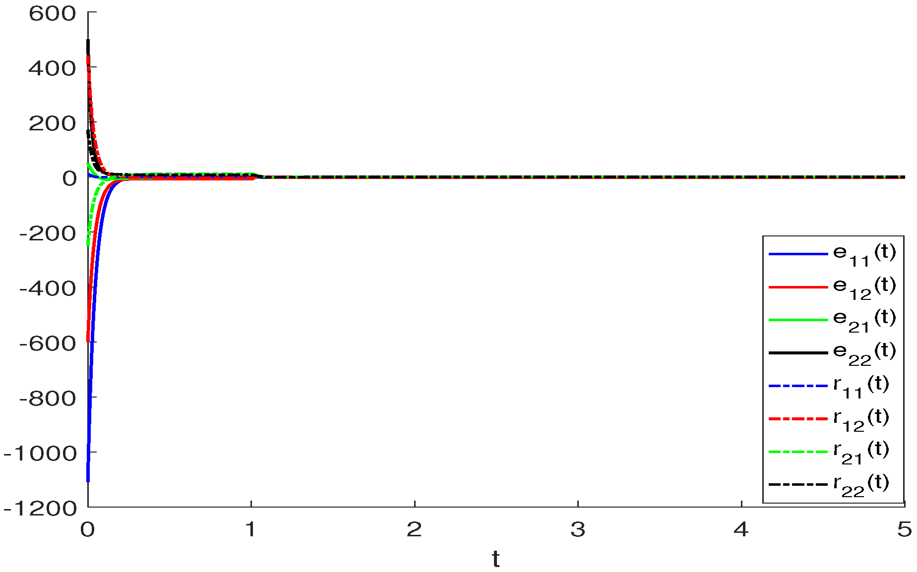
Similar to Example 1, we show the finite-time synchronization phenomenon of BAM neural networks using Figure 4, Figure 5 and Figure 6. We take Figure 4 as an example to explain the result. The solid and dashed line curve represent the real part of master and slave systems for BAM neural networks, respectively, i.e., the numerical solution x 1 j , z 1 j , j = 1.2 ; x 2 k , z 2 k , k = 1 , 2 in systems (3) and (4) under controllers (39)–(42). When t < t 2 , the numerical solution satisfies lim t t 2 | z 1 j ( t ) x 1 j ( t ) | = 0 and when t > t 2 , i.e., the value of t is very large, the distance between x 1 j , x 2 k and z 1 j , z 2 k will equal to 0. Figure 6 shows this result better.

5. Conclusions

In this paper, we consider the FTS for a type of CVBAMNNs with time delays. Without using LF, LKF theory, the differential inequality technique, finite-time stability theorem, graph-theoretic method, the theory of complex functions or the integral inequality method, two novel FTS criteria of delayed CVBAMNNs are achieved to ensure the FTS between the master system and the slave system by applying a quadratic analysis approach and introducing two new inequalities. The inequalities established and inequality techniques in our paper are very novel and the results obtained are different from those in existing papers. In the future, we will study the fixed-time synchronization of neural networks and dynamical systems.

Author Contributions

Conceptualization, Z.Y. and Z.Z.; methodology, Z.Y. and Z.Z.; investigation, Z.Y. and Z.Z.; software, Z.Y.; writing—original draft preparation, Z.Y.; writing—review and editing, Z.Y. and Z.Z.; visualization, Z.Y.; supervision, Z.Z.; project administration, Z.Y. and Z.Z. All authors have read and agreed to the published version of the manuscript.

Funding

This research was funded by Doctoral Research Launch Fund (XJ2022001501) from Hubei University of Technology.

Institutional Review Board Statement

Not applicable.

Informed Consent Statement

Not applicable.

Data Availability Statement

All data included in this study are available upon request by contacting the corresponding author.

Acknowledgments

We are thankful to the reviewers for their constructive comments which helped us to improve the manuscript.

Conflicts of Interest

The authors declare no conflict of interest. The funders had no role in the design of the study; in the collection, analyses, or interpretation of data; in the writing of the manuscript; or in the decision to publish the results.

References

  1. Duan, L.; Shi, M.; Huang, C.X.; Fang, X.W. Synchronization in finite-/fixed-time of delayed diffusive complex-valued neural networks with discontinuous activations. Chaos Solitons Fractals 2021, 142, 110386. [Google Scholar] [CrossRef]
  2. Zhang, J.M.; Bao, H. Synchronization of fractional-order three-neuron complex-valued BAM neural networks with multiple time delays via discontinuous neuron activations. In Proceedings of the 2018 Chinese Control Furthermore, Decision Conference (CCDC), Shenyang, China, 9–11 June 2018; pp. 1093–1098. [Google Scholar]
  3. Kumar, A.; Das, S.; Rajeev; Yadav, V.K. Global exponential synchronization of complex-valued recurrent neural networks in presence of uncertainty along with time-varying bounded and unbounded delay terms. Int. J. Dyn. Control 2021, 10, 902–916. [Google Scholar] [CrossRef]
  4. Li, L.; Chen, W.S.; Wu, J. Global Exponential stability and synchronization for novel complex-valued neural networks with proportional delays and inhibitory factors. IEEE Trans. Cybern. 2021, 51, 2142–2152. [Google Scholar] [CrossRef]
  5. Yuan, M.M.; Wang, W.P.; Wang, Z.; Luo, X.; Kurths, J. Exponential synchronization of delayed memristor-based uncertain complex-valued neural networks for image protection. IEEE Trans. Neural Netw. Learn. Syst. 2021, 32, 151–165. [Google Scholar] [CrossRef]
  6. Zhu, S.; Liu, D.; Yang, C.Y.; Fu, J. Synchronization of memristive complex-valued neural networks with time delays via pinning control method. IEEE Trans. Cybern. 2020, 50, 3806–3815. [Google Scholar] [CrossRef]
  7. Liu, M.; Li, Z.F.; Jiang, H.J.; Hu, C.; Yu, Z.Y. Exponential synchronization of complex-valued neural networks via average impulsive interval strategy. Neural Process. Lett. 2020, 52, 1377–1394. [Google Scholar] [CrossRef]
  8. Zhang, W.W.; Zhang, H.; Cao, J.D.; Zhang, H.M.; Chen, D.Y. Synchronization of delayed fractional-order complex-valued neural networks with leakage delay. Phys. A Stat. Mech. Its Appl. 2020, 556, 124710. [Google Scholar] [CrossRef]
  9. Pan, C.N.; Bao, H.B. Exponential synchronization of complex-valued memristor-based delayed neural networks via quantized intermittent control. Neurocomputing 2020, 404, 317–328. [Google Scholar] [CrossRef]
  10. Yu, J.; Hua, C.; Jiang, H.J.; Wang, L.M. Exponential and adaptive synchronization of inertial complex-valued neural networks: A non-reduced order and non-separation approach. Neural Netw. 2020, 124, 50–59. [Google Scholar] [CrossRef]
  11. Liu, M.J.; Wang, X.R.; Zhang, Z.Y.; Wang, Z. Global synchronization of complex-valued neural networks with stochastic disturbances and time-varying delay. IEEE Access 2019, 7, 182600–182610. [Google Scholar] [CrossRef]
  12. Wang, P.F.; Zou, W.Q.; Su, H.; Feng, J.Q. Exponential synchronization of complex-valued delayed coupled systems on networks with aperiodically on-off coupling. Neurocomputing 2019, 369, 155–165. [Google Scholar] [CrossRef]
  13. Pan, J.S.; Zhang, Z.Q. Finite-time synchronization for delayed complex-valued neural networks via the exponential-type controllers of time variable. Chaos Solitons Fractals 2021, 146, 110897. [Google Scholar] [CrossRef]
  14. Aouiti, C.; Bessifi, M. Sliding mode control for finite-time and fixed-time synchronization of delayed complex-value d recurrent neural networks with discontinuous activation functions and nonidentical parameters. Eur. J. Control 2021, 59, 109–122. [Google Scholar] [CrossRef]
  15. Yu, T.H.; Cao, J.D.; Rutkowski, L.; Luo, Y.P. Finite-time synchronization of complex-valued memristive-based neural networks via hybrid control. IEEE Trans. Neural Netw. Learn. Syst. 2021, 33, 3938–3947. [Google Scholar] [CrossRef]
  16. Luo, F.; Xiang, Y.; Wu, E.L. Finite-time synchronization of coupled complex-valued chaotic systems with time-delays and bounded perturbations. Mod. Phys. Lett. B 2021, 35, 2150130. [Google Scholar] [CrossRef]
  17. Song, X.N.; Man, J.T.; Song, S.; Zhang, Y.J.; Ning, Z.K. Finite/fixed-time synchronization for Markovian complex-valued memristive neural networks with reaction-diffusion terms and its application. Neurocomputing 2020, 414, 131–142. [Google Scholar] [CrossRef]
  18. Xiong, K.L.; Yu, J.; Hua, C.; Wen, S.P.; Jiang, H.J. Finite-time synchronization of fully complex-valued networks with or without time-varying delays via intermittent control. Neurocomputing 2020, 413, 173–184. [Google Scholar] [CrossRef]
  19. Aouiti, C.; Bessifi, M.; Li, X.D. Finite-time and fixed-time synchronization of complex-valued recurrent neural networks with discontinuous activations and time-varying delays. Circuits Syst. Signal Process. 2020, 39, 5406–5428. [Google Scholar] [CrossRef]
  20. Xu, Y.; Li, Y.Z.; Li, W.X. Adaptive finite-time synchronization control for fractional-order complex-valued dynamical networks with multiple weights. Commun. Nonlinear Sci. Numer. Simul. 2020, 85, 105239. [Google Scholar] [CrossRef]
  21. Xiong, K.L.; Yu, J.; Hu, C.; Jiang, H.J. Synchronization in finite/fixed time of fully complex-valued dynamical networks via nonseparation approach. J. Frankl. Inst. 2021, 358, 2367–2381. [Google Scholar] [CrossRef]
  22. Xu, Y.; Li, W.X. Finite-time synchronization of fractional-order complex-valued coupled systems. Phys. A 2020, 549, 123903. [Google Scholar] [CrossRef]
  23. Zheng, B.B.; Hu, C.; Yu, J.; Jiang, H.J. Finite-time synchronization of fully complex-valued neural networks with fractional-order. Neurocomputing 2020, 373, 70–80. [Google Scholar] [CrossRef]
  24. Wang, Z.Y.; Cao, J.D.; Cai, Z.W.; Huang, L.H. Periodicity and finite-time periodic synchronization of discontinuous complex-valued neural networks. Neural Netw. 2019, 119, 249–260. [Google Scholar] [CrossRef]
  25. Liu, Y.J.; Huang, J.J.; Qin, Y.; Yang, X.B. Finite-time synchronization of complex-valued neural networks with finite-time distributed delays. Neurocomputing 2020, 416, 152–157. [Google Scholar] [CrossRef]
  26. Sun, K.L.; Zhu, S.; Wei, Y.C.; Zhang, X.K.; Gao, F. Finite-time synchronization of memristor-based complex-valued neural networks with time delays. Phys. Lett. A 2019, 383, 2255–2263. [Google Scholar] [CrossRef]
  27. Zhang, Z.Y.; Liu, X.P.; Lin, C.; Chen, B. Finite-time synchronization for complex-valued recurrent neural networks with time delays. Hindawi Complex. 2018, 2018, 8456737. [Google Scholar] [CrossRef] [Green Version]
  28. Wu, E.L.; Yang, X.S.; Xu, C.; Alsaadi, F.E.; Hayat, T. Finite-time synchronization of complex-valued delayed neural networks with discontinuous activations. Asian J. Control. 2018, 20, 2237–2247. [Google Scholar] [CrossRef]
  29. Liu, Y.J.; Qin, Y.; Huang, J.J.; Huang, T.W.; Yang, X.B. Finite-time synchronization of complex-valued neural networks with multiple time-varying delays and infinite distributed delays. Neural Process. Lett. 2019, 50, 1773–1787. [Google Scholar] [CrossRef]
  30. Zhang, Z.Q.; Li, A.L.; Yu, S.H. Finite-time synchronization for delayed complex-valued neural networks via integrating inequality method. Neurocomputing 2018, 318, 248–260. [Google Scholar] [CrossRef]
  31. Zhang, C.; Wang, X.Y.; Wang, S.B.; Zhou, W.J.; Xia, Z.Q. Finite-time synchronization for a class of fully complex-valued networks with coupling delay. IEEE Access 2018, 6, 17923–17932. [Google Scholar] [CrossRef]
  32. Guo, R.N.; Zhang, Z.Y.; Chen, J.; Lin, C.; Liu, Y. Finite-time synchronization for delayed complex-valued BAM neural networks. In Proceedings of the 2017 Chinese Automation Congress (CAC), Jinan, China, 20–22 October 2017; pp. 872–877. [Google Scholar]
  33. Zhou, C.; Zhang, W.L.; Yang, X.S.; Xu, C.; Feng, J.W. Finite-time synchronization of complex-valued neural networks with mixed delays and uncertain perturbations. Neural Process. Lett. 2017, 46, 271–291. [Google Scholar] [CrossRef]
  34. Manikandan, M.; Ratnavelu, K.; Balasubramaniam, P.; Ong, S.H. Synchronization of BAM Cohen-Grossberg FCNNs with mixed time delays. Iran. J. Fuzzy Syst. 2021, 18, 159–173. [Google Scholar]
  35. Li, L.C.; Xu, R.; Gan, Q.T.; Lin, J.Z. A switching control for finite-time synchronization of memristor-based BAM neural networks with stochastic disturbances. Nonlinear Anal. Model. Control 2020, 25, 958–979. [Google Scholar] [CrossRef]
  36. Zhang, L.Z.; Yang, Y.Q. Finite time impulsive synchronization of fractional order memristive BAM neural networks. Neurocomputing 2020, 384, 213–224. [Google Scholar] [CrossRef]
  37. Yang, Z.Y.; Li, J.W.; Niu, Y.Q. Finite-time stabilization of fractional-order delayed bidirectional associative memory neural networks. Sci. Asia 2019, 45, 589–596. [Google Scholar] [CrossRef] [Green Version]
  38. Tang, R.Q.; Yang, X.S.; Wan, X.X.; Zou, Y.; Cheng, Z.S.; Fardoun, H.M. Finite-time synchronization of nonidentical BAM discontinuous fuzzy neural networks with delays and impulsive effects via non-chattering quantized control. Commun. Nonlinear Sci. Numer. Simul. 2019, 78, 104893. [Google Scholar] [CrossRef]
  39. Pratap, A.; Raja, R.; Rajchakit, G.; Cao, J.D.; Bagdasar, O. Mittag–Leffler state estimator design and synchronization analysis for fractional-order BAM neural networks with time delays. Int. J. Adapt. Control. Signal Process. 2019, 33, 855–874. [Google Scholar] [CrossRef]
  40. Aouiti, C.; Li, X.D.; Miaadi, F. A new LMI approach to finite and fixed time stabilization of high-order class of BAM neural networks with time-varying delays. Neural Process. Lett. 2019, 50, 815–838. [Google Scholar] [CrossRef]
  41. Wang, W.P.; Wang, X.; Luo, X.; Yuan, M.M. Finite-time projective synchronization of memristor-based BAM neural networks and applications in image encryption. IEEE Access 2018, 6, 56457–56476. [Google Scholar] [CrossRef]
  42. Zhang, Y.P.; Li, L.X.; Peng, H.P.; Xiao, J.H.; Yang, Y.X.; Zheng, M.W.; Zhao, H. Finite-time synchronization for memristor-based BAM neural networks with stochastic perturbations and time-varying delays. Int. J. Robust Nonlinear Control 2018, 28, 5118–5139. [Google Scholar] [CrossRef]
  43. Sader, M.; Abdurahman, A.; Jiang, H.J. General decay synchronization of delayed BAM neural networks via nonlinear feedback control. Appl. Math. Comput. 2018, 337, 302–314. [Google Scholar] [CrossRef]
  44. Chen, C.; Li, L.X.; Peng, H.P.; Yang, Y.X. Adaptive synchronization of memristor-based BAM neural networks with mixed delays. Appl. Math. Comput. 2018, 322, 100–110. [Google Scholar] [CrossRef]
  45. Zhang, Z.Y.; Liu, X.P.; Guo, R.N.; Lin, C. Finite-time stability for delayed complex-valued BAM neural networks. Neural Process. Lett. 2018, 48, 179–193. [Google Scholar] [CrossRef]
  46. Xu, C.J.; Li, P.L.; Pang, Y.C. Finite-time stability for fractional-order bidirectional associative memory neural networks with time delays. Commun. Theor. Phys. 2017, 67, 137–142. [Google Scholar] [CrossRef]
  47. Rajivganthi, C.; Rihan, F.; Lakshmanan, S.; Muthukumar, P. Finite-time stability analysis for fractional-order Cohen–Grossberg BAM neural networks with time delays. Neural Comput. Appl. 2018, 29, 1309–1320. [Google Scholar] [CrossRef]
  48. Xiao, J.Y.; Zhong, S.M.; Li, Y.T.; Xu, F. Finite-time Mittag–Leffler synchronization of fractional-order memristive BAM neural networks with time delays. Neurocomputing 2017, 219, 431–439. [Google Scholar] [CrossRef]
  49. Chen, Z.W.; Zhang, R.J.; Wang, L.S. Finite-time stochastic synchronization for a class of BAM neural networks with uncertain parameters. Commun. Appl. Anal. 2016, 20, 263–276. [Google Scholar]
  50. Zhang, Z.Q.; Cao, J.D. Novel finite-time synchronization criteria for inertial neural networks with time delays via integral inequality method. IEEE Trans. Neural Netw. Learn. Syst. 2019, 30, 1476–1485. [Google Scholar] [CrossRef]
  51. Zhang, Z.Q.; Cao, J.D. Finite-time synchronization for fuzzy inertial neural networks by maximum value approach. IEEE Trans. Fuzzy Syst. 2022, 30, 1436–1446. [Google Scholar] [CrossRef]
  52. Zhang, Z.Q.; Chen, M.; Li, A.L. Further study on finite-time synchronization for delayed inertial neural networks via inequality skills. Neurocomputing 2020, 373, 15–23. [Google Scholar] [CrossRef]
  53. Yang, Z.; Zhang, Z. Finite-time synchronization analysis for BAM neural networks with time-varying delays by applying the maximum-value approach with new inequalities. Mathematics 2022, 10, 835. [Google Scholar] [CrossRef]
  54. Wang, J.; Tian, Y.; Hua, L.; Shi, K.; Zhong, S.; Wen, S. New results on finite-time synchronization control of Chaotic memristor-based inertial neural networks with time-varying delays. Mathematics. Mathematics 2023, 11, 684. [Google Scholar] [CrossRef]
  55. Yang, W.; Xiao, L.; Huang, J.; Yang, J. Fixed-time synchronization of neural networks based on quantized intermittent control for image protection. Mathematics 2021, 9, 3086. [Google Scholar] [CrossRef]
  56. Wang, S.; Zhang, H.; Zhang, W.; Zhang, H. Finite-time projective synchronization of Caputo type fractional complex-valued delayed neural networks. Mathematics 2021, 9, 1406. [Google Scholar] [CrossRef]
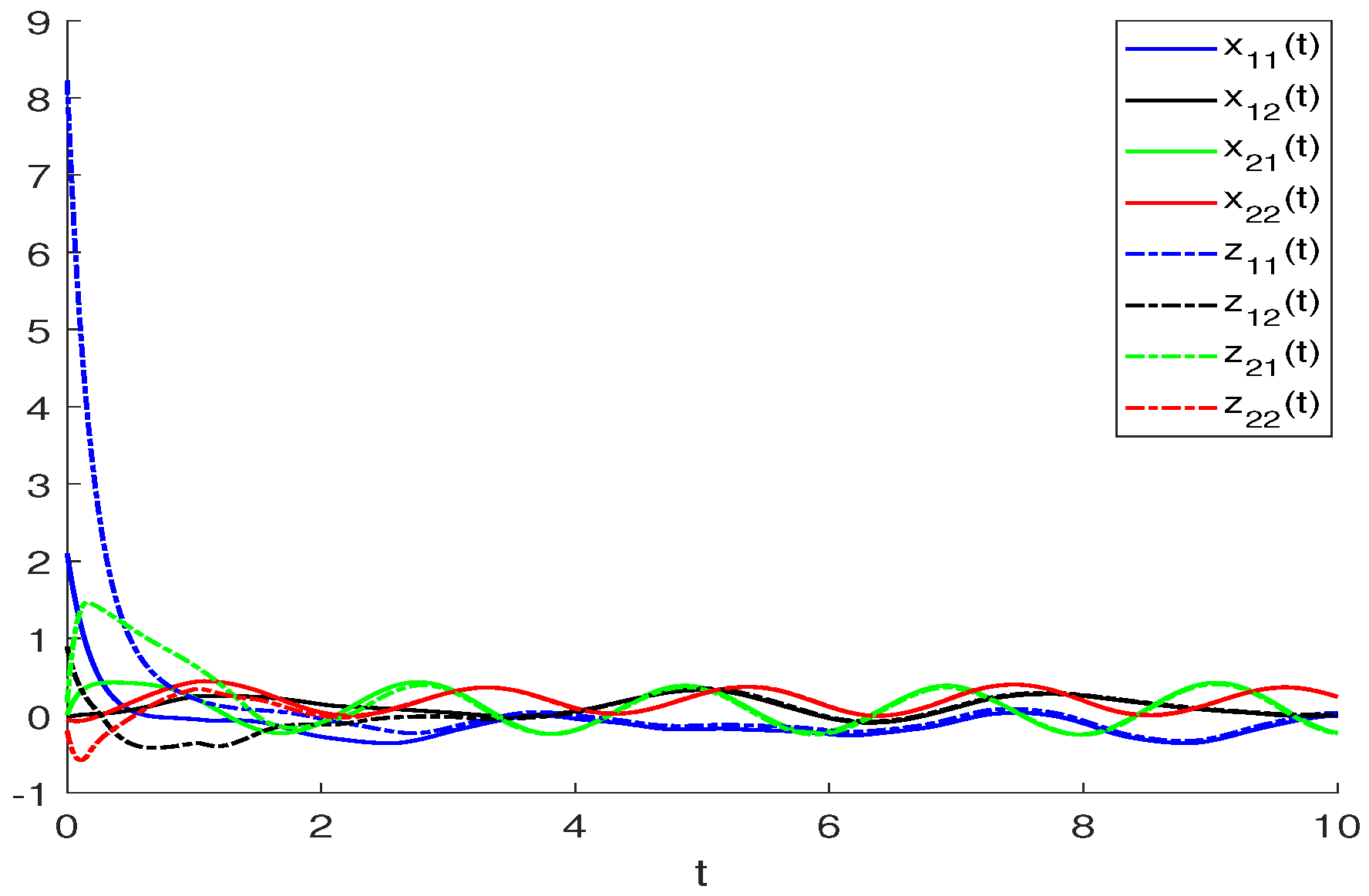
Figure 1. The curves of the real parts in Example 1.
Mathematics 11 01378 g001
Figure 2. The curves of the imaginary parts in Example 1.
Mathematics 11 01378 g002
Figure 3. The curves of the error system in Example 1.
Mathematics 11 01378 g003
Figure 4. The curves of the real parts in Example 2.
Mathematics 11 01378 g004
Figure 5. The curves of the imaginary parts in Example 2.
Mathematics 11 01378 g005
Figure 6. The curves of the error system in Example 2.
Mathematics 11 01378 g006
Disclaimer/Publisher’s Note: The statements, opinions and data contained in all publications are solely those of the individual author(s) and contributor(s) and not of MDPI and/or the editor(s). MDPI and/or the editor(s) disclaim responsibility for any injury to people or property resulting from any ideas, methods, instructions or products referred to in the content.