Article

Research on Magnetic Levitation Control Method under Elastic Track Conditions Based on Backstepping Method

1
College of Intelligence Science and Technology, National University of Defense Technology, Changsha 410073, China
2
Hunan Provincial Key Laboratory of Electromagnetic Levitation and Propulsion Technology, Changsha 410073, China
*
Author to whom correspondence should be addressed.
Mathematics 2024, 12(13), 2134; https://doi.org/10.3390/math12132134
Submission received: 29 May 2024 / Revised: 25 June 2024 / Accepted: 4 July 2024 / Published: 7 July 2024

Abstract

:
The vehicle–guideway coupled self-excited vibration of maglev systems is a common control instability problem in maglev traffic while the train is suspended above flexible girders, and it seriously affects the suspension stability of maglev vehicles. In order to solve this problem, a nonlinear dynamic model of a single-point maglev system with elastic track is established in this paper, and a new and more stable adaptive backstepping control method combined with magnetic flux feedback is designed. In order to verify the control effect of the designed control method, a maglev vehicle–guideway coupled experimental platform with elastic track is built, and experimental verifications under rigid and elastic conditions are carried out. The results show that, compared with the state feedback controller based on the feedback linearization controller, the adaptive backstepping control law proposed in this paper can achieve stable suspension under extremely low track stiffness, and that it shows good stability and anti-interference abilities under elastic conditions. This work has an important meaning regarding its potential to benefit the advancement of commercial maglev lines, which may significantly enhance the stability of the maglev system and reduce the cost of guideway construction.

1. Introduction

Since the concept of maglev trains was first proposed in 1922, the technology related to maglev trains has become increasingly mature after more than 100 years of development. Now, the EMS (electromagnetic suspension) maglev train has been successfully commercialized in Changsha, Shanghai, Beijing and other places around the world. Maglev trains have shown good development potential, and provided another possibility for future transportation with its advantages of low noise, low energy consumption, and high comfort [1,2,3].
As a nonlinear, open-loop unstable system, the suspension control system has a crucial impact on the safety, comfort and reliability of maglev trains. The quality of the suspension performance directly determines whether the maglev train can operate normally or not. Many problems have been encountered in the process of developing practical engineering applications, including vehicle–guideway coupled vibration, the stability of the suspension system in the presence of track irregularities, and the time-varying system parameters, which bring challenges to the suspension control of maglev trains [4,5].
Among them, vehicle–guideway coupled vibration is one of the typical problems encountered in engineering applications. For example, vehicle–guideway coupled vibration has occurred on the AMT maglev test system in America and the KIMM maglev test line in Korea. In some cases, the vibration leads to the failure of suspension, which directly affects the test [6]. It is reported that on the Shanghai high-speed maglev line, vehicle–guideway coupled vibration occasionally occurs, which affects the suspension stability [7]. This problem seriously affects the life of the track and increases the maintenance cost of maglev trains, and thus needs to be solved.
Many researchers have also studied the principle of the vehicle–rail coupled vibration problem. In [8], it was pointed out that the first-order modal frequency of the suspended beam is closely related to the generation of vehicle–guideway coupled self-excited vibration, and a virtual tuned mass damper scheme was proposed to suppress the self-excited vibration. In [9], a vertical vehicle–track–bridge interaction model was established, and the influence of the track vibration characteristics on the coupled vibration was analyzed. It was pointed out that the vibration frequency of the F-rail itself, as well as its periodic and irregular deformation, are the two main factors affecting vehicle–guideway coupled vibration.
In fact, vehicle–guideway coupled vibration occurs only when the electromagnetic force brings energy to the track to enlarge the amplitude of the track vibration; this means that the energy transfer from the suspension controller to the track is largely due to the use of an improper control algorithm. In [10], it is pointed out that vehicle–guideway coupled vibration is related to a mismatch between the feedback parameters of the controller. On the other hand, the guideway parameters, such as its stiffness and mass, also have prominent influences on the coupled vibration problem.
To ameliorate this coupled vibration, some researchers have proposed the use of air spring suspension to suppress the coupled vibration [11], and it has been pointed out that increasing the weight of the track also has a good effect on suppressing the coupled vibration. Some researchers have also proposed the use of a virtual sky-hooked damper to suppress the self-excited vibration of magnetic levitation [12]. But the track construction cost accounts for a large proportion of the overall cost of the system, so increasing the stiffness and weight of the track will undoubtedly increase the construction cost of the maglev train system significantly. Therefore, it is more practical to improve the suspension control algorithms to solve the coupled vibration problem.
As the most classic control algorithm, PID and the improved PID algorithm are still widely used in the suspension control of maglev trains [13,14]. However, the PID algorithm finds it difficult to solve the coupled vibration problem when the amplitude of the vibration is large. Meanwhile, the classical linearized suspension model at the equilibrium point that has been commonly used in controller design is also quite unfavorable in control [15]. It does not concern the elasticity of the track and brings large systematic errors when the suspension gap is far from the equilibrium point (such as when vehicle–girder coupled resonance occurs), which degrades the performance of the controller.
In order to solve this problem, many researchers have designed nonlinear control algorithms based on nonlinear models. In [15], a super-twisting sliding mode algorithm that was shown to have better performance than traditional PI controllers in the simulation was proposed. In addition, a control strategy based on the precise model of a non-singular robust sliding mode control was designed in [16], but the system model used therein was the classical linear model, which limits the performance of the system to a certain extent. In [17], the electromagnetic force model in the system model was revised, and a more accurate composite controller was proposed based on the new force model, which showed better anti-disturbance abilities.
Recently, adaptive control methods with learning methods or neural networks have been proposed to enhance the suppression of the vibration. In [4], an optimal tracking controller based on reinforcement learning that dynamically adjusts the control parameters is proposed. Since it can compensate for the time delay of input, it has a good suspension performance and can avoid coupled vibration to a certain extent. In [18], an adaptive control method based on a neural network is proposed. The radial basis function neural network that can effectively deal with external disturbances such as suspension load changes is integrated. On the basis of this algorithm, in [19], the system identification is added to the design of the RBF network adaptive control algorithm, which avoids the error caused by linearization and can obviously improve the robustness of the system.
Among the nonlinear control methods, the backstepping method has a good effect in fields such as rotorcraft, helicopters, underwater vehicles and robots [20,21,22]. It has also been used in maglev levitation control and proven to have good effects during simulation [23,24]. When the track state is considered in the system modeling, the method should be able to suppress the track vibration and thus the vehicle–guideway coupled vibration.
Lyapunov stability theory is widely used to assess the stability and robustness of magnetic levitation systems. Magnetic levitation systems usually involve nonlinear dynamical properties, so it is crucial to understand the stability of the system at different operating points or under different operating conditions. However, in the field of vehicle–guideway coupled self-excited vibration, there are fewer control algorithms using Lyapunov stability theory.
Moreover, the square of the magnetic flux is approximately proportional to the electromagnetic force. Compared with the suspension control schemes that mostly use the suspension gap and the current feedback signals, it is believed that the control algorithms with magnetic flux feedback could provide better stability in the presence of track elasticity [25,26]. In [27], magnetic flux feedback signals were used in the PID controller. This increased the system damping by importing the differential of the magnetic flux to suppress the vibration, and a good control effect was achieved. Therefore, the magnetic flux signal is used for control in this paper. On this basis, a nonlinear model of the magnetic suspension system is established, and the elastic guideway is also considered.
In this paper, to stabilize the vehicle–guideway coupled system, an adaptive backstepping controller is designed based on the Lyapunov stability theory. Since the elasticity of the guideway is also considered in the Lyapunov function, the stability of the maglev vehicle–guideway coupled system can be guaranteed.
To test the effect of the proposed algorithm, a maglev vehicle–guideway coupled experiment platform is designed with a rather light track that is supported by low-stiffness springs. The experiments show that the proposed control strategy is able to eliminate the coupled self-excited vibration effectively, and can achieve stable control under the condition of a very low track-to-vehicle mass ratio.
The control strategy proposed in this paper has low requirements regarding the stiffness and mass of the track; therefore, it is able to reduce the cost of track construction and thus reduce the overall construction cost of maglev transport.

2. Modeling of the Vehicle–Guideway System

The maglev train system consists of three parts: the carriage, the maglev bogie and the track. As the minimum control structure of the EMS maglev vehicle, the single-point suspension system, which is composed of a single suspension electromagnet and an elastic track, is selected as the research object. Although simple, this model has been used for studies of the maglev vehicle–guideway interaction problem by many researchers.

2.1. Modeling of the Single-Point Suspension System

A longitudinal cross-section of the EMS maglev train and the simplified single-point suspension structure are shown in Figure 1. The parameters used in the modeling are shown in Table 1.
The dynamic equation of the electromagnet is given by the following:
m 1 z ¨ 1 = m 1 g F e + f d 1 ,
where the electromagnetic force can be deduced [25]:
F e = d W d z 1 = S μ 0 B 2 .
As shown in Equation (2), the electromagnetic force is proportional to the square of the magnetic flux density. The voltage balance equation is as follows:
u = R i + d N ϕ 1 d t = R i + N S d B d t .
In the theoretical calculations, the leakage flux is neglected. Therefore, the magnetic flux across the electromagnet air gap can be obtained:
ϕ 1 = F m R m = μ 0 S N i 2 z 1 .
Thus, the magnetic flux density is as follows:
B = ϕ 1 S = μ 0 N i 2 z 1 .
Substituting Equation (5) into Equation (3) yields the following:
u = 2 R z 1 μ 0 N B + N S d B d t .
The mathematical model of the suspension system was obtained by combining the above equations:
z ¨ 1 = g F e m 1 B ˙ = 2 R μ 0 S N 2 z 1 B + 1 N S u F e = S μ 0 B 2 .

2.2. Modeling of the Vehicle–Guideway System

An elevated guideway is frequently used in the maglev system. Figure 2 shows the CMS-04 urban maglev vehicle traveling along an elevated concrete box girder. Note that the steel tracks are paved above the upper surface of the girder.
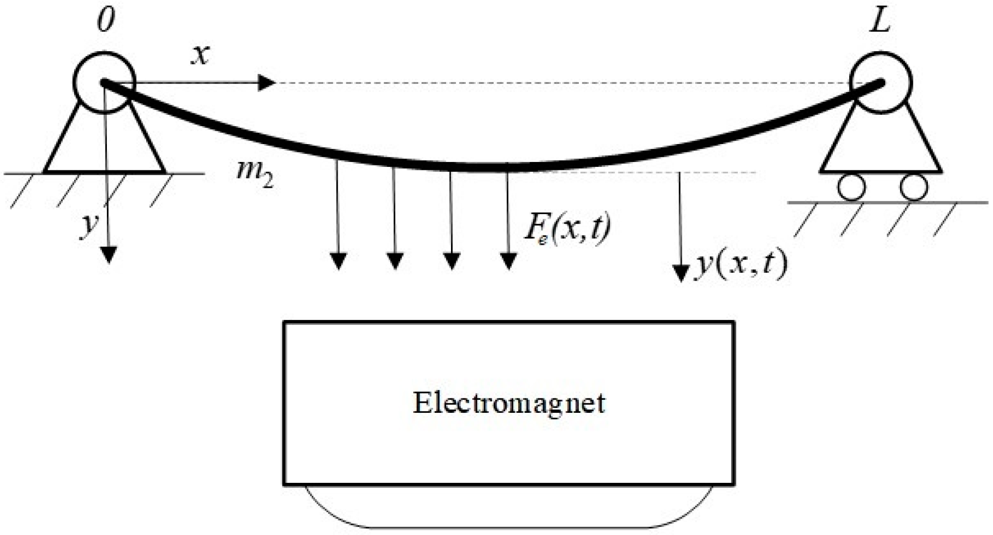
The girder shown in Figure 2 is slenderer compared with other girders, and it more easily suffers from the vehicle–girder coupled self-excited vibration problem since the slenderer the girder, the more flexible the girder is. Considering that the dimensions of the girder cross-section are far smaller than the length of the girder, the model of the girder can be simplified as a Bernoulli–Eulerian beam, and the vehicle can be simplified as a concentrated mass, as shown in Figure 3.
In Figure 3, Fe is the electromagnetic force acting on the track beam, and L and m2 are the length and mass of the track beam, respectively. Only the vertical motion of the track is considered, and the motion equation of the track is given by the following:
E I 4 y x 4 + ρ l 2 y t 2 = F e ( x , t ) .
Here, ρ l is the linear density of the track beam, and EI is the bending stiffness of the track beam. The displacement of the beam can be described as follows:
y ( x , t ) = i = 1 φ i ( x ) q i ( t ) .
Here, q i ( t ) and φ i ( x ) are the i-th order generalized time-domain coordinates and normalized modal function of the track beam, respectively. The mode shapes differ as the support conditions vary. As in [28], the mode shapes of a girder with flexible pier supports are discussed, and the results show that the mode shape and the related modal frequencies of the girder are different from those of the simply supported beam. However, the dynamic equations of the girder with complex support conditions can also be transmitted as a composition comprising a series of second-order mass-spring oscillators, the same as that of a simply supported beam. Therefore, many researchers still use the simply supported beam model to study maglev vehicle–girder interaction problems. For a simply supported beam, its modal frequencies and modal functions are as follows:
ω i = i π L E I ρ l
φ i ( x ) = sin i π x L .
Substitute Equation (11) into Equation (9), and multiply both sides of the equation by φ i ( x ) . Then, by integrating along the track beam from zero to L and using the orthogonality condition of the beam, one can obtain the following:
q ¨ i ( t ) + ω i 2 q i ( t ) = Q i ( x ) .
Here, Q i ( x ) is the generalized force of the i-th mode, and
Q i ( x ) = 0 L F e ( x , t ) φ i ( x ) d x .
Considering the damping of the guideway, Equation (12) can be rewritten as follows:
q ¨ i ( t ) + 2 c i ω i q ˙ i ( t ) + ω i 2 q i ( t ) = Q i ( x ) .
Here, c i is the damping of the track beam. In practice, it is found that the self-excited vibration only occurs at the lower vibration modes of the girder; as an example, only the first-order mode of the track is temporarily considered. Since the length of the electromagnet is much shorter than the girder, it is reasonable to treat the electromagnetic force of the electromagnet as a concentrated force that acts on a point of the track beam, which enables Equation (14) to be simplified as the following form:
q ¨ 1 ( t ) + 2 c 1 ω 1 q ˙ 1 ( t ) + ω 1 2 q 1 ( t ) = 2 φ 1 2 ( x ) m 2 F ( t ) .
Taking the states of the track beam as part of the state of the system, the mathematical model of the entire system can be written as follows:
z ¨ 1 = g F m 1 q ¨ 1 = 2 φ 1 2 ( x ) m 2 F 2 c 1 ω 1 q ˙ 1 ω 1 2 q 1 B ˙ = 2 R μ 0 S N 2 q 1 B 3 + 1 N S u F = S μ 0 B 2 .
The transfer function of the entire system is as follows:
G H ( s ) = Δ F ( s ) Δ z 1 ( s ) = G ( s ) 1 + G ( s ) H ( s ) ,
where
G ( s ) = S N B 0 ( z 10 k u k p i 0 R ) m 1 s 2 m 1 μ 0 2 S N 2 s 3 + 2 μ 0 z 10 m 1 R s 2 + S N B 0 k u k d s + S N B 0 ( z 10 k u k p i 0 R ) ,
H ( s ) = 2 φ 1 2 m 2 ( s 2 + 2 c 1 ω 1 s + ω 1 2 ) ,
where z 10 is the expectation gap, i 0 is the current on the winding under steady-state levitation conditions, B 0 is the magnetic induction of the air gap under steady-state levitation conditions, and k u , k p and k d are the current loop gain, proportional and differential gain of the system, respectively.
The state space of the system is represented as follows:
x · = A x + B u y = C x ,
where
A = 0 1 0 0 0 0 0 0 0 2 S B 0 m 1 μ 0 0 0 0 1 0 0 0 ω 1 2 2 c 1 ω 1 4 φ 1 2 S m 2 μ 0 B 0 2 R μ 0 S N 2 B 0 + k u 2 μ 0 N B 0 k p k u k d k u k p 2 μ 0 N B 0 0 k u δ 0 2 R μ 0 S N 2 z 10 ,
B = 0 0 0 0 1 N S ,
C = 1 0 0 0 0 ,
The system controllability matrix can be derived as follows:
M = B A B A 2 B = 0 0 0 0 1 0 0 0 1 0 0 0 1 0 0 0 1 0 0 0 1 0 0 0 0 ,
and the rank of the controllability matrix of Equation (24) is as follows:
r a n k ( M ) = 5 .
According to the rank criterion of system controllability, the system is completely controllable.

3. Design of the Levitation Control Scheme

The mathematical model of the maglev–guideway coupled system has been established in the previous section. Here, the backstepping method is considered to design the controller. Using the Lyapunov stability theory, the integral stability of the maglev system comprising elastic tracks can be guaranteed.

3.1. Design of Control Law Based on Backstepping Method

First, define
x 1 = z 1 x 2 = z ˙ 1 x 3 = q 1 x 4 = q ˙ 1 ,
and
e 1 = x 1 x ^ 1 e 2 = x 2 x ^ 2 e 3 = x 3 x ^ 3 e 4 = x 4 x ^ 4 .
Here, x ^ j , ( j = 1 , 2 , 3 , 4 ) is the expected value of each state variable, and e j is the state error between the actual value and the expected value. Then, the state space equation can be obtained:
x ˙ 1 = x 2 x ˙ 2 = g S μ 0 m 1 B 2 x ˙ 3 = x 4 x ˙ 4 = 2 φ 1 2 ( x ) S μ 0 m 2 B 2 2 c 1 ω 1 x ˙ 4 ω 1 2 x 3 ,
and
e ˙ 1 = e 2 + x ^ 2 x ^ ˙ 1 e ˙ 2 = g S μ 0 m 1 B 2 x ^ ˙ 2 e ˙ 3 = e 4 + x ^ 4 x ^ ˙ 3 e ˙ 4 = 2 φ 1 2 ( x ) S μ 0 m 2 B 2 2 c 1 ω 1 e 4 ω 1 2 e 3 + 2 c 1 ω 1 x ^ 4 + ω 1 2 x ^ 3 .
When using the backstepping method, it is necessary to solve the differential of the state variable many times; for the fourth-order system, this process will generate high-order differential terms, which will generate amplified noises that degrade the performance of the controller. In order to avoid this problem, two extra state variables, a 1 and a 2 , are chosen as follows: a 1 = x 1 x 3 , and a 2 = x 2 x 4 . Here, a 1 stands for the difference between the air gap, x 1 , and the track displacement, x 3 , and a2 represents the difference between the state variable, x 2 , and the track vertical velocity, x 4 . Then,
a ˙ 1 = a 2 a ˙ 2 = g S μ 0 m 1 B 2 2 φ 1 2 ( x ) S μ 0 m 2 B 2 + 2 c 1 ω 1 x 4 + ω 1 2 x 3 .
Considering the electromagnetic force between the track and the electromagnet, the change in the suspension gap would lead to the adjustment of the control force, which indicates that only when the states x 1 and x 3 are both stable is the vehicle–guideway coupled system is stable. Therefore, the newly defined variable, a1, characterizes the stability of the system.
Next, define the tracking error of a 1 as follows: e a 1 = a 1 a ^ 1 . Here, a ^ 1 is the expected value of a 1 , and e a 1 = e 1 e 3 can be obtained. Then a Lyapunov function is defined:
V 1 = 1 2 e a 1 2 = 1 2 ( e 1 e 3 ) 2 .
Then, it can be seen that
V ˙ 1 = ( e 1 e 3 ) ( x 2 x ^ ˙ 1 x 4 + x ^ ˙ 3 ) .
The system is stable when V ˙ 1 is negative definite. Define x ^ 2 x ^ 4 = x ^ ˙ 1 x ^ ˙ 3 k 1 e 1 e 3 (here, k 1 is a positive real constant), then
V ˙ 1 = k 1 ( e 1 e 3 ) 2 + ( e 1 e 3 ) e 2 e 4 .
In order to ensure that V ˙ 1 is negatively definite, it needs to keep ( e 1 e 3 ) e 2 e 4 tending to zero. Therefore, let
V 2 = V 1 + 1 2 a 2 2 = V 1 + 1 2 e 2 e 4 2 .
Then, the following can be obtained:
V ˙ 2 = k 1 ( e 1 e 3 ) 2 + ( e 1 e 3 + e ˙ 2 e ˙ 4 ) e 2 e 4 .
Let
e 1 e 3 + e ˙ 2 e ˙ 4 = k 2 e 2 e 4 .
Here, k 2 is a positive real constant. Substituting Equation (36) into Equation (35), gives the following:
V ˙ 2 = k 1 ( e 1 e 3 ) 2 k 2 e 2 e 4 2 < 0 ,
which indicates that the stability of the system can be guaranteed if Equation (36) holds.
Substituting Equation (28) into Equation (36), the following control law can be obtained:
B ^ = μ 0 m 1 m 2 k 1 k 2 + 1 e 1 + k 1 k 2 + 1 x ^ 3 + k 2 x 2 + g + ω 1 2 1 k 1 k 2 x 3 + 2 c 1 ω 1 k 2 x 4 k 2 x ^ ˙ 1 x ^ ˙ 3 S 2 φ 1 2 ( x ) m 1 + m 2 .
For the EMS maglev train, the expected suspension gap, x ^ ˙ 1 , is usually 8 mm, and the expected error of the suspension gap, e 1 , is zero. However, the expected value of the track displacement is unknown. In order to solve this problem, assume that the track and the electromagnet have reached their equilibrium positions at steady state when the track is elastic. As the accelerations of the electromagnet and the track are both zero when the system is steady, it gives
x ¨ 1 = m 2 2 φ 1 2 ( x ) m 1 + m 2 k 1 k 2 + 1 e 1 + k 1 k 2 + 1 x ^ 3 + ω 1 2 1 k 1 k 2 x 3 + g g = 0 .
and
x ¨ 3 = 2 φ 1 2 ( x ) m 1 2 φ 1 2 ( x ) m 1 + m 2 k 1 k 2 + 1 e 1 + k 1 k 2 + 1 x ^ 3 + ω 1 2 1 k 1 k 2 x 3 + g ω 1 2 x 3 = 0 .
Equations (39) and (40) allow the following results to be obtained:
x 3 = 2 φ 1 2 ( x ) m 1 g m 2 ω 1 2 ,
and
e 1 = 2 φ 1 2 ( x ) m 1 g m 2 ω 1 2 x ^ 3 .
It is always expected that e 1 = 0 , so the value of x ^ 3 can be obtained as follows:
x ^ 3 = 2 φ 1 2 ( x ) m 1 g m 2 ω 1 2 .
However, the tracking error of the suspension air gap, e 1 , cannot be guaranteed to be zero when the track is rigid. In fact, for a rigid track ( x 3 0 ), when the track and the electromagnet have reached their equilibrium positions at steady state, the following is true:
x ¨ 1 = m 2 2 φ 1 2 ( x ) m 1 + m 2 k 1 k 2 + 1 e 1 + k 1 k 2 + 1 2 φ 1 2 ( x ) m 1 g m 2 ω 1 2 + g g = 0 .
From which the following can be obtained:
e 1 = 2 φ 1 2 ( x ) m 1 g k 1 k 2 + 1 m 2 2 φ 1 2 ( x ) m 1 g m 2 ω 1 2 .
It can be seen that e 1 may not be zero. To ensure that e 1 is zero, the following equation should be satisfied:
2 φ 1 2 ( x ) m 1 g m 2 ω 1 2 = 2 φ 1 2 ( x ) m 1 g k 1 k 2 + 1 m 2 ,
which gives the following:
k 1 k 2 + 1 = ω 1 2 ,
Substituting Equations (43) and (47) into Equation (38), the control law is further optimized:
B ^ = μ 0 m 1 m 2 k 1 k 2 + 1 e 1 + k 2 x 2 + 2 c 1 k 1 k 2 + 1 k 2 x 4 k 2 ( x ^ ˙ 1 x ^ ˙ 3 ) + 2 φ 1 2 x m 1 + m 2 m 2 g S 2 φ 1 2 ( x ) m 1 + m 2 .

3.2. Design of the Magnetic Flux Loop

In Section 3.1, the control law obtained is the desired magnetic flux. However, the real system uses the voltage for suspension control; hence, it is necessary to design a flux control loop to convert the magnetic flux control signal into a voltage control signal.
From the state space equation of the system, the relationship between the magnetic flux and the voltage is rewritten as follows:
B ˙ = 2 R μ 0 S N 2 x 1 B + 1 N S u .
It can be seen that the magnetic flux is related to the voltage and the suspension gap, and changes in either the voltage or the suspension gap would cause the magnetic flux to change.
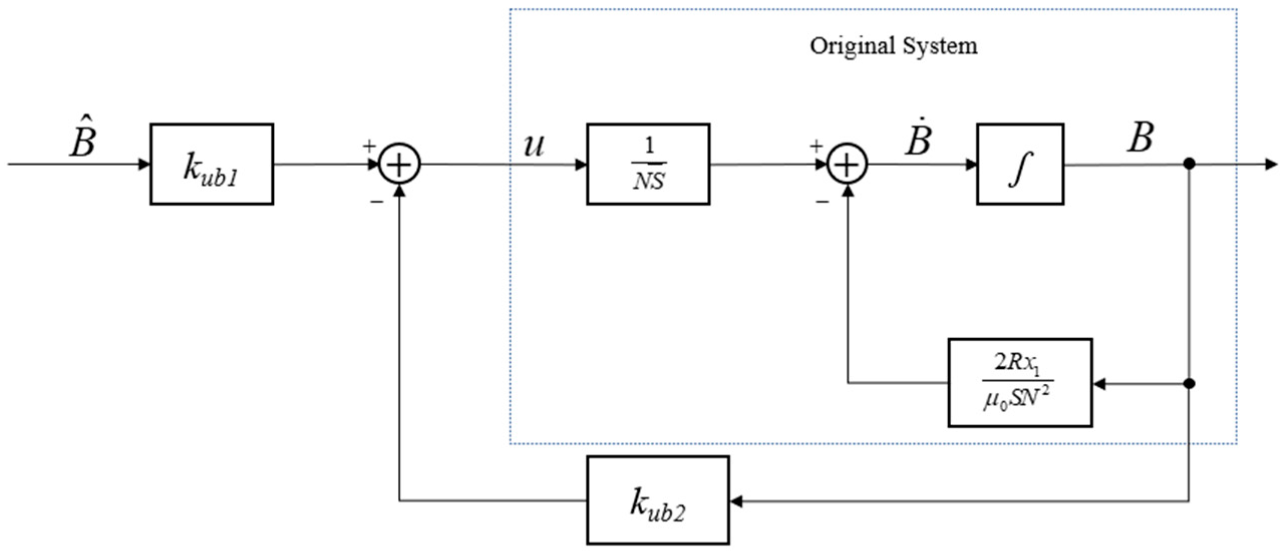
The magnetic flux loop is designed, and this is shown in Figure 4.
The control law can be written in the following form:
u = k u b 1 B ^ k u b 2 B ,
where B ^ is the desired magnetic flux. Substituting Equation (50) into Equation (49), yields
B ˙ = 2 R μ 0 S N 2 x 1 B + k u b 1 B ^ k u b 2 B N S .
Rearranging Equation (51) yields
B ˙ = 2 R μ 0 S N 2 x 1 B + 1 N S u .
Note that B ˙ is related to x 1 in Equation (52), so let
k u b 1 = 2 R x 1 μ 0 N + k u b 2 k u b 2 = k u .
Here, k u is a positive real constant. Substituting Equation (53) into Equation (52), yields
B ˙ = 1 S N 2 R x 1 μ 0 N + k u B ^ B .
By substituting Equation (53) into Equation (48), the control law can be obtained as follows:
u = ( 2 R x 1 μ 0 N + k u ) B ^ k u B B ^ = μ 0 m 1 m 2 k 1 k 2 + 1 e 1 + k 2 x 2 + 2 c 1 k 1 k 2 + 1 k 2 x 4 k 2 x ^ ˙ 1 x ^ ˙ 3 + 2 φ 1 2 x m 1 + m 2 m 2 g S 2 φ 1 2 ( x ) m 1 + m 2 .
Theoretically, the performance of the magnetic flux loop will be better when k u is larger, but actually, the output of the power is limited, so k u should match the power.

3.3. Estimation of the Track State

In an actual maglev system, the vertical displacement and velocity of the track cannot be obtained directly as the train is moving; therefore, the track states need to be estimated in real-time mode. Note that the only state needed in the control law in Equation (46) is the track velocity, so only the track velocity needs to be estimated. According to the definitions of the state variables in the previous section, the vertical acceleration of the electromagnet is a 1 = x ¨ 1 + x ¨ 3 , so the estimation of the track velocity is as follows:
v 3 = x ˙ 3 = a 1 dt x ˙ 1 .
Hence, the states a 1 and x ˙ 1 , which can be obtained by sensors, are used as the inputs of the estimator; because of the existence of the noise and the direct component in the gap signal and the acceleration signal, the signals are filtered by a low-pass filter and an integrator. Then, the estimated value of the track velocity, v 3 , can be obtained as follows:
x ˙ v 1 = λ v 1 x v 1 + λ v 2 x v 2 + a 1 x ˙ v 2 = x v 1 x ˙ v 3 = x v 3 + x ˙ 1 v 3 = λ v 3 x v 1 x v 3 .
Here, λ v 1 , λ v 2 and λ v 3 are positive constants and determine the bandwidth and gain of the estimator. Considering that the control period is 0.00025 s, the parameters of the estimator are chosen as follows: λ v 1 = 5.51257 , λ v 2 = 4.39599 and λ v 3 = 2.12766 ; thus, the noise can be removed in the signal. In this case, the velocity estimator can estimate the vertical velocity of the track with a relatively high speed whilst filtering out the high-frequency noises generated by the accelerometer and the gap sensors.

4. Experimental Verification

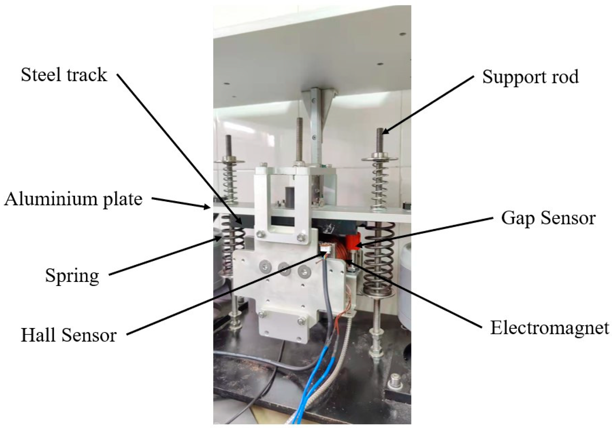
In order to verify the control effect of the designed control scheme, a vehicle–guideway coupled experimental platform with a flexible supported track was designed. Figure 5 shows the basic structure of the experimental platform, which consists of a steel rail, a suspension electromagnet, acceleration sensors and a suspension gap, support springs, two support rods, a power supply, a controller, and so on.
The support rod is fixed in the vertical direction, and the upper and lower springs are fixed along the support rods, supporting the aluminum plate and the rail. There is a groove on the upper surface of the iron core of the electromagnet, and a Hall sensor is placed in this groove to measure the magnetic flux density in the air gap; a gap sensor and an accelerometer are fixed on the electromagnet as well. Compared with the current test and commercial maglev lines in China, the track stiffness and the guideway–vehicle mass ratio of this experimental platform are very low, which makes it easy to produce the vehicle–guideway coupled vibration problem. Therefore, this platform is ideal for studying the vehicle–guideway coupled vibration problem.
Figure 6 shows the photo of the experimental platform. A Hall sensor is installed in the groove to measure the magnetic flux density in the suspension gap. The accelerometer is fixed to the backside of the electromagnet, which cannot be directly seen in this figure. Some relevant parameters of the experimental platform are given in Table 2.
It can be seen that the mass of the track of the experimental platform is only about one third of the mass of the suspension electromagnet, and that the ratio of the mass of the track to the mass of the vehicle is much lower than that of the actual maglev system. For example, the mass per unit length of the guideway and the CMS-04 vehicle shown in Figure 2 are nearly the same, and much larger than this experimental platform. Despite this, self-excited vibration easily occurs when the CMS-04 maglev vehicle passes the girder shown in Figure 2. The smaller the mass ratio, the more likely it is that the coupled vibration of the track will occur; also, it is more difficult for conventional control schemes, such as the PID controller, to achieve stable control.
As a comparison, the effect of the proposed control algorithm discussed above and the state feedback controller based on feedback linearization are both investigated on the designed experimental platform.

4.1. Effect of the State Feedback Controller Based on Feedback Linearization

Feedback linearization is a common method used to deal with control problems in nonlinear systems. The method realizes the accurate linearization of nonlinear systems based on algebraic transformation, which can avoid the systematic error caused by the traditional linear approximation method at the equilibrium point. It can still ensure high accuracy when the system state changes in a large range and has better robustness and reliability.
Let x f 1 = x 1 , x f 2 = x 2 and u f = S B 2 μ 0 m 1 g / μ 0 m 1 , then the state space equation of the single-point suspension system based on feedback linearization can be obtained as follows:
x ˙ f 1 x ˙ f 2 = 0 1 0 0 x f 1 x f 2 + 0 1 u f y = 1 0 x f 1 x f 2 .
and the method of state feedback is used to design the control law, as follows:
B ^ = μ 0 m 1 g + k f 1 x 1 x ^ 1 + k f 2 x 2 S .
Equation (59) shows the expected magnetic flux intensity, and the flux loop is still used in this method. Here, k f 1 and k f 2 are the feedback gains. Then, the state equation of the closed-loop system can be obtained:
x ˙ f 1 x ˙ f 2 = 0 1 k f 1 k f 2 x f 1 x f 2 + 0 1 u f y = 1 0 x f 1 x f 2 .
In this case, the suspension control system is altered to be a second-order linear system whose transfer function is as follows:
G f = 1 s 2 + k f 2 s + k f 1 .
In order to ensure the performance of the closed-loop system, the gain is adjusted so that the real part of the system poles is less than zero. Let k f 1 = 3000 and k f 2 = 50 , then the transfer function has a pair of conjugate poles s 1 , 2 = 25 ± 48.7340 j , which can ensure the stability of the system.
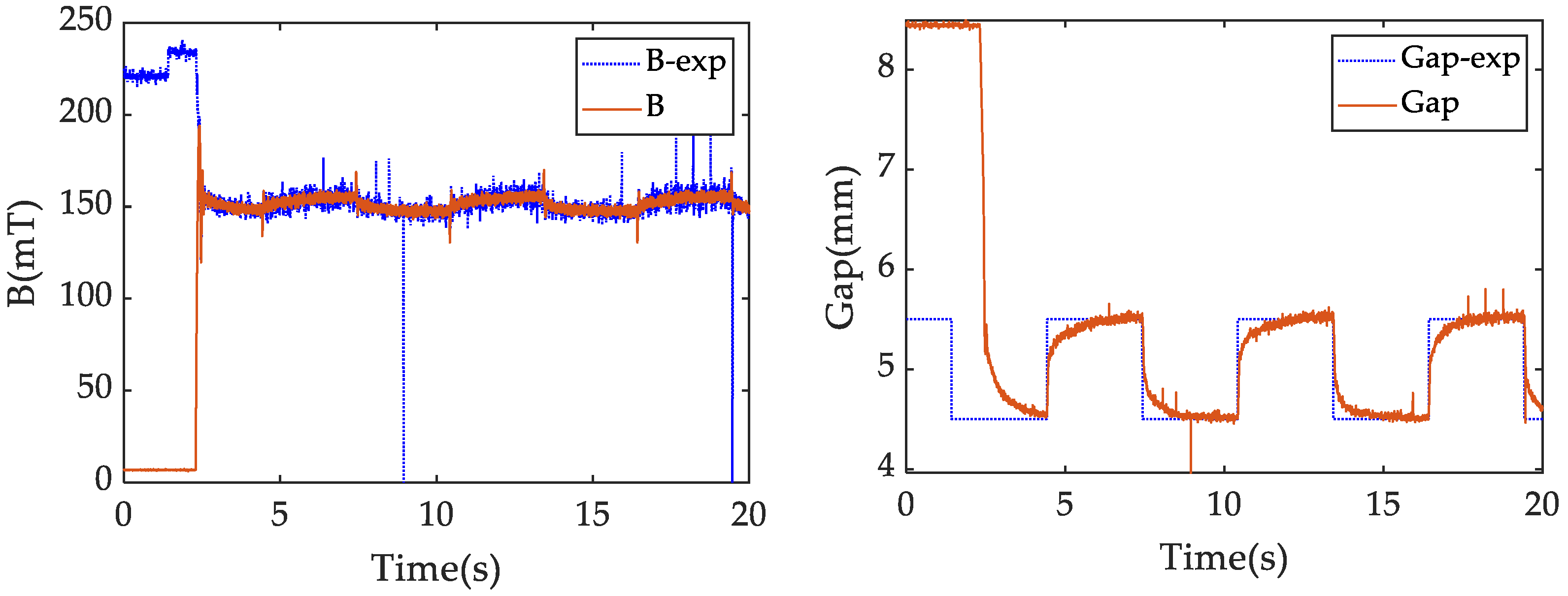
Figure 7 shows the control effect of the state feedback controller based on feedback linearization on the suspension experimental platform when the track is rigid. In this case, extra rods are placed parallel to the springs to support the track, and these serve as rigid constraints to the track and disable the springs from functioning. A square wave signal with an amplitude of ±0.5 mm and a period of 8 s is applied to the desired suspension gap (5 mm). It can be seen that the system can be well stabilized, and that the control effect is satisfactory.
Figure 8 shows the control effect of the state feedback controller based on feedback linearization on the suspension experimental platform when the track is elastic. The parameters are kept unchanged, as listed above. It can be seen that after removing the rigid constraints of the track, the suspension gap begins to oscillate continuously, and the coupled vibration appears. Obviously, the state feedback controller based on feedback linearization could not solve the coupled vibration problem with low track stiffness.

4.2. Effect of the Proposed Backstepping Controller

As a comparison, the method proposed in this paper is also tested under the same conditions presented above. Figure 9 shows the effect of the control scheme proposed in this paper when the track is rigid.
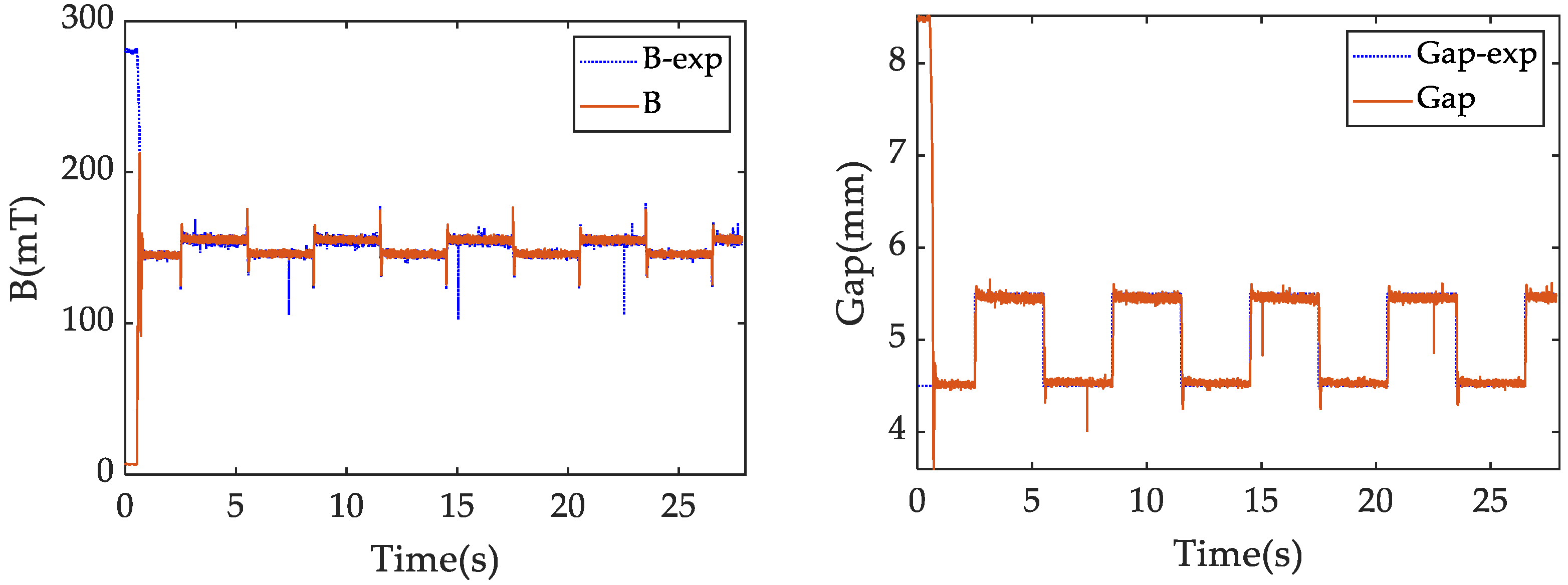
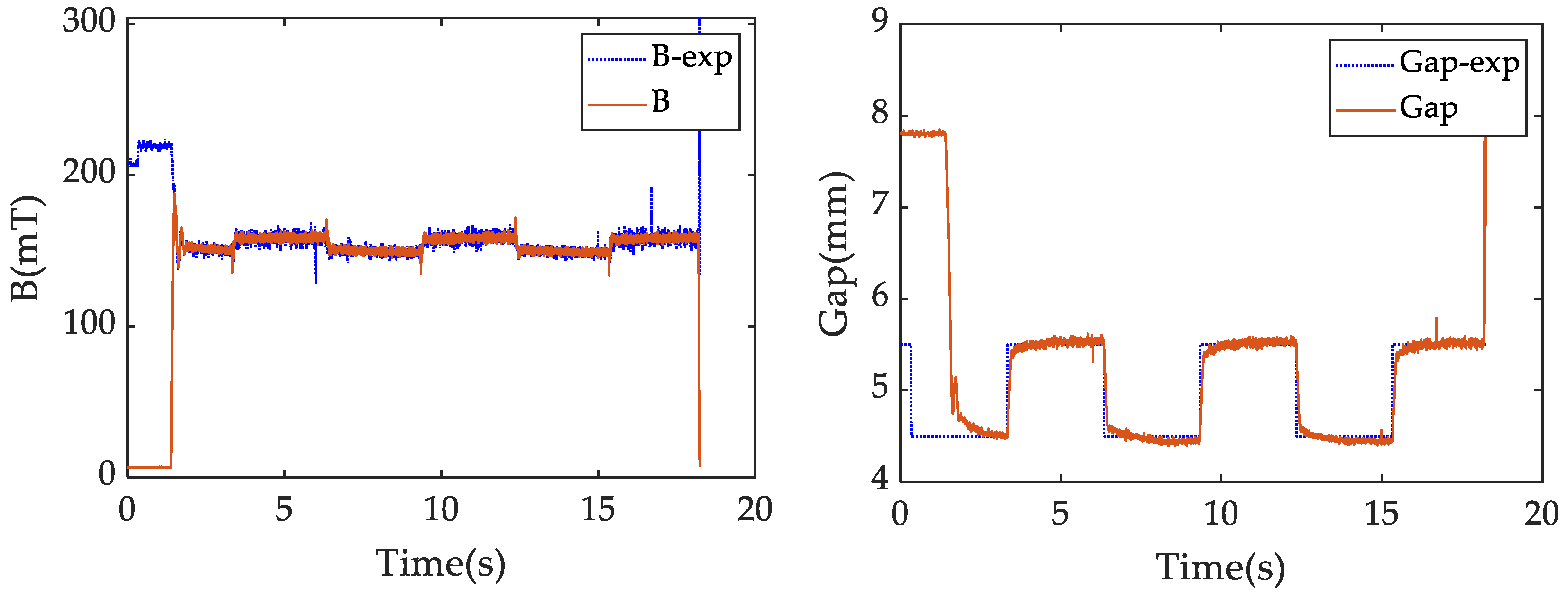
In this figure, B-exp denotes the expected value of the magnetic flux density, B is the actual magnetic flux density measured by the Hall sensor; Gap-exp is the expected suspension gap; and Gap is the actual air gap measured by the gap sensor. Equation (47) shows the relationship between k1 and k2, and their product should be about 6000 when ω 1 2 is about 6000. The maximum output voltage of the power supply is 40, and when k u > 2600 , the output of the power supply cannot not track the expected voltage. Therefore, the control parameters are chosen as follows: k 1 = 25 ,   k 2 = 250 ,   k u = 2600 . The same square wave signal is applied to investigate its control performance. It can be seen that the coupled system is well stabilized, and it appears that the closed-loop system is an over-damped system with no overshoot. Moreover, the tracking speed is fast enough that the square wave signal can be tracked well without vibration. Figure 10 shows the control effect when the track is elastic. It can be seen that the control method can still achieve an excellent control effect.
Figure 11 shows the magnetic flux, the current through the electromagnet, the suspension gap, and the vertical velocity of the track. The vertical velocity of the track is obtained by the state estimator designed in the previous section. It can be seen that, at the beginning of suspension, the current increases rapidly, which quickly increases the electromagnetic force, and it drives the track to move downwards; but after a short period, the track speed is reduced to almost zero. Therefore, it can be concluded that the backstepping control strategy can effectively suppress the vehicle–guideway coupled vibration under the condition of a low-stiffness track.
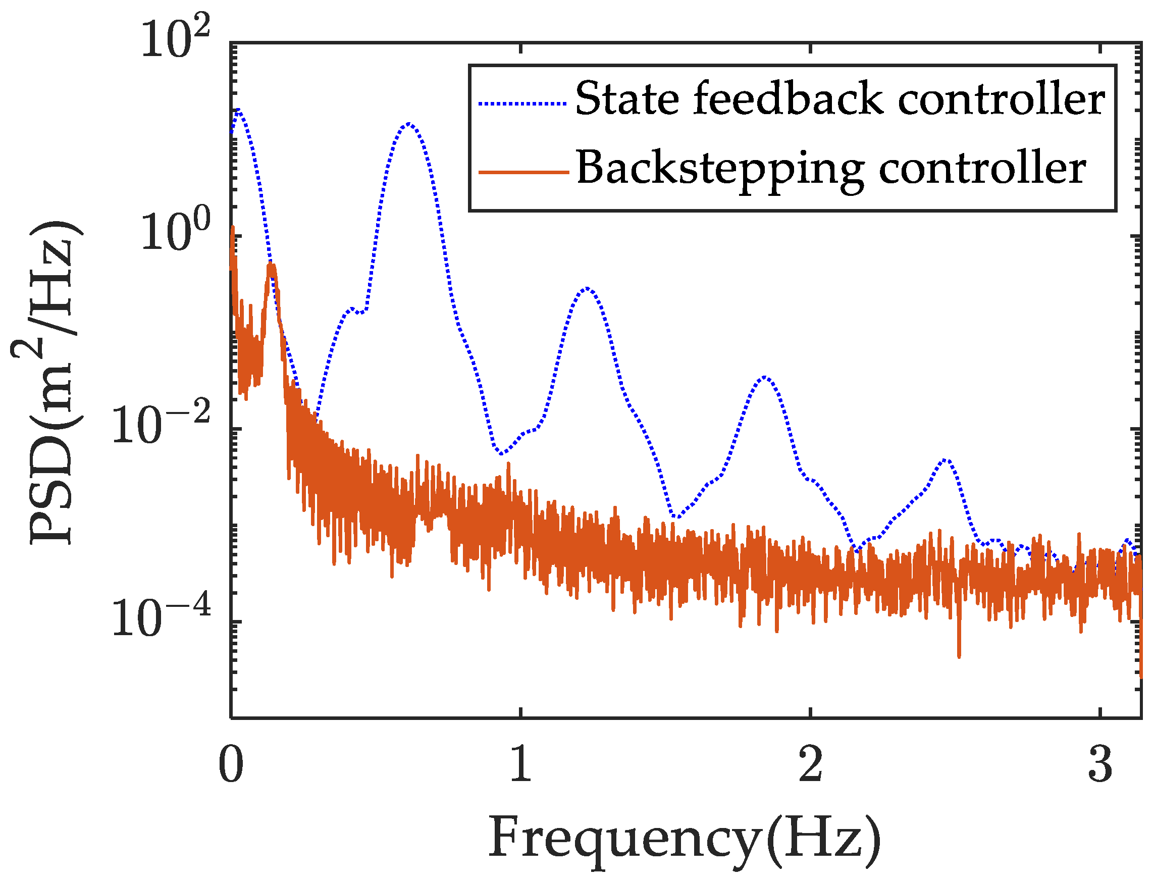
In order to quantify the vibration suppression features, Figure 12 shows the power spectral density (PSD) of the gap error of the backstepping controller and the state feedback controller. And it can be easily seen that the proposed backstepping controller is more able to suppress the vibration of different frequencies than the state feedback controller, especially in the low-frequency band.
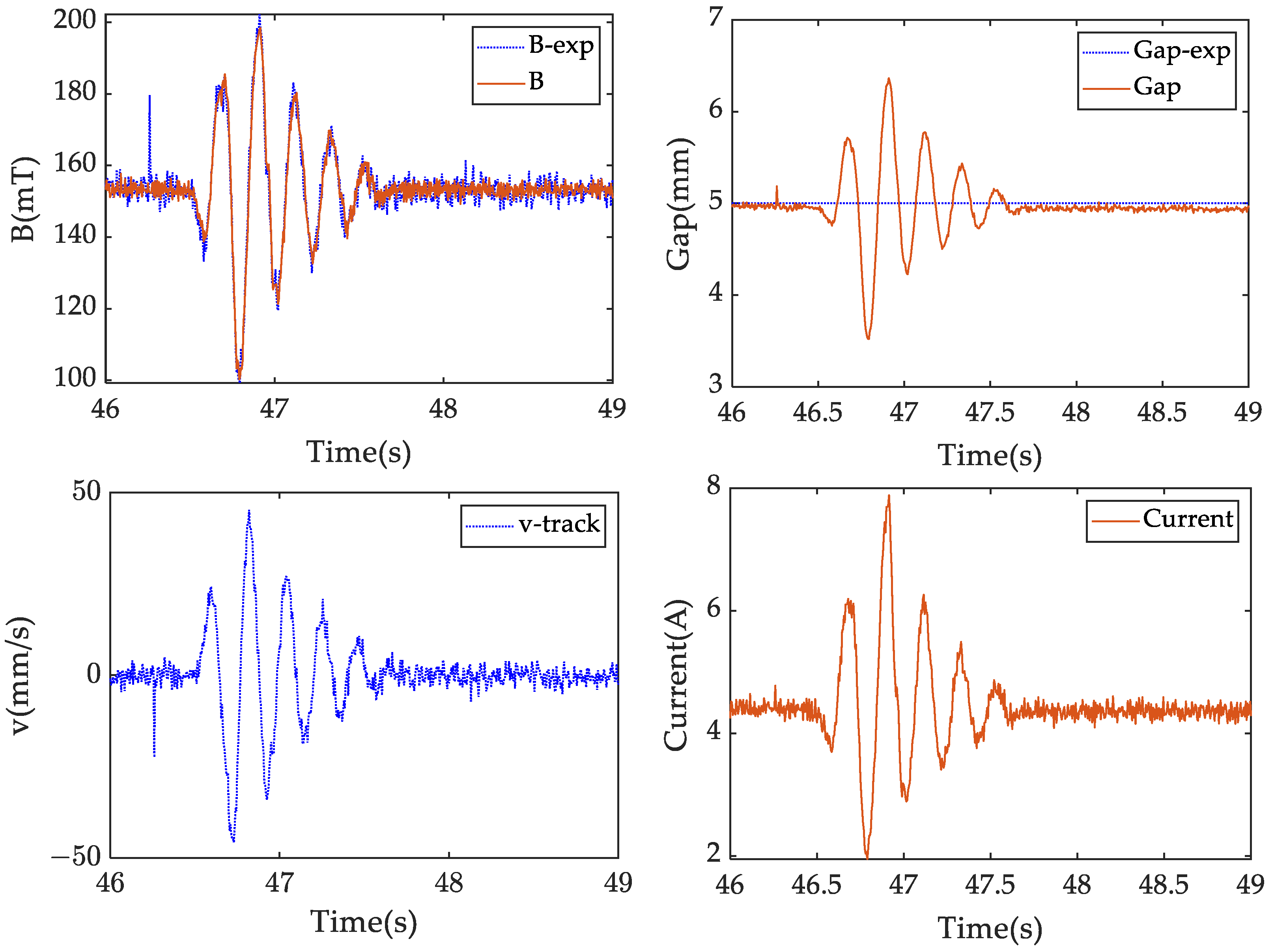
In order to verify the anti-interference ability of the backstepping control strategy, a weight of about 0.15 kg is placed at about 50 mm above the track, and then it is dropped to hit the track, resulting in a sudden external force impulse to the track. The control effect of the system is observed during this process.
Figure 13 shows the magnetic flux, the current through the electromagnet, the suspension gap, the vertical velocity of the track and the current through the electromagnet during the impact. It can be seen that the impact is strong enough to cause the track and the electromagnet to change dramatically. However, after the impact, the oscillation of the suspension gap quickly converges within 1 s. The track velocity also shows a quick attenuation of oscillation. This test indicates that the proposed control strategy can effectively stabilize the vehicle–guideway coupled system, and it shows a good ability to restore the system to the equilibrium position after the system is disturbed. Compared with the traditional control methods, this method has much better stability and anti-disturbance effects. Due to the fact that the track states are taken into account during the process of controller design, the global stability of the system is ensured.

5. Conclusions

In order to solve the maglev vehicle–guideway coupled vibration problem, the theoretical models of the track beam and the suspension system are established. Considering that the magnetic suspension system is highly nonlinear, a suspension control algorithm based on the backstepping method is proposed. Meanwhile, the magnetic flux loop is designed to further improve the stability of the controller. This method does not need to linearize the dynamic model of the coupled system, and its stability can be guaranteed by the Lyapunov stability theory.
This method is experimentally verified on the designed suspension experimental platform, which shows that, compared with traditional control methods, the control scheme proposed in this paper can effectively stabilize the coupled system at a very low rail-to-vehicle mass ratio, and that it also has a good anti-interference abilities at the same time. It is of great significance for suppressing the vehicle–guideway coupled vibration problem.
The control method proposed in this paper can be applied to the EMS maglev train without increasing the hardware cost, and it shows the potential to significantly reduce the cost of track construction.

Author Contributions

Conceptualization, D.Z. and J.L.; methodology, P.Z.; software, T.Z. and Y.J.; validation, P.Z., Q.L. and D.Z.; data curation, T.Z.; writing—original draft preparation, P.Z.; writing—review and editing, D.Z. and P.Z. All authors have read and agreed to the published version of the manuscript.

Funding

This work is supported by National Key R&D Program of China [grant number 2016YFB1200601], and the Major Project of Advanced Manufacturing and Automation of Changsha Science and Technology Bureau under grant number kq1804037.

Data Availability Statement

Data are contained within the article.

Conflicts of Interest

The authors declare no conflicts of interest.

References

  1. Lee, H.; Kim, K.; Lee, J. Review of maglev train technologies. IEEE Trans. Magn. 2006, 42, 1917–1925. [Google Scholar]
  2. Yan, L. Development and application of the maglev transportation system. IEEE Trans. Appl. Supercon. 2008, 18, 92–99. [Google Scholar]
  3. Wang, S.-M.; Wang, Y.-W.; Ni, Y.-Q.; Lu, Y. Real-Time Malfunction Detection of Maglev Suspension Controllers. Mathematics 2023, 11, 4045. [Google Scholar] [CrossRef]
  4. Sun, Y.; Xu, J.; Chen, C.; Hu, W. Reinforcement learning-based optimal tracking control for levitation system of maglev vehicle with input time delay. IEEE Trans. Instrum. Meas. 2022, 71, 7500813. [Google Scholar] [CrossRef]
  5. Tian, X.; Xiang, H.; Chen, X.; Li, Y. Dynamic response analysis of high-speed maglev train-guideway system under crosswinds. J. Cent. South Univ. 2023, 30, 2757–2771. [Google Scholar] [CrossRef]
  6. Kim, K.; Han, J.; Han, H.; Yang, S. Coupled vibration analysis lysis of maglev vehicle–guideway while standing still or moving at low speeds. Veh. Syst. Dyn. 2015, 53, 587–601. [Google Scholar] [CrossRef]
  7. Li, L.; Meng, G. Analysis of the maglev vehicle and steel guideway frame coupled resonance during levitating up and landing. J. Vib. Shock 2006, 25, 46–48+75. [Google Scholar]
  8. Zhou, D.; Li, J.; Hansen, C.H. Suppression of the stationary maglev vehicle-bridge coupled resonance using a tuned mass damper. J. Vib. Control 2013, 19, 192–203. [Google Scholar] [CrossRef]
  9. Wang, D.; Li, X.; Liang, L.; Qiu, X. Influence of the track structure on the vertical dynamic interaction analysis of the low-to-medium-speed maglev train-bridge system. Adv. Struct. Eng. 2019, 22, 2937–2950. [Google Scholar] [CrossRef]
  10. Zeng, J.; Xia, W.; Xiang, X.; Long, Z. Research on the mechanism and control characteristics of vehicle-track beam coupled vibration for medium-speed maglev vehicle. IEEE Trans. Transp. Electr. 2022, 8, 3236–3246. [Google Scholar] [CrossRef]
  11. Zhang, M.; Luo, S.; Gao, C.; Ma, W. Research on the mechanism of a newly developed levitation frame with mid-set air spring. Veh. Syst. Dyn. 2018, 56, 1797–1816. [Google Scholar] [CrossRef]
  12. Li, J.H.; Li, J.; Zhou, D.; Wang, L. Maglev self-excited vibration suppression with a virtual sky-hooked damper. J. Cent. South Univ. 2016, 23, 1363–1371. [Google Scholar] [CrossRef]
  13. Song, R.; Chen, Z. Optimization and design of maglev system PID controller based on particle swarm optimization algorithm. J. Southwest Jiaotong Univ. 2015, 50, 36–43. [Google Scholar]
  14. Wang, B.; Zhang, Y.; Xia, C.; Li, Y.; Gong, J. Dynamic analysis of high-speed maglev train-bridge system with fuzzy proportional-integral-derivative control. J. Low Freq. Noise Vib. Act. Control. 2022, 41, 374–386. [Google Scholar] [CrossRef]
  15. Adil HM, M.; Ahmed, S.; Ahmad, I. Control of maglev system using supertwisting and integral backstepping sliding mode algorithm. IEEE Access 2020, 8, 51352–51362. [Google Scholar] [CrossRef]
  16. Alain KS, T.; Fabien, K.; Martin, S.S.; Bertrand, F.H. Robust nonsingular sliding mode control of the maglev train system: Case study. SN Appl. Sci. 2021, 3, 2523–3963. [Google Scholar] [CrossRef]
  17. Ni, F.; Mu, S.; Kang, J.; Xu, J. Robust controller design for maglev suspension systems based on improved suspension force model. IEEE Trans. Transp. Electr. 2021, 7, 1765–1779. [Google Scholar] [CrossRef]
  18. Sun, Y.; Xu, J.; Lin, G.; Sun, N. Adaptive neural network control for maglev vehicle systems with time varying mass and external disturbance. Neural Comput. Appl. 2021, 35, 12361–12372. [Google Scholar] [CrossRef]
  19. Chen, C.; Xu, J.; Lin, G.; Sun, Y.; Ni, F. Model identification and nonlinear adaptive control of suspension system of high-speed maglev train. Veh. Syst. Dyn. 2022, 60, 883–905. [Google Scholar] [CrossRef]
  20. Chen, X.; Zhang, Q.; Liu, J. Extended State Observer-Based Saturation Integral Backstepping Control for Yaw Control of UAV Helicopters. In Proceedings of the Advances in Guidance, Navigation and Control, Shanghai, China, 5–7 November 2021; pp. 4021–4037. [Google Scholar]
  21. Choi, Y.; Lee, I.; An, J.; Cho, M.; Kim, C. Robust trajectory-tracking control of a rotorcraft using immersion-and-invariance-based adaptive backstepping control. Int. J. Aerosp. Eng. 2022, 2022, 8447125. [Google Scholar] [CrossRef]
  22. Gao, M.; Jin, X.; Ding, L. Robust adaptive backstepping INTSM control for robotic manipulators based on ELM. Neural Comput. Appl. 2022, 34, 5029–5039. [Google Scholar] [CrossRef]
  23. Malik, A.S.; Ahmad, I.; Rahman, A.U.; Islam, Y. Integral backstepping and synergetic control of magnetic levitation system. IEEE Access 2019, 7, 173230–173239. [Google Scholar] [CrossRef]
  24. Yaseen HM, S.; Siffat, S.A.; Ahmad, I.; Malik, A.S. Nonlinear adaptive control of magnetic levitation system using terminal sliding mode and integral backstepping sliding mode controllers. ISA Trans. 2021, 126, 121–133. [Google Scholar] [CrossRef] [PubMed]
  25. Xu, J.; Sun, Y.; Gao, D.; Ma, W.; Luo, S.; Qian, Q. Dynamic modeling and adaptive sliding mode control for a maglev train system based on a magnetic flux observer. IEEE Access 2018, 6, 31571–31579. [Google Scholar] [CrossRef]
  26. Zhang, W.; Li, J.; Zhang, K.; Cui, P. Measurement and control of magnetic flux signal in a maglev system. Asian J. Control 2015, 17, 165–175. [Google Scholar] [CrossRef]
  27. Wang, L.; Zhou, D.; Yu, P.; Chen, Q.; Li, J.; Li, J.H. Research on maglev train-steel beam coupling vibration suppression strategy based on flux derivative feedback. In Proceedings of the 39th Chinese Control Conference, Shenyang, China, 27–29 July 2020; pp. 5637–5642. [Google Scholar]
  28. Zhou, D.; Yang, Q.; Wang, L.; Li, J. Stability and control of maglev vehicle-girder coupled system considering torsional vibration of the girder. ISA Trans. 2021, 111, 309–322. [Google Scholar] [CrossRef]
Figure 1. A cross-section of the simplified single-point suspension structure.
Mathematics 12 02134 g001
Figure 2. The maglev vehicle and the elevated guideway.
Mathematics 12 02134 g002
Figure 3. Simplified model of the maglev vehicle–guideway system.
Mathematics 12 02134 g003
Figure 4. Block diagram of the magnetic flux loop.
Mathematics 12 02134 g004
Figure 5. Simplified structure of the experimental platform.
Mathematics 12 02134 g005
Figure 6. Diagram of the actual components of the maglev vehicle–guideway experimental platform.
Mathematics 12 02134 g006
Figure 7. Control effect of the state feedback controller based on feedback linearization under the rigid track conditions (kf1 = 3000, kf2 = 50).
Mathematics 12 02134 g007
Figure 8. Control effect of the state feedback controller based on feedback linearization under the elastic track conditions (kf1 = 3000, kf2 = 50).
Mathematics 12 02134 g008
Figure 9. Control effect of the backstepping controller under the rigid track conditions.
Mathematics 12 02134 g009
Figure 10. Control effect of the backstepping controller under the elastic track conditions.
Mathematics 12 02134 g010
Figure 11. The magnetic flux, suspension gap, vertical track velocity and control current during the process of suspending.
Mathematics 12 02134 g011
Figure 12. The power spectral density (PSD) of the gap error of the backstepping controller and the state feedback controller.
Mathematics 12 02134 g012
Figure 13. The magnetic flux, control current, suspension gap, and vertical track velocity during the weight impact experiment.
Mathematics 12 02134 g013
Table 1. System parameters of the simplified single-point suspension structure.
ParameterDefinition
z1Air gap between the track and the suspension electromagnet
m1Mass of the suspension electromagnet
FeElectromagnetic force between the electromagnet and the track
fd1External disturbance force
uVoltage applied to the electromagnet winding
BMagnetic flux density in the suspended air gap
iCurrent through the winding
NNumber of turns of the electromagnet
SPole area of the electromagnet
μ 0 Vacuum permeability
WWork done by the electromagnetic force on the electromagnet
RResistance on the winding
FmMagneto-motive force
R m Resistance of the electromagnet
ϕ 1 Air gap magnetic flux
gGravitational acceleration
Table 2. System parameters of the experimental platform.
ParameterDefinitionValue
m1Mass of the levitation electromagnet7.40 kg
m2Mass of track2.66 kg
RWinding resistance3.3 Ω
NNumber of turns of the winding830
SPole area0.001 m2
Disclaimer/Publisher’s Note: The statements, opinions and data contained in all publications are solely those of the individual author(s) and contributor(s) and not of MDPI and/or the editor(s). MDPI and/or the editor(s) disclaim responsibility for any injury to people or property resulting from any ideas, methods, instructions or products referred to in the content.