Abstract
This paper studies the path planning problem for aircraft fleet taxiing on the flight deck of carriers, which is of great significance for improving the safety and efficiency level of launching. As there are various defects of manual command in the flight deck operation of carriers, the establishment of an automatic path planner for aircraft fleets is imperative. The requirements of launching, the particularities of the flight deck environment, the way of launch, and the work mode of catapult were analyzed. On this basis, a mathematical model was established which contains the constraints of maneuverability and the work mode of catapults; the ground motion and collision detection of aircraft are also taken into account. In the design of path planning algorithm, path tracking was combined with path planning, and the strategy of rolling optimization was applied to get the actual taxi path of each aircraft. Taking the Nimitz-class aircraft carrier as an example, the taxi paths of aircraft fleet launching was planned with the proposed method. This research can guarantee that the aircraft fleet complete launching missions safely with reasonable taxi paths.
1. Introduction
The aircraft carrier battle group is a symbol of maritime supremacy, and plays an irreplaceable role in both defending the security of territorial waters and safeguarding maritime interests [1,2]. It is important to ensure the normal operation of aircraft carrier platforms in complicated conditions; this has a critical influence on enhancing the fighting capacity of the carrier-carrier aircraft system [3]. As the area of flight deck is limited, aircraft must be well prepared before they can launch and enter combat in the air. As the number of aircraft parking on the flight deck is increasing, an important and difficult problem is to make the flight operations in good order, i.e., launching and landing safely and efficiently [4,5]. Therefore, it is of great significance to develop an automatic planner to organize aircraft launching with optimized taxi paths on the space-limited and resource-limited flight deck of the carrier.
At present, the taxi of aircraft mainly relies on the manual command on the flight deck: a commander sends instructions regarding the taxiing direction to the pilot, and the pilot in the aircraft follows the instructions and manipulates the actuators to drive the aircraft to the destination. When the flight deck is empty and other aircraft are parking, this work mode is feasible, but there are still two defects. Firstly, it has negative effects on the safety of staff working on the flight deck, i.e., they may be struck by the taxiing aircraft, sucked into the intake of aircraft, and so on [6]. The optimality of the taxiing path still cannot be ensured. In a combat mission, there are a certain number of aircraft waiting to launch on different catapults. On this occasion, several aircraft will taxi onto the flight deck simultaneously, and it is difficult for the manual command to cope with the complicated situation and make a reasonable plan. In view of the above defects of manual command, an automatic path planner for aircraft fleet taxiing task is imperative to enhance safety and efficiency.
In the existing literature, the studies on flight deck operations of aircraft mainly focus on the launching and landing capacity of aircraft fleet, schedule for aircraft fleet launching, and path planning for a single taxiing aircraft. When analyzing the launching and landing capacity of aircraft fleets, the efficiency of launching or landing is regarded as the optimization goal [7], which is usually denoted by the number of aircraft launching or landing in specific time interval. It is a good way to treat different preparation tasks before launching as different states, and the state transition is equivalent to the handover between different preparation tasks. On this basis, the state transition map is used to analyze the maintenance and operations on the flight deck [8]. As for the air traffic management of returning aircraft, a stock-flow model is established. In this model, the traffic flow in the air can be predicted on the condition that the bolting and the wave-off are considered in failed-to-land aircraft, which ensures that the flow of aircraft can adapt to the capacity of airspace in each stage [9].
In the scheduling for aircraft launching, the goal is to minimize the total time consumption and the taxiing length of aircraft fleet, and the scheduling can be transformed into an optimization problem with multiple objectives under certain constraints. An effective way of solving the problem is to search for the optimal launching plan by changing the launching orders in different parking positions [10,11]. As several steps, i.e., taxiing, preparation on catapult, and launch must be finished before the aircraft can leave for combat in the air, a sensitivity analysis is conducted on each step, and the main factors influencing the launching efficiency can be obtained and improved [12]. Unmanned aerial vehicles (UAVs) have been introduced onto carriers, and the command mode for the mixed manned and unmanned aircraft fleets also makes a big difference in terms of launching efficiency [5].
In the field of path planning for a single aircraft taxiing on the flight deck, the modeling of flight deck environment and the design of path search algorithms are most important. The shape of aircraft is an irregular polygon, and simplification is needed to reduce the computation load and ensure that the aircraft can avoid the obstacles. The usual ways are to simply think of the aircraft as a particle and expand the boundaries of obstacle. With this strategy, the obstacle detection problem transforms into judging whether a point is in the area enclosed by the expanded boundaries of obstacle; thus, the computation is reduced [13,14]. In terms of path planning algorithm design, the improvements on the existing algorithms are often adopted to meet the special requirement of a given taxiing task. Another hot spot is to combine the advantages of several algorithms. By those operations, the local optimum is avoided, and the convergence rate is improved [15].
In summary of the current studies on scheduling for aircraft launching, determination of a launching plan and path planning for a single aircraft are active. However, after the launching plan is decided, each aircraft must taxi to the appointed catapult, and no study on path planning for multiple aircraft taxiing on flight deck simultaneously has been undertaken. This paper studies path planning for aircraft fleet launching on the flight deck of carriers with limited space and resources, according to the determined launching plan. Firstly, a mathematical model is established which contains the constraints of maneuverability, the work mode of catapults, ground motion, and collision detection of aircraft taxiing on flight deck. The optimization goal is to minimize the total time consumption of aircraft fleet launching. To obtain the taxiing path for each aircraft directly, path tracking is combined with path planning in the algorithm design, and a real-time collision detection method is proposed to ensure the safety of each path. Finally, the actual taxi paths of aircraft fleets are generated with the proposed path planning method.
2. Establishment of Mathematical Model
2.1. Constraints of Aircraft Taxiing on the Flight Deck
Here, the ground performance and the ground motion of aircraft are considered. The ground motion model of aircraft can be consulted in Ref. [15], and the ground maneuver performance will be explained next. We define as the minimum straight path length to make the aircraft not turn frequently, and as the maximum angle to make the aircraft turn within its maneuverability. To sum up the above preparations, the matrix is used to express the ground maneuver performance of the carrier aircraft, where j = 1 and j = 2 represent the performance of and respectively. The model can be used to determine the position of spare path point in the path planning algorithm.
Additionally, each aircraft of the fleet executes its own launching task according to the command of mission planning system [16]. The constraints of launching task are shown in Table 1.

Table 1.
Constraints of launching task.
In Table 1, Dmax limits the turning frequency which results in a more satisfactory path. v limits the taxi velocity of carrier aircraft. In addition, guarantees the aircraft reach the destination with a specified angle and finish the task smoothly.
2.2. Work Model of the Catapult
To ensure the safety of launching, the aircraft must reach the assigned catapults one by one. If two aircraft prepare to launch from the same catapult successively, the latter is prohibited from starting until the former finishes launching to avoid crowdedness or collisions [17]. We define and as the start and end time of launching from Ai to Cj respectively, where p is the serial number of aircraft launching at Cj; q is the serial number of aircraft in the launching fleet, and they meet . The constraint is denoted as follows:
where is an integer; is a positive integer and they meet the constraints of and .
2.3. Model of Launching Time Interval
Under normal circumstances, the first-come-first-served basis is applied to the aircraft-catapult system. However, the vortex flow produced by a carrier aircraft launching may have a bad influence on the next one [18]. Therefore, the next one which has reached the catapult needs to wait until the influence has reduced for safety reasons. The mathematical model of the vortex flow dissipation is presented as follows [19]:
where is the intensity of vortex flow at moment ; is the moment that the vortex flow keeps its initial intensity. When the threshold of vortex flow is given, it means that the carrier aircraft launching is no longer affected by the vortex flow when . From Equation (2) we can get the influence time of vortex flow, which is defined as Tvortex:
Therefore, the time interval of two consecutive aircraft launching at different catapults meet the following constraint:
where and are integers and they meet the constraints of and . Exceptionally, if the catapult from which the former carrier aircraft launches is behind the one from which the latter launches, Equation (4) needn’t be met, because the influence of the vortex flow can be ignored in this case.
Another aspect which must be borne in mind is that each aircraft spends approximately the same amount of time preparing for launching on the catapult, during which it expands its folding wings, connects with the catapult, and waits to launch. Therefore, we denote this period as Tpre.
2.4. Simplified Model and Collision Detection Model for Aircraft
When considering collision between aircraft, the aircraft cannot be treated as a particle. In view of the fact that the folding wings are applied when the aircraft taxis on the flight deck, the aircraft is simplified as a zygomorphic pentagon, which is similar with its actual shape, as shown in Figure 1.
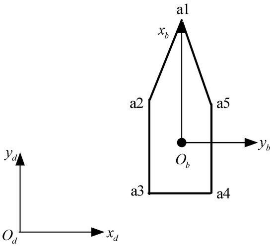
Figure 1.
Diagram of simplified model of carrier aircraft.
In Figure 1, the flight deck axis system and the body axis system are built. The center of the pentagon is , which represents the location information of aircraft, the angle represents the nose of aircraft, and the straight line represents the taxi direction of aircraft. When determining the location and the taxi direction of aircraft in the flight deck axis system , the coordinates of (expressed as in the deck axis system) and the angle (rotates from the axis to the axis in clockwise direction) need to be known. Eventually, the coordinates of any point in the flight deck axis system can be obtained with Equation (5) according to the coordinates in the body axis system and the transition matrix (Equation (6)) from the body axis system to the flight deck axis system.
As the aircraft is simplified to a zygomorphic pentagon, the collision detection problem between the aircraft is turned into a problem of geometric intersection detection between two pentagons. This paper adopts the method of ‘side to side’ intersection detection, i.e., that each side of pentagon a is detected against every side of pentagon b respectively, as shown in Figure 2.

Figure 2.
Diagram of collision detection model for aircraft. In case (a), the two aircraft collide with each other, and in case (b), the two aircraft are both safe.
2.5. Establishment of Objective Function
According to the work model of the catapult and the model of launching time interval, each aircraft undergoes four phases, i.e., waiting to start, taxiing to catapult, waiting for launching, and launching before it finishes the task. We assume the time of each phase above is , , and respectively, and the total task time is for each carrier aircraft. Therefore, we can get:
where meets , which indicates that the waiting time before launching is the maximum between the preparation time and the remaining influence time of vortex flow. In Equation (7), each item is related to the taxi time and needs to be optimized, except for . In order to formulate the starting moment of the first batch of aircraft as the initial time, we establish the optimization index, which is subject to constraints, as follows:
where is the optimization index, i.e., the total time consumption of the fleet during the whole launching process.
3. Path Planning Algorithm
In the previous section, the mathematical model was established. Now an effective path planning algorithm is needed to generate the taxi path for each aircraft. The existing literature makes the path feasible by modifying it with a geometric method, like B-Spline curve, polynomial fitting, and so on [20,21]. It’s a two-step process to get the feasible path, and cannot guarantee that the path meets the constraints of maneuverability. Therefore, the path tracking is combined with the path planning in this paper, and the obtained path segment is tracked immediately when the expansion of path node finishes in each step.
When designing the path search algorithm, a real-time collision detection method is proposed based on the A* algorithm. Not only the constraints of a single aircraft are considered, but also collision detection is executed multiple times in each step of the path search to ensure the safety of each path.
Aiming at the planned path, path tracking is converted to the parameter optimization problem based on the parameterization of control variables. The receding horizon control method is applied to transform the parameter optimization in a fixed time domain into the rolling optimization, which optimizes the performance index of path tracking and reduces the error of path tracking.
3.1. Design of the Search Algorithm
This mainly focuses on the expansion of path node, the design of heuristic function, and the execution of collision detection method. Next, these notions will be introduced.
3.1.1. A*-Based Path Planning Algorithm
The cost function A* algorithm adopts is [22,23]:
where g(x) is the true cost from the starting point to the current node x; h(x) is the heuristic function which denotes the estimated cost from the current node x to the destination. The spare node which minimizes f(x) will be the next path point in each step of expansion. When expanding the path node, the search space can be narrowed and the search accuracy can be improved by integrating various constraints into the search algorithm. A detailed explanation is given in Ref. [23].
The selection of heuristic function h(x) plays a vital role in determining the path points. This paper designs a piecewise dynamic weight heuristic function reasonably according to the flight deck environment and the task requirements. What’s more, the shortest path meeting the direction of reaching the destination is ensured by modifying the weight of each item in h(x) dynamically according to the distance from the carrier aircraft to the destination. h(x) can be expressed as follows:
where l(x) is the distance from the spare node to the destination; is a constant which makes each item have the same order of magnitude so as to identify the importance of each intuitively; i is the serial number of the current node; angle(x) describes the direction of reaching destination; vio is the degree of violation which is set to when a collision occurs and otherwise; p(x) is the distance from the current node to the spare node and q(x) is the distance from the spare node to the destination. What calls for special attention is that the spare nodes must meet the direction of reaching the destination firstly when ; then the values of h(x) can be calculated. The design of h(x) pays different attention to each item according to the distance between the spare node and the destination.
3.1.2. Collision Detection Method
When expanding the path node, it must be confirmed whether collision will occur between the spare node and other parking or taxiing aircraft. Specifically, only when two or more pentagons have an overlapping part do we set to abandon the spare node; otherwise, we set . The process of collision detection is shown in Figure 3.
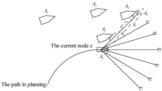
Figure 3.
Diagram of the collision detection.
In Figure 3, A5 is expanding its path node, and A1, A2, A3, and A4 are the aircraft parking or taxiing on the flight deck. As for A5, m locations (in Figure 1, m = 3) of aircraft whose boundary is represented with the dotted borders are selected evenly in each spare path segment to execute collision detection with A1, A2, A3, and A4 respectively. Only when all of the m locations pass the collision detection test do we set ; otherwise, we set . The above strategy executes the collision detection test multiple times in each step of path search, and collisions are avoided.
3.2. Rolling Optimization Method for Path Tracking
After finishing an expansion of the path node, the aircraft tracks the obtained path using the ground motion equations. Then, a series of path tracking instructions are generated to guide the aircraft taxi along the planned path with minimal deviation. The main idea of path tracking is presented as follows.
When the terminal conditions of tracking the obtained path are met, the actual location of the aircraft is regarded as the current node x, and the process of expanding the path node continues until the ultimate terminal conditions of path tracking is met.
The state information of aircraft at a sampling time can be obtained from the ground motion model of aircraft. The controlled variable (deflection of nose wheel of landing gear) is discretized within its range at any given moment k, and the possible state of aircraft at moment k + 1 can be obtained. Then, according to the performance index of path tracking, the state of aircraft at moment k + 1 can be determined. In this way, the state of aircraft at any sampling time can be obtained, as shown in Figure 4.

Figure 4.
Diagram of discretizing the controlled variables.
In this situation, the goal of path tracking is to guide the aircraft to the right catapult to launch. Considering that multiple aircraft are taxiing on the flight deck at the same time, the taxi time which the aircraft spends on each path segment must be strictly limited to guarantee the safety. Therefore, the essence of the path tracking problem in this paper is that the actual path points must track the planned path in chronological order, where the track object is a straight line between the actual path point and the point in the planned path at time point i. Figure 5 is the diagram of path tracking.
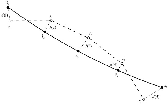
Figure 5.
Diagram of path tracking.
In Figure 5, the thick dotted line represents the path to be tracked, while the hollow dot represents the state of aircraft at time point i; the solid line represents the actual taxi path and the solid dot represents the actual state of aircraft at time point i; the tracking error d(i) at time point i is represented by the thin dashed line. In a real situation, the aircraft must track the planned path strictly according to chronological order.
The performance index of path tracking always evaluates the state of aircraft for some time based on the requirement of rolling optimization [24]. Therefore, the performance index is constructed with the minimum deviation between the predicted state and the known state in the planned path.
Firstly, the deviation between the predicted location and the known location in the planned path is examined. The state information of aircraft at any time in the future can be obtained by the ground motion model with the initial state and control variable at the initial moment k. Then, the error of path tracking at the moment k + i is defined as the straight length between the predicted location and the corresponding point in the planned path, and the average tracking error in the planning domain is regarded as the first item of performance index, which can be expressed as follows after normalization:
where TC is the time of planning domain, and dmax is the maximum tracking error permitted.
In addition, the deviation at the end of the planning domain, , and the lateral tracking deviation, , should also be examined, which can be expressed as follows after normalization:
where is the maximum tracking error of path angle permitted.
To sum up, the performance index of the path tracking can be expressed as follows:
where , and are the weights to reflect the relative importance among different items of the performance index.
In each step of path tracking, the control sequence which minimizes the performance index K is selected as the optimal control sequence in the planning domain TC. Furthermore, the control domain Te is introduced to decide the optimal control sequence which is executed; that is to say, the elements from the optimal control sequence are regarded as the actual optimal control instruction to act on the nose wheel of landing gear and finish one step of path tracking.
3.3. Procedure of the Path Planning Algorithm
The contents of the path planning algorithm are described in the above chapters. Assuming that the number of aircraft is N, now the flow chart is used to represent the steps of path planning, as shown in Figure 6.

Figure 6.
Flow of the path planning algorithm.
4. Experimental Results
Next, the launching mission of 14 aircraft on the flight deck is taken as an example, and the taxi path for each aircraft is planned with the proposed method under the simulation environment of Windows 7 (from Microsoft Corporation, Washington, United States) and Matlab (ver R2009a, from The MathWorks, Massachusetts, United States). The taxi path, time parameters and state information of each aircraft are presented to demonstrate the validity of proposed method.
4.1. Model and Parameters of Experiments
In the Nimitz-class carrier, there are 14 parking aircraft waiting for launching. The diagram of the model and the parameter settings are shown in Figure 7 and Table 2.
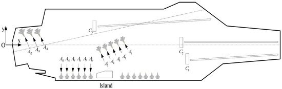
Figure 7.
Diagram of experiment model.
Table 2.
Parameters setting in the experiment.
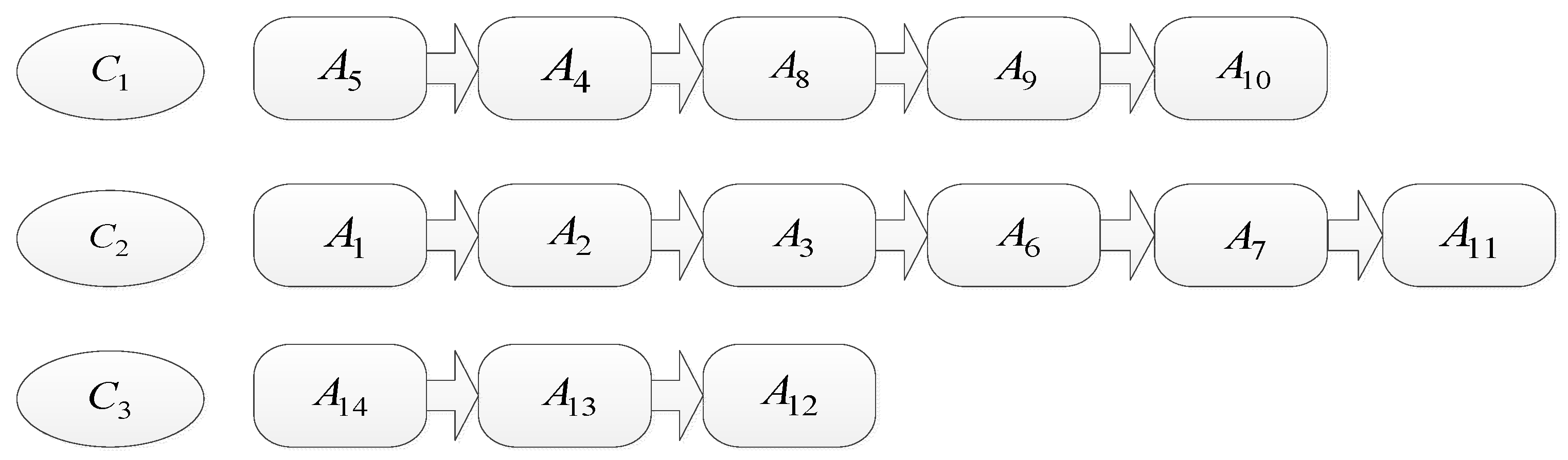
In addition, the mission planning system sends the launch plan to the fleet as shown in Figure 8. For example, the launching sequence at C1 is A5, A4, A8, A9 and A10.

Figure 8.
The schedule of launching mission.
4.2. Simulation Results
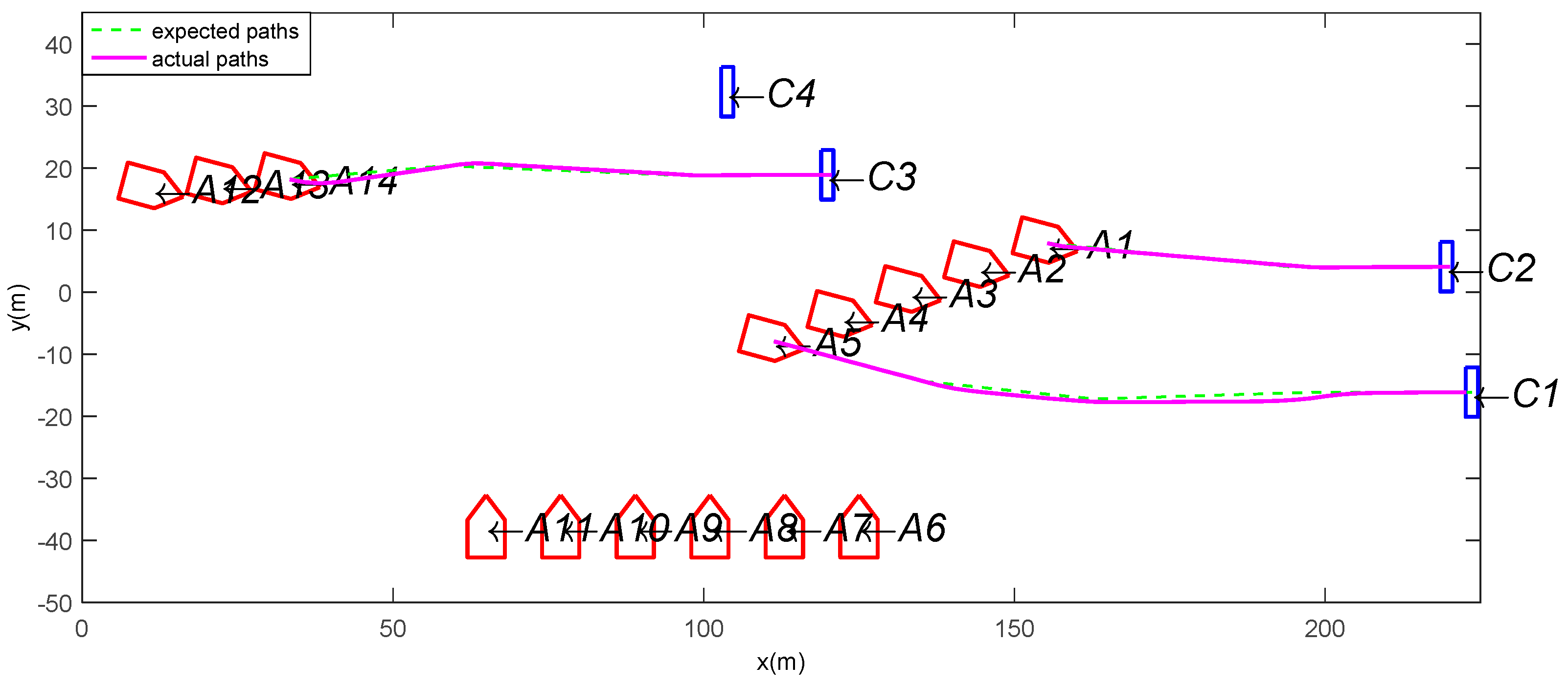
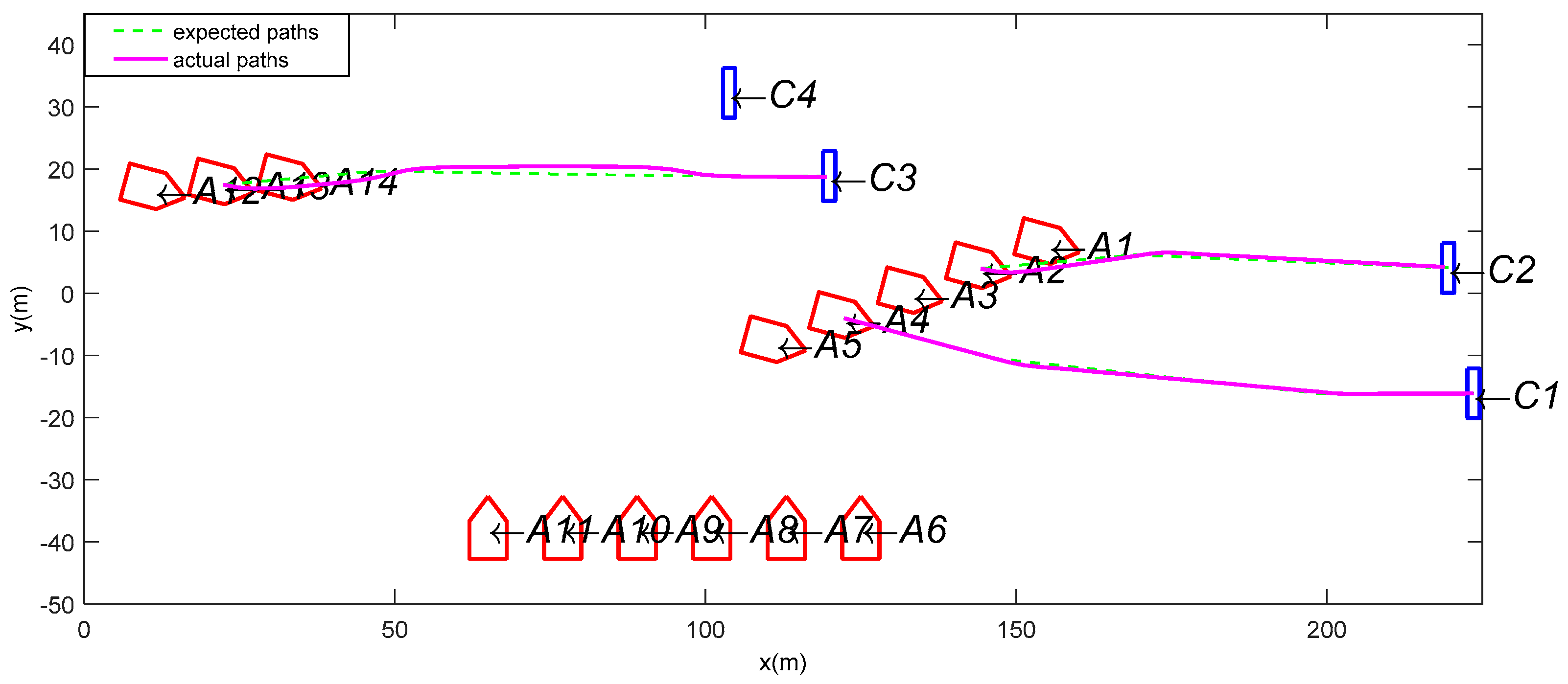
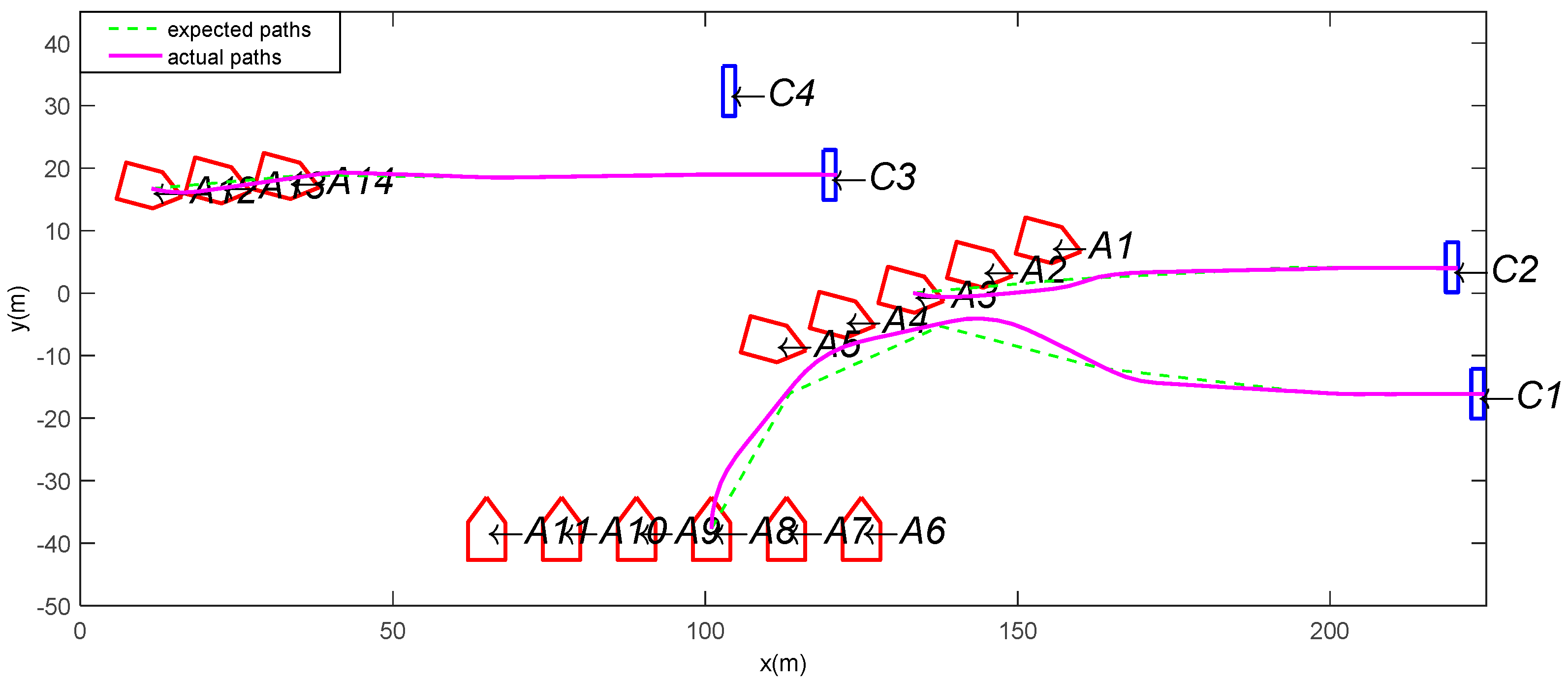
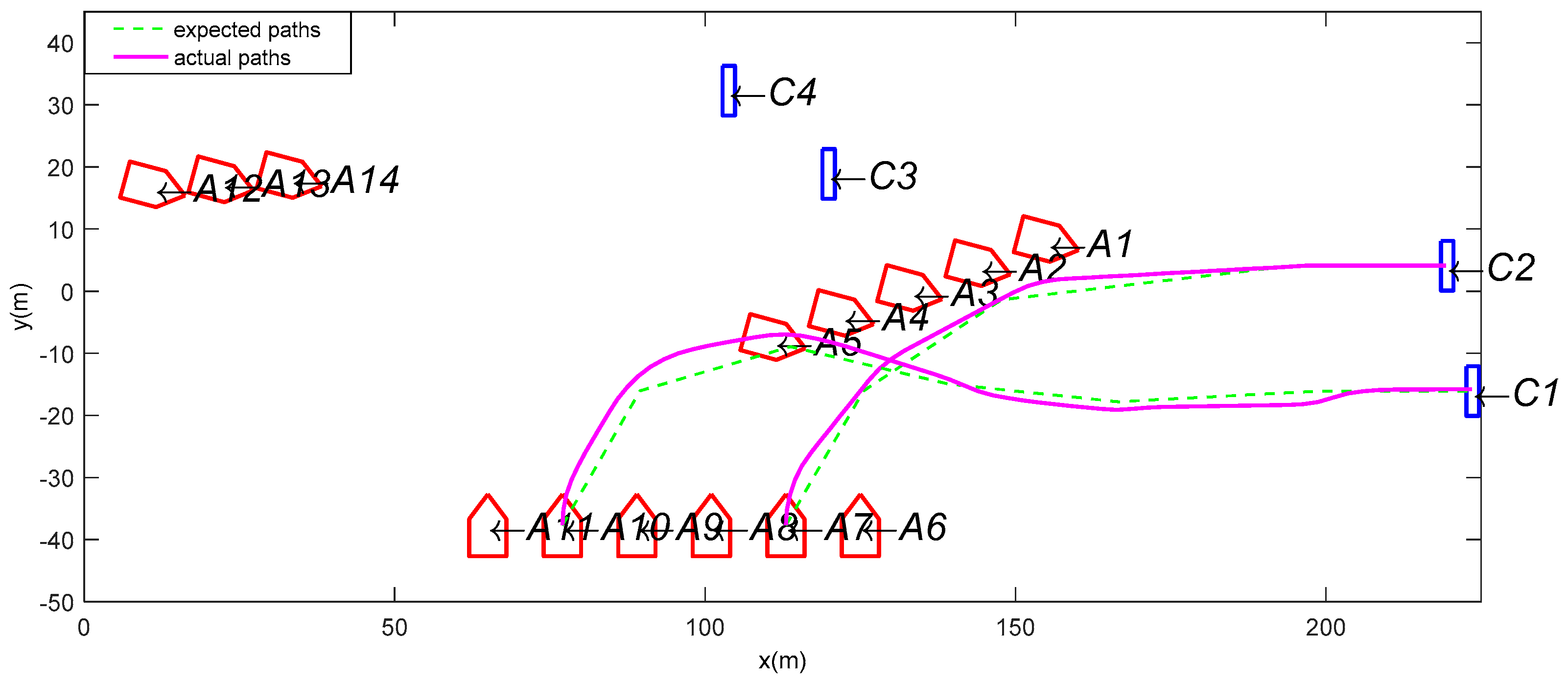
According to the launch plan, the proposed path planning method is used, and the controlled variable is discretized as within its range. After setting the initial value of as , the maximum tracking error as dmax = 2ft and the maximum tacking error of yaw angle as , the taxi paths are planned according to the flow of rolling optimization algorithm with the terminal condition that the aircraft reaches the closest location to the destination. The results of the expected paths and the actual paths are shown in Figure 9, Figure 10, Figure 11, Figure 12, Figure 13 and Figure 14.
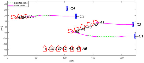
Figure 9.
The taxi paths of A1, A5 and A14.

Figure 10.
The taxi paths of A2, A4 and A13.
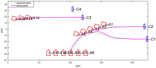
Figure 11.
The taxi paths of A3, A8 and A12.
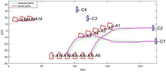
Figure 12.
The taxi paths of A6 and A9.

Figure 13.
The taxi paths of A7 and A10.
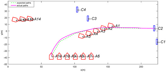
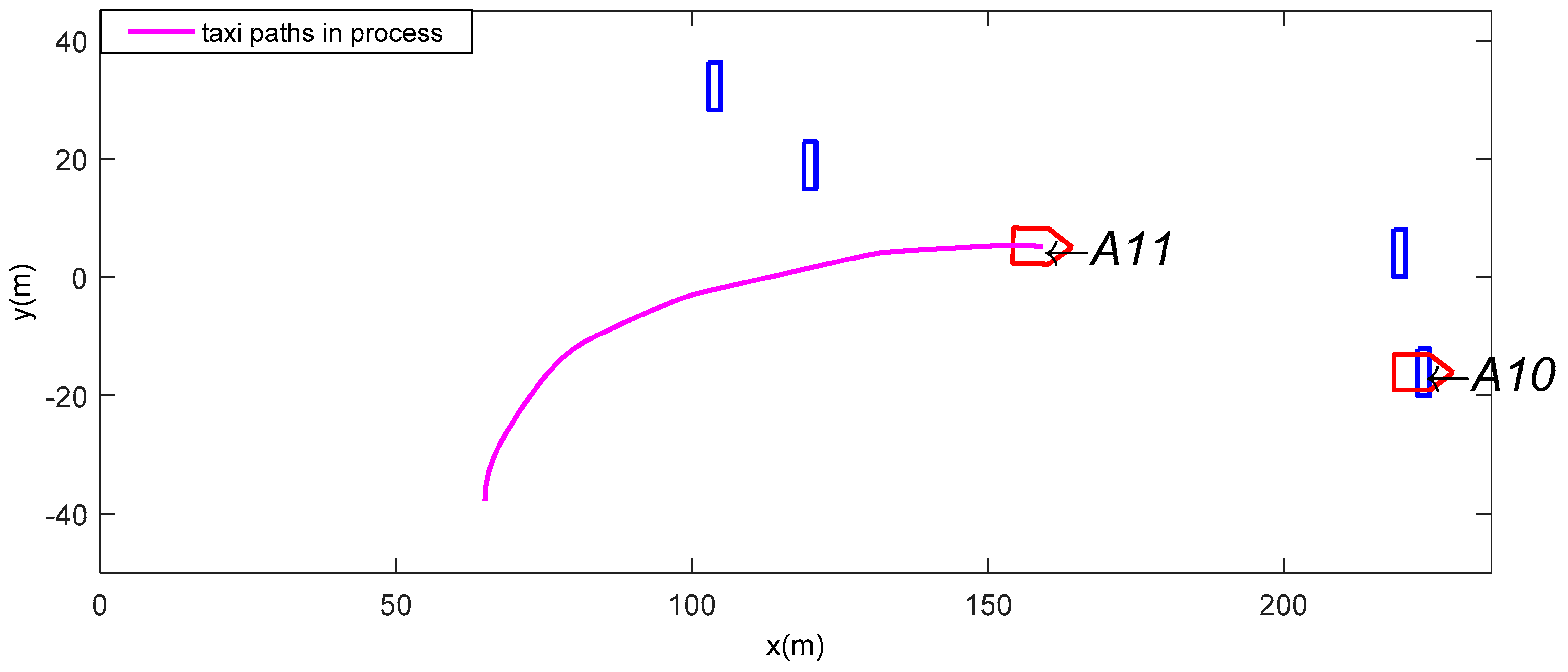
Figure 14.
The taxi path of A11.
In the above figures, the aircraft fleet can reach the corresponding catapult with reasonable taxi paths. When there is a relative large angle between two expected path segments, a greater error occurs between the expected path and the actual path. This is because as the value of can be changed only in a limited range when there is a sharp turn in the expected path, the aircraft cannot turn sharply due to the constraint of . When the expected path segment is smooth, the error becomes smaller. The final deviation of path tracking is shown in Table 3. In Table 3, each aircraft reaches the corresponding catapult with small final deviations, and the mean final deviation of path tracking is , which satisfies the requirements.
Table 3.
The final deviation of path tracking for each aircraft (1ft = 0.3048m).
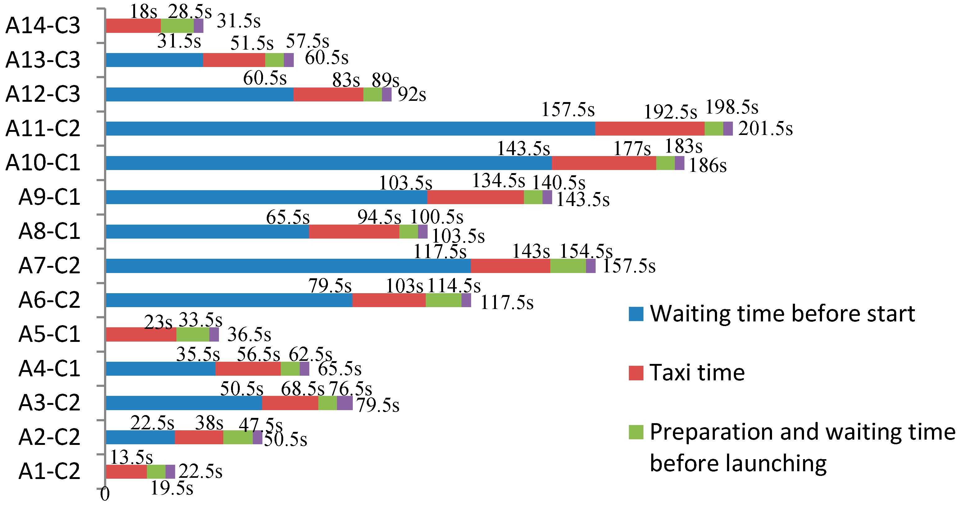
Next, each stage before an aircraft finishes launching will be concerned. Assume the starting moment of the first batch of aircraft as the initial time, the time histories of aircraft are shown in Figure 15.
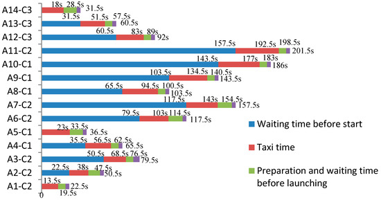
Figure 15.
The time histories of each aircraft.
Note that for the two aircraft launching on the same catapult successively, the latter will start to taxi immediately when the former one has finished its launching task. For most aircraft, they can launch immediately after the preparation on the catapult is finished. However, owing to the influence of the vortex flow, A2, A3, A5, A6, A7, and A14 still wait for the disappearance of its influence before launching, in order to ensure the safety. It takes 201.5 s for the whole fleet to safely complete the launching mission. For a single aircraft, the waiting time before start and the taxi time take the most time of the four stages, and the optimization of taxi path for each aircraft is not only beneficial for a single aircraft, but also contributes to enhancing the whole fleet’s launching efficiency and safety.
In order to explain the fact that there is no collision during the taxi process, the states of aircraft on the flight deck at some specific moments are given, as shown from Figure 16, Figure 17, Figure 18 and Figure 19.
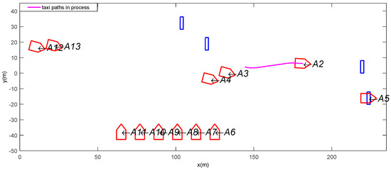
Figure 16.
The state of aircraft when t = 30 s.
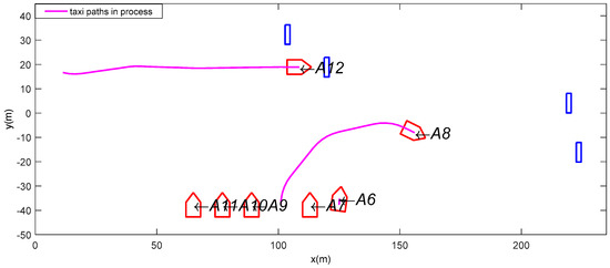
Figure 17.
The state of aircraft when t = 80 s.

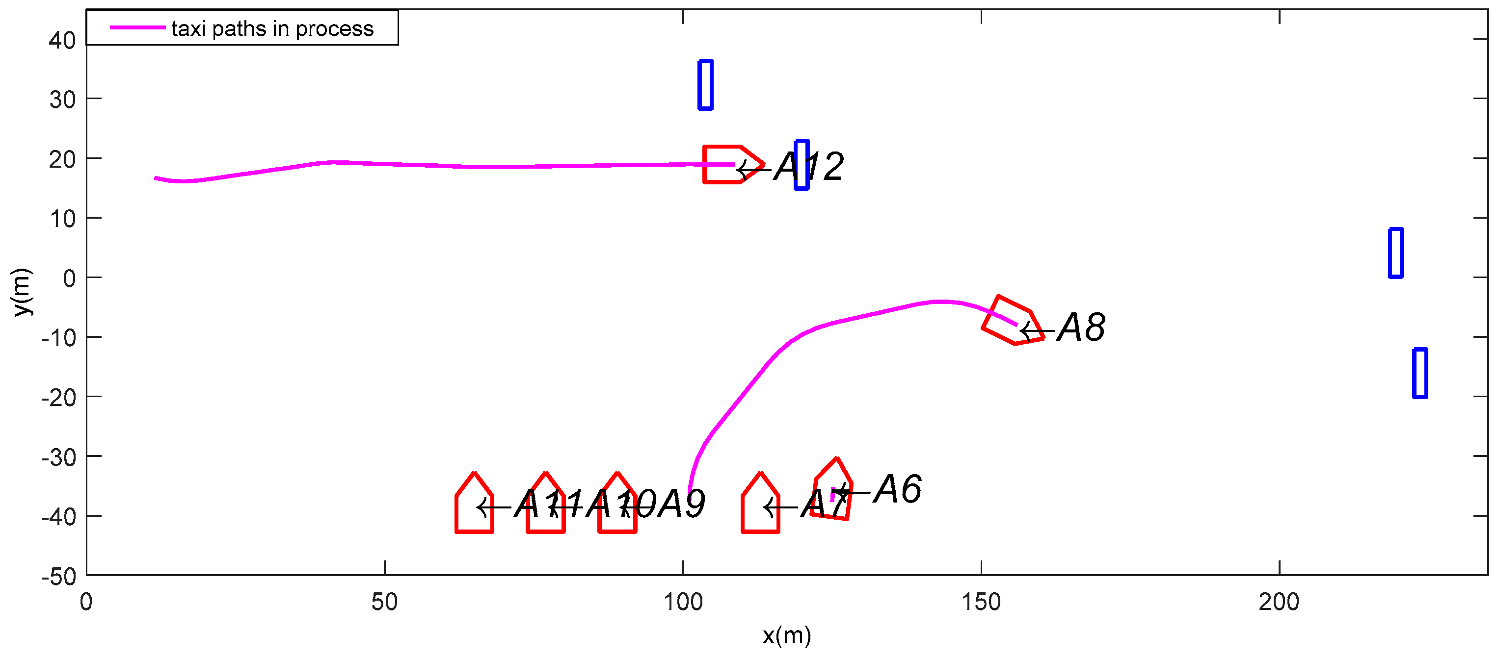
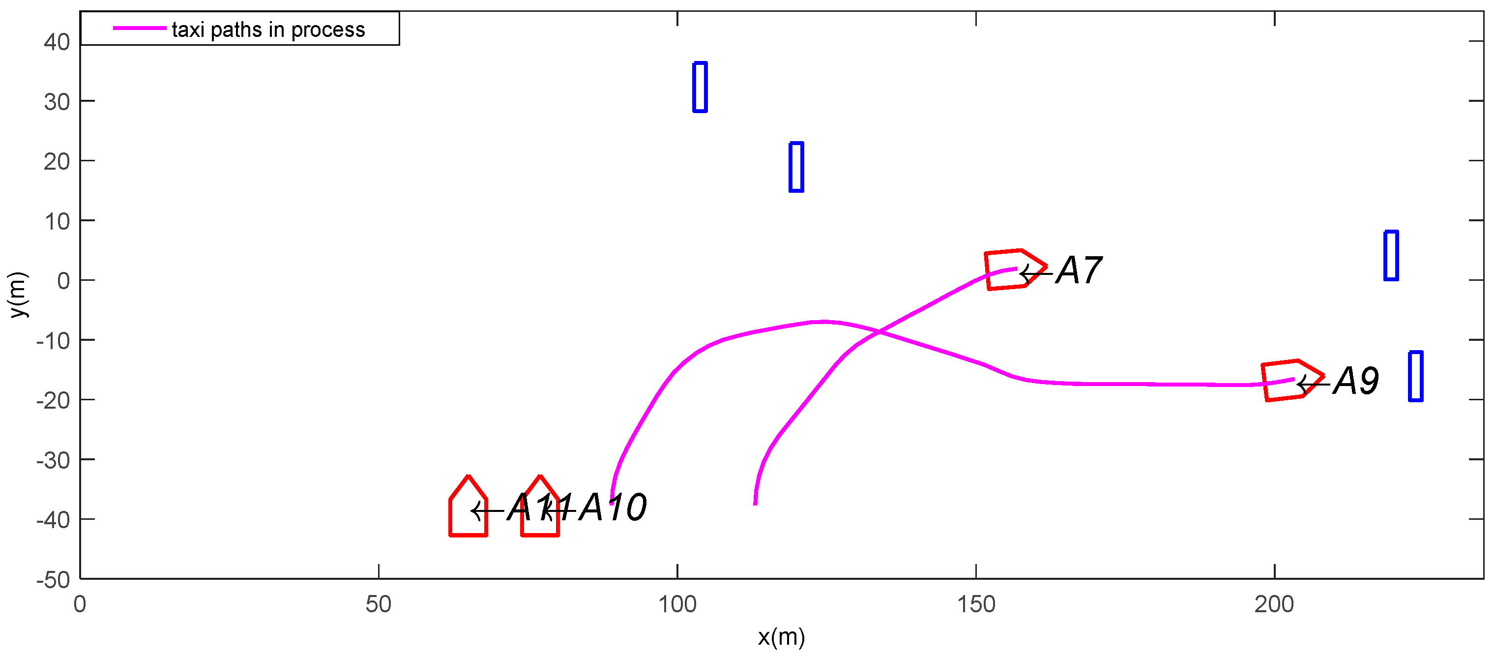
Figure 18.
The state of aircraft when t = 130 s.
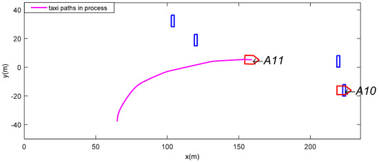
Figure 19.
The state of aircraft when t = 180 s.
As time goes by, more and more aircraft finish their launching tasks, and there are fewer aircraft left on the flight deck. When t = 30 s, A1 and A14 have left the flight deck, A5 is preparing to launch at C1, A2 is taxiing towards to C2 while other aircraft have not yet started. When t = 130 s, although the paths of A7 and A9 cross, actually they do not collide because they pass the same location at different moments. At around t = 180 s, only A10 and A11 are left on the flight deck, where A10 is already prepared to launch while A11 is still taxiing towards its catapult. The above results are consistent with the time histories shown in Figure 15, and the rationality of the results has again been verified.
5. Conclusions
In this paper, the path planning problem for aircraft fleet launching on the flight deck of carriers is studied. In the existing literature, the problem has not been studied, and it is important to generate a taxi path for each aircraft in the fleet to improve the launching efficiency and ensure safety. The problem has been formulated into an optimization problem, and the corresponding mathematical model has been established. Firstly, the ground motion and ground performance of aircraft are taken into account. Then, the work mode of the catapult and the launching time interval are described to reveal the characteristics of aircraft fleet launching from flight deck of carrier. Furthermore, to avoid collisions between two aircraft, the collision detection model has been developed. The goal of the launching mission is to minimize the total time consumption.
When planning the taxi path for each aircraft, path planning is combined with path tracking to obtain a feasible taxi path. An A*-based path planning algorithm with a dynamic cost function is proposed to adapt to changing situations. A real-time collision detection strategy is used to ensure the safety of aircraft at every moment. When generating the taxi path for a period of time in the future, the rolling optimization method is used to optimize the formulated performance index of path tracking, and the planning domain and the control domain are defined to execute the optimal control instructions only over a short period of time. In the experiment, a launching mission of 14 aircraft is considered; the results demonstrate that all aircraft can reach the appointed catapult with only small position errors, and that the proposed path tracking method is able to track the generated straight line path segments. The time history of aircraft fleet launching is given to further present the state of the aircraft during the launching task. The situations of flight decks at given specific moments are also provided to mutually verify the rationality of the established model and the validity of the path planning method.
Author Contributions
Conceptualization, Y.W. and X.S.; methodology, Y.L. and Y.W.; software, Y.L. and X.S.; validation, Y.L., Y.W. and J.S.; formal analysis, X.S.; investigation, Y.W.; resources, X.S.; data curation, J.S.; writing—original draft preparation, Y.L.; writing—review and editing, Y.W.; visualization, X.S.; supervision, Y.W.; project administration, Y.W.; funding acquisition, Y.W.
Funding
This research work is financially supported by the Fundamental Research Funds for the Central Universities with the project reference number of 106112016 CDJRC000107.
Conflicts of Interest
The authors declare no conflicts of interest.
References
- Shapley, D. Aircraft carriers: Pentagon split on issue that will shape navy’s future. Science 1975, 190, 130–134. [Google Scholar] [CrossRef]
- Ryan, J.C.; Banerjee, A.G.; Cummings, M.L.; Roy, N. Comparing the performance of expert user heuristics and an integer linear program in aircraft carrier deck operations. IEEE Trans. Cybern. 2014, 44, 761–773. [Google Scholar] [CrossRef]
- Rochlin, G.I.; La Porte, T.R.; Roberts, K.H. The self-designing high-reliability organization: Aircraft carrier flight operations at sea. Naval War Coll. Rev. 1987, 40, 76–90. [Google Scholar]
- Yu, L.C.; Zhu, J.; Shi, W.; Zhang, W. An Extended Flexible Job Shop Scheduling Model for Flight Deck Scheduling with Priority, Parallel Operations, and Sequence Flexibility. Sci. Program. 2017, 2017, 2463252. [Google Scholar] [CrossRef]
- Ryan, J.C.; Cummings, M.L. A systems analysis of the introduction of unmanned aircraft into aircraft carrier operations. IEEE Trans. Hum. Mach. Syst. 2016, 46, 209–220. [Google Scholar] [CrossRef]
- Stanton, N.A.; Harris, D.; Starr, A. The future flight deck: Modelling dual, single and distributed crewing options. Appl. Ergon. 2016, 53, 331–342. [Google Scholar] [CrossRef] [PubMed]
- Milton, R.M. Using Agent-Based Modeling to Examine the Logistical Chain of the Seabase. Master’s Thesis, Naval Postgraduate School, Monterey, CA, USA, December 2004. [Google Scholar]
- Xie, J.; Fu, B.; Bao, J. Analysis of the sortie generation capacity of embarked airwings by using the state transition diagram. Chin. J. Ship Res. 2014, 9, 1–5. [Google Scholar]
- Yue, K.; Sun, C.; Luo, M.; Su, M.; Zhao, H. Operation model on the carrier warship recovering carrier aircraft. Syst. Eng. Electron. 2013, 35, 2527–2532. [Google Scholar]
- Si, W.; Han, W.; Song, Y.; Shi, W. Takeoff scheduling of carrier plane based on multi-colonies cooperation and CLS intelligence algorithm. Appl. Res. Comput. 2013, 30, 454–457. [Google Scholar]
- Si, W.; Han, W.; Shi, W. Research on deck-disposed scheduling method of carrier planes based on PSO algorithm. Acta Aeronaut. Astronaut. Sin. 2012, 33, 2048–2056. [Google Scholar]
- Ryan, J.C.; Cummings, M.L. Development of an agent-based model for aircraft carrier flight deck operation. Model. Simul. J. 2014, 9, 5–15. [Google Scholar]
- Han, W.; Si, W.; Ding, D.; Song, Y. Multi-routes dynamic planning on deck of carrier plane based on clustering PSO. J. Beijing Univ. Aeronaut. Astronaut. 2013, 39, 610–614. [Google Scholar]
- Wu, Y.; Qu, X. Obstacle avoidance and path planning for carrier aircraft launching. Chin. J. Aeronaut. 2015, 28, 695–703. [Google Scholar] [CrossRef]
- Wu, Y.; Qu, X. A general trajectory optimization method for aircraft taxiing on flight deck of carrier. J. Aerosp. Eng. 2018. [Google Scholar] [CrossRef]
- Cui, J.; Wu, Y.; Su, X.; Song, J. A task allocation model for a team of aircraft launching on the carrier. Math. Probl. Eng. 2018, 4210, 1–12. [Google Scholar] [CrossRef]
- Sebok, A.; Wickens, C.; Sarter, N.; Quesada, S.; Socash, C.; Anthony, B. The automation design advisor tool (ADAT): Development and validation of a model-based tool to support flight deck automation design for nextgen operations. Hum. Factors Ergon. Manuf. Serv. Ind. 2012, 22, 378–394. [Google Scholar] [CrossRef]
- Gerz, T.; Holzäpfel, F.; Darracq, D. Commercial aircraft wake vortices. Prog. Aerosp. Sci. 2002, 38, 181–208. [Google Scholar] [CrossRef]
- Abene, A.; Dubois, V. Fundamental aspects of the vortex flow on cones. Aerosp. Sci. Technol. 2012, 22, 1–8. [Google Scholar] [CrossRef]
- Jung, D.; Tsiotras, P. On-Line Path Generation for Unmanned Aerial Vehicles Using B-Spline Path Templates. J. Guidance Control Dyn. 2013, 36, 1642–1653. [Google Scholar] [CrossRef]
- Dai, R.; Cochran, J. Path planning and state estimation for unmanned aerial vehicles in hostile environments. J. Guidance Control Dyn. 2010, 33, 595–601. [Google Scholar] [CrossRef]
- Faisal, M.; Mathkour, H.; Alsulaiman, M. AntStar: Enhancing optimization problems by integrating an Ant System and A* algorithm. Sci. Programm. 2016, 2016, 5136327. [Google Scholar] [CrossRef]
- Wu, Y.; Qu, X. Path planning for taxi of carrier aircraft launching. Sci. China Technol. Sci. 2013, 56, 1561–1570. [Google Scholar] [CrossRef]
- Shen, C.; Shi, Y.; Buckham, B. Integrated path planning and tracking control of an AUV: A unified receding horizon optimization approach. IEEE/ASME Trans. Mechatron. 2017, 22, 1163–1173. [Google Scholar] [CrossRef]


© 2018 by the authors. Licensee MDPI, Basel, Switzerland. This article is an open access article distributed under the terms and conditions of the Creative Commons Attribution (CC BY) license (http://creativecommons.org/licenses/by/4.0/).