Article

A Parametric Tool for Studying a New Tracheobronchial Silicone Stent Prototype: Toward a Customized 3D Printable Prosthesis

by
Jesús Zurita-Gabasa
1,
Carmen Sánchez-Matás
2,
Cristina Díaz-Jiménez
3,
José Luis López-Villalobos
2 and
Mauro Malvè
1,4,*
1
Department of Engineering, Public University of Navarra (UPNA), Campus Arrosadía s/n, E-31006 Pamplona, Spain
2
Department of Thoracic Surgery, University Hospital Virgen del Rocío, Avenida Manuel Siurot s/n, E-41013 Sevilla, Spain
3
AIN-Asociación de la Industria Navarra, Ctra. Pamplona, 1. Edif. AIN, E-31191 Cordovilla, Spain
4
CIBER-BBN, Research Networking in Bioengineering, Biomaterials & Nanomedicine, C/Mariano Esquillor s/n, E-50018 Zaragoza, Spain
*
Author to whom correspondence should be addressed.
Mathematics 2021, 9(17), 2118; https://doi.org/10.3390/math9172118
Submission received: 22 July 2021 / Revised: 20 August 2021 / Accepted: 24 August 2021 / Published: 1 September 2021
(This article belongs to the Special Issue Numerical Simulation in Biomechanics and Biomedical Engineering)

Abstract

:
The management of complex airway disorders is challenging, as the airway stent placement usually results in several complications. Tissue reaction to the foreign body, poor mechanical properties and inadequate fit of the stent in the airway are some of the reported problems. For this reason, the design of customized biomedical devices to improve the accuracy of the clinical results has recently gained interest. The aim of the present study is to introduce a parametric tool for the design of a new tracheo-bronchial stent that could be capable of improving some of the performances of the commercial devices. The proposed methodology is based on the computer aided design software and on the finite element modeling. The computational results are validated by a parallel experimental work that includes the production of selected stent configurations using the 3D printing technology and their compressive test.

1. Introduction

Tracheobronchial or airway stents are tubular scaffolds used for enlarging a constricted airway or supporting the trachea and/or bronchi from collapse. This can be due to airways obstructions caused by prolonged intubation, or benignant or malignant carcinoma and tracheomalacia that may lead to several morbidities. Normally, tracheobronchial prosthesis is necessary as a last chance if the stenosis cannot be treated with surgical means [1]. Airway stents are available in different materials and shapes and can be classified into four categories: silicone, balloon-expandable metal, uncovered and covered self-expanding metal [2]. Solid silicone tubes have been designed for avoiding in-stent restenosis, but are affected by migration and obstruction as main side effects [3]. Metallic devices, usually made of steel or nitinol, are similar to those used in the cardiovascular field. They promote re-epithalization that avoids migration, but cannot avoid restenosis, becoming less efficient as soon as the airway tissue grows and cause frequent granulations [4]. Partially, the covered metallic stents or hybrid stents have solved the problem of the restenosis [5]. However, covered self-expanding metal devices are associated to necrosis of mucosa and fistula formation due to the radial force applied by the stent [6].
The choice of a specific stent is determined by the type of lesion [7]. Silicone prostheses are usually used for both benign and malign pathologies. Metallic devices are indicated for malignant obstructions, but their use has been recently not recommended if not fully covered [8]. Silicone prostheses are commonly used in Europe and Japan [9,10] while metallic or hybrid stents are more frequently implanted in U.S.A. so that the use of these scaffolds are also driven by the clinicians school. In this sense, each stent has advantage and contraindications, but the response of the tissue to their implantation is always problematic due to unavoidable inflammations and reaction to the foreign body. Additionally, all stent categories are, in general, very rigid and tend to impede the physiological maneuvers of coughing, swallowing and forced breathing [2,11,12,13]. For these reasons, the design of new prostheses capable of addressing the flaws of the existing stents is necessary. Several absorbable polymeric stents have been experimentally tested for their possible use in the airways. The associated inflammatory reaction has been less extensive with respect to permanent stents [14]. Unfortunately, the degradation time of these type of stents in the trachea or bronchi remains difficult to control, or is even undefined [15]. In the last three decades, the clinical experience has demonstrated that there is a large number of situations in which commercial stents could not solve the clinical problem [16].
A tracheobronchial prosthesis should satisfy different requirements. It should be easy to be inserted and eventually removed. It should ideally avoid migration and be biocompatible, limiting the tissue reaction [10]. It should adapt to the airway and possibly be patient customizable [17]. Airway stent implantation could in fact result in inefficient clinical results due to the poor fit of the stent in the airway [18]. Personalized prosthesis can already be ordered to commercial factories. The personalization regards size, diameters and angles measured by computerized tomography (CT) scan and bronchoscopy. Nevertheless, the baseline design remains unchanged despite the personalization, as the stents are still straight tubes [16]. In this context, clearly, a customization that only provides changes of main geometrical characteristics is too simple and not efficient. The three dimensional (3D) printing offers a new opportunity that is rapidly entering in the clinics and allows rapid prototyping and fabrication of patient-specific anatomical shapes [10]. This technique has been rapidly entered in the clinics and it has been used recently for surgical treatment [19]. In the literature, it is stated that it is already capable of manufacturing optimized devices made of silicone or elastic thermoplastics for a particular patient. Stents can be designed for matching a particular patient specific anatomy and for exerting the necessary radial force [16]. The FDA has recently released guidelines on the 3D printing of medical devices [20].
The 3D-dimensional printing technique has already been reported in many clinical applications, including the thoracic surgery [21,22]. The possibility to convert anatomic images into 3D objects using this technique helps the surgeon to overcome specific problems and prepare the surgery [23]. Miyazaki et al. [24] used a 3D printed airway model to manage a post-transplant airway complications of bronchial anastomosis. Guilbert et al. [10] utilized a 3D printed models of corrected airways to select and customize airway stents. Although promising results have been obtained, other clinical complications such as mucus plugging and migration have been not solved. In the same line, Gildea et al. [18] treated complex stenoses due to granulomatosis with polyangiitis in two patients while Cheng et al. [25] treated a patient with a tracheal dehiscence. Morrison et al. [26] successfully applied the 3D printing technology to produce a personalized medical device for treating the tracheobronchomalacia. Debiane et al. [27] use the stereology to quantify the granulation. They have analyzed which type of tissue contributes more to the pathology and used this information for designing a customized drug eluting tracheo-bronchial stent.
Furthermore, a few studies have presented engineering tools for the design of new tracheobronchial parametric and/or customizable stents. Melgoza et al. [28,29] presented an integrated tool for the design of an innovative customized tracheal stent with aim of meeting the most critical requirements of a prosthesis. For this, the experience collected by clinicians and patients during the interviews and hospital visits has been used. Vearick and coworkers proposed a modification of the commercial Dumon stent [30] and introduced a fiber reinforced silicone prosthesis [31]. Schopf et al. [14] introduced a new polymer absorbable stent with a spiral shape evaluating the clinical signs and histological reaction in an experimental rabbit model.
Taking into account these aspects, in the present study we focus on the silicone Dumon stent. We aimed to design, simulate, produce and test a new tracheobronchial prosthesis that is customized to the patient, printable with 3D technology and overtakes some of the limitations of the commercially available devices. In particular, we proposed a parametric tool capable of simulating the influence of several variations in the geometry of the prosthesis, yet assessing the importance of each single parameter. Additionally, the tool was validated against an experimental test aimed to prove the reliability of the computational results.

2. Materials and Methods

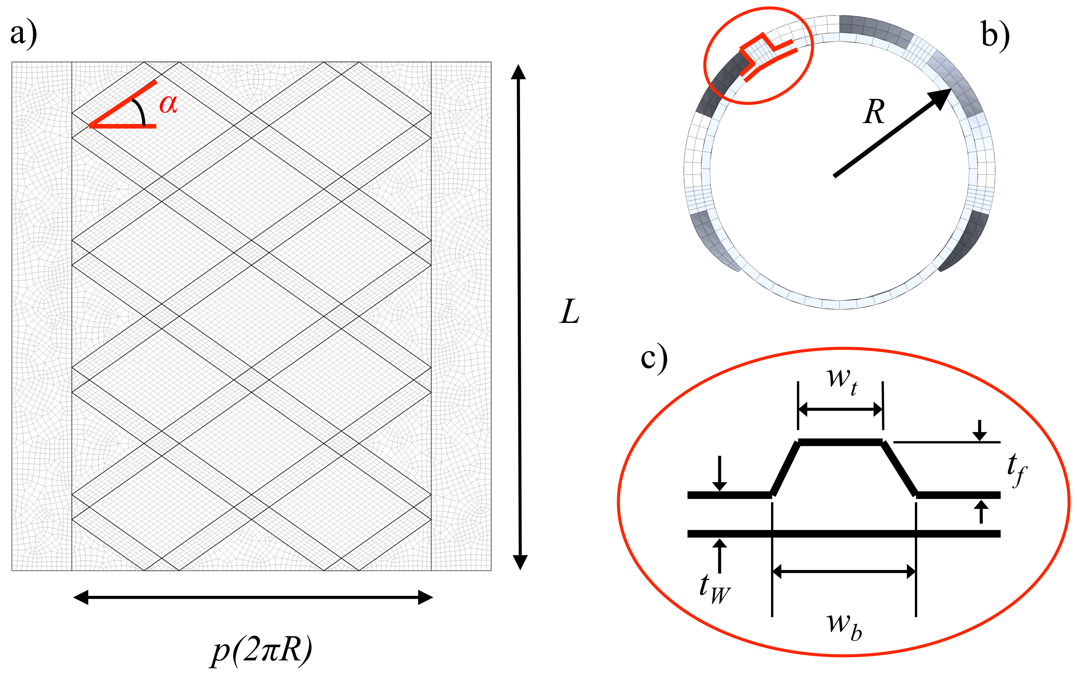
2.1. Parametric Geometry of the Tracheobronchial Prosthesis

The new stent was designed to be tubular. The baseline CAD model, created with the in-house code, is represented in Figure 1. The outside of the tube was designed with an upward reinforcing structure that is similar to the typical X-pattern metallic stents (see Figure 2). The device geometry has been parametrized in order to study the effect of each single feature on the mechanical properties. Through modulating the different parameters in fact, the flexibility, the radial stiffness and the mechanical strength of the stent can be manipulated. In Figure 2, the parameters considered in this work are depicted on the unwrapped stent (Figure 2a), on the frontal view of the stent (Figure 2b) and on a detail representing the fibered stent wall Figure 2c). The baseline tube resembles the widely known Dumon prosthesis [32]. The outer skewed fibers that reinforce the baseline tube are located only in a percentage of the total outer surface area and they progressively reduce their thickness (see Figure 2). Differently from the commercial Dumon prosthesis, but similarly to the natural stent [33], the new prototype presents a novel design in which the radial stiffness varies. The reason is the particular behavior of the trachea during the physiological maneuvers of forced breathing, coughing and swallowing. The trachea is composed by a transversal muscular membrane and stiffer cartilage rings. During breathing and coughing, for example, the trachea dilates and collapses, enlarging and reducing its diameter. Especially during coughing, it is the muscular membrane that considerably deforms. It has been reported that the Dumon stent is rigid, as it has a constant thickness. For this reason, the side of the prosthesis that corresponds to the transversal membrane has been designed without fibers. Hence, as visible in Figure 1 and Figure 2 the fibers cover only a portion of the outer prosthesis surface that could be also varied as it is the parameter p as explained below.
The shape of the cells that reinforces the outer prototype surface is governed by their number in longitudinal ( n L ) and radial ( n R ) direction. An increase of the cells number in longitudinal direction promotes smaller pitch angle α ( also called braiding angle in metallic stents, see Figure 2) while an increase of the cells number in circumferential direction promotes higher pitch angle α . As visible in Figure 2, with smaller pitch angles, the cell shape is a rhombus circumferentially oriented around the outer prosthesis surface. With higher pitch angles, the cell shape is a rhombus longitudinally oriented. As visible in Equation (1), the pitch angle α can be computed as a function of the number of circumferential and longitudinal cells given to the prosthesis:
α = a t a n L / n L p ( 2 π R ) / n R
where L is the length of the prosthesis, n L is the number of cells in longitudinal direction, p is the percentage of the external prosthesis surface that is fiber reinforced, r is the inner radius of the prosthesis and n R is the number of cells in radial direction. The parameter p governs the extension of the fibers around the external surface of the tube and, as a consequence, the width of the region of the prosthesis without fibers.
The dimensions of the fibers are parametrized. In particular, fiber bottom and top width are represented with w b and w t in Figure 2c). Finally, the thickness of the stent is represented by t w and that of the fibers by t f . Of course, stent radius R and length L are also parameters and they can be adapted to a specific patient. In this way, the device is customizable.
In Figure 2b), it is visible that the fiber thickness gradually decreases (see also Figure 1. This thickness has a biomechanical relevance, as it is known that a roundoff of the edges of the whole geometry of the prosthesis reduces tissue damages. For these reasons, the thickness was gradually reduced (from 2 to 0.8 mm in Figure 2b) for the prosthesis fabrication and for computational models of the experimental validation. On the contrary, as the mechanical response of the prosthesis is not affected by this parameter, the overall numerical simulations of the computational study were generated with a constant thickness.
In Table 1, the parameters and corresponding values are summarized. The number of the necessary computations that consider all the variations would imply a number n = 972 simulations. In this work, only n = 86 simulations were run, considering the most important parameter variations and taking into account the computational costs. In fact, the goal of the study is twofold: for one side, a parametric analysis of the new prototype is carried out. On the other side, the final aim of the study is to present a computational tool capable of performing all the necessary simulations for the customization of a prosthesis for a specific patient. For this reason, not all the possible parameter combinations are given or simulated.

2.2. Stent Fabrication

Three tracheobronchial stent prototypes were fabricated by ACEO - 3D PRINTING WITH SILICONES (Wacker Chemie AG, ACEO Campus, Burghausen, Germany) starting from the STL (Stereolithography) files of the prostheses. The stents were 3D-printed using medical silicone technology. They were printed using medical silicone of modulus of elasticity of 15 ± 0.4 MPa and hardness 3.5 ± 0.2 MPa that were obtained after a material property analysis at AIN (Asociación de la Industria Navarra, Pamplona, Spain). In particular, the stress–strain curve was obtained by means of a traction test. The obtained curve evidenced a linear elastic region for deformation until about 37%. The three samples were built adding single layers composed by thin longitudinal slices using a manufacturing process. In Figure 3, the three prosthesis are shown after the printing process. The stents’ height and outer diameter were 50 mm and 18 mm, respectively. The stent wall and fiber thickness was 1 mm each and the fibered reinforced surface covered the 75 % of the device perimeter. The pitch angle α was changed within the three prototypes. Its values, summarized in Table 2, produce different cell configurations longitudinally and transversally. The number of cells in the two direction changes: prototype # 1 , later called A 3 , has 3 × 5 cells, prototype # 2 or A 4 has 4 × 5 cells, and prototype # 3 or A 5 has 5 × 3 cells. As can be seen in the Figure 2, the difference between the three fibered stents is represented by the pitch angle that promotes different cell shapes as explained in the previous section.

2.3. Prosthesis Experimental Testing

As the prototypes are tubular, it was not possible to perform a traditional radial compressive test for assessing their radial stiffness as in the case of bare metallic stent for cardiovascular applications. With the aim of assessing the resistance of the prosthesis to compressive loads and to determine the effect of the fibers on the mechanical response of the prosthesis, a flat plate test have been carried out in NAITEC (Navarre Technology Center of Automotive and Mechatronics, Pamplona, Spain). The printed prototypes were placed between two flat plates (Figure 4a), compressed under displacements control until the inner prosthesis diameter was reduced to zero (Figure 4b) and unloaded with a compression rate of 0.1 m m / s . The force was measured by means of an Advanced Digital Force Gauge (AFG250N) LE01/50 (Mecmesin, Slinfold, West Sussex, UK).

2.4. Prosthesis Computational Modelling

The geometry was parametrized using an in-house software that automatically generates the computational grid. The aim of the parametrization is the analysis of the effect of each geometrical feature and of the customization of the stent to different patients. For facilitating the automatization of the simulations, the geometries and grids were generated contemporaneously. The generation of the mesh has been carried out using prismatic elements selecting the desired element size directly on a specific geometrical configuration hence fixing first the desired values of each parameter described in the previous section. In details, the in-house code was developed in C language and consists in five steps.
In the first step, the basic planar geometry has been generated. The corresponding parameters are the prosthesis length L, radius R, number of longitudinal fibers n L and fiber thickness t f . According to Figure 5a six areas are firstly defined: rectangular surfaces corresponding to the fibers (a), rhomboidal or quadratic surfaces corresponding to the cell unit (b), triangular surfaces corresponding to regions between the unit cells and the non-fibered region (c), triangular surfaces between fibers (d) or unit cells (e) and boundary of the fibered region of the prosthesis sections and rectangular non-fibered surfaces (f).
In the second step, the surfaces a, b, c are meshed with structured quadrilateral elements as sketched in Figure 5b. In contrast, surfaces d, e and f are meshed with unstructured quadrilateral elements. The quadrilateral mesh is obtained starting from a previous triangularization of the surfaces performed by means of a Delaunay algorithm. The grid obtained after step 2 is represented in Figure 5b.
In step 3, the planar mesh of the surfaces a, b and c is extruded in normal direction obtaining the tridimensional brick mesh sketched in Figure 5c. Here, the considered parameters are the fiber thickness t f and the top and bottom width w t and w b , respectively, (see Figure 2c).
Then, in step 4, the rest of the surfaces mesh are extruded in normal direction, obtaining the grid sketched in Figure 5d.
In the last step, the mesh is bent, obtaining a cylindrical solid meshed with hexahedral elements obtaining the tubular prosthesis depicted in Figure 2e.
In the Figure 6, the mesh topology is shown for the unwrapped geometries used for the experimental validation. The total number of elements used for the computations varies depending on the particular configuration to be studied. In particular, it ranges from 8198 to 61,480 prismatic elements, while the number of nodes ranges correspondently between 14,218 to 81,387. The average element size of the grid is 0.7 mm. The mesh element size was selected after an appropriate mesh size sensitivity analysis. The Figure 7 shows the force-displacements curve for grids with different maximum element sizes from 1 mm to 2 mm (that correspond to average element sizes of 0.7 mm and 1.6 mm, respectively). For this analysis, we used a prosthesis with n R = 5 , n L = 5 , t w = 0.5 mm, t f = 2 mm, w b = 2 and w t = 2 . A comparison of the presented force-displacement curves proves the independency of the results on the discretization. The finest mesh refinement (black line with circles) converged adequately within 2 % of the densest evaluated mesh (yellow line with circles).
The computational analysis was performed using ANSYS Mechanical APDL Release 18 (ANSYS Inc., Canonsburg, PA, USA). In this commercial software, the simulation of compression test of biodegradable stents was performed by a static structural analysis with the aim of determining the load-displacements diagram and eventual additional variables such as the principal stresses and strains. The grids generated with the in-house code described above were imported in Ansys where the set-up of the models and the corresponding boundary conditions were applied. Steady loading was assumed. The order of element shape function was selected as linear and of the first order. The material properties of the medical silicone estimated during the experimental test were specified in Ansys for defining the material. In particular, the modulus of elasticity and the Poisson coefficient used for the simulations are 15.2 MPa and 0.29, respectively. The linear elastic behavior of the material used in the presented simulations is reasonable as the strains are achieved up to 0.2. This value is overtaken only in high compressive states and specific flexible models. Furthermore, as mentioned before, the linear elastic behavior can be correctly assumed until a strain value of about 0.37.
Based on the experimental compression test, the lower plate was fixed, and the upper plate was moved until the desired radial displacements are reached (14 mm). The contact between the plates and the prosthesis has been carried out frictionlessly. Large displacements have been switched on in the Ansys solver. The loads and displacements were registered and plotted as shown in the next section. It has to be noted that the radial stiffness was measured only for a single orientation of the prosthesis. In particular, the prosthesis was compressed in the direction in which the trachea usually experiments with the larger displacements [11].

3. Results

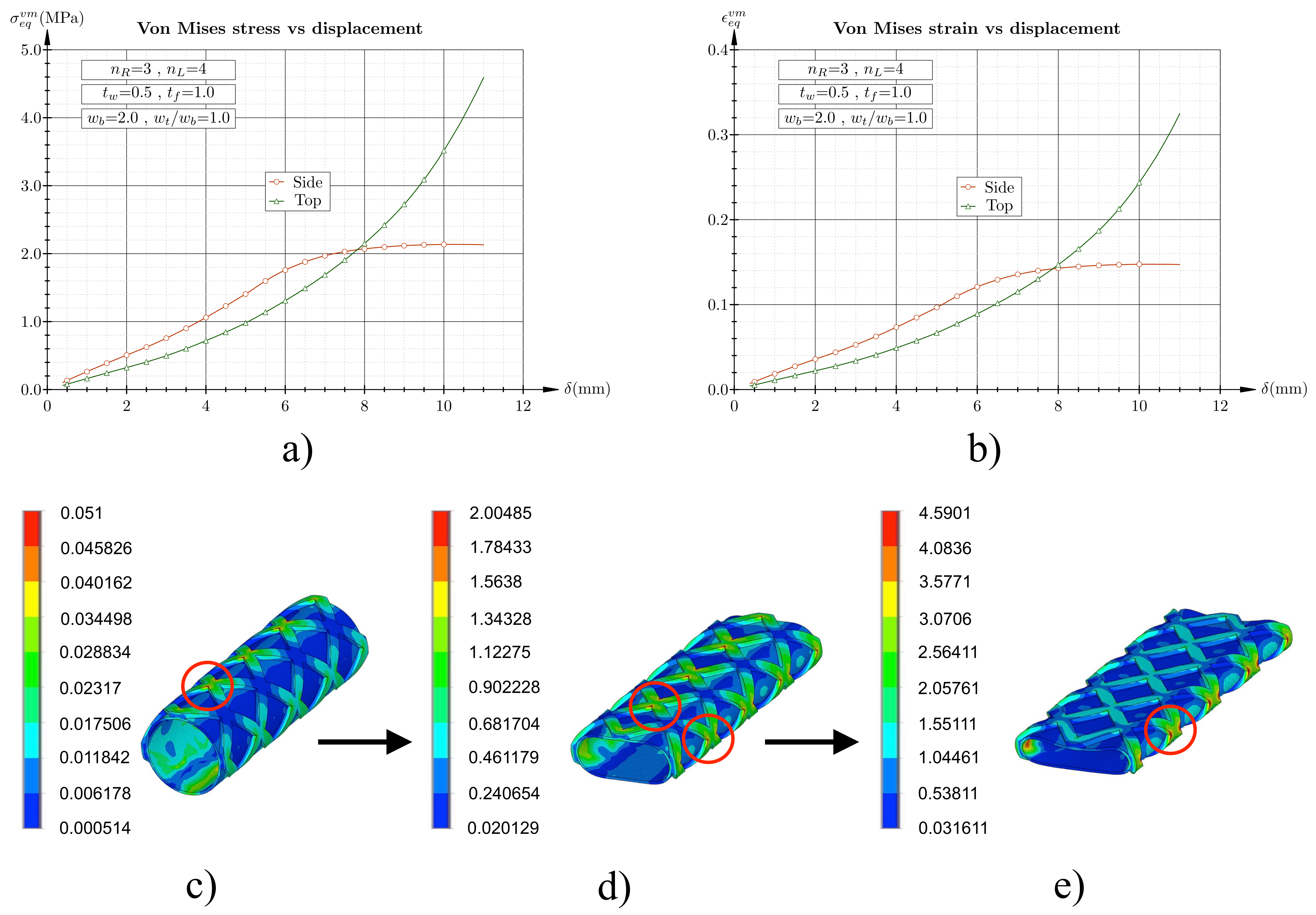
3.1. Flat Plate Test Simulation

In Figure 8, the radial force is plotted versus the radial displacement for different values of the fiber bottom width w b and fiber thickness t f . The comparison is shown for a specific configuration in which the ratio w t / w b is fixed and equal to unity and the same number of cells in radial and longitudinal direction have been considered ( n L = n R = 5 ). The plot shows an increase of radial force caused by an increase of the fiber bottom width w b and fiber thickness t f . For a fixed fiber thickness t f the increase of the radial force becomes more marked for increasing fiber bottom widths w b , being the increase of the last case ( t f = 1 , w b = 1 and 2) the highest (blue lines with circles).
In Figure 9, the influence of the number of cells located in circumferential ( n R ) and longitudinal direction ( n L ) on the radial force is analyzed. Figure 9 shows selected prosthesis configurations with a combination of n R = 3 , 4 , 5 and n L = 3 , 4 , 5 . However, the presented results can be generalized for different values of n R and n L . The comparison is shown for fixed width ratio w t / w b = 1 and fiber and wall thickness t w = t f = 0.5 mm. The comparison allows clarifying the role of the cell shape on the radial stiffness. It is clearly visible in fact that an increase of the stiffness is promoted when n R < n L , i.e., for smaller pitch angle α (see Section 2.1). On the contrary, if n R > n L , i.e., for higher pitch angle α , the radial stiffness decreases. Summarizing, fixing the fiber and wall thickness and the top and bottom fiber width, a prosthesis with α < 45 is stiffer than a prosthesis with α > 45 . For α = 45 the shape of the stent cell is squared and this configuration corresponds to a change of the trend. Maintaining α = 45 , the plot of Figure 9 highlights that if the number of cells increases, the radial stiffness also increases as demonstrated by a comparison between the black line with triangle ( n L = n R = 3 ), the red line with squares ( n L = n R = 4 ) and the green line with circles ( n L = n R = 5 ). In any case, the increase is not extremely marked, as demonstrated by other cases such as n L = n R = 3 and n L = n R = 4 .
In Figure 10, the total thickness of the prosthesis fixed and equal to 1.5 mm is distributed to the wall thickness t w and to the fiber thickness t f . Different percentages are given to these two parameters, keeping their sum constant. The figure shows the case of number of radial and longitudinal cells n R = 3 and n L = 4 , respectively. As for the previous plots, the results can be generalized for other configurations with different numbers of cells (with n R < n L ). Additionally, the bottom and top width are w b = 2 mm and w t = 1.2 mm. The figure shows that, as expected, a higher radial stiffness can be obtained if t w > t f . Notwithstanding, the radial stiffness can be increased when t w < t f , changing the fiber dimensions, increasing w b and eventually w t .
In Figure 11, the variation of the fiber shape is studied varying the bottom width w b and the bottom and top width ratio w t / w b . The figure clearly highlights that an increase of the fiber width promotes a increase of the radial stiffness for a fixed wall thickness t w and fiber thickness t f . In the figure, it is shown the specific case in which again n R = 3 and n L = 4 . Furthermore, in this case, similar curves have been obtained for different configurations (with n R < n L ).
In Figure 12, the stiffness of selected prosthesis configurations is compared. The figure illustrates that different stiffness can be obtained, modulating the different parameters in which the prosthesis has been designed. In the figure, we can see the specific configuration n R = 3 and n L = 4 as in the Figure 10 and Figure 11. The figure shows the case of prosthesis with the same total thickness t w + t f = 1.5 mm. As visible, the stiffness of the prosthesis with the wall thickness t w = 0.75 mm (black line with squares, Figure 12 is very similar to that obtainable with a reduced wall thickness t w = 0.5 mm and a higher fiber bottom width w b = 2 mm, with a constant fiber thickness w b / w f = 1 (red line with circles). Additionally, the same stiffness could be also obtained using a fiber bottom width w b = 3 mm and a ratio w b / w f = 0.5 (green line with triangles). In the same way, the prosthesis with t w = 1 mm, with a fiber bottom width of w b = 2 mm and a ratio w b / w f = 0.6 (black line with triangles, Figure 12) has a similar stiffness of a prosthesis with wall thickness t w = 0.5 mm, with a fiber bottom width of w b = 4 mm and a ratio w b / w f = 0.5 (yellow line with triangles in the Figure 12) and of a prosthesis with wall thickness t w = 0.5 mm, with a fiber bottom width of w b = 3 mm and a ratio w b / w f = 0.5 (green line with circles). In this last case, the stiffness is different among the three configurations at the beginning of the deformation (for a compressive force in the range 0–7 N). Here, a thicker tube promotes a stiffer prosthesis of course. For higher deformations (after a displacement δ > 7.5 mm), the stiffness of the three prostheses tends to be the similar.
The equivalent Von Mises stress and strain evolution during the compression test is shown in Figure 13a,b. The figure refers to specific configurations indicated in a and b. Nevertheless, this behavior is the same in all the configurations. Von Mises stresses and strains are initially located at the top of the prosthesis surface (Figure 13c) and tend to increase. Furthermore, at the prosthesis sides, the stresses and strains tends to increase, until the values at both locations meet (close to the 68 % of the total compression, Figure 13a,d. Then, the maximum stress changes location from the top to the side of the prosthesis surface (Figure 13e).

3.2. Flat Plate Experimental Testing

The comparison of the simulations results with the experimental test performed on the three 3D-printed prostheses allows the validation of the computational parametric framework. In Figure 14, the compressive force is represented as a function of the radial displacements for both in silico and experimental model for the prototype # 1 (a), # 2 (b) and # 3 (c). The results offer a very good match. In particular, an excellent match can be seen in the range of radial displacements between zero and 8 mm for all the prototypes while between 8 mm and 15 mm the curves tend to separate. Prototypes # 1 and # 2 seem to moderately overestimate the force in the displacement range 8–14 mm while prototype # 3 seems to slightly underestimate the necessary force in the same interval. The maximum difference between curves in this range is 1 mm for prototype # 1 , 0.5 mm for prototype # 2 and 0.4 mm for prototype # 3 . However, the agreement between curves for prototypes # 1 and # 2 is very good until a a radial displacement of 10 mm while the prototype # 3 shows a separation between experimental and computational curve that starts already at a radial displacement of 2 mm. From this displacement, the separation between the curves increases moderately, it stays almost constant between 8 and 10 mm then further increases, even very slightly, between 10 and 14 mm. The reason of these differences at higher displacements may be due to the different value of the friction in the experimental and computational study and to the complex deformation of the prototypes at crushing. In Figure 4b, the prototype is compressed between plates. Unfortunately, in the computational analysis, the complete buckling cannot be obtained.

4. Discussion

The goal of this study was the evaluation of the mechanical properties of a new tracheobronchial stent prototype, through the use of computational and experimental modeling. For this reasons, we have presented a parametric in-house tool capable of designing and meshing several geometrical configurations of the prosthesis. Then, the effect of each single parameter variation on the stent radial stiffness was analyzed by means of numerical simulations. In the presented tool, there are additional parameters that could be changed and even they do not contribute to the mechanical performance of the prosthesis, they are useful for creating a patient specific device. For example, the typical main variables such as the inner radius and the length of the prosthesis can be adapted to the patient necessities and a customized device can be rapidly created. In the literature, it is stated that one of the important requirements of a medical device should be patient-customizable [17]. Progress towards customization of commercial airway stents has been made in the recent years. In fact, many manufacturers already produce personalized prostheses. Parameters such as prosthesis shape, size, diameter and angles can be directly measured using CT scan and bronchoscopy [10]. Notwithstanding, the personalization of the device is based on the commercial design of the prosthesis of each fabricant and only a few dimensions can be changed. As a result, almost all stents are still straight and round-shaped [16]. Clinical studies have reported complications [10] so that the use of such stents has been demonstrated to not be definitive. In many cases, of course the use of customized commercial prosthesis could be a good compromise, but frequently this is not sufficient [16]. Thus, the proposed methodology offers the possibility of addressing a part of these limitations. In addition to the personalization of the main typical dimensions, the creation of an individual prosthesis using the degree and the type of the lesion and its exact location, for instance, could be possible.
Several different polymers can be adopted in medicine, taking advantage of their specific properties [16]. In general, polymeric stents are made from silicone, and only a few contain additional copolymers and additives. The material used to produce the stent must exhibit a good resistance to the deformation as it is placed into the bronchoscope and then, once open inside the trachea or the bronchi, it must be capable of adapting to the physiological activities of the respiratory system [31]. The radial strength of the prosthesis depends mainly on its thickness and, as stated in the literature, unfortunately the ratio between inner and outer diameter is unfavorable for silicone stents respect to that of the metallic stents [30]. Due to their much lower modulus of elasticity, silicone prostheses have in fact normally a thicker walls respect to metallic stents. Despite this fact, the Food and Drug Administration (FDA) recommends the insertion of a metallic stent only when the pathology cannot be treated by other means such as surgery or insertion of silicone stents [34,35]. For this reason, silicone prostheses is still widely used and their design needs to be improved for reducing their post placement complications [32].
With the introduction of the additive manufacturing in the medical field, patient-specific implants made from 3D-printing technique represents a new opportunity for the airway surgical treatment and stent design [26]. Differently from the patient-adapted commercial devices, the 3D-printing based on the patient CT-images offers a new opportunity for a more accurate stent choice and on-site customization [10,18]. In the very recent years, the 3D printing and prosthesis customization has been entered in the clinics and several studies have reported the associated experience [18,23,24,25,26,36]. Nevertheless, in these studies, the radial force, that is the most important mechanical property of the prosthesis is only estimated, using the difficulty to pass over the stenotic portion [10]. Thus, the presented computational tool could be helpful as the customization is performed with the computation of the radial stiffness of the device. The prosthesis could be tailored to the patient, and the necessary prosthesis radial stiffness could be computed as a function of the degree of stenosis and the type of lesion. With this information, among others, the parameters of the stent design could be optimized, retaining the estimated radial stiffness, even though, as discussed, this information is difficult to be obtained [10]. In the literature, a few optimization methodologies have been proposed, especially for cardiovascular stent [37,38]. Nevertheless, the necessary radial stiffness of a prosthesis remains a variable depending on several aspects. In any case, with the estimated values, an optimization of the prosthesis with the stent radial stiffness as goal may improve the actual devices and the clinical results.
The presented work demonstrates that the thickness of the medical device can be reduced by adequately increasing the external fibers thickness, for instance. This could have important applications to the stent design, as the obstruction and mucus plugging caused by these devices is one of the more frequent problem after the surgery and it is caused by the thickness of the prosthesis [16]. The outer fibers add in fact radial strength without the necessity of increasing the entire device thickness, yet limiting the use of the material in the sites where necessary. Then, similar radial stiffnesses can be obtained accurately modifying the design. The compression tests indicated that at high deformation and at buckling, the prosthesis shows a high compressive strength. The latter can be obtained varying the fibers pitch angle, once fixed all the other parameters. In particular, the study shows that a reduction of the pitch angle promotes an increase of the radial stiffness. Additionally, as discussed above, the increase of stiffness can be obtained increasing other parameters, such as the fiber bottom width without increasing the fiber thickness. In this context, it is clear that the entire design of the prosthesis can be adapted to the patient and its clinical situation.

5. Limitations

Limitations of the work include the use of the type of loading applied to the tracheobronchial stent. These are difficult to be reproduced in experimental settings even though extremely important. The loading conditions have been reported to influence the way how to evaluate the stent design [39]. In the present study we have performed a flat compressive tests, but a nonuniform compression is probably more adequate as it is clear looking at the tracheal physiology and the loading conditions of the human trachea [39]. Furthermore, a comprehensive computational analysis that takes into account the interaction between prosthesis and biological tissue would also be interesting and necessary. The latter could in fact assess the regions where higher stresses are located during the physiological maneuvers. These regions, that normally are located in the proximity of the device have been found to produce tissue reaction and inflammation [40]. In addition, an experimental study needs to be carried out for assessing the foreign body reaction after implantation and observe in situ possible re-epithalization, inflammation and granulation among other biological responses. While this study is pursued in parallel work, in the present study we have focused on the mechanical properties and on the capability to design customizable devices and in the generation of a useful tool for prosthesis design, customization and analysis. In a next step, the interaction of the device with the human patient specific trachea could be also taken into account. Because of the patient variability, of course this aspect is challenging. In the literature, it is suggested for example a categorization of patients and of pathologies [37]. Besides trying to overcome the aforementioned limitations, it is of course possible to extend the proposed parametric strategy by implementing additional design parameters, such as the material of the prosthesis, and the composition of the fibers. The presented study is limited to the use of one specific silicone type. A composition of different polymers or silicones may add useful information for the optimal design or patient customization of the tracheo-bronchial prosthesis. Of course, the analysis of different polymers including, in the future, biodegradable materials, could be interesting. Finally, even though the presented method is aimed to overtake some of the existing stenting technique limitations, it has to be accepted that a prosthesis is a foreign body, and as such, it will always affect the tissue and promote obstruction [16].

6. Conclusions

This study proposed a computational tool for designing and analyzing a new tracheobronchial stent prototype. By means of an in-house code, a baseline model has been parametrized and meshed, allowing a comprehensive finite element analysis. The computational simulations consider several variations of the presented main parameters for elucidating their effect on the stent radial stiffness. Furthermore, in the code, additional parameters such as the inner diameter and the length of the prosthesis can be changed so that the presented parametric tool allows a customization of the device to the patient necessities. The results of the computational study show that the radial stiffness of the prosthesis increases for decreasing pitch angle. Additionally, the radial stiffness also increases if the fiber width or the fiber thickness increases, i.e., the cells inner dimensions reduce. The presented tool allows a manipulation of the fibers geometry for obtaining different prostheses with equivalent radial stiffnesses by reducing for example the tube thickness, the value of which is normally one of the most important problems of the silicone stent. Lastly, the computational study was validated by means of an experimental study performed on three selected geometries. The latter proves that the in-house code and subsequent simulations are reliable and the presented computational tool could be used for the design of printable patient specific tracheobronchial stents.

Author Contributions

Study design, M.M., J.Z.-G, C.S.-M., J.L.L.-V.; conceptualization, J.Z-G, J.L.L.-V., M.M.; stent geometries, M.M., J.L.L.-V.; numerical model and simulations, J.Z.-G; data curation experimental model, C.D.-J., M.M.; writing—original draft preparation, M.M., C.S.-M., J.Z.-G, C.D.-J., J.L.L.-V.; writing—review and editing, M.M., C.S.-M., J.L.L.-V., J.Z.-G, C.D.-J.; supervision, M.M and J.L.L.-V.; funding acquisition, M.M. All authors have read and agreed to the published version of the manuscript.

Funding

The research is supported by the Spanish Ministry of Economy, Industry and Competitiveness through research project DPI2017-83259-R (AEI/FEDER,UE).

Institutional Review Board Statement

Not applicable.

Informed Consent Statement

Not applicable.

Data Availability Statement

Not applicable.

Acknowledgments

The support of the Instituto de Salud Carlos III (ISCIII) through the CIBER-BBN initiative is gratefully acknowledged.

Conflicts of Interest

The authors declare no conflict of interest.

References

  1. Folch, E.; Keyes, C. Airway stents. Ann. Cardiothorac. Surg. 2018, 7, 273–283. [Google Scholar] [CrossRef] [Green Version]
  2. Ratnovsky, A.; Regeva, N.; Walda, S.; Naftali, M.K.S. Mechanical properties of different airway stents. Med. Eng. Phys. 2015, 37, 408–415. [Google Scholar] [CrossRef] [PubMed]
  3. Dumon, J.; Cavaliere, S.; Díaz-Jimenez, J.P.; Vergnon, J.; Venuta, F.; Dumon, M.; Kovitz, K. Seven-Year Experience with the Dumon Prosthesis. J. Bronchol. 1996, 3, 6–10. [Google Scholar] [CrossRef]
  4. Gaafar, A.H.; Shaaban, A.Y.; Elhadidi, M.S. The use of metallic expandable tracheal stents in the management of inoperable malignant tracheal obstruction. Eur. Arch. Otorhinolaryngol. 2012, 269, 247–253. [Google Scholar] [CrossRef] [PubMed]
  5. Sun, F.; Uson, J.; Ezquerra, V.; Crisostomo, V.; Luis, L.; Maynar, M. Endotracheal stenting therapy in dogs with tracheal collapse. Vet. J. 2008, 175, 186–193. [Google Scholar] [CrossRef]
  6. Charokopos, N.; Foroulis, C.N.; Rouska, E.; Sileli, M.N.; Papadopoulos, N.; Papakonstantinou, C. The management of post-intubation tracheal stenoses with self-expandable stents: Early and long-term results in 11 cases. Eur. J. Cardiothorac. Surg. 2011, 40, 919–925. [Google Scholar] [CrossRef] [Green Version]
  7. Freitag, L.; Eicker, K.; Donovan, T.J.; Dimov, D. Mechanical properties of airway stents. J. Bronchol. Interv. Pulmonol. 1995, 2, 270–278. [Google Scholar] [CrossRef]
  8. Food and Drug Administration. FDA Public Health Notification: FDA Recommends Avoiding Use of Metallic Tracheal Stents. Food Drug Adm. 2019. Available online: https://www.medscape.org/viewarticle/510184 (accessed on 15 March 2021).
  9. Dutau, H.; Breen, D.; Bugalho, A.; Dalar, L.; Daniels, J.; Dooms, C.; Eberhardt, R.; Ek, L.; Encheva, M. Current practice of airway stenting in the adult population in Europe: A survey of the European Association of Bronchology and Interventional Pulmonology (EABIP). Respiration 2018, 95, 44–54. [Google Scholar] [CrossRef] [Green Version]
  10. Guilbert, N.; Saka, H.; Dutau, H. Airway stenting: Technological advancements and its role in interventional pulmonology. Respirology 2020, 25, 953–962. [Google Scholar] [CrossRef] [Green Version]
  11. Malvè, M.; Pérez del Palomar, A.; López-Villalobos, J.L.; Ginel, A.; Doblaré, M. FSI Analysis of the Coughing Mechanism in a Human Trachea. Ann. Biomed. Eng. 2010, 38, 1556–1565. [Google Scholar] [CrossRef]
  12. Malvè, M.; Pérez del Palomar, A.; Mena, A.; Trabelsi, O.; López-Villalobos, J.L.; Ginel, A.; Panadero, F.; Doblaré, M. Numerical modeling of a human stented trachea under different stent designs. Int. Commun. Heat Mass Transf. 2011, 38, 855–862. [Google Scholar] [CrossRef]
  13. Malvè, M.; Pérez del Palomar, A.; Chandra, S.; López-Villalobos, J.L.; Ginel, E.F.A.; Doblaré, M. FSI Analysis of a Human Trachea Before and After Prosthesis Implantation. J. Biomech. Eng. 2011, 133, 071003. [Google Scholar] [CrossRef] [PubMed] [Green Version]
  14. Schopf, L.F.; Fraga, J.C.; Porto, R.; Santos, L.A.; Marques, D.R.; Sanchez, P.R.; Meyer, F.S.; Ulbrich, J.M. Experimental use of new absorbable tracheal stent. J. Pediatr. Surg. 2018, 53, 1305–1309. [Google Scholar] [CrossRef] [PubMed]
  15. Novotny, L.; Crha, M.; Rauser, P.; Hep, A.; Misik, J.; Necas, A.; Vondrys, D. Novel biodegradable polydioxanone stents in a rabbit airway model. J. Thorac. Cardiovasc. Surg. 2012, 143, 437–444. [Google Scholar] [CrossRef] [PubMed] [Green Version]
  16. Freitag, L.; Gordes, M.; Zarogoulidis, P.; Darwiche, K.; Franzen, D.; Funke, F.; Hohenforst-Schmidt, W.; Dutau, H. Towards individualized tracheobronchial stents: Technical, practical and legal considerations. Respiration 2017, 94, 442–456. [Google Scholar] [CrossRef]
  17. Xu, J.; Ong, H.X.; Traini, D.; Byrom, M.; Williamson, J.; Young, P.M. The Utility of 3D-Printed Airway Stents to Improve Treatment Strategies for Central Airway Obstructions. Drug Dev. Ind. Pharm. 2019, 45, 1–10. [Google Scholar] [CrossRef]
  18. Gildea, T.R.; Young, B.P.; Machuzak, M.S. Application of 3D printing for patient-specific silicone stents: 1-year follow-up on 2 patients. Respiration 2018, 96, 488–494. [Google Scholar] [CrossRef]
  19. Ghosh, S.; Burks, A.C.; Akulian, J.A. Customizable airway stents- personalized medicine reaches the airways. J. Thorac. Dis. 2019, 11, S1129–S1131. [Google Scholar] [CrossRef]
  20. Food and Drug Administration. 3D Printing of Medical Devices. In Food Drug Adm.; 2018. Available online: https://www.fda.gov/medical-devices/products-and-medical-procedures/3d-printing-medical-devices (accessed on 15 March 2021).
  21. Nakada, T.; Akiba, T.; Inagaki, T.; Morikawa, T. Thoracoscopic anatomical subsegmentectomy of the right S2b + S3 using a 3D printing model with rapid prototyping. Interact. Cardiovasc. Thorac. Surg. 2014, 19, 696–698. [Google Scholar] [CrossRef]
  22. Malik, H.H.; Darwood, A.R.; Shaunak, S.; Kulatilake, P.; El-Hilly, A.A.; Mulki, O.; Baskaradas, A. Three-dimensional printing in surgery: A review of current surgical applications. J. Surg. Res. 2015, 199, 512–522. [Google Scholar] [CrossRef]
  23. Guibert, N.; Moreno, B.; Plat, G.; Didier, A.; Mazieres, J.; Hermant, C. Stenting of complex malignant central-airway obstruction guided by a three-dimensional printed model of the airways. Ann. Thorac. Surg. 2017, 103, e357–e359. [Google Scholar] [CrossRef] [Green Version]
  24. Miyazaki, T.; Yamasaki, N.; Tsuchiya, T.; Matsumoto, K.; Takagi, K.; Nagayasu, T. Airway stent insertion simulated with a three- dimensional printed airway model. Ann. Thorac. Surg. 2015, 99, e21–e23. [Google Scholar] [CrossRef]
  25. Cheng, G.Z.; San Jose Estepar, R.; Folch, E.; Onieva, J.; Gangadharan, S.; Majid, A. Three-dimensional printing and 3D slicer: Powerful tools in understanding and treating structural lung disease. Chest 2016, 149, 1136–1142. [Google Scholar] [CrossRef] [PubMed] [Green Version]
  26. Morrison, R.J.; Hollister, S.J.; Niedner, M.F.; Ghadimi Mahani, M.; Park, A.H.; Mehta, D.K.; Ohye, R.G.; Green, G.E. Mitigation of tracheobronchomalacia with 3D-printed personalized medical devices in pediatric patients. Sci. Transl. Med. 2015, 7, 285ra64. [Google Scholar] [CrossRef] [Green Version]
  27. Debiane, L.; Reitzel, R.; Rosenblatt, J.; Gagea, M.; Chavez, M.A.; Adachi, R.; Grosu, H.B.; Sheshadri, A.; Hill, L.R.; Raad, I.; et al. A Design-Based Stereologic Method to Quantify the Tissue Changes Associated with a Novel Drug- Eluting Tracheobronchial Stent. Respiration 2019, 98, 60–69. [Google Scholar] [CrossRef]
  28. Melgoza, E.L.; Serenó, L.; Rosell, A.; Ciurana, J. An integrated parameterized tool for designing a customized tracheal stent. Comput.-Aided Des. 2012, 44, 1173–1181. [Google Scholar] [CrossRef]
  29. Melgoza, E.L.; Vallicrosa, G.; Sereno, L.; Rosell, A.; Rodríguez, C.; Elias, A.; Ciurana, J. Rapid Tooling Using 3D Printing System For Manufacturing Of Customized Tracheal Stent. Rapid Prototyp. J. 2014, 20, 2–12. [Google Scholar] [CrossRef]
  30. Gastal Xavier, R.; Stefani Sanches, P.R.; Viera de Macedo Neto, A.; Kuhl, G.; Bianchi Vearick, S.; Dall’Orden Michelon, M. Development of a modified Dumon stent for tracheal applications: An experimental study in dogs. J. Bras. Pneumol. 2008, 34, 21–26. [Google Scholar]
  31. Bianchi Vearick, S.; Bendo Dem´trio, K.; Gastal Xavier, R.; Moreschi, A.H.; Frotta Muller, A.; Stefani Sanches, P.R.; Loureiro dos Santos, L.A. Fiber-reinforced silicone for tracheobronchial stents: An experimental study. J. Mech. Behav. Biomed. Mater. 2018, 77, 494–500. [Google Scholar] [CrossRef]
  32. Dumon, F. A dedicated tracheobronchial stent. Appl. Sci. 1990, 97, 328–332. [Google Scholar] [CrossRef] [PubMed]
  33. Park, H.-Y.; Kim, H.; Koh, W.-J.; Suh, G.-Y.; Chung, M.-P.; Kwon, O.-J. Natural stent in the management of post-intubation tracheal stenosis. Respirology 2009, 14, 583–588. [Google Scholar] [CrossRef]
  34. Lund, M.E.; Force, S. Airway Stenting for Patients With Benign Airway Disease and the Food and Drug Administration Advisory. Chest J. 2007, 132, 1107–1108. [Google Scholar] [CrossRef]
  35. Food and Drug Administration. Airway stenting for benign tracheal stenosis: What is really behind the choice of the stent? Eur. J. Cardiothorac. Surg. 2011, 40, 924–925. [Google Scholar]
  36. Guibert, N.; Mhanna, L.; Didier, A.; Moreno, B.; Leyx, P.; Plat, G.; Mazieres, J.; Hermant, C. Integration of 3D printing and additive manufacturing in the interventional pulmonologist’s toolbox. Respir. Med. 2018, 134, 139–142. [Google Scholar] [CrossRef] [PubMed] [Green Version]
  37. De Beule, M.; Van Cauter, S.; Mortier, P.; Van Loob, D.; Van Impe, R.; Verdonck, P.; Verhegghe, B. Virtual optimization of self-expandable braided wire stents. Med. Eng. Phys. 2009, 31, 448–453. [Google Scholar] [CrossRef] [PubMed]
  38. Gundert, T.J.; Marsden, A.L.; Yang, W.; LaDisa Jr., J. F. Optimization of Cardiovascular Stent Design Using Computational Fluid Dynamics. J. Biomech. Eng. 2012, 134, 011002. [Google Scholar] [CrossRef] [PubMed]
  39. McGrath, D.J.; O’Brien, B.; Bruzzi, M.; Kelly, N.; Clauser, J.; Steinseifer, U.; McHugh, P.E. Evaluation of cover effects on bare stent mechanical response. J. Mech. Behav. Biomed. Mater. 2016, 61, 567–580. [Google Scholar] [CrossRef]
  40. Chaure, J.; Serrano, C.; Fernández-Parra, R.; Na, E.P.; Lostalé, F.; De Gregorio, M.A.; Martínez, M.A.; Malvè, M. On Studying the Interaction Between Different Stent Models and Rabbit Tracheal Tissue: Numerical, Endoscopic and Histological Comparison. Ann. Biomed. Eng. 2016, 44, 368–381. [Google Scholar] [CrossRef] [Green Version]
Figure 1. Baseline geometry of the stent prototype.
Mathematics 09 02118 g001
Figure 2. Parametrization of the tracheobronchial stent prototype: (a) unwrapped geometry, (b) top section of the tubular configuration and (c) detail of the stent fiber.
Mathematics 09 02118 g002
Figure 3. Stent prototypes printed by ACEO and used for the experimental compressive tests: # 1 prototype, # 2 prototype, # 3 prototype.
Mathematics 09 02118 g003
Figure 4. Flat plate experimental testing: (a) unloaded and (b) crushed configuration.
Mathematics 09 02118 g004
Figure 5. Generation of the prosthesis using the in-house code. (a) Planar geometry: generated surfaces a, b, c, d e, f; (b) Planar mesh; (c) Fiber extrusion; (d) Planar 3D mesh; (e) Final 3D mesh of the prosthesis.
Mathematics 09 02118 g005
Figure 6. 2D grid topology of the unwrapped model # 1 , # 2 and # 3 .
Mathematics 09 02118 g006
Figure 7. Mesh size sensitivity analysis: for a specific geometrical configuration, it is visible that the force-displacement curves obtaining compressing the stent varies only reasonably slightly within different grids.
Mathematics 09 02118 g007
Figure 8. Variation of the radial force for selected values of fiber bottom width w b and fiber thickness t f .
Mathematics 09 02118 g008
Figure 9. Variation of the circumferential and longitudinal cells number.
Mathematics 09 02118 g009
Figure 10. Variation of the thickness distribution within the prosthesis.
Mathematics 09 02118 g010
Figure 11. Variation of the fiber bottom width within the prosthesis.
Mathematics 09 02118 g011
Figure 12. Comparison of different radial compression force within different prostheses.
Mathematics 09 02118 g012
Figure 13. Evolution of the equivalent Von Mises stress (a), and strain (b) during the compressive load simulation for a specific node on the top and side of the prosthesis. The stress distribution on the prosthesis (in [MPa]) during the compression is sketched at different instants during the compression in (ce). The red circle highlights the location of the maximum equivalent Von Mises stress.
Mathematics 09 02118 g013
Figure 14. Experimental and computational results: flat plate test of the printed prototypes.
Mathematics 09 02118 g014aMathematics 09 02118 g014b
Table 1. Summary of the parameters and their corresponding values.
t w [mm] t f [mm] n R n L L [mm]p [%]R [mm] w b w t / w b
0.5–11–0.53–53–5500.7591–40.5–1
Table 2. Summary of the geometrical feature of the printed prototypes.
t w [mm] t f [mm] n R n L α [ ]L [mm]p [%]R [mm] w t / w b
# 1 113535.2750750.91
# 2 114543.3550750.91
# 3 115363.0350750.91
Publisher’s Note: MDPI stays neutral with regard to jurisdictional claims in published maps and institutional affiliations.

