Article

Design of Constraints for Seeking Maximum Torque per Ampere Techniques in an Interior Permanent Magnet Synchronous Motor Control

1
This Is Engineering Inc., Seongnam 13449, Korea
2
Electric Drives Department, Moscow Power Engineering Institute, 111250 Moscow, Russia
*
Author to whom correspondence should be addressed.
Mathematics 2021, 9(21), 2785; https://doi.org/10.3390/math9212785
Submission received: 19 September 2021 / Revised: 29 October 2021 / Accepted: 29 October 2021 / Published: 3 November 2021

Abstract

:
The efficient control of permanent magnet synchronous motors (PMSM) requires the development of a technique for loss optimization. The best approach is the implementation of power loss minimization algorithms, which are hard to model and design. Therefore, the developers typically involve maximum torque per ampere (MTPA) control, which optimizes Joule loss only. The conventional MTPA control requires knowledge of motor parameters and can only properly operate when these parameters are constant. However, motor parameters vary depending on operating conditions; thus, conventional techniques cannot be used. Furthermore, many industrial drives are designed for self-commissioning, and they do not have prior information on motor parameters. In order to solve this problem, various MTPA-seeking techniques, which track the minimum of motor current, have been developed. The dynamic performance between these seeking algorithms and maximum deviation from the true MTPA trajectory are defined by the constraints in most cases, in which proper design improves the dynamic behavior of MTPA-seeking algorithms. This paper considers a PMSM, which was designed to operate in the saturation area and whose MTPA trajectory significantly deviates from the same curve constructed for the initial unsaturated parameters. This paper considers existing approaches, explains their pros and cons, and demonstrates that these methods do not utilize full potential of the motor. A new constraint design was proposed and explained step by step. The experiment verifies the proposed technique and demonstrates improvements in efficiency and dynamic behavior of the seeking algorithm.

1. Introduction

Permanent magnet synchronous machines (PMSM) have a higher efficiency, torque-to-weight ratio, and power per volume value, which causes their popularity in motor drives, where efficiency and compactness are two of the main requirements. However, efficient control of PMSM requires full utilization of their potential and minimization of the consumed current at the commanded torque [1,2].
The feature of PMSMs is the presence of a reluctance torque component besides the main magnetic torque component. The reason for this feature is magnetic asymmetry along direct and quadrature axes, which is typically caused by the machine design. However, even-surface-mounted permanent magnet synchronous motors (SPMSM), which have equal direct and quadrature inductances at low-load conditions, typically demonstrate magnetic asymmetry under load. Therefore, efficient control systems have to consider this feature and utilize a reluctance torque component as well. Special control algorithms, which provide full utilization of motor torque, are called maximum torque per ampere (MTPA) techniques. These techniques differ by the type of operation (offline or online), usage of motor parameters (used or not required), etc., but an MTPA control became an inevitable part of PMSM control systems, and it is hard to find a commercial motor drive without one of the MTPA algorithms.
The conventional approach to the calculation of the MTPA trajectory is differentiating the machine torque equation with respect to the amplitude of a stator current. For the purpose of simplification, the motor parameters are supposed to be stable and their dependencies on other variables are not considered [3,4]. However, motor parameters vary with the change of operating conditions: steel saturation impacts inductances, rotor temperature impacts flux-linkage, etc. Therefore, these variations have to be taken into account [5,6,7].
In order to adapt the MTPA control techniques to parameters variation, different online approaches were proposed. The authors of [8,9,10,11,12,13,14,15] proposed the usage of conventional MTPA equations together with the motor parameters online estimation techniques. The papers [8,9,10] considered motor inductance variation and proposed estimators for online inductance monitoring, whereas the papers [11,12] took into account only flux-linkage change and [13,14,15] considered simultaneous variation of these motor parameters. All these methods use the conventional MTPA equations obtained under the assumption that motor parameters are constant and do not vary; however, the motor parameters are updated using various estimation techniques. As a result, these approaches demonstrate the acceptable tolerance for motor drives where motor parameters vary slowly and their derivatives may be neglected, but they fail in the fast-dynamic systems, where motor parameter derivatives are significant. One more disadvantage of these methods is the necessity of motor parameter prior knowledge, which is used as a reference value for estimators and includes tuning of the adaptation mechanism.
In order to exclude these inconveniences, a group of techniques, which do not require motor parameters, have been proposed. These methods are called seeking algorithms, and they track minimum current consumption, which corresponds to the MTPA trajectory, using either injection of the additional signal [16,17,18,19,20,21,22,23,24,25,26,27,28,29] or perturbing the motor drive and analyzing response [30,31,32,33,34,35,36,37,38].
The algorithms proposed in [16,17,18] were designed for the direct torque control (DTC) and field-oriented control schemes, which use injections of high-frequency signals toward the motor, followed by an analysis of its response, which is used for extremum tracking. The main idea is to estimate the local torque derivative at a constant current and to find the position of a zero derivative, which corresponds to the MTPA condition. Similar methods adapted for open-loop v/f-constant control were studied in [21,22]. These techniques may operate without information of motor parameters. However, the knowledge of their approximate values may be used as a starting point for tuning and may significantly improve the dynamic.
The main disadvantage of injection-based techniques is noise and vibration caused by signal injection, which significantly restricts the application area of these methods; therefore, recently, a virtual signal injection control (VSIC) [23,24,25,26,27,28,29] was proposed, which eliminates the abovementioned drawback. The methods of this group inject a high-frequency signal into the system mathematically, without real modification of the signals applied to the motor. They use measured parameters: voltage current, speed, etc., and estimate the sign of the motor torque local derivative, which indicates the position of the operational point related to the torque extremum at the MTPA curve. At the next stage, this information is used to shift the operational point toward the torque extremum and is used to track that point. Since the stator resistance is neglected, when the authors developed VSIC, these algorithms worked better at higher speeds, but may fail in the low-speed range, where the applied voltage is comparable with the voltage drop across the stator. Furthermore, the sensitivity to stator resistance makes implementation of VSIC for motor drives impossible, which has a relatively high resistance (e.g., with aluminum windings) or which has to operate in a wide speed range.
Another approach for online tracking of MTPA conditions includes methods for real-time nonmodel-based optimization [39] and uses the perturb and observe (PandO) principle. The main idea of this approach is to perturb a system by modification of its input signal in the “test” purpose and observe the response to the applied perturbation. For this purpose, the authors of [31,32,33,34] suggested modification of the stator current phase with the following analysis of changes in its magnitude, while the authors of [36] adopted a similar idea to the stator voltage vector. The PandO techniques do not use either system models or parameters, which makes them convenient for a wide range of applications having unknown parameters or variables in a wide range. However, the main drawback is poorer dynamic and stability issues. If the operation of a seeking algorithm is not limited, it may incorrectly detect the gradient of the observing signal and move the system far from extremum, significantly worsening the performance and sometimes making the system unstable.
Most of the seeking techniques were designed under the assumption that the torque is constant or changes slowly. Therefore, they may fail in transients, where speed and torque are modified by the external factors. As a result, the system response to the injected signal or applied perturbation is mostly defined by that external factor, so seeking algorithms fail and move the operational point far away from the MTPA trajectory. As soon as the transient ends, the system operates as expected and tracking algorithms can return the operational point at the MTPA trajectory. In order to limit deviation from the MTPA trajectory, the seeking algorithms have to use constraints, which limit uncontrollable modification of the stator current and its phase. Furthermore, proper design of these constraints significantly decreases deviation from the correct trajectory and notably decrease reaction time of the system. In turn, lower deviations from the desired trajectory increase system efficiency in the dynamic modes. Therefore, proper selection of constrains is extremely important for the seeking techniques, where the dynamic response is one of the weakest points.
Despite numerous publications dedicated to the online techniques, the problem of constraints design was not studied in detail, and it is hard to find recommendations on their selection. In [37] it was recommended to limit the maximum phase of the stator current with a predefined constant; however, recommendations on its selection were not provided. The authors of [34] use the adjustment of the stator current phase in order to track the MTPA trajectory. They suggested the limitations of this angle with theoretical minimum and maximum values plus some gaps. This approach provides system stability, however, it results in poorer dynamic stability, because this limitation does not depend on the current operational point in the MTPA curve. In [17] it was suggested to use a theoretical MTPA curve calculated for rated and unsaturated parameters, as a reference value and slightly modify it with a small angle calculated by the MTPA tuning block. However, recommendations on the selection of the maximum modification angle were not provided.
As is clearly seen, the suggestions on the selection of constraints are general and quite simple; therefore, online techniques demonstrate poorer dynamic behavior and efficiency. Furthermore, the previous researchers did not consider the effects of motor parameters variations and the corresponding change of MTPA trajectory. Therefore, after analysis of the published research, it was decided to develop an algorithm for the design of constraints for the MTPA trajectory.
The contribution of this paper is the development of a constraint design algorithm for MTPA seeking techniques. The proposed algorithm was developed for operation with control systems of commercial motor drives; however, it can be easily extended to self-commissioning systems. The developed algorithm is compatible with all MTPA seeking techniques such as [30,31,32] and improves their dynamic behavior and efficiency. The proposed method was implemented and compared with existing algorithms. The experimental results proved superiority of the proposed technique and improvement of dynamic behavior and efficiency of the test motor drive.

2. Conventional MTPA Approach

2.1. Motor Equations

The simplified design of the interior permanent magnet synchronous motor (IPMSM) is shown in Figure 1. It has three pole pairs formed by the interior permanent magnets in the rotor and three-phase winding at the stator. The interaction of the flux formed by permanent magnets and the flux formed by the three-phase stator winding produces the torque.
The basic electrical equations of IPMSM in the synchronous reference frame dq under assumption that hysteresis loss, eddy currents, etc., can be neglected, are:
u d = i d r s + d ψ d d t ω ψ q , u q = i q r s + d ψ q d t + ω ψ d ; }
where:
  • ud, uqd- and q-axis voltage components, respectively,
  • id, iqd- and q-axis currents components, respectively,
  • ψd, ψqd- and q-axis flux linkages respectively,
  • rs—stator resistance,
  • ω—electrical angular velocity.
The flux linkages cab be expressed as:
ψ d = L d i d + Ψ m , ψ q = L q i q ; }
where:
  • Ld, Lq—full d- and q-axis inductances, respectively,
  • Ψm—permanent magnet flux linkage.
Combining (1) and (2) the motor equations in synchronous reference frame dq can be derived:
u d = i d r s + L d d i f f d i d d t ω L q i q , u q = i q r s + L q d i f f d i q d t + ω L d i d + ω Ψ m ; }
where L d d i f f and L q d i f f are differential inductances of d- and q-axis, respectively.
The torque produced by the motor is defined as and contains full inductances:
T = 3 2 p i q ( ( L d L q ) i d + Ψ m )
where:
p—number of pole pairs.
Equations (3) and (4) are conventional equations of IPMSM, which are used for the design of an overwhelming majority of control systems.

2.2. MTPA Equations

As it could be found from the torque Equation (4), the total torque produced by machine includes magnetic component proportional to the rotor magnetic flux and reluctance component proportional to the difference between direct and quadrature inductances. The magnetic and reluctance torques depend on the phase of the stator current as sine and sine of doubled angle, respectively, therefore the resulting torque of a machine also has a maximum which has to be defined and used for efficient control.
In order to do this, the magnitude of the stator current vector is fixed at Is and the relation between the current components, which corresponds to the maximum can be found. The quadrature component of the stator current is:
i q = I s 2 i d 2
Combining (5) and (4) with the following differentiation, with respect to id, results in the expression, which is used for the calculation of the maximum of torque [16]:
i d = Ψ m 4 ( L d L q ) Ψ m 2 16 ( L d L q ) 2 + I s 2 2
Equation (6) can be rewritten in terms of the current components:
i d = Ψ m 2 ( L d L q ) Ψ m 2 4 ( L d L q ) 2 + i q 2
The last two equations define the MTPA condition of synchronous machines with constant parameters. They are used for the implementation of the conventional MTPA control and move stator current vector along the trajectory, the typical shape is depicted in Figure 2. Good examples of MTPA implementation according to this approach can be found in [40,41,42].
Since Equations (6) and (7) are calculation intensive, the MTPA trajectory is frequently written in terms of the stator current and its phase, which is a function of the stator current amplitude. In this case, the MTPA trajectory is described by the following equations:
i d = I s sin ( γ ) , i q = I s cos ( γ ) ; }
γ ( I s ) = arccos ( Ψ m + Ψ m 2 + 8 ( L d L q ) 2 I s 2 4 ( L d L q ) I s ) .
Despite the MTPA angle being hard for calculation, it is a smooth function, which can be easily approximated with a first- or second-order polynomial, which can be easily seen from Figure 3. Good examples of MTPA implementation according to this approach can be found in [43,44,45].

3. Impact of the Motor Parameters Variation on the MTPA Trajectories

In order to design constraints properly, the impact of motor parameters on the MTPA trajectory must be analyzed. The analysis was performed for the motor used in the experimental verification. The rated parameters are demonstrated in Table 1.

3.1. Flux-Linkage Decrease

The rotor flux-linkage decreases with the rise of magnet temperature and may fall by 5–10%, depending on the magnet material. The degradation of magnets due to demagnetization may result in an additional 10%; therefore, the maximum decrease of flux-linkage can be considered as 20% [12]. A decrease of the rotor flux-linkages causes mitigation of the magnetic component of the motor torque. Thus, if the reluctance component is not changing, the MTPA angle increases, which is illustrated in Figure 4 and Figure 5.

3.2. Motor Inductances Decrease

The motor inductances decrease due to the steel saturation, which is caused by the amplitude of the applied stator current. Their variation significantly depends on the machine design and may be as high as 70–80% in synchronous reluctance motors (SynRM) and PM assisted synchronous reluctance motors (PMASynRM). In IPMSMs the maximum decrease of full inductance is typically about 50–60% [8].
At the same time, the reluctance torque of a synchronous motor depends on the difference between the direct and quadrature inductances; therefore, analysis of the inductance variation on the MTPA trajectory is more complicated, because both inductances vary simultaneously. Furthermore, the motor may saturate in the direct and quadrature directions in a different way, causing the inductance difference ΔL = Ld − Lq to rise, even if both inductances are falling. A good example of this phenomena is a motor under test, which is considered in this paper. The flux path of this electrical machine along the direct axis is saturated faster than the path along quadrature axis. As a result, the direct axis inductance decreases faster than the quadrature inductance and the inductance difference increases. However, with the following increase of the stator current, the quadrature inductance decreases, and the inductance difference reduces, reaching lower values than the initial values for the zero current. This phenomenon is illustrated in Figure 6, which demonstrates inductance variation with respect to the stator current.
In this figure U, S and P denote unsaturated, saturated and partly saturated zones, respectively. It can be observed, that the inductance difference in the unsaturated (with rated parameters) zone ΔLu, is less than the inductance difference in the partly saturated zone ΔLp; however, it is higher than the inductance difference in the saturated zone ΔLs. As a result, the true MTPA trajectory of this machine, which reflects complicated dependencies of motor inductances on the stator current, Figure 6, has complicated waveforms, which are demonstrated in Figure 7 and Figure 8. In Figure 8, γu and γs correspond to the MTPA angle trajectories drawn for the unsaturated and saturated motor inductances, respectively, and γ stays for the true MTPA angle.
It should be noted that some researchers consider unsaturated and saturated MTPA curves as boundary conditions for motor operation and design algorithm using this assumption [17]. However, the provided example demonstrates that such boundaries are incorrect for such motors. The MTPA trajectory may leave the area limited with curves for unsaturated and saturated conditions, and this phenomenon should be taken into account.

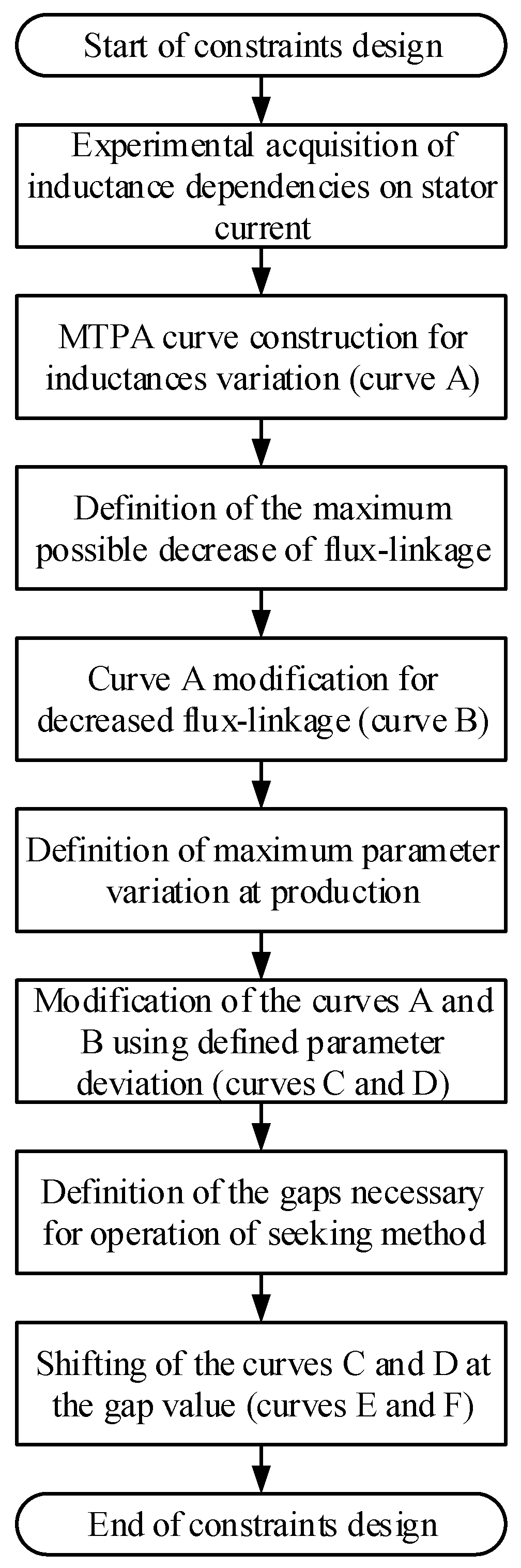
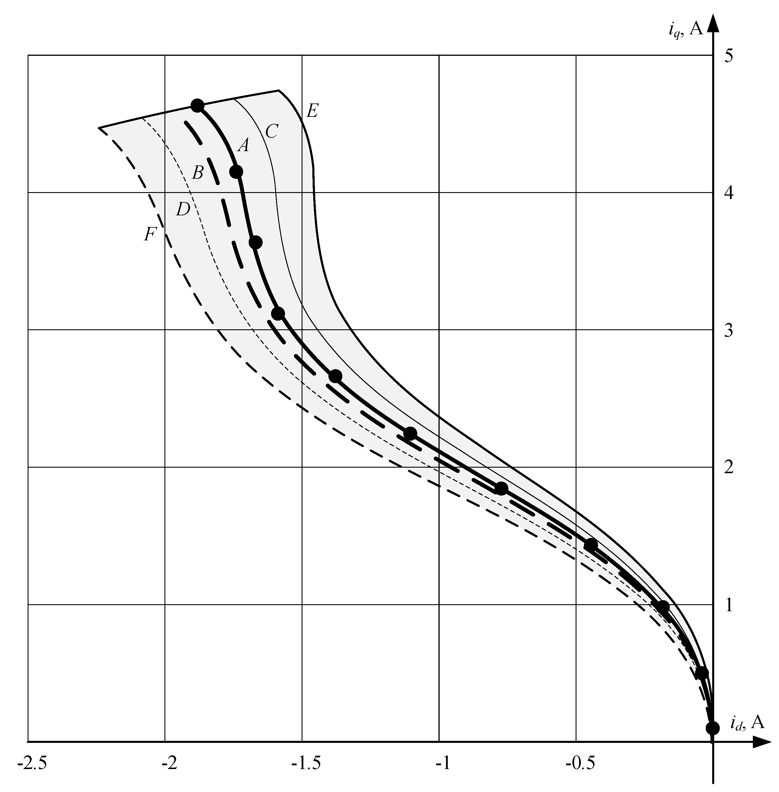
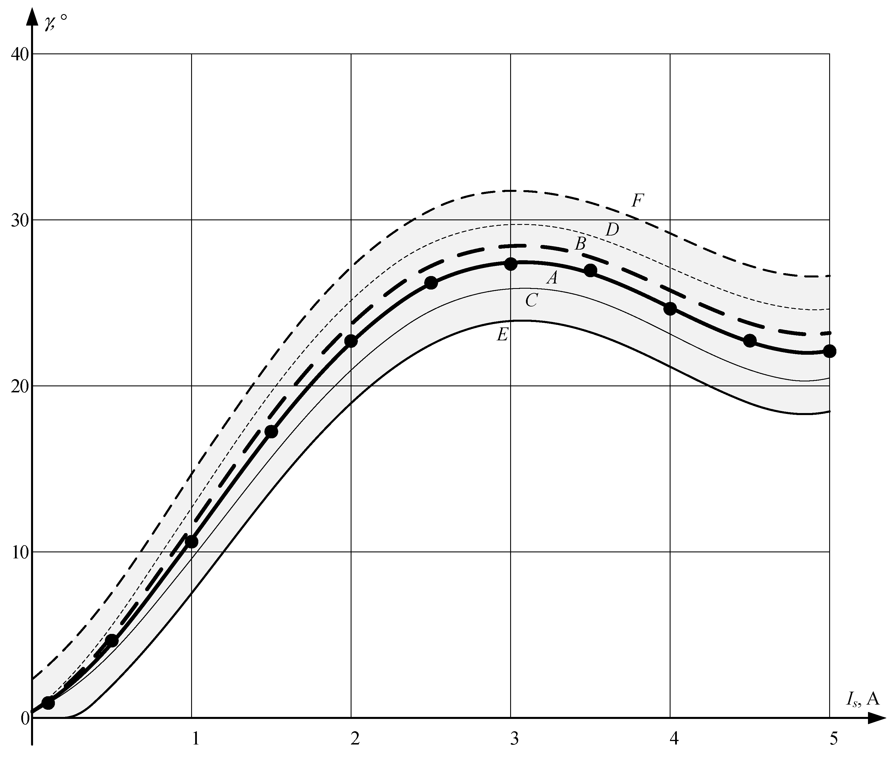
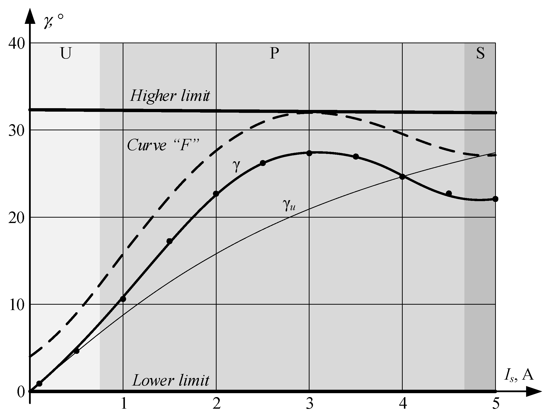
4. Proposed Method for Design of Constraints

In order to solve the abovementioned problems, a new algorithm for the design of constraints for MTPA seeking techniques has been developed and considered in this paper. This idea will be explained using a test motor as an example and the corresponding constraints for an MTPA trajectory seeking algorithm are constructed. For higher convenience, the MTPA trajectories are designed in the idiq plane and for an MTPA angle γ, simultaneously. Therefore, the proposed technique can be easily adapted for control schemes involving MTPA formulation based on the Equations (6)–(8).
The proposed method is demonstrated in Figure 9 and includes the following steps. Initially, the direct and quadrature inductances variations with the stator current increase are measured, and the corresponding dependence of the inductance difference ΔL is calculated. These measurements are repeated for several motor samples and the resulting data are averaged. After that, the MTPA trajectory for the measured inductances is plotted, i.e., curve “A” in Figure 10 and Figure 11. At the next stage, the maximum possible decrease of the rotor flux-linkage is calculated, and the corresponding curve is plotted. For the test motor, which uses NdFeB magnets, the motor designers estimated the maximum temperature decrease is 3% and the maximum aging and demagnetization degradation is 5%, which results in a maximum reduction of 8%. The corresponding MTPA trajectories are depicted as curve “B” in Figure 10 and Figure 11. After that, the maximum possible deviation of motor parameters from their rated values at the stage of production is taken into account. This deviation is not significant and is caused by assembling inaccuracies, materials from different lots, etc. The factory quality assurance engineers reported that the possible variation of the flux-linkage is less than 1%, while the inductance deviation may be as high as 12%. At the same time, the character of inductance dependencies, demonstrated in Figure 6, is almost unchanged and deviation results only in scaling of those curves. At the next stage, the previously constructed curves “A” and “B” are modified using obtained information on the maximum deviation of motor parameters, which results in curves “C” and “D” in Figure 10 and Figure 11, respectively. These curves define the zone, limiting the possible location of the true MTPA trajectory for all motors in the series.
After the area containing the MTPA trajectory is defined, it must be extended with the gaps necessary for the proper operation of the MTPA seeking technique and stable detection of the torque extremum corresponding to the MTPA condition. The term “gap” relates to the disturbed parameter, and its dimension is the same; however, implementation of the constraints depends on the MTPA technique and typically is performed in the idiq or Isγ planes. These gaps depend on the exact MTPA tracking algorithm and have to enclose the area, which fully includes border trajectories and deviation from them caused by the injection of additional signals. The MTPA algorithm involved in the experiments, was a seeking technique, which permanently disturbs the phase angle of the stator current and measures its amplitude, trying to minimize it [33]. This algorithm can stably detect the maximum of the torque curve, when it lies in the middle of the disturbance step Δγ. Therefore, the gap, necessary for proper operation of this technique, which can guarantee the correct detection of extremum, is half of the disturbance angle, which was 2°. Thus, the curves “C” and “D” have to be moved at this gap angle, which results in “E” and “F” in Figure 10 and Figure 11, respectively. These curves, “E” and “F”, define our desired constraints, which can improve the performance of seeking an MTPA algorithm.
These curves could be implemented as a look-up table (LUT), approximating polynomial or a set of splines; however, the best way of approximation depends on the complexity of the constraint curves.
The proposed method of constraints design was developed for operation with a series of motors, where inductances could be measured in advance. However, it could be easily adapted for self-commissioning drives, which operate without prior knowledge of motor parameters. In this case, at the stage of parameter identification, the control system has to additionally identify dependence of the inductance difference on the stator current. After that, the curve “A” can be constructed. The construction of the curve “A” is made using data from Figure 6 by substituting inductances as functions from the current magnitude and the current magnitude itself into (6). Then evaluation of (5) allows to obtain both current components in idiq plane. If it is desired to evaluate MTPA angle γ with respect to the current magnitude, then Equation (9) is used.
At the next stage, the maximum variation of the flux-linkage has to be defined. Since this information is unavailable, the high-border estimation can be used: 12–15% for NdFeB magnets and 25–30% for ferrite magnets. Thus, the curve “B” can be constructed. The higher margin values increase response time of MTPA algorithms; therefore, it is desired to decrease the margins as much as possible. The recommended values of the flux linkage deviation came from the worst motor prototypes known to the authors and cover the overwhelming majority of motor drives. However, if a developer is confident that the maximum possible deviation of the flux linkage is less than the recommended values, the margins have to be decreased. Since self-commissioning routine tunes the drive for operation with the exact sample of motor, the curves “C” and “D”, which define motor parameter variation at manufacturing, could be skipped. After that, the curves “E” and “F” can be constructed by moving the curves “A” and “B” at the gap angle, which is equal to the half of disturbance angle for the test algorithm.

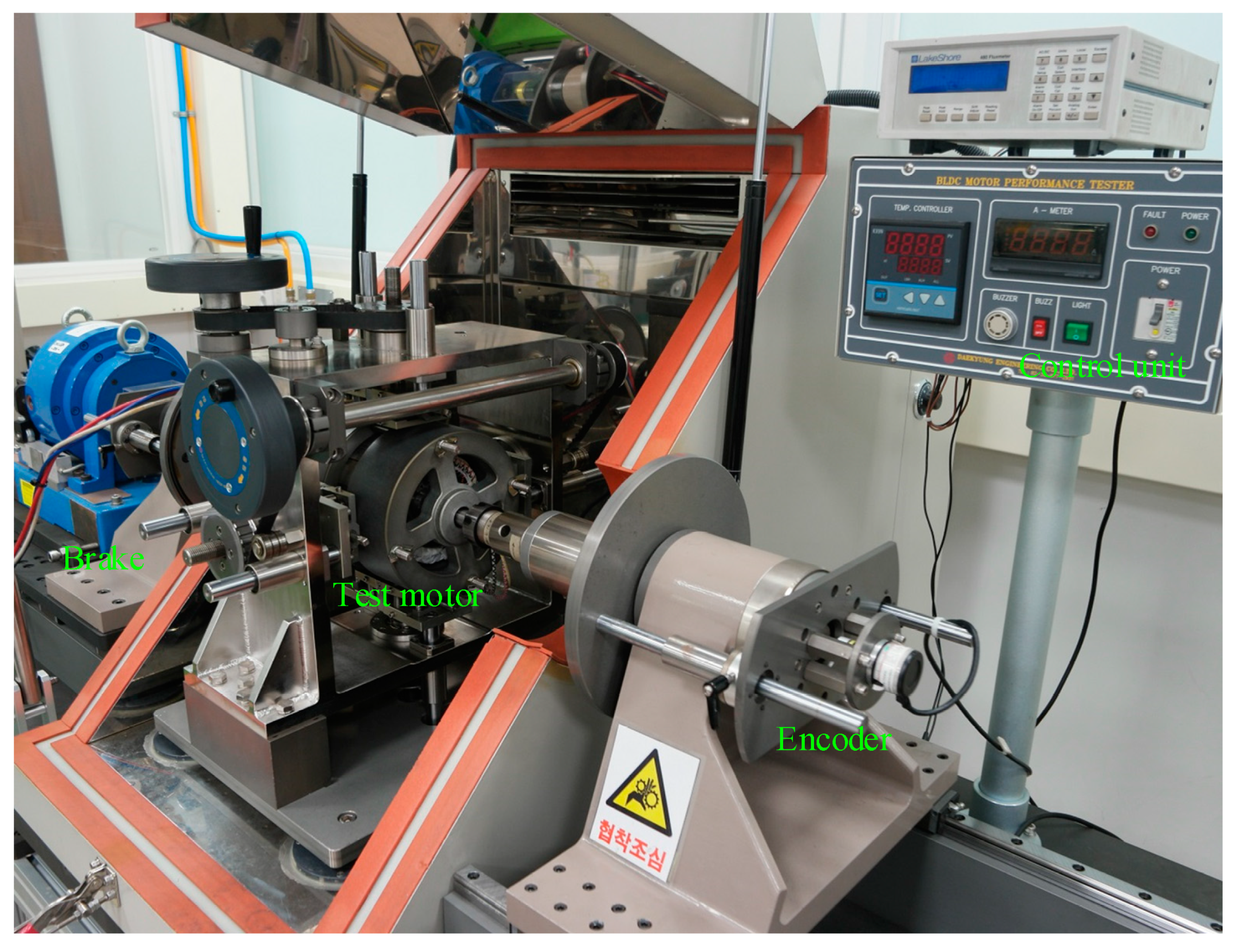
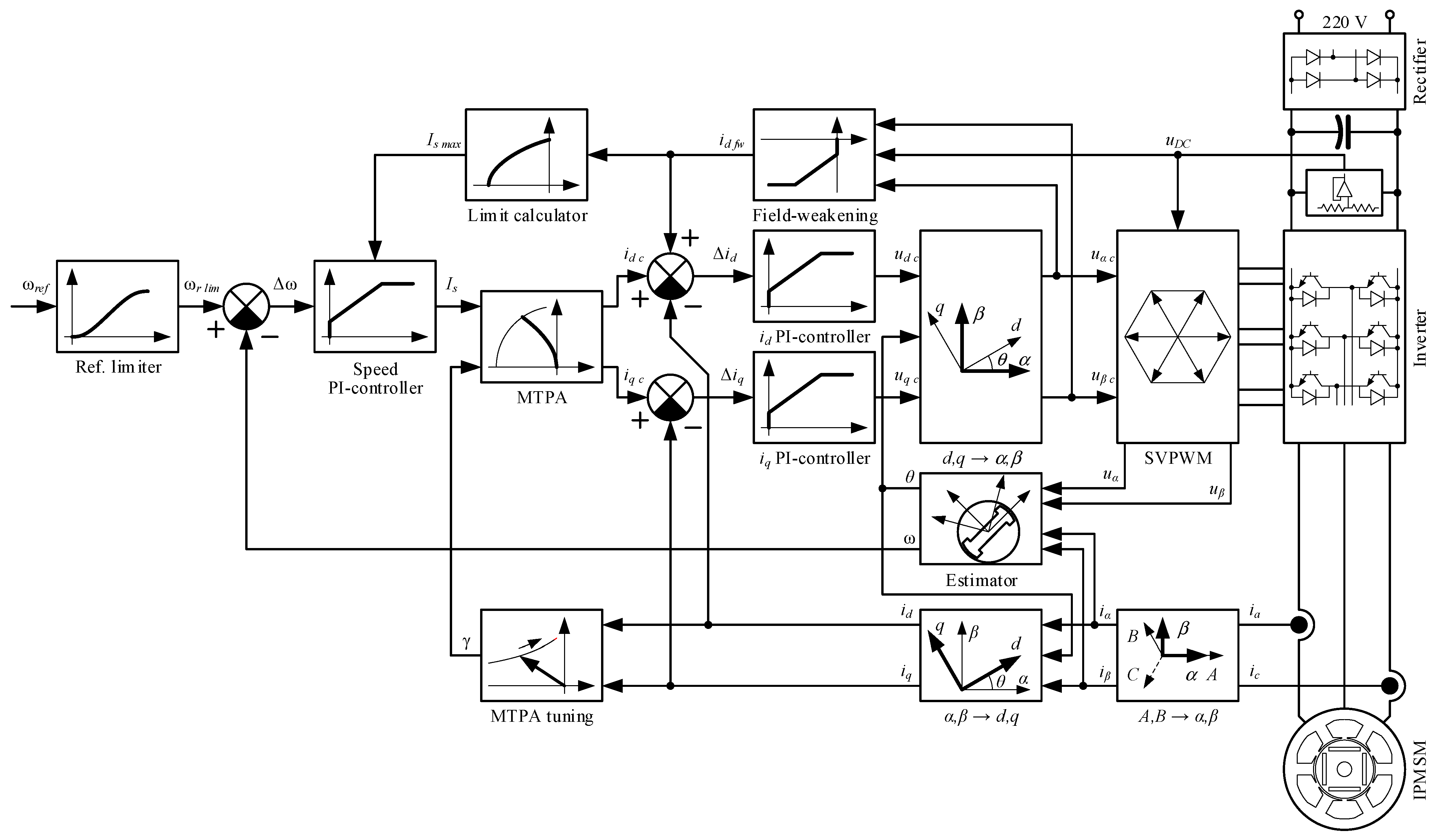
5. Experimental Setup

The experimental verification of the proposed algorithm was performed using the test rig demonstrated in Figure 12. It included a prototype of the three phase PMSM developed for rotary and reciprocating compressors, the rated parameters are shown in Table 1. However, motor direct and quadrature inductances strongly depend on the stator current and vary as depicted in Figure 6.
The IPMSM control system implemented for verification of the proposed algorithm, was taken from a commercial motor drive discussed in [46] (Figure 13). It performs a sensorless control of IPM motors, using a back-EMF based speed and position estimation technique discussed in [47]. In order to exclude reverse rotation at the start, the estimator is enhanced with an initial rotor position estimation algorithm [48]. The performance of the estimation algorithm was verified with the help of an incremental position encoder [49,50], which demonstrated that it operates at speeds over 10 Hz with the maximum estimation error of 3~4 electrical degrees. Since the control system was designed for operation with compressors, it was enhanced with a silent stoppage algorithm considered in [51].
The control scheme contains an outer speed loop and inner current loops in the synchronous reference frame, where the rotor speed and position are provided by the estimation algorithm. The information on the motor electrical signals is provided by the DC-link voltage and two shunt-based current sensors, placed at the bottom legs of the inverter.
The IPMSM control system includes a field-weakening algorithm, which increases the maximum operation speed by up to +50% of the rated one by demagnetizing the rotor field with a negative id current. The motor drive includes an adaptive MTPA control algorithm, required to increase efficiency. This algorithm uses a seeking technique, which was considered in [31]; therefore, this method for MTPA control can be used for the experimental validation of the proposed idea.
The motor under test was connected with a Magtrol water cooling power brake 1-PB-65 capable of providing load torque up to 10 N∙m. This power brake was controlled by the Magtrol DSP6001 dynamometer controller, which received commands from the computer and reported speed and torque. This load equipment provided low-ripple and precise torque application, which is necessary for the accurate measurements of speed-torque characteristics of the motor drive. The electrical signals were measured by the Yokogawa DL 850 oscilloscope, capable of operating with raw data and oscillograms and a Yokogawa WT-1800E power analyzer used for measurements of power and efficiency.
The inverter involved in these experiments was a commercial device designed for the control of rotary compressors of air conditioners. It was based on the FSBB15CH60F (15 A/600 V) Fairchild smart power module and designated for operation in 220 V (50/60) Hz standard grids. This inverter had a conventional structure for low-cost applications, which involved two shunt-based current sensors in the inverter legs and one voltage sensor in the DC-link. The signals from the sensors were pre-amplified by internal operational amplifiers of the microcontroller and then processed by a 12-bit ADC. The control system of the inverter used in the experiments included the iHart i910 Cortex M3 core microcontroller operating at 80 MHz and controlled the inverter switches at 10 kHz. The experimental sample of the inverter was extended with an RS-232 communication interface used for the connection with the computer in order to send commands and monitor the internal data.

6. Experimental Results
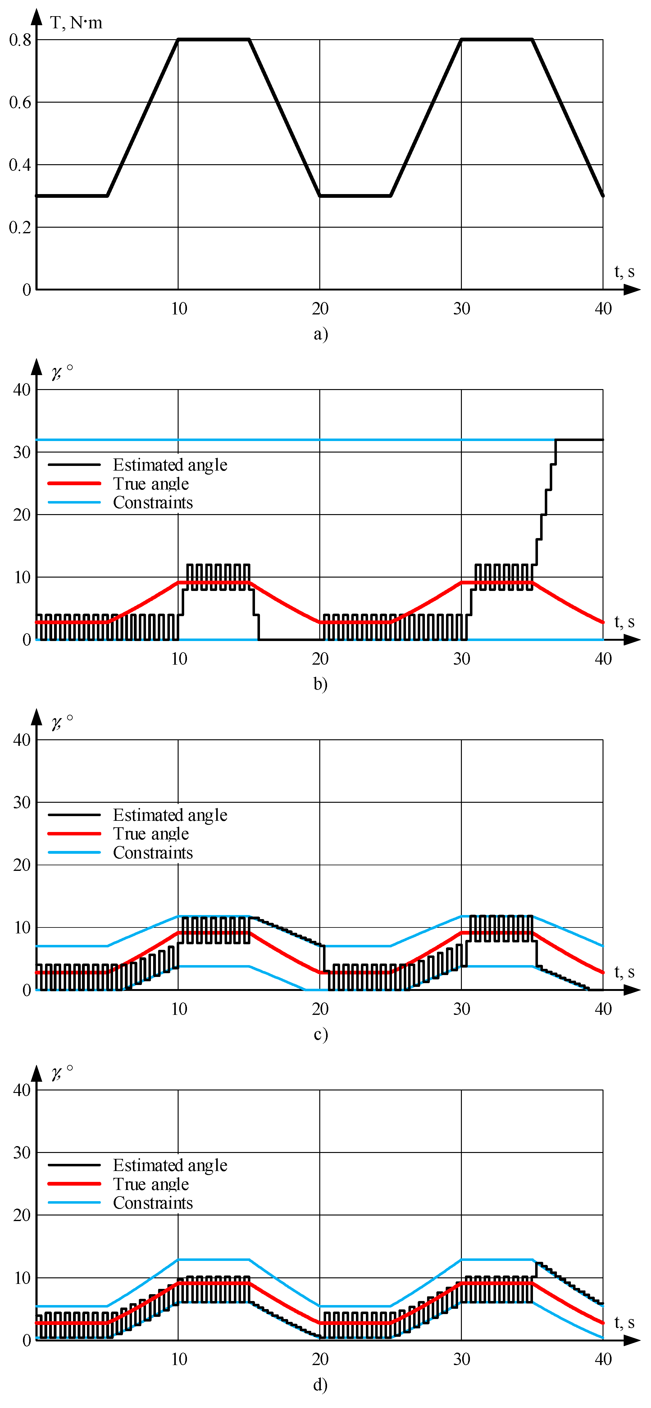
In order to check the performance of the proposed method, a number of experiments have been carried out. The seeking MTPA algorithm used for testing, involves the PandO principle and permanently disturbs the phase of the stator current, analyzing changes of its magnitude. Thus, the constraints for this technique were set as curves “E” and “F” from Figure 11 and implemented using LUT, containing 33 points for each curve with linear interpolation between them. The disturbance angle Δγ used by the seeking algorithm was 4° and its calculation step N was selected as 20 electrical revolutions. The maximum calculation time Tmax of the MTPA tuning algorithm was set to 0.5 s, which results in a minimum motor speed, at which an MTPA tuning algorithm can operate:
n min = 60 N p T max = 60 20 3 0.5 = 800   rpm
This speed perfectly fits the requirements of the control system of compressors, where the operational area requires speeds over 900~1200 rpm.
In order to check the dynamic behavior of the seeking algorithm with different constraints, the load torque contained equal intervals of constant load, and positive and negative ramps. For the performance evaluation of the proposed idea, the measurements were performed at the lowest allowed operational speed, which is the most difficult condition for the seeking algorithms. Despite the minimum operational speed of the selected seeking technique being 800 rpm, the experiments were conducted at 1200 rpm, which is the minimum permitted speed for reciprocating the compressors utilizing the considering drive. After obtaining the data on estimated MTPA angle, the efficiency of the motor was measured in operation of the MTPA-seeking algorithm with the considered sets of constraints. In this test, the data were averaged at the interval of ten load periods (200 s), which minimizes the impact of random perturbations.
For comparison of the developed method with the prior art, the constraints were designed according to their recommendations.

6.1. Fixed Limits

In this method the constraints for the stator current phase were selected to consider the case where motor parameters are unknown and self-commissioning is not performed. The fixed predefined numbers equal to the theoretical minimum and maximum values where selected. As can be observed from Figure 11, the minimum value of the MTPA angle γ is 0°, whereas the maximum angle is defined by curve “F” (about 32°). For a pure reluctance motor the maximum angle cannot exceed 45° if it is desired to cover 100% of all motor designs. These angles were selected as the limits for the variation of the seeking algorithm disturbance factor. These limits are depicted in Figure 14 together with the MTPA trajectories and curves used for the design.

6.2. Rated MTPA Curve with Gaps

According to this method, the constraints are designed using the MTPA curve for rated motor parameters, which is shifted to higher and lower directions at the fixed gap. In this experiment, the gap was selected as the seeking algorithm disturbance angle Δγ, which is equal to 4°. At the same time, the MTPA angle for the test motor may not be negative; therefore, the lower limit is set to zero in this area, where parallel shift of the rated MTPA curve resulted in negative values. These limits are depicted in Figure 15 together with the MTPA trajectories and curves used for design.

6.3. Operation at Low Load

In this experiment, the performance of the proposed technique was evaluated and compared with existing algorithms at low loads, where the motor was not saturated (zone “U”). Two cycles of the load torque used in this experiment are depicted in Figure 16a. The performance of seeking the algorithm operation with “Fixed limits”, “Rated MTPA curve with gaps” and proposed constraints are demonstrated in Figure 16b–d, respectively. The measured efficiency for these constraint sets was: 47.4%, 51.9% and 52.1%, respectively.

6.4. Operation at Medium Load

In this experiment, the performance of the proposed technique was evaluated and compared with existing algorithms at low loads, where the motor was partly saturated (zone “P”). Two cycles of the load torque used in this experiment are depicted in Figure 17a. The performance of the seeking algorithm operation with “Fixed limits”, “Rated MTPA curve with gaps” and proposed constraints are demonstrated in Figure 17b–d, respectively. The measured efficiency for these constraint sets was: 85.2%, 87.1% and 88.4%, respectively.

6.5. Operation at High Load

In this experiment, the performance of the proposed technique was evaluated and compared with existing algorithms at low loads, where the motor was highly saturated (zone “S”). Two cycles of the load torque used in this experiment are depicted in Figure 18a. The performance of the seeking algorithm operation with “Fixed limits”, “Rated MTPA curve with gaps” and proposed constraints are demonstrated in Figure 18b–d, respectively. The measured efficiency for these constraint sets was: 85.6%, 86.1% and 86.3%, respectively.

7. Discussion

It is clearly observable from the provided experimental results, that the seeking algorithm does not operate properly at transients. Furthermore, its behavior depends on the sign of the torque derivative: if it is positive, the estimated angle fluctuates near its previous value, if the derivative is negative, the estimated angle goes to a lower or higher limit, depending on the direction at the previous stage. As a result, the constraints design plays an important role in the dynamic performance by limiting this uncontrollable change.
The experimental results showed that the operation of the seeking algorithm with fixed constraints results in a poorer dynamic and significantly decreases motor efficiency in dynamic modes. Therefore, this method may be recommended only for simple systems, which mainly operate under constant load torque.
The seeking algorithm with constraints designed using a rated MTPA curve with gaps, demonstrates better dynamic and efficiency than the same algorithm with the fixed constraints. It demonstrates acceptable results in the regions, where the true MTPA curve is close to the rated curve. However, its operation is not optimal at the loads, where the true MTPA trajectory significantly deviates from the rated MTPA curve and leaves the area enclosed by the constraints. The experimental motor is a good example of this case, which is illustrated by Figure 17. As a result, this method of constraints design can be suggested for motors, where the MTPA trajectory does not significantly deviate from the rated MTPA trajectory.
It can be observed that the operation of the seeking algorithm with constraints, which is designed according to the proposed method, demonstrated better efficiency and dynamic behavior. Therefore, it is recommended for the motor drives, where the motor was designed for operation with considerable saturation and where the MTPA curve significantly deviates from the curve constructed for the unsaturated parameters.
At the same time, it should be noted that the operation of the seeking algorithm with a different set of constraints at a constant or slowly changing load torque is similar and they differ only in dynamic.

8. Conclusions

This paper proposes a new method for constraints design for MTPA seeking techniques. This algorithm takes into account possible motor parameter variation due to operational conditions and deviation at the stage of production. The authors considered existing approaches to constraints design and experimentally compared performance of the MTPA-seeking algorithm with constraints designed according to existing and proposed algorithms. It was shown that the proposed method improves efficiency and dynamic operation of MTPA seeking techniques, especially for the motors, which operate in the saturation zone and whose MTPA curve significantly deviates from the MTPA trajectory calculated for the unsaturated parameters.

Author Contributions

Conceptualization A.D.; methodology A.A.; software A.D.; validation A.D. and A.A.; formal analysis A.D. and A.A.; investigation A.D.; resources A.A.; data curation A.A.; writing—original draft preparation A.D.; writing—review and editing A.D. and A.A.; visualization A.D.; supervision A.D.; project administration A.D.; funding acquisition A.A. All authors have read and agreed to the published version of the manuscript.

Funding

This research is supported by the Russian Science Foundation grant (Project №21-19-00696).

Institutional Review Board Statement

Not applicable.

Informed Consent Statement

Not applicable.

Data Availability Statement

Not applicable.

Conflicts of Interest

The authors declare no conflict of interest.

References

  1. Sun, J.; Lin, C.; Xing, J.; Jiang, X. Online MTPA Trajectory Tracking of IPMSM Based on a Novel Torque Control Strategy. Energies 2019, 12, 3261. [Google Scholar] [CrossRef] [Green Version]
  2. Tinazzi, F.; Zigliotto, M. Torque Estimation in High-Efficency IPM Synchronous Motor Drives. IEEE Trans. Energy Convers. 2015, 30, 983–990. [Google Scholar] [CrossRef]
  3. Preindl, M.; Bolognani, S. Optimal State Reference Computation with Constrained MTPA Criterion for PM Motor Drives. IEEE Trans. Power Electron. 2015, 30, 4524–4535. [Google Scholar] [CrossRef]
  4. Inoue, T.; Inoue, Y.; Morimoto, S.; Sanada, M. Maximum Torque Per Ampere Control of a Direct Torque-Controlled PMSM in a Stator Flux Linkage Synchronous Frame. IEEE Trans. Ind. Appl. 2016, 52, 2360–2367. [Google Scholar] [CrossRef]
  5. Decker, S.; Brodatzki, M.; Bachowsky, B.; Schmitz-Rode, B.; Liske, A.; Braun, M.; Hiller, M. Predictive Trajectory Control with Online MTPA Calculation and Minimization of the Inner Torque Ripple for Permanent-Magnet Synchronous Machines. Energies 2020, 13, 5327. [Google Scholar] [CrossRef]
  6. Li, Z.; Li, H. MTPA control of PMSM system considering saturation and cross-coupling. In Proceedings of the 15th International Conference on Electrical Machines and Systems, Sapporo, Japan, 11–24 October 2012; pp. 1–6. [Google Scholar]
  7. Miao, Y.; Miao, Y.; Ge, H.; Preindl, M.; Ye, J.; Cheng, B.; Emadi, A. MTPA Fitting and Torque Estimation Technique Based on a New Flux-Linkage Model for Interior-Permanent-Magnet Synchronous Machines. IEEE Trans. Ind. Appl. 2017, 53, 5451–5460. [Google Scholar] [CrossRef]
  8. Carraro, M.; Tinazzi, F.; Zigliotto, M. Estimation of the direct-axis inductance in PM synchronous motor drives at standstill. In Proceedings of the 2013 IEEE International Conference on Industrial Technology, Cape Town, South Africa, 25–28 February 2013; pp. 313–318. [Google Scholar]
  9. Kim, H.B.; Hartwig, J.; Lorenz, R.D. Using on-line parameter estimation to improve efficiency of IPM machine drives. In Proceedings of the IEEE 33rd Power Electronics Specialists Conference, Cairns, Australia, 23–27 June 2002; pp. 815–820. [Google Scholar]
  10. Phowanna, P.; Boonto, S.; Konghirun, M. Online parameter identification method for IPMSM drive with MTPA. In Proceedings of the 18th International Conference on Electrical Machines and Systems, Pattaya City, Thailand, 25–28 October 2015; pp. 1–6. [Google Scholar]
  11. Feng, G.; Lai, C.; Mukherjee, K.; Kar, N.C. Online PMSM Magnet Flux-Linkage Estimation for Rotor Magnet Condition Monitoring Using Measured Speed Harmonics. IEEE Trans. Ind. Appl. 2017, 53, 2786–2794. [Google Scholar] [CrossRef]
  12. Xiao, S.; Griffo, A. PWM-based flux linkage and rotor temperature estimations for permanent magnet synchronous machines. IEEE Trans. Energy Convers. 2020, 35, 6061–6069. [Google Scholar] [CrossRef]
  13. Liu, Q.; Hameyer, K. High-Performance Adaptive Torque Control for an IPMSM With Real-Time MTPA Operation. IEEE Trans. Energy Convers. 2017, 32, 571–581. [Google Scholar] [CrossRef]
  14. Shinohara, A.; Inoue, Y.; Morimoto, S.; Sanada, M. Maximum Torque Per Ampere Control in Stator Flux Linkage Synchronous Frame for DTC-Based PMSM Drives Without Using q-Axis Inductance. IEEE Trans. Ind. Appl. 2017, 53, 3663–3671. [Google Scholar] [CrossRef]
  15. Mohamed, Y.A.R.I.; Lee, T.K. Adaptive self-tuning MTPA vector controller for IPMSM drive system. IEEE Trans. Energy Convers. 2006, 21, 636–644. [Google Scholar] [CrossRef]
  16. Bolognani, S.; Sgarbossa, L.; Zordan, M. Self-tuning of MTPA current vector generation scheme in IPM synchronous motor drives. In Proceedings of the European Conference on Power Electronics and Applications, Aalborg, Denmark, 2–5 September 2007; pp. 1–10. [Google Scholar]
  17. Bolognani, S.; Petrella, R.; Prearo, A.; Sgarbossa, L. Automatic Tracking of MTPA Trajectory in IPM Motor Drives Based on AC Current Injection. IEEE Trans. Ind. Appl. 2010, 47, 105–114. [Google Scholar] [CrossRef]
  18. Antonello, R.; Carraro, M.; Zigliotto, M. Maximum-torque-per-ampere operation of anisotropic synchronous permanent-magnet motors based on extremum seeking control. IEEE Trans. Ind. Electron. 2014, 61, 5086–5093. [Google Scholar] [CrossRef]
  19. Chen, Q.; Gu, L.; Lin, Z.; Liu, G. Extension of Space-Vector-Signal-Injection Based MTPA Control into SVPWM Fault-Tolerant Operation for Five-Phase IPMSM. IEEE Trans. Ind. Electron. 2019, 66, 6089–6101. [Google Scholar] [CrossRef]
  20. Yousefi-Talouki, A.; Pescetto, P.; Pellegrino, G.-M.L.; Boldea, I. Combined Active Flux and High-Frequency Injection Methods for Sensorless Direct-Flux Vector Control of Synchronous Reluctance Machines. IEEE Trans. Power Electron. 2017, 33, 2447–2457. [Google Scholar] [CrossRef]
  21. Lee, K.; Han, Y. MTPA control strategy based on signal injection for V/f scalar-controlled surface permanent magnet synchronous machine drives. IEEE Access 2020, 8, 96036–96044. [Google Scholar] [CrossRef]
  22. Sue, S.M.; Hung, T.W.; Liaw, J.H.; Li, Y.F.; Sun, C.Y. A new MTPA control strategy for sensorless V/f controlled PMSM drives. In Proceedings of the 6th IEEE Conference on Industrial Electronics and Applications, Beijing, China, 21–23 June 2011; pp. 1–5. [Google Scholar]
  23. Sun, T.; Koc, M.; Wang, J. MTPA Control of IPMSM Drives Based on Virtual Signal Injection Considering Machine Parameter Variations. IEEE Trans. Ind. Electron. 2018, 65, 6089–6098. [Google Scholar] [CrossRef] [Green Version]
  24. Sun, T.; Wang, J.; Chen, X. Maximum torque per ampere (MTPA) control for interior permanent magnet synchronous machine drives based on virtual signal injection. IEEE Trans. Power Electron. 2015, 30, 5036–5045. [Google Scholar] [CrossRef]
  25. Sun, T.; Wang, J.; Koc, M. On Accuracy of Virtual Signal Injection based MTPA Operation of Interior Permanent Magnet Synchronous Machine Drives. IEEE Trans. Power Electron. 2017, 32, 7405–7408. [Google Scholar] [CrossRef]
  26. Tang, Q.; Shen, A.; Luo, P.; Shen, H.; Li, W.; He, X. IPMSMs Sensorless MTPA Control Based on Virtual q-Axis Inductance by Using Virtual High-Frequency Signal Injection. IEEE Trans. Ind. Electron. 2019, 67, 136–146. [Google Scholar] [CrossRef]
  27. Wang, J.; Huang, X.Y.; Fang, Y.T.; Niu, F.; Wu, L.J. Power Perturbation Based Virtual Signal Injection Control of MTPA for IPMSM Drive System. In Proceedings of the 13th International Conference on Electrical Machines, Alexandroupoli, Greece, 3–6 September 2018; pp. 1–6. [Google Scholar]
  28. Chen, Q.; Zhao, W.; Liu, G.; Lin, Z. Extension of Virtual-Signal-Injection-Based MTPA Control for Five-Phase IPMSM Into Fault-Tolerant Operation. IEEE Trans. Ind. Electron. 2018, 66, 944–955. [Google Scholar] [CrossRef]
  29. Sun, T.; Long, L.; Yang, R.; Li, K.; Liang, J. Extended Virtual Signal Injection Control for MTPA Operation of IPMSM Drives with Online Derivative Term Estimation. IEEE Trans. Power Electron. 2020, 35, 6061–6069. [Google Scholar]
  30. Niazi, P.; Toliyat, H.A.; Goodarzi, A. Robust Maximum Torque per Ampere (MTPA) Control of PM-Assisted SynRM for Traction Applications. IEEE Trans. Veh. Technol. 2007, 56, 1538–1545. [Google Scholar] [CrossRef]
  31. Dianov, A.; Anuchin, A. Adaptive maximum torque per ampere control of sensorless permanent magnet motor drives. Energies 2020, 13, 5071. [Google Scholar] [CrossRef]
  32. Dianov, A.; Anuchin, A. Adaptive maximum torque per ampere control for IPMSM drives with load varying over mechanical revolution. IEEE J. Emerg. Sel. Top. Power Electron. 2020. [Google Scholar] [CrossRef]
  33. Dianov, A.; Anuchin, A.; Bodrov, A. Robust MTPA Control for Steady State Operation of Low-Cost IPMSM Drives. IEEE J. Emerg. Sel. Top. Ind. Electron. 2021. [Google Scholar] [CrossRef]
  34. Dianov, A.; Young-Kwan, K.; Sang-Joon, L.; Sang-Taek, L. Robust self-tuning MTPA algorithm for IPMSM drives. In Proceedings of the 34th Annual Conference of IEEE Industrial Electronics, Orlando, FL, USA, 10–13 November 2008; pp. 1355–1360. [Google Scholar]
  35. Wang, G.; Li, Z.; Zhang, G.; Yu, Y.; Xu, D. Quadrature PLL-Based High-Order Sliding-Mode Observer for IPMSM Sensorless Control with Online MTPA Control Strategy. IEEE Trans. Energy Convers. 2012, 28, 214–224. [Google Scholar] [CrossRef]
  36. Chaoui, H.; Okoye, O.; Khayamy, M. Current sensorless MTPA for IPMSM drives. IEEE/ASME Trans. Mechatron. 2017, 22, 1585–1593. [Google Scholar] [CrossRef]
  37. Lin, F.-J.; Huang, M.-S.; Chen, S.-G.; Hsu, C.-W. Intelligent Maximum Torque per Ampere Tracking Control of Synchronous Reluctance Motor Using Recurrent Legendre Fuzzy Neural Network. IEEE Trans. Power Electron. 2019, 34, 12080–12094. [Google Scholar] [CrossRef]
  38. Daryabeigi, E.; Zarchi, H.A.; Markadeh, G.A.; Soltani, J.; Blaabjerg, F. Online MTPA Control Approach for Synchronous Reluctance Motor Drives Based on Emotional Controller. IEEE Trans. Power Electron. 2014, 30, 2157–2166. [Google Scholar] [CrossRef]
  39. Krstic, M. Extremum seeking control. In Encyclopedia of Systems and Control; Baillieul, J., Samad, T., Eds.; Springer: London, UK, 2014. [Google Scholar]
  40. Joo, K.J.; Park, J.S.; Lee, J. Study on Reduced Cost of Non-Salient Machine System Using MTPA Angle Pre-Compensation Method Based on EEMF Sensorless Control. Energies 2018, 11, 1425. [Google Scholar] [CrossRef] [Green Version]
  41. Guo, Q.; Zhang, C.; Li, L.; Zhang, J.; Wang, M. Maximum Efficiency per Torque Control of Permanent-Magnet Synchronous Machines. Appl. Sci. 2016, 6, 425. [Google Scholar] [CrossRef] [Green Version]
  42. Baek, S.K.; Oh, H.K.; Park, J.H.; Shin, Y.J.; Kim, S.W. Evaluation of Efficient Operation for Electromechanical Brake Using Maximum Torque per Ampere Control. Energies 2019, 12, 1869. [Google Scholar] [CrossRef] [Green Version]
  43. Ye, M.; Shi, T.; Wang, H.; Li, X.; Xia, C. Sensorless-MTPA Control of Permanent Magnet Synchronous Motor Based on an Adaptive Sliding Mode Observer. Energies 2019, 12, 3773. [Google Scholar] [CrossRef] [Green Version]
  44. Dianov, A.; Su, K.N.; Kwan, K.Y. Future Drives of Home Appliances: Elimination of the Electrolytic DC-Link Capacitor in Electrical Drives for Home Appliances. IEEE Ind. Electron. Mag. 2015, 9, 10–18. [Google Scholar] [CrossRef]
  45. Li, K.; Wang, Y. Maximum Torque Per Ampere (MTPA) Control for IPMSM Drives Based on a Variable-Equivalent-Parameter MTPA Control Law. IEEE Trans. Power Electron. 2019, 34, 7092–7102. [Google Scholar] [CrossRef]
  46. Dianov, A. Estimation of the mechanical position of reciprocating compressor for silent stoppage. IEEE Open J. Power Electron. 2020, 1, 64–73. [Google Scholar] [CrossRef]
  47. Dianov, A.; Kim, N.S.; Lim, S.M. Sensorless starting of direct drive horizontal axis washing machines. J. Int. Conf. Electr. Mach. Syst. 2014, 3, 148–154. [Google Scholar] [CrossRef] [Green Version]
  48. Dianov, A.; Anuchin, A.S.; Kozachenko, V.F. Initial Rotor Position Detection of PM Motors. In Proceedings of the EPE Power Electronics and Motion Control Conference, Riga, Latvia, 2–4 September 2004; pp. 1–6. [Google Scholar]
  49. Anuchin, A.; Dianov, A.; Briz, F. Synchronous Constant Elapsed Time Speed Estimation Using Incremental Encoders. IEEE/ASME Trans. Mechatron. 2019, 24, 1893–1901. [Google Scholar] [CrossRef]
  50. Anuchin, A.; Dianov, A.; Shpak, D.; Astakhova, V.; Fedorova, K. Speed estimation algorithm with specified bandwidth for incremental position encoder. In Proceedings of the 17th International Conference on Mechatronics—Mechatronika, Prague, Czech Republic, 7–9 December 2016; pp. 1–6. [Google Scholar]
  51. Dianov, A. Stoppage noise reduction of reciprocating compressors. IEEE Trans. Ind. Appl. 2021, 57, 4376–4384. [Google Scholar] [CrossRef]
Figure 1. Simplified design of IPMSM.
Mathematics 09 02785 g001
Figure 2. MTPA trajectory in idiq plane.
Mathematics 09 02785 g002
Figure 3. Dependence of the MTPA angle γ on the stator current amplitude.
Mathematics 09 02785 g003
Figure 4. MTPA trajectories in idiq plane at different flux-linkages.
Mathematics 09 02785 g004
Figure 5. Dependence of the MTPA angles γ on the stator current amplitude at different flux-linkages.
Mathematics 09 02785 g005
Figure 6. Motor inductances vs. current at the MTPA trajectory.
Mathematics 09 02785 g006
Figure 7. Test motor MTPA trajectories in idiq plane.
Mathematics 09 02785 g007
Figure 8. Dependence of the test motor MTPA angles γ with respect to the stator current amplitude.
Mathematics 09 02785 g008
Figure 9. Flowchart of constraints design algorithm.
Mathematics 09 02785 g009
Figure 10. MTPA constraints design in idiq plane.
Mathematics 09 02785 g010
Figure 11. MTPA constraints design for MTPA angle γ.
Mathematics 09 02785 g011
Figure 12. Experimental setup.
Mathematics 09 02785 g012
Figure 13. Control block diagram of the IPM motor drive with seeking MTPA algorithm.
Mathematics 09 02785 g013
Figure 14. Constraints design for MTPA angle γ using fixed limits.
Mathematics 09 02785 g014
Figure 15. Constraints design for MTPA angle γ using rated MTPA curve with gaps.
Mathematics 09 02785 g015
Figure 16. Operation of seeking algorithm with different constraints at low load: (a) Torque profile; (b) Fixed limits; (c) Rated MTPA curve with gaps; and (d) Proposed technique.
Mathematics 09 02785 g016
Figure 17. Operation of the seeking algorithm with different constraints at medium load. (a) Torque profile; (b) Fixed limits; (c) Rated MTPA curve with gaps; and (d) Proposed technique.
Mathematics 09 02785 g017
Figure 18. Operation of the seeking algorithm with different constraints at high load. (a) Torque profile; (b) Fixed limits; (c) Rated MTPA curve with gaps; and (d) Proposed technique.
Mathematics 09 02785 g018
Table 1. Motor rated parameters.
ParameterValue
Number of pole pairsp = 3
Rated power, kW1.4
Rated torque, N∙m5.0
Phase resistance, Ω2.05
d-axis inductance, mH83
q-axis inductance, mH115
Back-EMF constant, V·s/rad0.2
Publisher’s Note: MDPI stays neutral with regard to jurisdictional claims in published maps and institutional affiliations.

