Article

Numerical Study on Hydrogen–Gasoline Dual-Fuel Spark Ignition Engine

by
Mahdi Aghahasani
1,
Ayat Gharehghani
1,*,
Amin Mahmoudzadeh Andwari
2,3,*,
Maciej Mikulski
4,
Apostolos Pesyridis
3,5,
Thanos Megaritis
3 and
Juho Könnö
2
1
School of Mechanical Engineering, Iran University of Science and Technology, Narmak, Tehran 13114-16846, Iran
2
Machine and Vehicle Design (MVD), Materials and Mechanical Engineering, University of Oulu, FI-90014 Oulu, Finland
3
Centre for Advanced Powertrain and Fuels Research (CAPF), Department of Mechanical, Aerospace and Civil Engineering, Brunel University London, Uxbridge UB8 3PH, UK
4
School of Technology and Innovation, Energy Technology, University of Vaasa, Wolffintie 34, FI-65200 Vaasa, Finland
5
College of Engineering, Alasala University, King Fahad Bin Abdulaziz Rd., Dammam 31483, Saudi Arabia
*
Authors to whom correspondence should be addressed.
Processes 2022, 10(11), 2249; https://doi.org/10.3390/pr10112249
Submission received: 17 August 2022 / Revised: 11 October 2022 / Accepted: 26 October 2022 / Published: 1 November 2022
(This article belongs to the Special Issue Energy and Green Technology)

Abstract

:
Hydrogen, as a suitable and clean energy carrier, has been long considered a primary fuel or in combination with other conventional fuels such as gasoline and diesel. Since the density of hydrogen is very low, in port fuel-injection configuration, the engine’s volumetric efficiency reduces due to the replacement of hydrogen by intake air. Therefore, hydrogen direct in-cylinder injection (injection after the intake valve closes) can be a suitable solution for hydrogen utilization in spark ignition (SI) engines. In this study, the effects of hydrogen direct injection with different hydrogen energy shares (HES) on the performance and emissions characteristics of a gasoline port-injection SI engine are investigated based on reactive computational fluid dynamics. Three different injection timings of hydrogen together with five different HES are applied at low and full load on a hydrogen–gasoline dual-fuel SI engine. The results show that retarded hydrogen injection timing increases the concentration of hydrogen near the spark plug, resulting in areas with higher average temperatures, which led to NOX emission deterioration at −120 Crank angle degree After Top Dead Center (CAD aTDC) start of injection (SOI) compared to the other modes. At −120 CAD aTDC SOI for 50% HES, the amount of NOX was 26% higher than −140 CAD aTDC SOI. In the meanwhile, an advanced hydrogen injection timing formed a homogeneous mixture of hydrogen, which decreased the HC and soot concentration, so that −140 CAD aTDC SOI implied the lowest amount of HC and soot. Moreover, with the increase in the amount of HES, the concentrations of CO, CO2 and soot were reduced. Having the HES by 50% at −140 CAD aTDC SOI, the concentrations of particulate matter (PM), CO and CO2 were reduced by 96.3%, 90% and 46%, respectively. However, due to more complete combustion and an elevated combustion average temperature, the amount of NOX emission increased drastically.

1. Introduction

Fluid dynamics, thermodynamics and chemical reactions are three physical processes governing the reactive flow in computational fluid dynamic CFD. The process of fluid dynamics translates the balance of spatial convection and temporal evolution of the flow properties because of mass, momentum and energy conservation. Reactive fluid thermodynamics comprises microscopic heat transfer concerning work done by pressure, gas molecules and corresponding changes in volume. Chemical reactions define chemical species generation/destruction considering mass conservation [1].
In automotive powertrain research and development, efficiency and engine tailpipe emission have been always two major parameters that should be addressed [2,3,4]. Renewable energy can be a source of hydrogen production with no negative effects on the environment and carbon footprint. The Laminar burning velocity of hydrogen is 207 cm/s, which is much higher than gasoline (41.5 cm/s). As can be seen in Table 1 [5], the unique properties of hydrogen make it very suitable for use in combustion engines.
Hydrogen is considered one of the most important and suitable energy carriers for engines in the future [6]. However, some technical problems such as low energy density and storage limitations have prevented its further development. Hydrogen is very suitable for use in combination with other fuels. Using hydrogen in combination with other fuels improves efficiency and reduces pollution, and also does not have storage problems. The dual mode can be the best alternative for hydrogen utilization in internal combustion engines (ICEs) owing to low energy density and storage difficulties [7,8]. Due to the high velocity of the hydrogen flame, the combustion process is accelerated, which leads to improved engine efficiency [9,10,11]. In addition, the high flammability range of hydrogen can make the combustion complete and stable. Even though hydrogen reduces the amount of PM and CO emissions, it increases NOX emissions [12]. There are two types of working principles in hydrogen/gasoline engines. In the first type, gasoline and hydrogen enter the cylinder as port fuel injection (PFI). In the second type, gasoline is a PFI, and hydrogen is injected directly into the cylinder. Compared to the second type, in the first type, hydrogen port injection causes air to be replaced by the hydrogen introduction, thus reducing the volumetric efficiency [13,14,15,16,17]. Several studies have been performed on SI engines with hydrogen and gasoline in a PFI strategy [18,19,20,21,22,23,24]. The result showed hydrogen addition can improve combustion efficiency and engine performance together with exhaust emission reduction, especially under lean burn conditions. Niu et al. [25] presented experimental research with hydrogen enrichment in gasoline SI engines with a remarkable excess air ratio of λ = 2.65. The results showed the addition of hydrogen reduced unburned hydrocarbons (HC) by up to 48.9%. Moreover, by adding 2% hydrogen, the thermal efficiency of the engine improved by 4.15%, and power output enhancement improved by 6.21% together with reductions in specific fuel consumption by 17% and NOX emissions by 26% [26].
Many researchers have studied the hydrogen direct-injection strategy in SI gasoline engines [29,30] compared with gasoline PFI and have concluded that the former has better combustion efficiency and reduced emissions. Furthermore, hydrogen addition can reduce the coefficient of variation (COV) by stabilizing the ignition [8,24,31,32,33,34,35,36].
In the PFI strategy of hydrogen, since hydrogen replaces the intake air, it decreases engine volumetric efficiency. Moreover, due to the low energy density of hydrogen, individual hydrogen application as fuel requires a large fuel tank volume. Therefore, the best tradeoff can be the utilization of gasoline and hydrogen at the same time, where hydrogen is sprayed directly into the cylinder after the inlet valve is closed. In this paper, a numerical investigation on the effect of injection timing and HES on combustion and emission characteristics of hydrogen/gasoline spark ignition engines is presented. Three different injection times of hydrogen along with five different HES were investigated to evaluate the effect of hydrogen addition on combustion efficiency and engine-out emissions.

2. Modeling Methodology

2.1. Engine Model

The experimental model of this study includes a single-cylinder research engine manufactured by Ford [37]. In the model under consideration, the engine speed is 1500 rpm and full load. The engine is equipped with two dedicated fuel systems. This system enables engine operation for both port injection of gasoline and direct injection of hydrogen at the same time. The arrangement of the injectors is illustrated in Figure 1. The direct-injection injector is placed between the inlet valves at an angle of 60 degrees to the cylinder axis. The study includes a comparison of gasoline port injection and different HES including 10%, 20%, 30%, 40%, and 50% hydrogen. The start of injection (SOI) has been selected for hydrogen direct injection at −120, −130 and −140 Crank angle degree After Top Dead Center (CAD aTDC). The technical specifications of this engine are presented in Table 2. The compression ratio of this engine is 10.5. Combustion is stoichiometric in all functional states (equivalence ratio equal to 1).

2.2. Solution Point

Turbulence modeling was performed with the RANS model (RNG k-epsilon). All settings of this modeling were done in CONVERGE software solution (Table 3). The engine speed is kept constant at 1500 rpm; the cylinder wall temperature is set at 450 K. The surface temperature of the piston and the temperature of the cylinder head are 450 K. hydrogen and gasoline were considered with the chemical formulas H2 and IC8H18, respectively. Various combustion mechanisms were used for IC8H18 and hydrogen, and a set of 152 reactions and 48 species in the CONVERGE solver was used to model combustion in a hydrogen/gasoline engine [39]. Diagnostic modeling of NOX and soot was performed with the CONVERGE software solver. The extended Zeldovich thermal NOX model with mass scaling factor converting NO to NOX equal to 1.533 and the Hiroyasu-NSC soot model were used for modeling NOX and soot. In all cases, the total input energy is considered constant. The equivalence ratio for all cases is assumed to be 1.0. In addition to Table 2, which shows the performance and operation of the engine during tests, Table 4 also shows more of the operating performance of the test engine, which is also used to adjust the numerical solver.
The hydrogen injector has been simulated using constant pressure (14 bar) boundary conditions. The diameter of the hydrogen inlet is 2.376 mm, and it is sprayed at an angle of 60 degrees to the vertical axis. In the case of 50% hydrogen, the duration of injection is equal to 20 CA, and for other percentages, injection duration is reduced so that the injection pressure is constant in all cases. In order to increase the accuracy of the simulation, two embeddings with scale 5 and also, in all stages of combustion, hydrogen-sensitive AMR (adaptive mesh refinement), have been applied in order to better simulate hydrogen combustion.

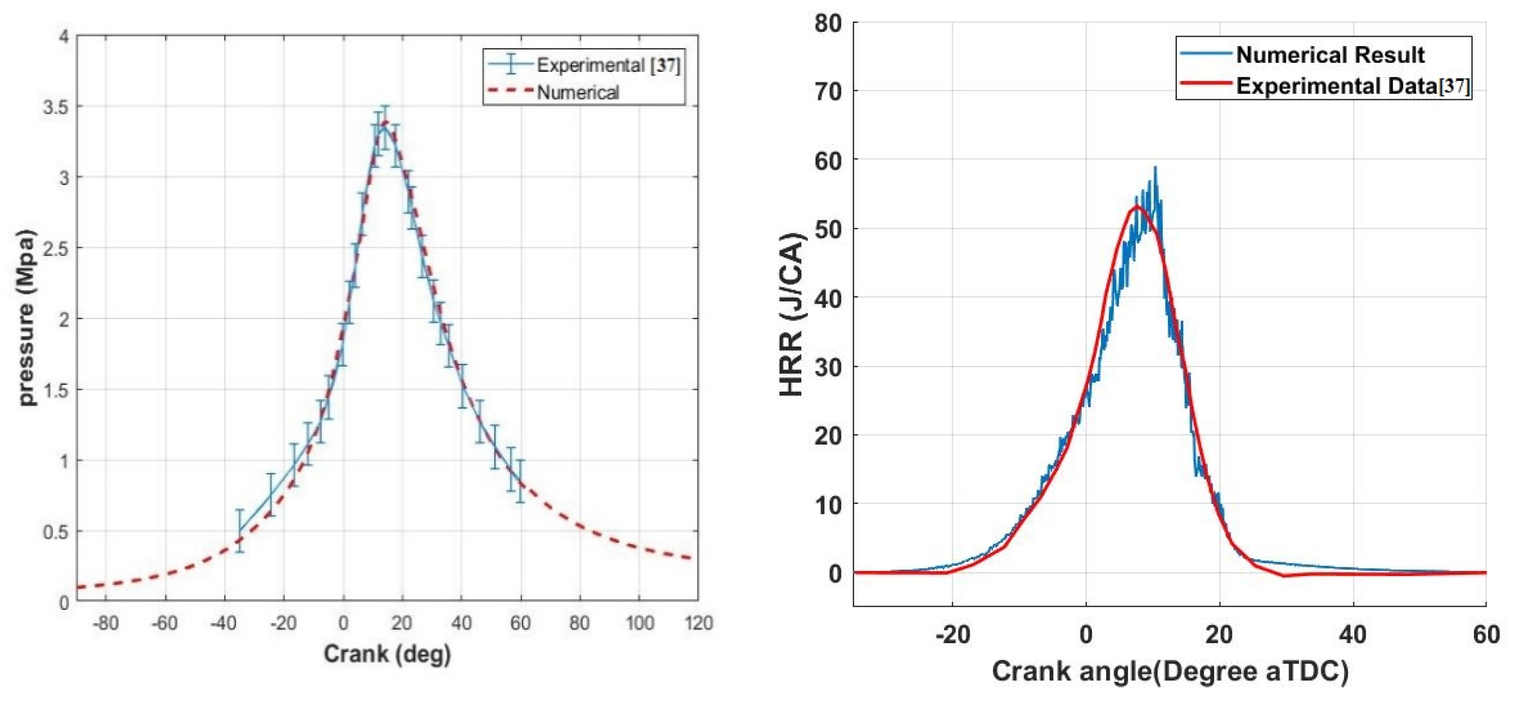
2.3. Numerical Model Validation

The simulation is implemented considering the engine operating at a low load (1500 rpm) with 0.55 bar of initial pressure and an initial temperature of 340 K (IVC). In this study, the boundary conditions of a constant pressure of 14 bar were applied for hydrogen fuel injection, so that for 50% hydrogen, the duration of fuel injection was about 20 CA. The instrumentation apparatus of the test setup is explained in Table 5. The simulation and experimental results presented [37] in the reference are compared to confirm the numerical results obtained from the CFD code of CONVERGE software. Figure 2 demonstrates the variation of pressure and heat release rate (HRR) with the crank angle for Gasoline PFI for a low load. The trends of simulation are similar to that of the experiment. For almost all points, the difference between the simulation and experimental pressure is less than 1.5 bar, and this difference is less than 1% for the maximum pressure point. As mentioned in reference [39], LFS (laminar flame speeds) data can be used to verify the results of hydrogen combustion. Validation has been done for 100% hydrogen and an equivalence ratio of 1 at WOT. As can be seen in Table 6, the simulation shows an acceptable accuracy in predicting the combustion details.

3. Results and Discussion

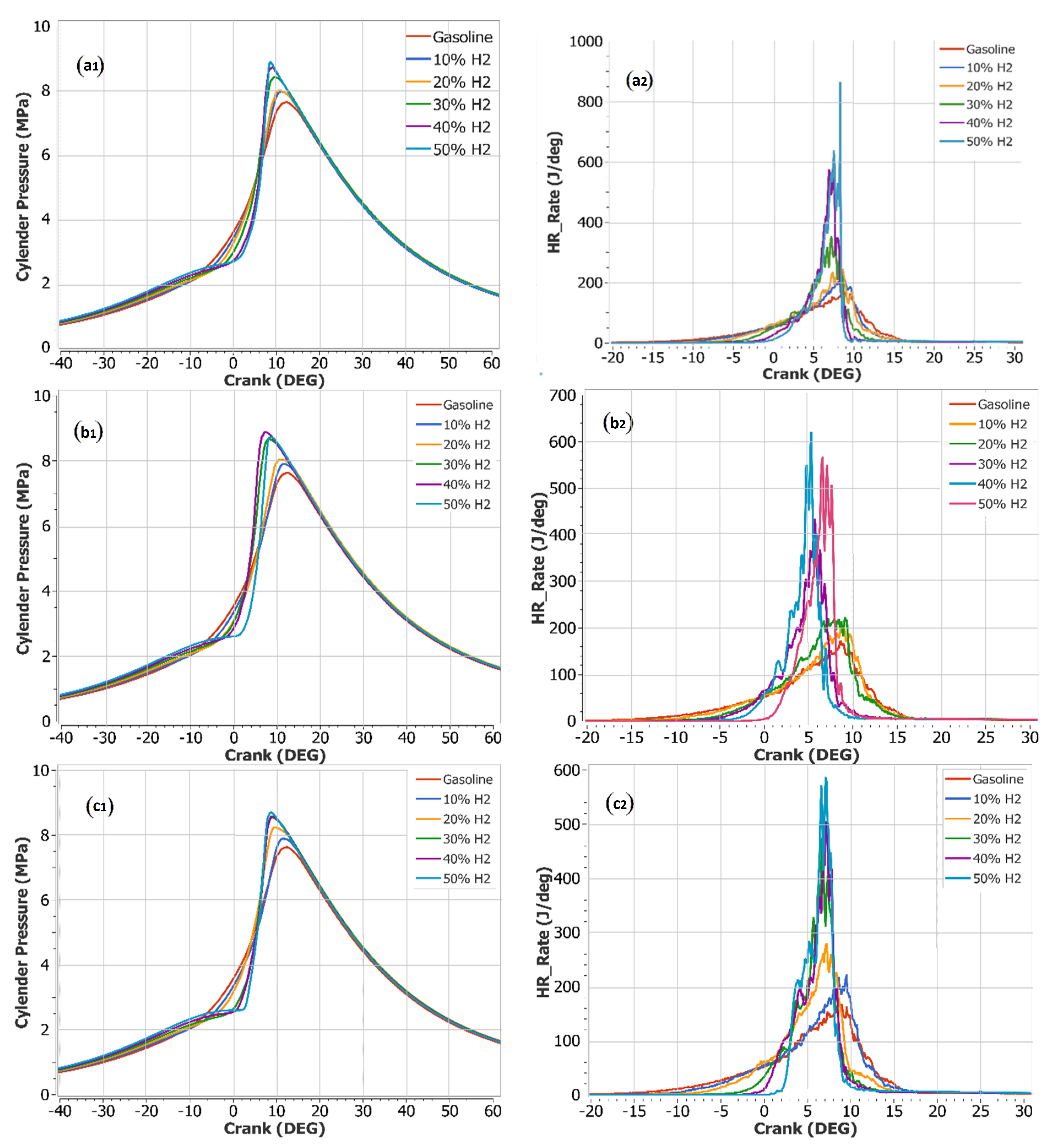
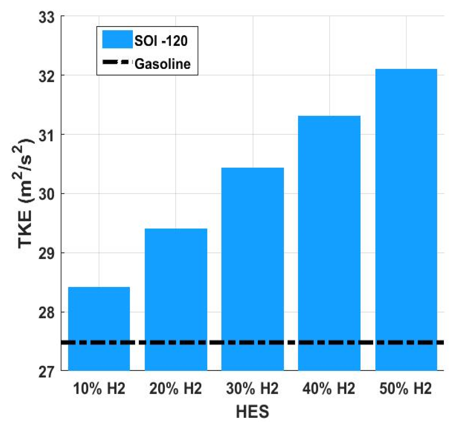
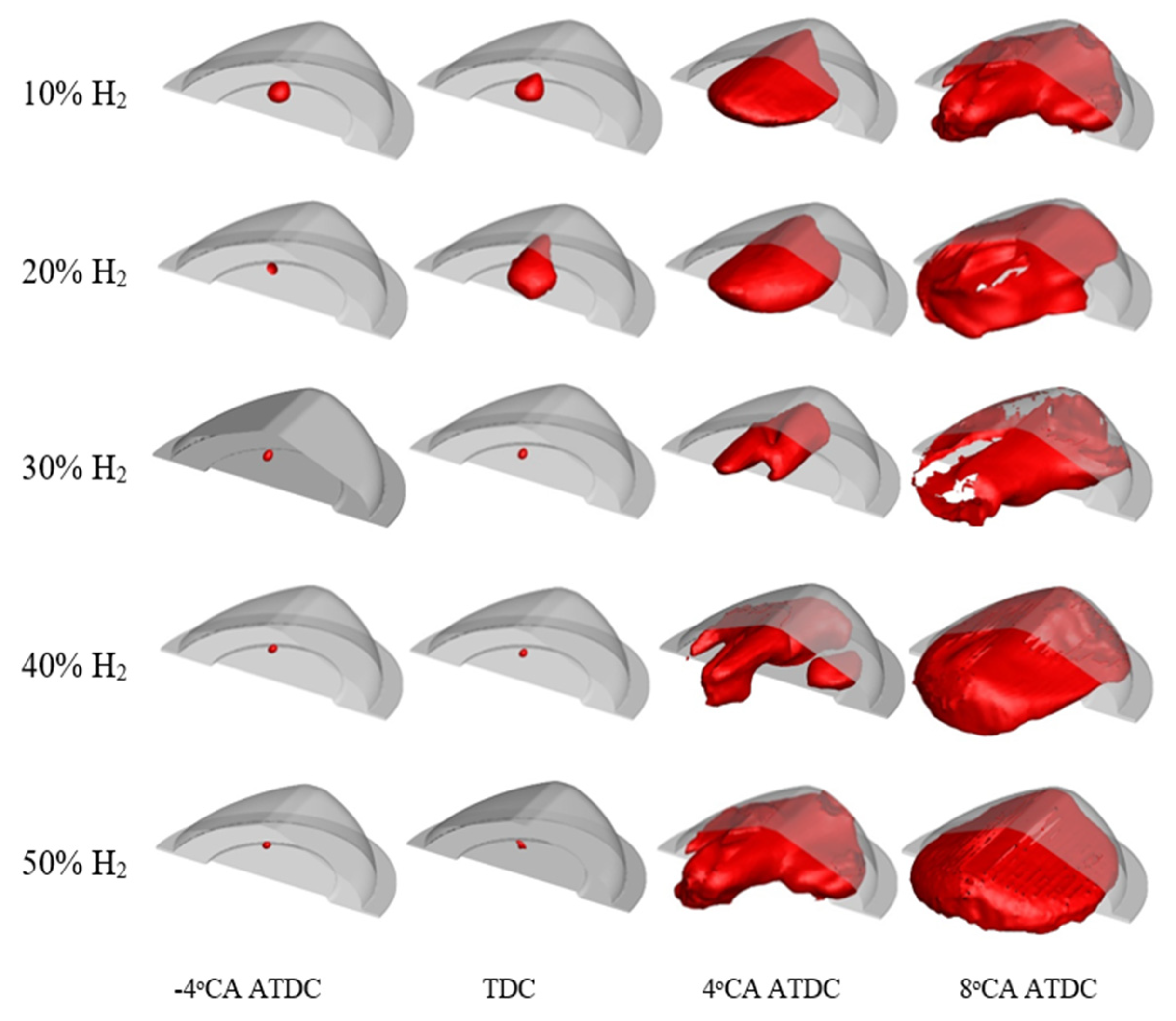
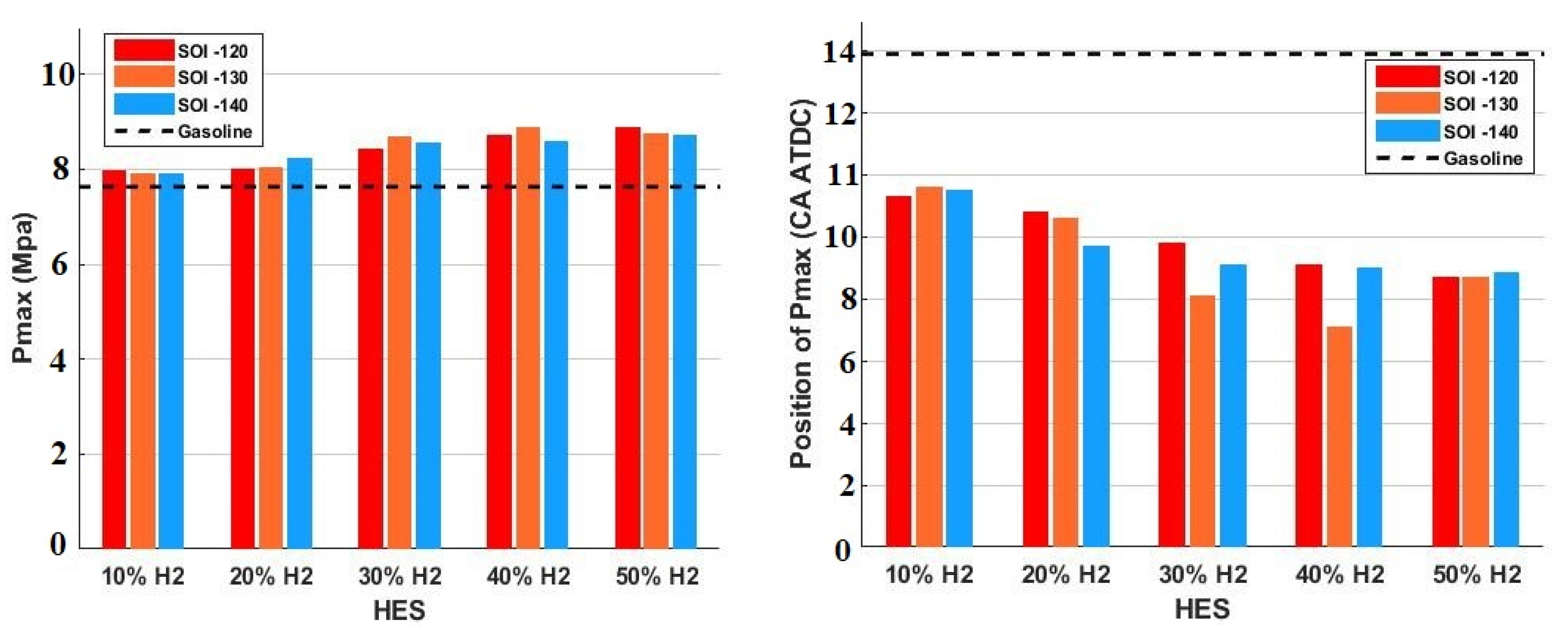
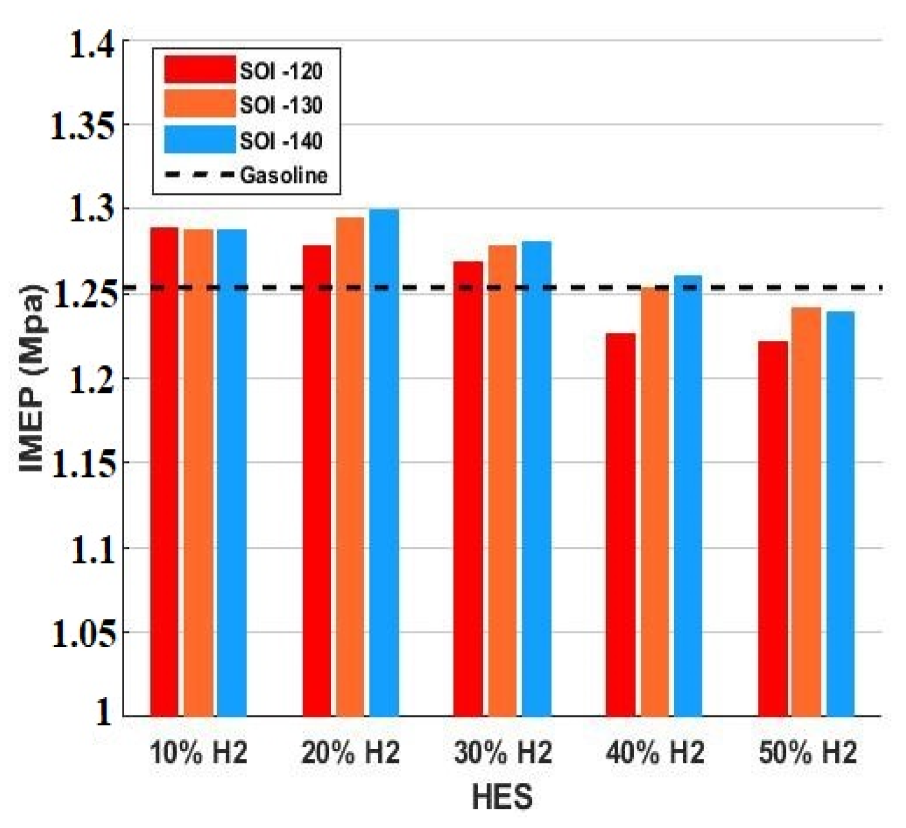
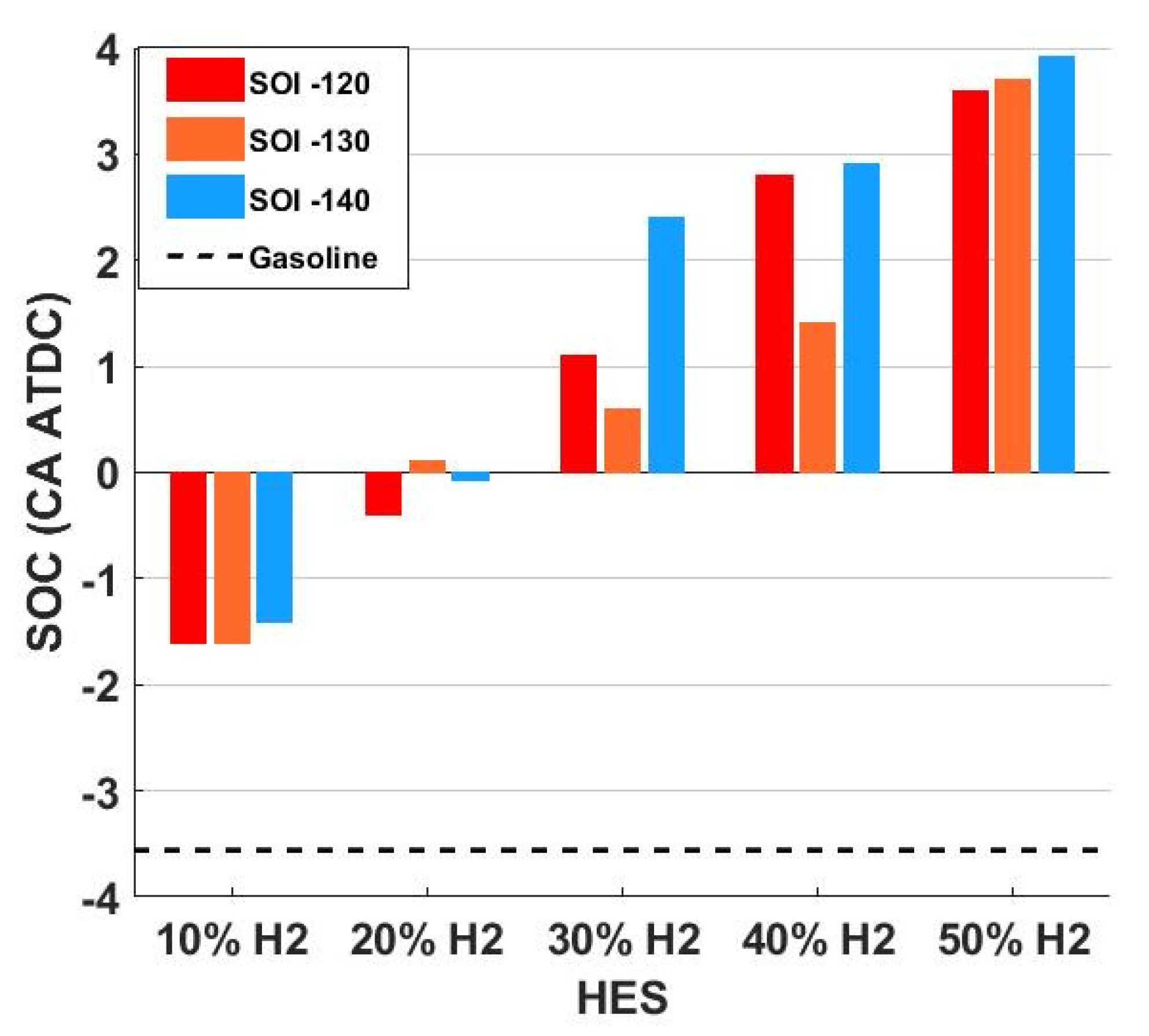
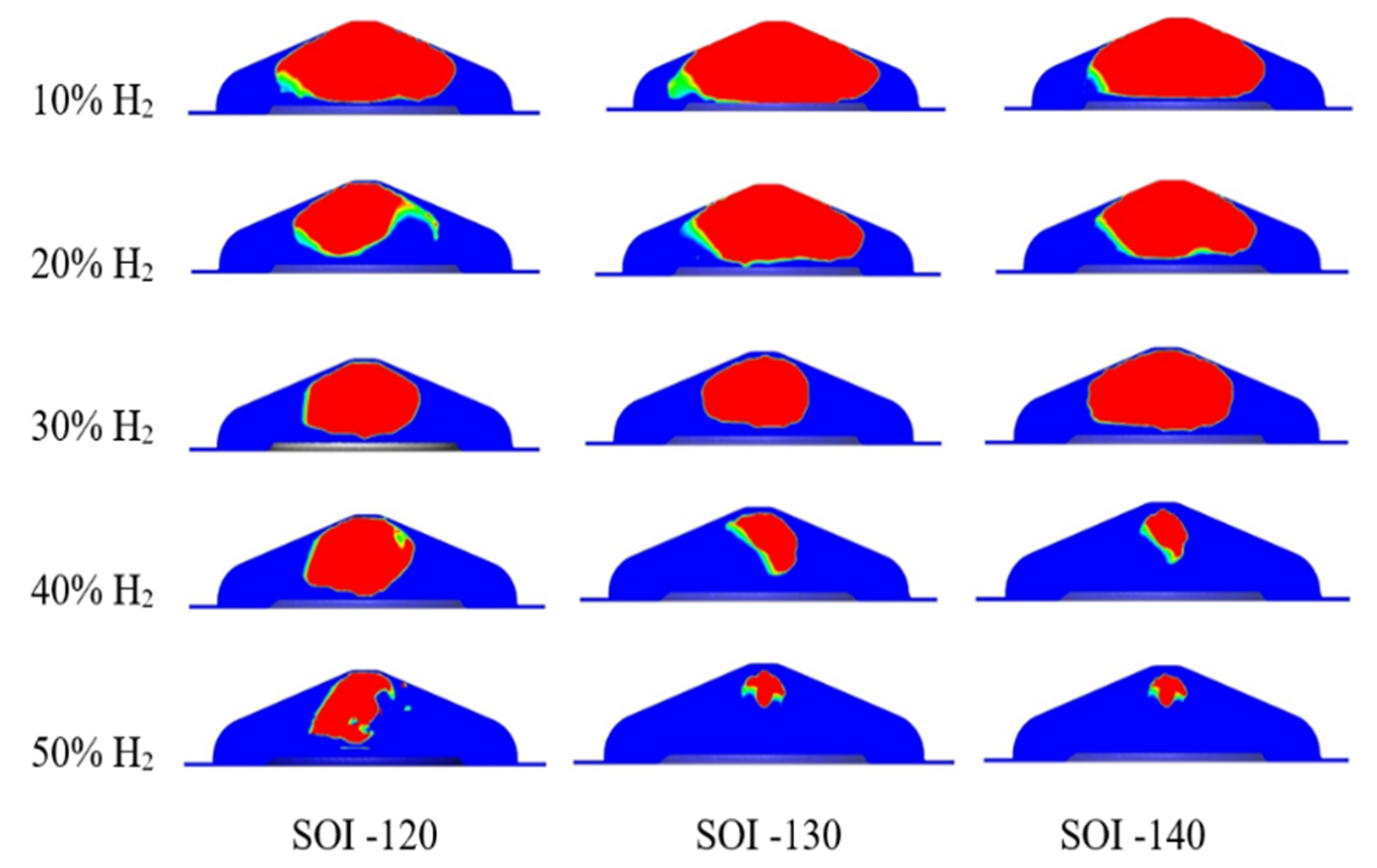
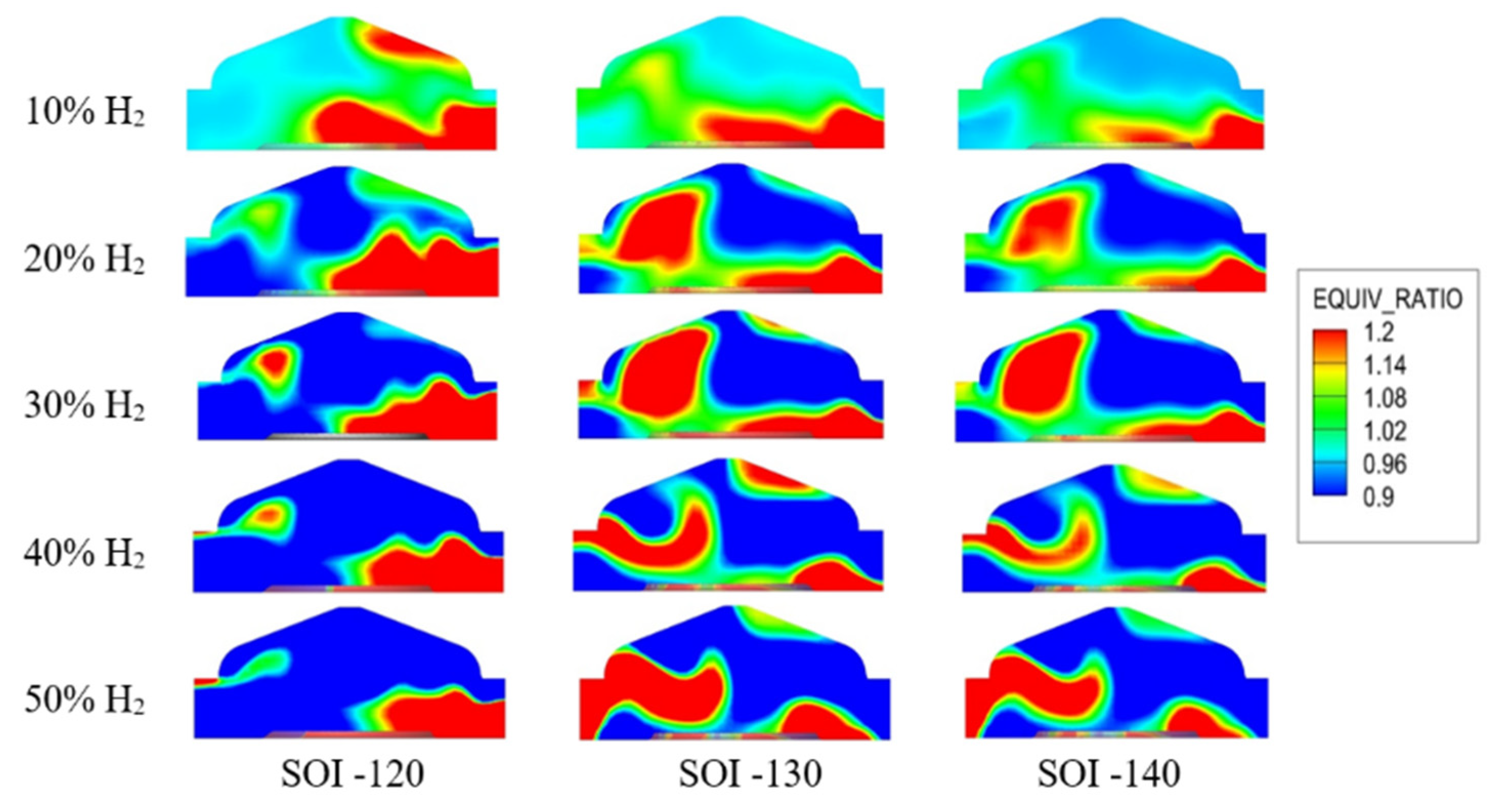
3.1. Influences of Direct Injection of Hydrogen on Combustion

Figure 3 explains the effects of the direct hydrogen injection timing and HES on the cylinder pressure at full load. Both maximum pressure and combustion rate increase with increasing hydrogen. Two main reasons are given to explain this observation. The first one, since hydrogen has a higher flame propagation speed compared to gasoline, the combustion process behaves in a constant volume mode leading to increased maximum pressure. Second, hydrogen has a wider combustion limit that makes combustion more complete.
Since the hydrogen is sprayed directly into the cylinder at high pressure, the hydrogen jet causes a better mixture which increases the turbulency. Therefore, fuel distribution in the mixture is higher and the combustion process is more efficient. As illustrated in Figure 4 with the addition of hydrogen, the amount of turbulent kinetic energy (TKE) increases, leading to faster and more complete combustion. This reduces the emissions and turns the combustion towards a constant volume process offering improved engine cycle efficiency.
In order to reach the maximum output torque, the ignition timing in all cases is set in such a way that CA50 is in the range of 7–9 CA aTDC. Therefore, with the addition of hydrogen, the ignition time is delayed due to the higher combustion speed of hydrogen. As a result, for 10% and 20%, the hydrogen combustion rate is observed to be higher in the range of −4 CA aTDC to TDC. However, as can be seen in Figure 5, with the addition of hydrogen, the combustion rate has increased from TDC to 4 CA aTDC. As can be seen in Figure 5, by adding hydrogen, the speed of combustion has increased significantly. The main reason for this observation is the higher combustion speed of hydrogen compared to gasoline. A higher combustion speed causes a constant volume combustion process, which results in higher maximum pressure and improves thermal efficiency.
Figure 6 illustrates the maximum pressure and position of the maximum pressure to better illustrate the effect of the direct hydrogen injection timing and HES. Compared to gasoline, the maximum pressure of HES from 10% to 50% increases by an average of 3.8%, 6.1%, 12%, 14.4% and 15%, respectively, and the maximum pressure position advances by 27.9%, 34.8%, 43.4%, 47.2% and 45.1%, respectively. As shown in Figure 3 and Figure 6, the faster the combustion rate, the higher the maximum pressure. Figure 3 illustrates the influence of the hydrogen direct-injection timing and HES on HRR. As the percentage of hydrogen increases, the HRR becomes more concentrated and more shifted in advance compared to the gasoline mode.
Indicated mean effective pressure (IMEP) is employed as a factor for investigations on engine efficiency. Figure 7 describes the effect of the hydrogen direct-injection timing and HES on IMEP. Since engine IMEP is influenced by fuel-mixture homogeneity, there is better performance at SOI −140 CAD aTDC, where hydrogen has more time to create a better mixture in the engine. With the increase of HES up to 30%, IMEP is more than pure gasoline, but when increasing the HES to 40% and 50%, because of hydrogen’s low energy density, IMEP is reduced. The maximum amount of IMEP is related to the state of 20% HES [44,45].
In all studied cases, the ignition timing is adjusted so that the CA50 is almost the same. By adding hydrogen, as seen in Figure 5, the combustion speed increases. Therefore, for higher hydrogen percentages, the ignition time is retarded, and this issue, as can be seen in Figure 8, causes the start of combustion (SOC) to be retarded. For hydrogen percentages higher than 20%, the SOC is after the top dead center. Therefore, the IMEP decreases significantly for hydrogen percentages higher than 20%. Hydroxide is one of the most important parameters to understand and detect the SOC. As illustrated in Figure 9, in the TDC, with hydrogen addition, the OH decreased, which is a confirmation of the observations in Figure 8. The main reason for this issue is the retardation in the ignition timing to achieve the same CA50 for different cases.

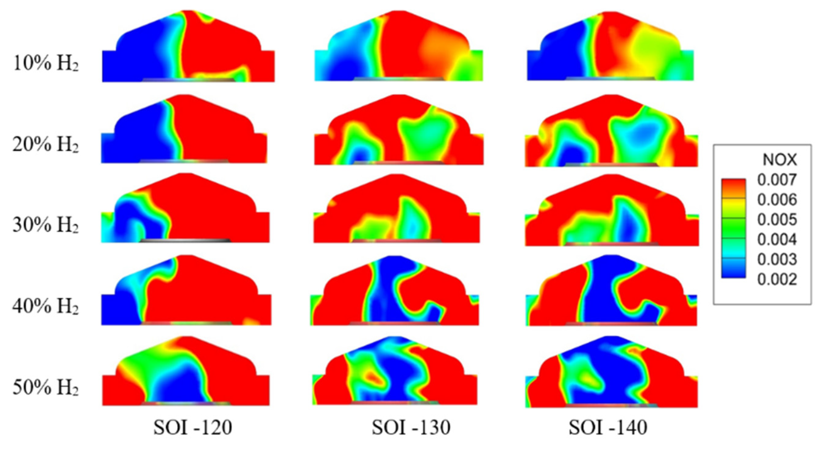
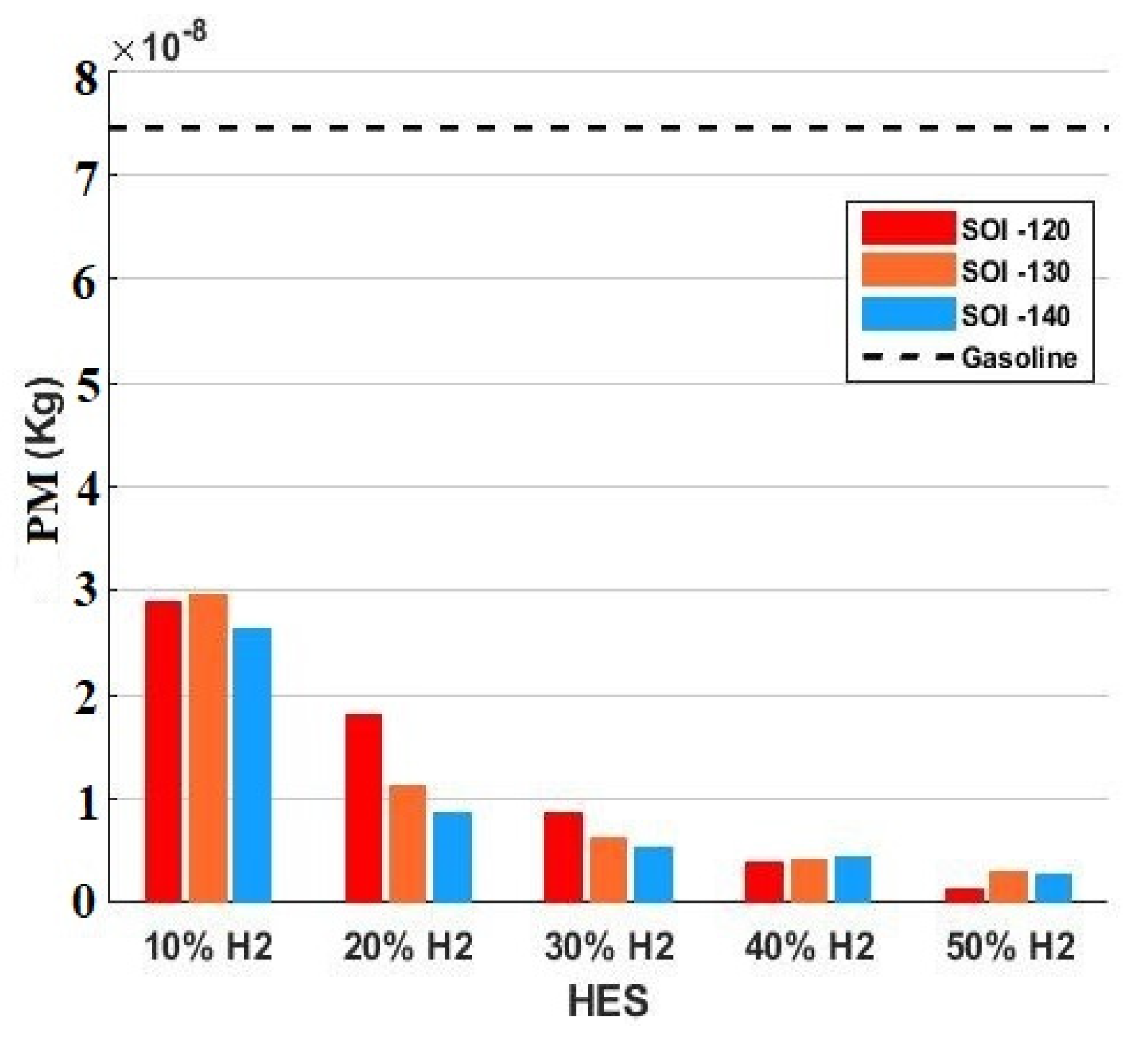
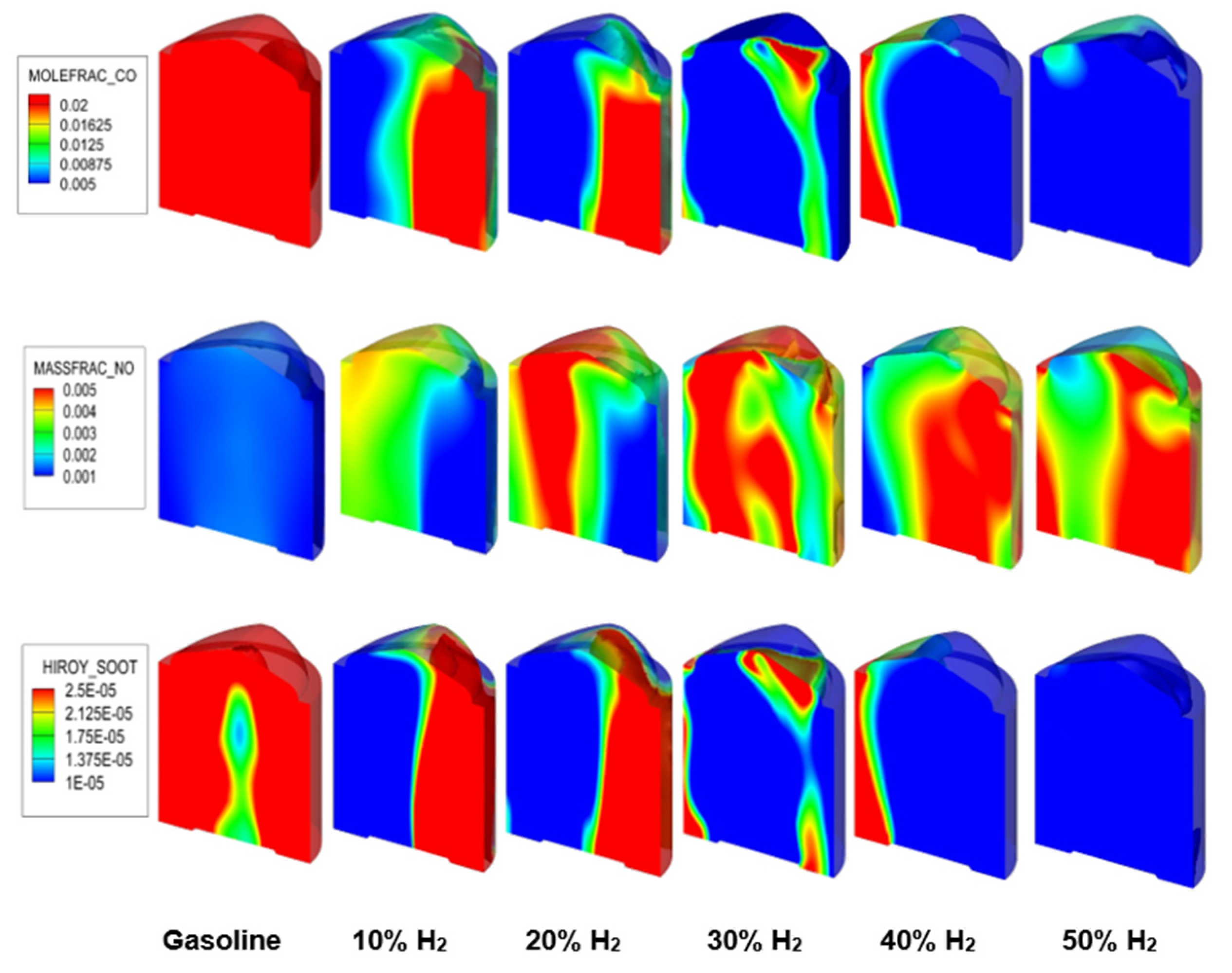
3.2. Influences of Hydrogen Direct Injection on Emissions

Figure 10 indicates the effect of the direct hydrogen injection timing and HES on NOX emissions. NOx emission behaves similarly to pressure and HRR. In this study, since the equivalence ratio is 1 and is considered uniform for all cases, the most important factor affecting NOX emission is temperature. The hydrogen addition clearly raises the temperature inside the cylinder, so the NOX also increases with increasing hydrogen. NOX emissions for various HES from 10% to 50% increase by an average of 73.2%, 126.2%, 172.4%, 191.8% and 198.3%, respectively.
As shown in Figure 10, at the same HES, the SOI of −120 CAD aTDC has the highest NOX emission. The main reason is that in this mode there is less time to create a homogeneous mixture, so some areas have a higher concentration of hydrogen than other areas, so the combustion temperature in these areas is higher than in other areas and more NOX is produced. In order to better understand this issue, the contours of the equivalence ratio and NOX are illustrated in Figure 11 and Figure 12. Figure 11 shows that in the case of SOI −120 CAD aTDC, due to retarded injection, there was less opportunity for homogeneous distribution of hydrogen, and therefore, most of the hydrogen was concentrated in only one area with high condensation. However, for SOI −130 and −140 CAD aTDC, due to more time to create a homogeneous mixture of hydrogen and air, the concentration of hydrogen in one area is reduced and different areas containing hydrogen are observed. As can be seen in Figure 12, in the areas where the concentration of hydrogen was higher, owing to the higher temperature of hydrogen combustion, more NOX emission is observed, and as the distribution of hydrogen becomes more homogeneous, NOX emission reduced, so for SOI −120 CAD aTDC the most NOX emission has been observed. The more homogeneous distribution of hydrogen has an effect on other pollutants such as CO and PM and has led to a further reduction in these pollutants, which will be discussed further.
Figure 13 shows the effect of the direct hydrogen injection timing and HES on CO emissions. Since hydrogen can make combustion more complete, CO emission is significantly reduced. Compared to gasoline, CO emissions for HES from 10% to 50% decrease by an average of 37.9%, 63.6%, 76.8%, 83.3% and 90.9%, respectively.
Figure 14 presents the effect of the hydrogen direct-injection timing and HES on PM emissions. Since hydrogen combustion is more complete, it reduces the distance of wall quenching resulting in reduced PM emissions. PM emissions for HES from 10% to 50% decrease by an average of 62.1%, 83.1%, 90.9%, 94.4% and 96.9%, respectively, compared to gasoline. At the SOI of −140 CAD aTDC, due to the longer time for more complete mixing, the homogeneous mixture is composed of hydrogen and more complete combustion takes place, so PM emissions show a greater reduction than in other cases.
The contour of the changes for CO, NOX and PM emissions with an increase in HES at EVO and SOI −120 aTDC are shown in Figure 15. As can be seen, with an increase in the percentage of hydrogen, CO and PM emissions decreased, which indicates more complete and clean combustion, but the NOX increased due to the higher combustion temperature of hydrogen.

4. Conclusions

A numerical study was conducted to investigate the effect of direct-injected hydrogen in a port-fueled gasoline SI engine. The influence of hydrogen injection-timing variation and HES on combustion and emissions characteristics were evaluated. In general, direct injection of hydrogen enhanced IMEP and sped up the combustion process along with engine efficiency improvement. For HES 20%, IMEP increased by 3.52% compared to pure gasoline PFI. Compared to gasoline PFI direct injection of hydrogen for HES 10, 20, 30, 40 and 50%, CO emissions reduced by 37.9%, 63.6%, 76.8%, 83.3% and 91%, respectively. In the same manner, for HES 10% to 50%, PM emissions reduced by 62.1%, 83.1%, 90.9%, 94.4% and 96.9%, respectively. Hydrogen direct injection increased the combustion average temperature as well which led to a higher concentration of NOX emissions, especially in the case with SOI −120 CAD aTDC due to a more heterogeneous mixture than in the other cases. In contrast, NOX emissions for the case with SOI −140 CAD aTDC were lower than the other cases due to the more homogeneous mixture wherein NOX reduced by an average of 15.8%, 14.4%, 2.4%, 2.8% and 21.2%, for HES from 10% to 50%, respectively, compared to SOI −120 CAD aTDC.

Author Contributions

The authors confirm contribution to the paper as follows: Study conception and design, A.G. and A.M.A.; Simulation and data collection, M.A.; Analysis and interpretation of results: A.G. and A.M.A.; Draft manuscript preparation: M.A. and A.G.; Verification of the methods: A.M.A., M.M., J.K.; Supervision and investigation of findings: M.M., J.K., A.P. and T.M. All authors have read and agreed to the published version of the manuscript.

Funding

This research received no external funding.

Data Availability Statement

This study did not report any data.

Conflicts of Interest

The authors declare no conflict of interest.

Abbreviations

aTDCAfter Top Dead Center
bTDCBefore Top Dead Center
CADCrank angle degree
DIDirect injection
COCarbon monoxide
CO2Carbon dioxide
COVCoefficient of variation
EVOExhaust valve open
EVCExhaust valve close
HESHydrogen energy share
HRRHeat release rate
IMEPIndicated mean effective pressure
IVOIntake valve open
IVCIntake valve close
ICEInternal combustion engine
TKETurbulent kinetic energy
PFIPort fuel injection
PMParticle Matter
RIRinging intensity
SISpark Ignition
SOIStart of injection
SOCStart of combustion

References

  1. Yu, S.-T.; Chang, S.-C.; Jorgenson, P.; Park, S.-J.; Lai, M.-C. Basic equations of chemically reactive flows for computational fluid dynamics. In Proceedings of the 36th AIAA Aerospace Sciences Meeting and Exhibit, Reno, NV, USA, 12–15 January 1998. [Google Scholar] [CrossRef]
  2. Andwari, A.M.; Pesiridis, A.; Esfahanian, V.; Said, M.F.M. Combustion and Emission Enhancement of a Spark Ignition Two-Stroke Cycle Engine Utilizing Internal and External Exhaust Gas Recirculation Approach at Low-Load Operation. Energies 2019, 12, 609. [Google Scholar] [CrossRef] [Green Version]
  3. Andwari, A.M.; Said, M.F.M.; Aziz, A.A.; Esfahanian, V.; Salavati-Zadeh, A.; Idris, M.A.; Perang, M.R.M.; Jamil, H.M. Design, Modeling and Simulation of a High-Pressure Gasoline Direct Injection (GDI) Pump for Small Engine Applications. J. Mech. Eng. 2018, 1, 107–120. [Google Scholar]
  4. Andwari, A.M.; Aziz, A.A.; Said, M.F.M.; Latiff, Z.A.; Ghanaati, A. Influence of Hot Burned Gas Utilization on The Exhaust Emission Characteristics of A Controlled Auto-Ignition Two-Stroke Cycle Engine. Int. J. Automot. Mech. Eng. 2015, 11, 2396–2404. [Google Scholar] [CrossRef]
  5. Tartakovsky, L.; Sheintuch, M. Fuel reforming in internal combustion engines. Prog. Energy Combust. Sci. 2018, 67, 88–114. [Google Scholar] [CrossRef]
  6. Kamil, M.; Rahman, M.M. Performance prediction of spark-ignition engine running on gasoline-hydrogen and methane-hydrogen blends. Appl. Energy 2015, 158, 556–567. [Google Scholar] [CrossRef]
  7. Yu, X.; Li, D.; Yang, S.; Sun, P.; Guo, Z.; Yang, H.; Li, Y.; Wang, T. ScienceDirect Effects of hydrogen direct injection on combustion and emission characteristics of a hydrogen/Acetone-Butanol-Ethanol dual-fuel spark ignition engine under lean-burn conditions. Int. J. Hydrogen Energy 2020, 45, 34193–34203. [Google Scholar] [CrossRef]
  8. Niu, R.; Yu, X.; Du, Y.; Xie, H.; Wu, H.; Sun, Y. Effect of hydrogen proportion on lean burn performance of a dual fuel SI engine using hydrogen direct-injection. Fuel 2016, 186, 792–799. [Google Scholar] [CrossRef]
  9. Ji, C.; Wang, S.; Zhang, B.; Liu, X. Emissions performance of a hybrid hydrogen–gasoline engine-powered passenger car under the New European Driving Cycle. Fuel 2013, 106, 873–875. [Google Scholar] [CrossRef]
  10. Saravanan, N.Ã.; Nagarajan, G. An experimental investigation of hydrogen-enriched air induction in a diesel engine system. Int. J. Hydrogen Energy 2008, 33, 1769–1775. [Google Scholar] [CrossRef]
  11. Soyhan, H.S.; Karabag, B. Emission characteristics of an hydrogen–CH4 fuelled spark ignition engine. Fuel 2015, 159, 298–307. [Google Scholar]
  12. Ceviz, M.A.; Sen, A.K. Engine performance, exhaust emissions, and cyclic variations in a lean-burn SI engine fueled by gasoline e hydrogen blends. Appl. Therm. Eng. 2012, 36, 314–324. [Google Scholar] [CrossRef]
  13. Yu, X.; Du, Y.; Sun, P.; Liu, L.; Wu, H.; Zuo, X. Effects of hydrogen direct injection strategy on characteristics of lean-burn hydrogen–gasoline engines. Fuel 2017, 208, 602–611. [Google Scholar] [CrossRef]
  14. Wang, S.; Ji, C. Cyclic variation in a hydrogen-enriched spark-ignition gasoline engine under various operating conditions. Int. J. Hydrogen Energy 2011, 37, 1112–1119. [Google Scholar] [CrossRef]
  15. Welch, A.; Mumford, D.; Munshi, S.; Holbery, J.; Boyer, B.; Younkins, M.; Jung, H. Challenges in Developing Hydrogen Direct Injection Technology for Internal Combustion Engines; SAE International: Warrendale, PA, USA, 2018. [Google Scholar] [CrossRef]
  16. Kahraman, E.; Ozcanh, S.C.; Ozerdem, B. An experimental study on performance and emission characteristics of a hydrogen fuelled spark ignition engine. Int. J. Hydrogen Energy 2007, 32, 2066–2072. [Google Scholar] [CrossRef] [Green Version]
  17. Verhelst, S.; Wallner, T. Hydrogen-fueled internal combustion engines. Prog. Energy Combust. Sci. 2009, 35, 490–527. [Google Scholar] [CrossRef] [Green Version]
  18. Ji, C.; Wang, S.; Zhang, B. Effect of spark timing on the performance of a hybrid hydrogen–gasoline engine at lean conditions. Int. J. Hydrogen Energy 2010, 35, 2203–2212. [Google Scholar] [CrossRef]
  19. Ji, C.; Wang, S. Experimental study on combustion and emissions performance of a hybrid hydrogen–gasoline engine at lean burn limits. Int. J. Hydrogen Energy 2010, 35, 1453–1462. [Google Scholar] [CrossRef]
  20. Ji, C.; Cong, X.; Wang, S.; Shi, L.; Su, T.; Wang, D. Performance of a hydrogen-blended gasoline direct injection engine under various second gasoline direct injection timings. Energy Convers. Manag. 2018, 171, 1704–1711. [Google Scholar] [CrossRef]
  21. Hao, L.; Xu, X.; Guo, X.; Ji, C.; Wang, X.; Tan, J.; Ge, Y. Investigation of cold-start emission control strategy for a bi-fuel hydrogen/gasoline engine. Int. J. Hydrogen Energy 2016, 41, 18273–18281. [Google Scholar] [CrossRef]
  22. Wang, S.; Ji, C.; Zhang, M.; Zhang, B. Reducing the idle speed of a spark-ignited gasoline engine with hydrogen addition. Int. J. Hydrogen Energy 2010, 35, 10580–10588. [Google Scholar] [CrossRef]
  23. Ji, C.; Wang, S.; Zhang, B. Combustion and emissions characteristics of a hybrid hydrogen e gasoline engine under various loads and lean conditions. Int. J. Hydrogen Energy 2010, 35, 5714–5722. [Google Scholar] [CrossRef]
  24. He, F.; Li, S.; Yu, X.; Du, Y.; Zuo, X. Comparison study and synthetic evaluation of combined injection in a spark ignition engine with hydrogen-blended at lean burn condition. Energy 2018, 157, 1053–1062. [Google Scholar] [CrossRef]
  25. Al-Baghdadi, M.A.-R.S. A study on the hydrogen-ethyl alcohol dual fuel spark ignition engine. Energy Convers. Manag. 2002, 43, 199–204. [Google Scholar] [CrossRef]
  26. Ji, C.; Shi, C.; Wang, S.; Yang, J.; Su, T.; Wang, D. Effect of dual-spark plug arrangements on ignition Effect of dual-spark plug arrangements on ignition and combustion processes of a gasoline rotary engine with hydrogen direct-injection enrichment. Energy Convers Manag. 2018, 181, 372–381. [Google Scholar] [CrossRef]
  27. Wu, H.; Yu, X.; Du, Y.; Ji, X.; Niu, R.; Sun, Y.; Gu, J. Study on cold start characteristics of dual fuel SI engine with hydrogen direct-injection. Appl. Therm. Eng. 2016, 100, 829–839. [Google Scholar] [CrossRef]
  28. Li, G.; Yu, X.; Jin, Z.; Shang, Z.; Li, D.; Li, Y.; Zhao, Z. Study on effects of split injection proportion on hydrogen mixture distribution, combustion and emissions of a gasoline/hydrogen SI engine with split hydrogen direct injection under lean burn condition. Fuel 2020, 270, 117488. [Google Scholar] [CrossRef]
  29. Li, G.; Yu, X.; Shi, W.; Yao, C.; Wang, S.; Shen, Q. Effects of split injection proportion and the second injection timings on the combustion and emissions of a dual fuel SI engine with split hydrogen direct injection. Int. J. Hydrog. Energy 2019, 44, 11194–11204. [Google Scholar] [CrossRef]
  30. Du, Y.; Yu, X.; Liu, L.; Li, R. Effect of addition of hydrogen and exhaust gas recirculation on characteristics of hydrogen gasoline engine. Int. J. Hydrogen Energy 2017, 42, 8288–8298. [Google Scholar] [CrossRef]
  31. Sun, Y.; Yu, X.; Jiang, L. Effects of direct hydrogen injection on particle number emissions from a lean burn gasoline engine. Int. J. Hydrogen Energy 2016, 41, 18631–18640. [Google Scholar] [CrossRef]
  32. Du, Y.; Yu, X.; Wang, J.; Wu, H. Research on combustion and emission characteristics of a lean burn gasoline engine with hydrogen direct-injection. Int. J. Hydrogen Energy 2015, 41, 3240–3248. [Google Scholar] [CrossRef]
  33. Yu, X.; Wu, H.; Du, Y.; Tang, Y.; Liu, L.; Niu, R. Research on cycle-by-cycle variations of an SI engine with hydrogen direct injection under lean burn conditions. Appl. Therm. Eng. 2016, 109, 569–581. [Google Scholar] [CrossRef]
  34. Sun, Y.; Yu, X.; Dong, W.; Tang, Y. Effects of hydrogen direct injection on engine stability and optimization of control parameters for a combined injection engine. Int. J. Hydrogen Energy 2018, 43, 6723–6733. [Google Scholar] [CrossRef]
  35. Shi, W.; Yu, X.; Zhang, H.; Li, H. Effect of spark timing on combustion and emissions of a hydrogen direct injection stratified gasoline engine. Int. J. Hydrogen Energy 2017, 42, 5619–5626. [Google Scholar] [CrossRef]
  36. Pamminger, M.; Sevik, J.; Wooldridge, S.; Boyer, B. Performance, efficiency and emissions evaluation of gasoline port-fuel injection, natural gas direct injection and blended operation. In Proceedings of the ASME 2016 Internal Combustion Engine Division Fall Technical Conference, Greenville, SC, USA, 9–12 October 2016. ICEF2016-9370. [Google Scholar] [CrossRef]
  37. Liu, Y.-D.; Jia, M.; Xie, M.-Z.; Pang, B. Enhancement on a skeletal kinetic model for primary reference fuel oxidation by using a semidecoupling methodology. Energy Fuels 2012, 26, 7069–7083. [Google Scholar] [CrossRef]
  38. Aghahasani, M.; Gharehghani, A.; Andwari, A.M.; Mikulski, M.; Könnö, J. Effect of natural gas direct injection (NGDI) on the performance and knock behavior of an SI engine. Energy Convers Manag. 2022, 269, 116145. [Google Scholar] [CrossRef]
  39. Han, W.; Dai, P.; Gou, X.; Chen, Z. A review of laminar flame speeds of hydrogen and syngas measured from propagating spherical flames. Appl. Energy Combust. Sci. 2020, 1–4, 100008. [Google Scholar] [CrossRef]
  40. Huang, Z.; Zhang, Y.; Zeng, K.; Liu, B.; Wang, Q. Measurements of laminar burning velocities for natural gas–hydrogen–air mixtures. Combust. Flame 2006, 146, 302–311. [Google Scholar] [CrossRef]
  41. Tse, S.D.; Zhu, D.L.; Law, C.K. Morphology and burning rates of expanding spherical flames in h2/o2/inert mixtures up to 60 atmospheres. Proc. Combust. Inst. 2000, 28, 1793–1800. [Google Scholar] [CrossRef] [Green Version]
  42. Lamoureux, N.; Djeba, N.; Paillard, C. Laminar flame velocity determination for H2–air–He–CO2 mixtures using the spherical bomb method. Exp. Therm. Fluid Sci. 2003, 27, 385–393. [Google Scholar] [CrossRef]
  43. Gharehghani, A.; Ghasemi, K.; Siavashi, M.; Mehranfar, S. Applications of porous materials in combustion systems: A comprehensive and state-of-the-art review. Fuel 2021, 304, 121411. [Google Scholar] [CrossRef]
  44. Kakoee, A.; Gharehghani, A.; Mostafaei, M. Development of a reduced chemical kinetic mechanism for biodiesel/natural gas mixture. Fuel 2022, 312, 122920. [Google Scholar] [CrossRef]
  45. Moradi, J.; Gharehghani, A.; Aghahasani, M. Application of machine learning to optimize the combustion characteristics of RCCI engine over wide load range. Fuel 2022, 324, 124494. [Google Scholar] [CrossRef]
Figure 1. Geometry of cylinder used in computational fluid dynamic (CFD) simulation. Reproduced with permission from Aghahasani, M., etc., Energy Convers Manag.; published by Elsevier, 2022 [38].
Processes 10 02249 g001
Figure 2. Validation of model by cylinder pressure and Heat Release Rate (HRR) for 100% gasoline port fuel injection. Reproduced with permission from Pamminger, M., etc., Proceedings of the ASME 2016 Internal Combustion Engine Division Fall Technical Conference; published by ASME, 2016 [37].
Processes 10 02249 g002
Figure 3. Effects of direct hydrogen injection timing and hydrogen energy share (HES) on the in-cylinder pressure and HRR for SOI (a1,a2) −120 crank angle degree after top dead center (CAD aTDC) (b1,b2) −130 CAD aTDC (c1,c2) −140 CAD aTDC.
Processes 10 02249 g003
Figure 4. Effects of HES on turbulent kinetic energy (TKE) for SOI −120 CA aTDC.
Processes 10 02249 g004
Figure 5. Flame propagation contours for different HES. Reproduced with permission from Aghahasani, M., etc., Energy Convers Manag.; published by Elsevier, 2022 [43].
Processes 10 02249 g005
Figure 6. Effects of hydrogen direct-injection timing and HES on PMAX and position of PMAX.
Processes 10 02249 g006
Figure 7. Influences of hydrogen direct-injection timing and HES on indicated mean effective pressure (IMEP).
Processes 10 02249 g007
Figure 8. Start of combustion (SOC) for different case studies.
Processes 10 02249 g008
Figure 9. Contours of OH for different case studies at Top Dead Center (TDC).
Processes 10 02249 g009
Figure 10. Influences of hydrogen direct-injection timing and HES on NOX emissions.
Processes 10 02249 g010
Figure 11. Contours of equivalence ratio for different case studies at −40 CAD aTDC.
Processes 10 02249 g011
Figure 12. Contours of NOX emissions for different case studies at 40 CAD aTDC.
Processes 10 02249 g012
Figure 13. Effects of direct hydrogen injection timing and HES on the CO emissions.
Processes 10 02249 g013
Figure 14. Effects of direct hydrogen injection timing and HES on particulate matter (PM) emissions.
Processes 10 02249 g014
Figure 15. Effects of HES on CO, NOX and PM emissions for start of injection (SOI) −120 CAD aTDC at exhaust valve open (EVO).
Processes 10 02249 g015
Table 1. Fuel properties. Reproduced with permission from Li, G., etc., Int. J. Hydrog. Energy; published by Elsevier, 2019 [27,28].
Fuel PropertiesHydrogen (H2)Gasoline
Diffusion coefficient (cm2/s)0.610.16
Lower heating value (MJ/kg)12044
Laminar burning velocity (cm/s)
(298 K, excess air ratio = 1, 0.1 MPa
20741.5
Flammability limit (excess air ratio)0.14–10.080.6–2.4
Adiabatic flame temperature (K)
(Excess air ratio = 1)
23182148
Table 2. Engine specifications and operational conditions. Reproduced with permission from Aghahasani, M., etc., Energy Convers Manag.; published by Elsevier, 2022 [38].
ParametersSpecification
Displacement (cm3)626.4
Stroke (mm)100.6
Bore (mm)89.04
Compression Ratio (Geometric)10.5:1
Number of Intake and Exhaust Valve2/2
EVO/EVC (CAD aTDC fired)150/−350
IVO/IVC (CAD aTDC fired)350/−140
Table 3. Sub-model group used in CFD simulation. Reproduced with permission from Li, G., etc., Int. J. Hydrog. Energy; published by Elsevier, 2019 [30,28].
Model of ParametersCharacteristics
Turbulence RNG k-Model
Wall heat transfer O’Rourke and Amsden Model
Combustion SAGE
Ignition Spark-energy Deposition Model
Table 4. Operational performance of engine. Reproduced with permission from Aghahasani, M., etc., Energy Convers Manag.; published by Elsevier, 2022 [38].
ParameterCharacteristics
Engine speed1500 rpm
Equivalence ratio1.0
Gasoline (E10) LHV(MJ/kg)42.02
Hydrogen (H2) LHV(MJ/kg)120
Inlet pressure1.06 bar
Table 5. Instrumentation apparatus for measurement. Reproduced with permission from Aghahasani, M., etc., Energy Convers Manag.; published by Elsevier, 2022 [38].
ApparatusProduction Type
Ignition timingMotec M800
Injection timing (SOI)Motec M800
Throttling RegulatorsParker Pilot
Fuel flow meterCoriolis fuel meter CMF010
Crank angle position encoderAVL 365X
In-cylinder pressure transducerAVL GU21C
Table 6. Validation of LFS against measured data for RCNG = 100%.
LFS Measured Data (cm/s)LFS Experimental (cm/s)Error
201198 [40]1.5%
201205 [41]1.9%
201197 [42]2%
Publisher’s Note: MDPI stays neutral with regard to jurisdictional claims in published maps and institutional affiliations.

