Abstract
3D auxetic structures, which present negative Poisson’s ratio in the uniaxial compression deformation, is an ideal artificial material for meta-implants because of its lightweight, good material property and suitable porosity for bone recovery compared with conventional meta-biomaterials. Selective laser melting (SLM) is commonly used to produce metallic 3D auxetic structures but limited by the melting temperature and reflect rate of the material, and micro assembled (MA) structures is an alternative manufacturing process. However, the influence of size effect in 3D auxetic structures and the difference of the constitutive model of 3D auxetic structure produced by SLM and MA have not been discussed. In tandem of this, the mechanical property comparison of 3D auxetic structures produced by SLM and MA is conducted and a structural surface layer model for 3D auxetic structures is proposed. The result indicated that both SLM and MA structure can achieve auxetic effect. It is found that the Poisson’s ratio of the SLM and MA structures decrease when increasing the size factor of the structure, and the negative Poisson’s ratio effect is more obvious when the Young’s modulus is relatively small. FE simulation result of Poisson’s ratio is closer to experimental result of MA structures due to complexity of 3D auxetic structures. This paper thus provides a relatively helpful constitutive model for the prediction of the mechanical behavior of 3D auxetic structure.
1. Introduction
Auxetic material and structure has been widely studied in modern industry [1]. In contrast with the conventional material and structure, the auxetic structure is contracted when compression force is applied in lateral direction because of the negative Poisson’s ratio effect. Lakes created a foam structure with negative Poisson’s ratio by conducting heat treatment to polyurethane foam, and successfully obtained a structure with the Poisson’s ratio of −0.7 [2]. Evans et al. discovered that negative Poisson’s ratio effect existed when porous Teflon structure was under compression stress [3], and a simplified microstructure model was established to explain this phenomenon. Later, Evans et al. named the material with microstructure of negative Poisson’s ratio as the “auxetic materials” [4].
In the field of the computational study of auxetic material, Wojciechowski was the first to introduce a constant thermodynamic tension Monte Carlo method to study a two-dimensional system of hard cyclic hexamers. He demonstrated the existence of a crystal-crystal phase transition in the system and proved that Poisson’s ratio of the densest phase can be negative [5]. Later, he provided a 2D lattice model of hexagonal molecules and proved that the Poisson’s ratio of an isotropic system can be equal to any negative value in the range between minus one and zero [6]. The simulation results were confirmed in Ref. [7] by using another simulation method. Kolpakov presented a model indicated that the Poisson coefficient of a macroscopic structure of periodic configuration can be less than zero under certain conditions [8]. Hoover et al. provided the earliest approach on dynamic analyses of macroscopic periodic cellular structures and the maximum negative Poisson’s ratio was obtained [9]. Pozniak et al. studied the size effects in auxetics for non-periodic structure [10]. For auxetic star structure, Bilski et al. proposed research on the elastic properties of 2D crystalline structures, and the phenomenon that Poisson’s ratio decreased with increasing pressure was revealed [11]. Deformations and damages in wood-based sandwich beams with three dimensional structures similar to the one studied in the present paper were recently investigated by Smardzewski, and the ability of energy absorption in multilayer panel was studied [12].
As for the auxeticity of other mechanism except the mechanical relations of beams in rigid bodies, Baughman et al. indicated that pairwise central forces are the main reason of the negative Poisson’s ratio for the (110) stretch [13]. Piglowski et al. studied the size polydispersity on auxetic properties of Yukawa crystals and the conclusion that the decrease of the Poisson’s ratio is caused by particle size polydispersity was carried out [14]. Narojczyk and Wojciechowski found that the Poisson’s ratio increased with increasing disorder at a certain number density of soft sphere systems [15]. Later, they proposed a study on the influence of inclusion particles’ size to the Poisson’s ratio of nanocomposites [16]. As one of the most common negative Poisson’s ratio structures, the concave structure achieves the negative Poisson’s ratio of the material by unfolding both sides of the unit cell. The concave structure was first transformed from the two-dimensional honeycomb structure. Almgren obtained the concave hexagonal structure by connecting rigid bars with hinges, and its isotropic elastic property in macro scale has been discovered [17]. Larsen et al. used numerical topology optimization to design a novel negative Poisson’s ratio structure composed of double-arrow unit cells which was fabricated by chemical vapor deposition [18]. Grima established a two-dimensional periodic star structure, and the conclusion that the negative Poisson’s ratio effect doesn’t exist in every kind of star structure has been made [19]. Shokri et al. proposed a 3D auxetic structure based on 2D structure. By comparing the FE simulation and experiment result, the influence of the pillar thickness of the unit cell to the mechanical property has been revealed [20]. Hengsbach et al. used direct laser writing to obtain 3D auxetic structure with complex shape [21]. Wang et al. presented a 3D negative Poisson’s ratio structure by applying interlocking assemble technic [22]. The influence of the length and angle between the vertical and oblique strut of each unit cell was discussed, and the negative Poisson’s ratio effect was quantified. Li et al. prepared an auxetic structure of Ti-6Al-4V using electron beam melting (EBM) and the influence of the Poisson’s ratio to structural mechanical property was discovered [23]. This previous research has provided the theoretical foundation for the application of the auxetic structure.
For complex 3D structure, most of the negative Poisson’s ratio structures were prepared by 3D printing, which was able to manufacture arbitrarily complex parts, shorten product development cycle, and improve material utilization. The disadvantages of this technic were the relatively high cost, low production efficiency and dependence on materials. In previous research, little attention has been paid to the influence of the pillar thickness of the unit cell to the Poisson’s ratio [22]. For this reasons, microforming and micro assembled 3D auxetic structure is carried out in this research, and the mechanical properties are compared with the structures made by SLM. The quasi-static compression test is conducted on both SLM and MA auxetic structure, and the stress-strain relationship obtained from the experiment is compared with the corresponding FE simulation result. The influence of pillar thickness of the unit cell is revealed and a structural-surface-layer (SSL) model is thus established.
2. Experiment
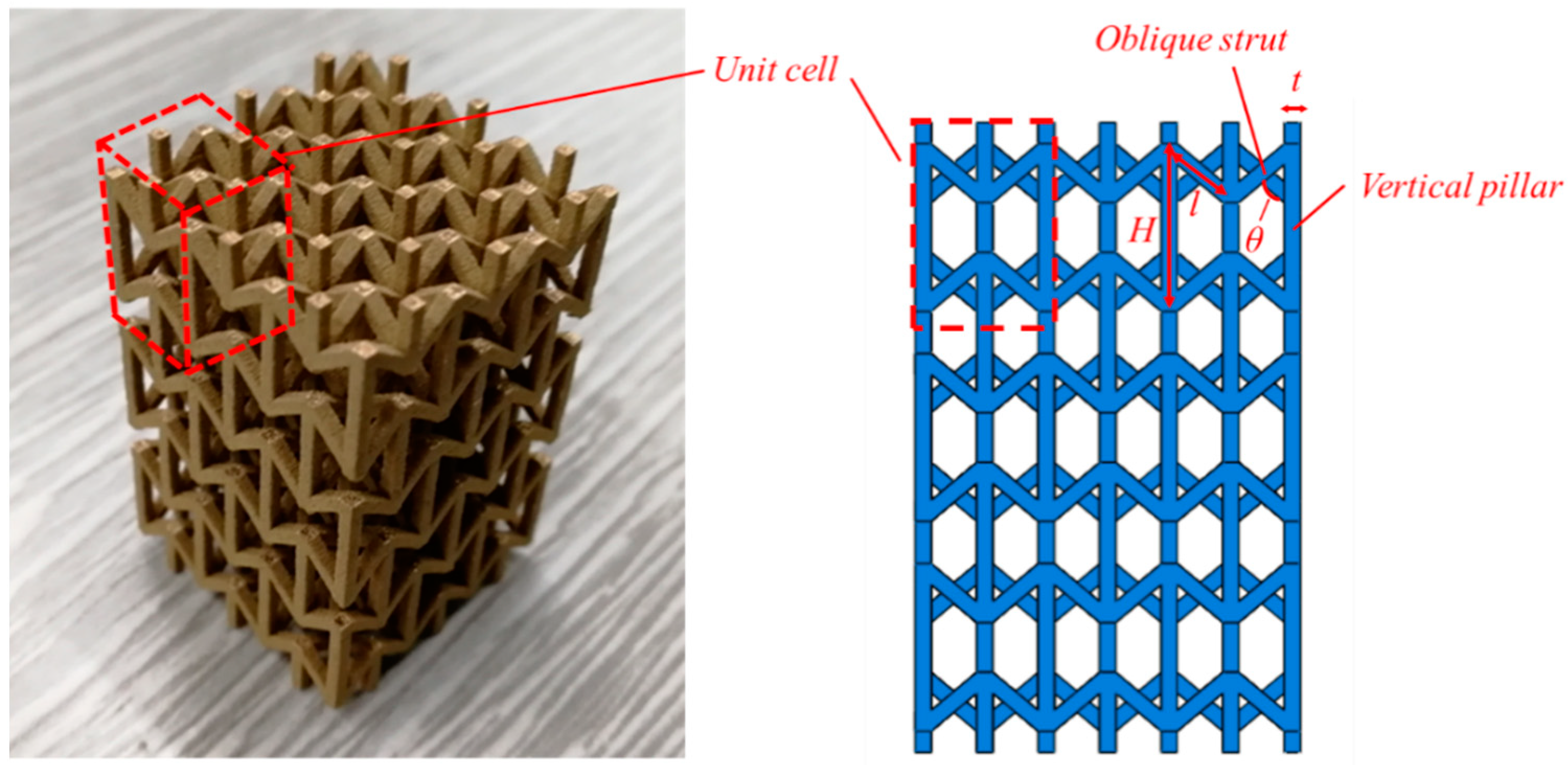
According to the previous research [22,24], the auxetic structure shown in Figure 1 is combined with several unit cells of umbrella shape, and the auxetic effect is caused by the enfoldment of the structure. In this research, the mechanical property of the bronze SLM structure and MA structure are studied. As the unit cell and the total structure is symmetrical, the mechanical behavior of the structure along the vertical direction during the compression process is important. The coefficient of the 3D auxetic structure has been shown: t is the thickness of the pillar, θ is the angle of the vertical and oblique strut, l is the length of oblique strut and H is the length of vertical pillar.
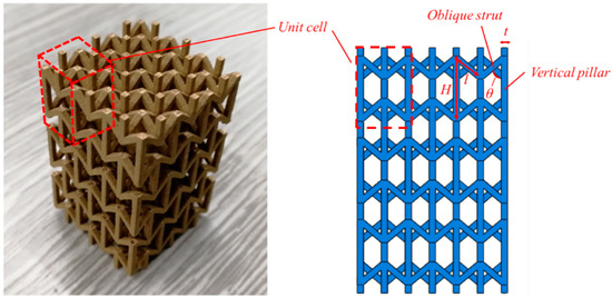
Figure 1.
3D auxetic structure.
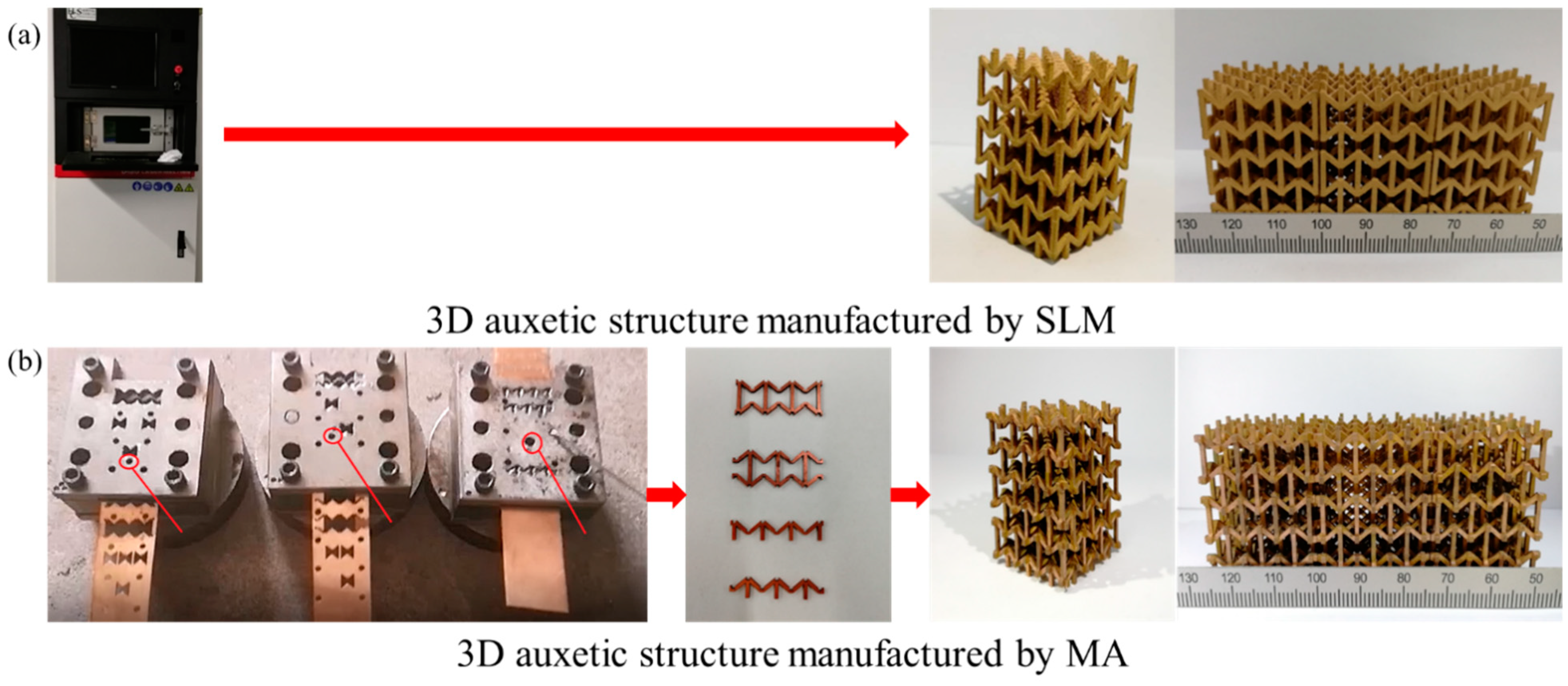
The SLM 3D auxetic structure is prepared via a Riton R120 metal 3D printer. It is a 3 × 3 × 3 layer 3D structure contains 27 unit cells. Side holders are applied to prevent the material falling from the structure during the 3D printing process, and then removed after 3D printing is finished. The MA 3D auxetic structure is produced by microforming and micro assemble process. A bronze foil is delivered in the progressive molding tool and the blanking process is conducted at each stage. Four kinds of 2D parts are produced via microforming and then assembled into a 3D auxetic structure, as shown in Figure 2.
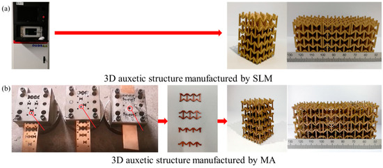
Figure 2.
3D auxetic strcutre manufactured by (a) SLM and (b) MA.
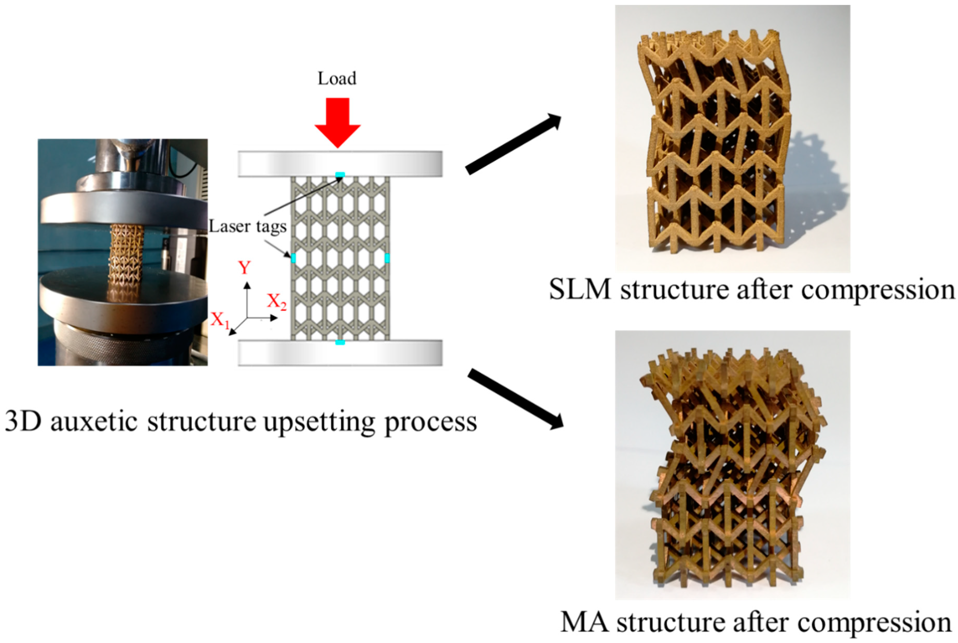
In order to compare the mechanical property of the SLM with the MA structure, bronze C5131 is applied in both of these two processes. The compression test is conducted on a Zwick/Roell Z050 testing machine, which is connected with a VideoXtens extensometer. Laser tags are bound on the top, bottom and both sides of the structure, and the maximum resolution of the extensometer is 0.01 μm. The punch speed of the testing machine is set to 0.1 mm/min to avoid the influence of strain rate, as shown in Figure 3. The horizontal and vertical strain is obtained via the video extensometer and the Poisson’s ratio is thus calculated.
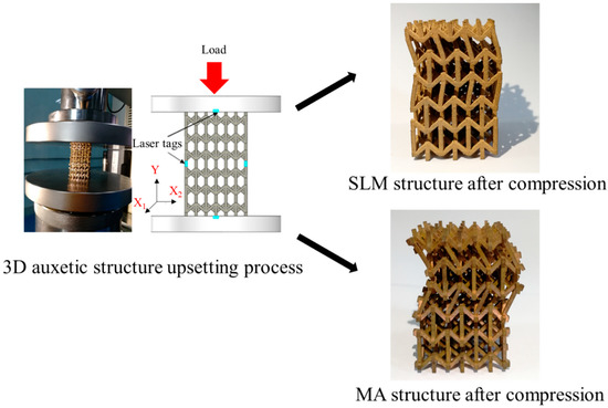
Figure 3.
Quasi-static compression test for SLM and MA 3D auxetic structure.
3. Result Analysis
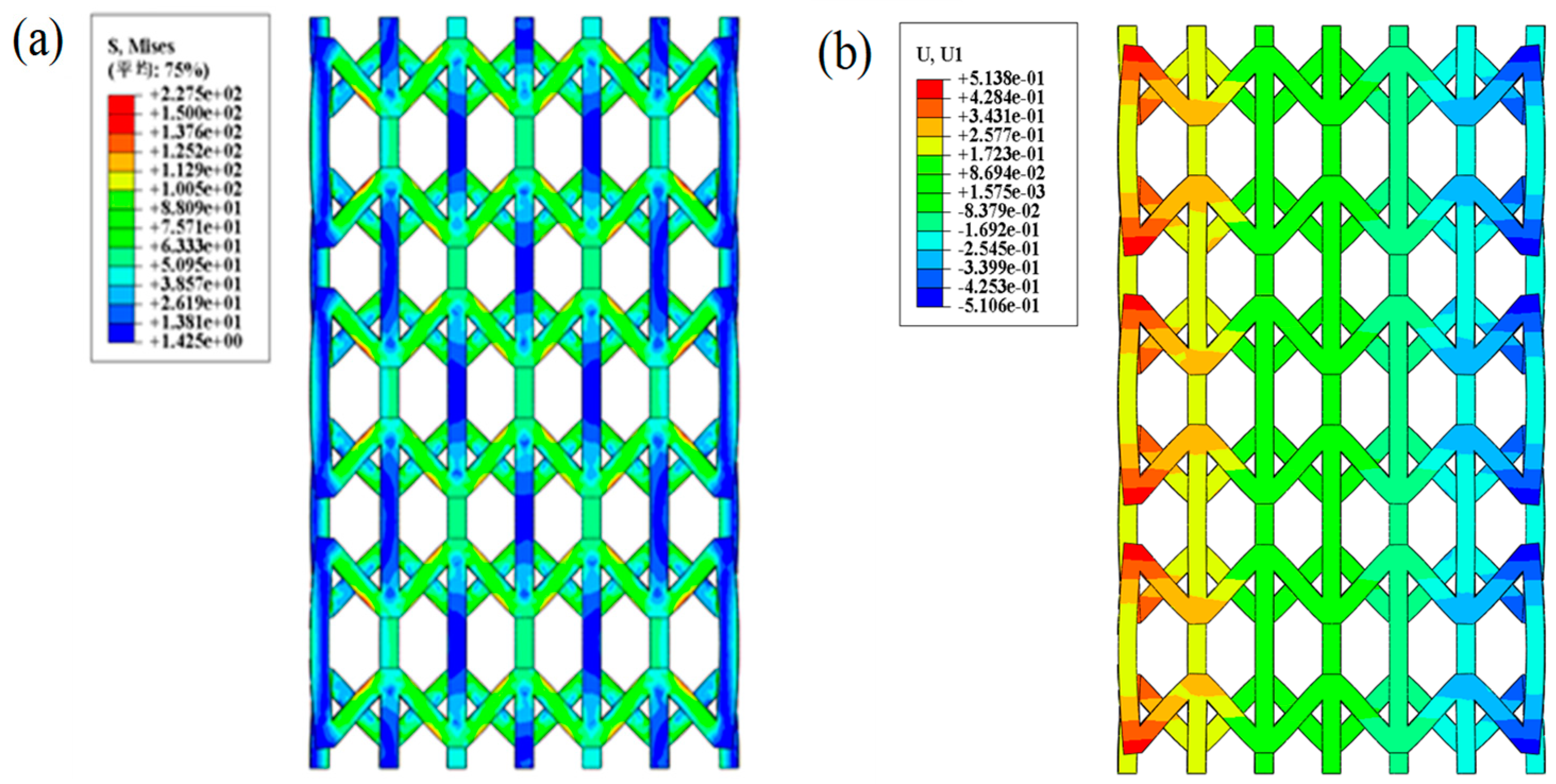
By conducting FE simulation, it is found that the stress concentration is on the oblique strut of the structure, and the bending process of the oblique strut is the main reason of the phenomenon of negative Poisson’s ratio [25], as shown in Figure 4. During the compression test, the vertical pillars of both sides of the auxetic structure move towards the central of the structure and thus achieve the lateral shrinkage of total structure.
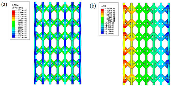
Figure 4.
FE simulation of compression test of the 3D auxetic structure: (a) Stress distribution (b) Stroke distribution.
3.1. Comparison of SLM and MA Structure
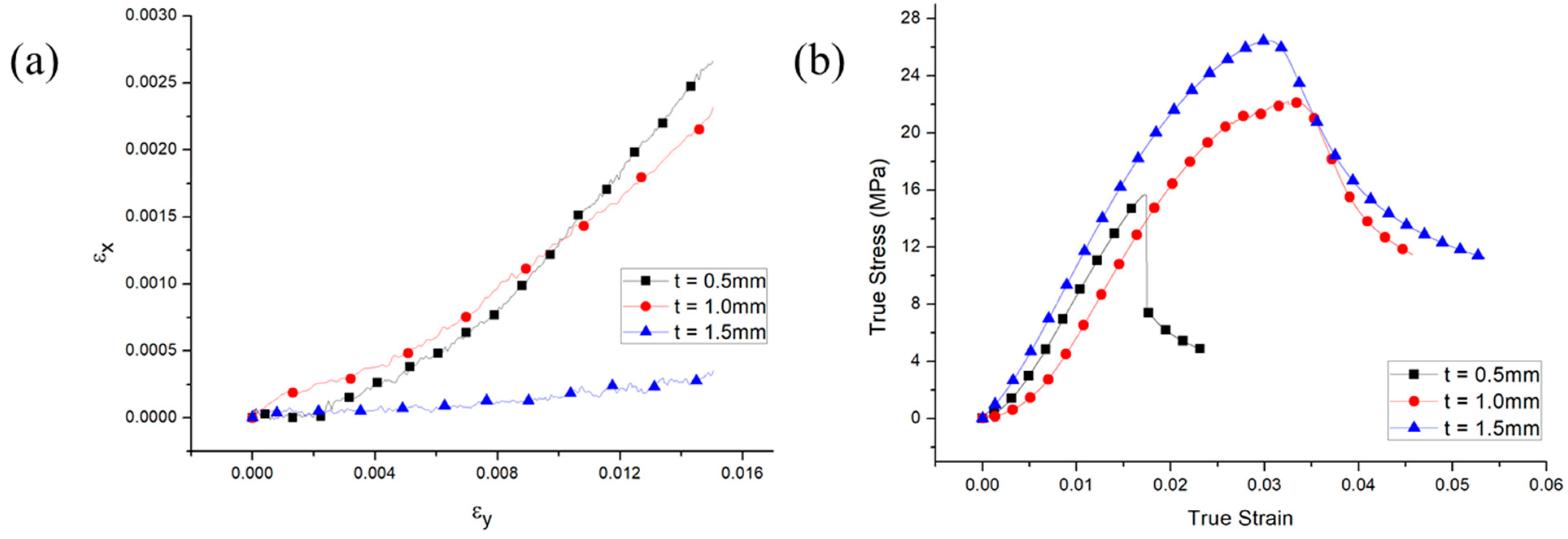
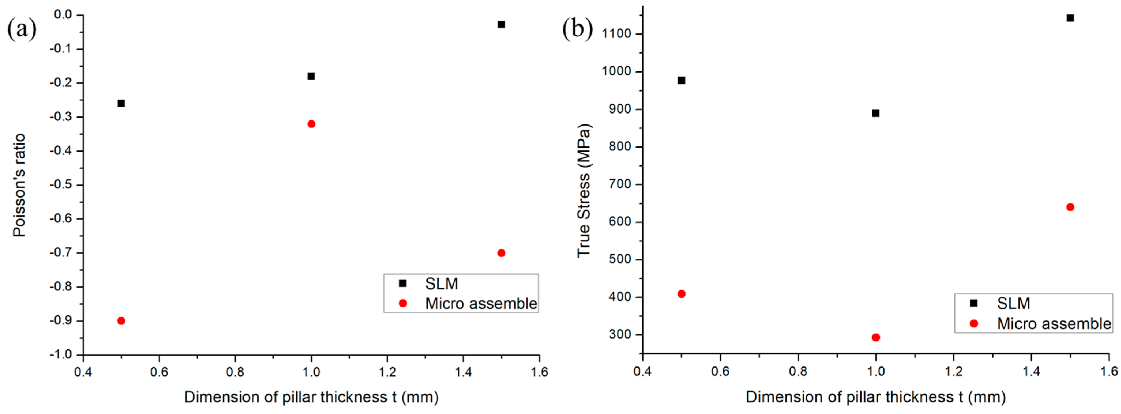
In this research, the Poisson’s ratio of different thickness of the vertical pillar is measured. For SLM structure, the pillar thickness of the inner layer of the structure is 1 mm, and the change of the dimension along horizontal direction is studied. As the 3D auxetic structure is symmetric, X1 and X2 direction are not distinguished, which means X2 will not be considered. The laser tags at the bottom and top of the structure will measure the displacement along the loading direction Y, and the laser tags at both sides will measure the displacement along the X direction. The slope of the stress-strain curve is the Young’s modulus and the slope of the εx and εy is the Poisson’s ratio of the structure. The data of εx and εy is obtained via the two laser extensometers of horizontal and vertical direction and the εx-εy curve is demonstrated in Figure 5a. It is found that the absolute value of the Poisson’s ratio has decreased with the pillar thickness. When the pillar thickness reach 1.5 mm, the slope of εx-εy curve is near 0, which means the auxetic effect of the structure no longer exists. As the thickness increases, more overlap areas exist at the joint point of the vertical pillar and oblique strut, and thus reduce the effective length of the oblique strut. From Figure 5b, it is found that the Young’s modulus of the 1.5 mm structure is the largest.
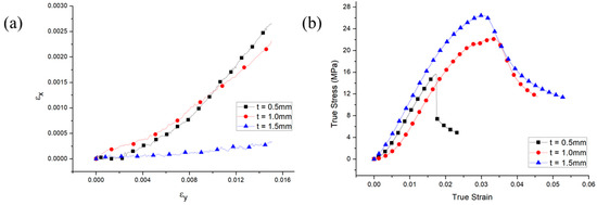
Figure 5.
The εx-εy curve and stress-strain curve of SLM auxetic structure of different pillar thickness. (a) εx-εy curve (b) Stress-strain curve.
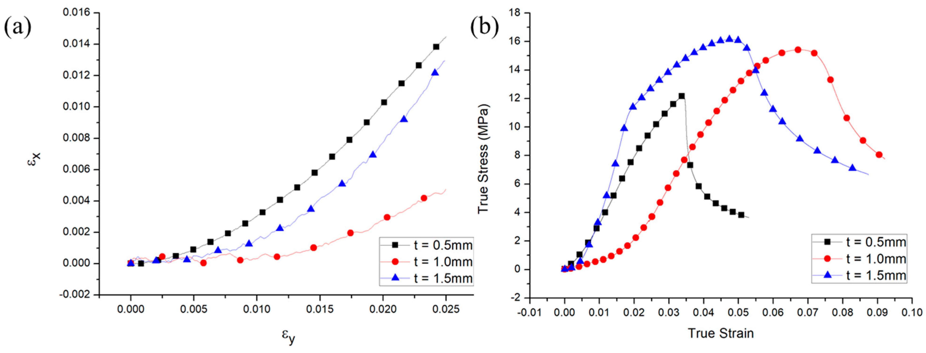
For MA structure, the Poisson’s ratio curve is shown in Figure 6a. It is found that the auxetic effect exists in the structure with all the three different pillar thickness, but the influence of the thickness is slightly different with the SLM structure. The Poisson’s ratio of the MA structure with 1.5 mm pillar thickness is much larger than the SLM structure, and the reason of this phenomenon may be due to the destabilization of the structure and has thus increased εx. For the specimens with the pillar thickness of 0.5 mm, the pillar contact area is relatively small. During the compression test, some of the bottom pillars may have “stick” on the die of the testing machine due to the friction force. Therefore, it is possible for these bottom pillars to buckling down and thus cause the Young’s modulus of 0.5 mm higher than 1 mm. In Figure 6b the curve of Young’s modulus of MA structure has been shown. The result is consistent with the one for SLM structure, which means the largest Young’s modulus is for the 1.5 mm thickness structure.

Figure 6.
The Poisson’s ratio εx-εy curve and stress-strain curve of MA auxetic structure of different pillar thickness. (a) εx-εy curve (b) Stress-strain curve.
At the beginning stage of the compression test, the flow stress of the MA structure increases slowly, because each component of MA structure has not been fully contacted in this stage, which is the reason that εy of MA structure is larger than SLM structure. When the components are fully contact, the flow stress of the structure increases rapidly with the increasing strain.
By comparing the mechanical properties of SLM and MA structure, it is found that the auxetic effect exists in both structures during the compression test. The auxetic effect is more obvious in MA structure as the absolute value of the Poisson’s ratio is larger than SLM structure, as shown in Figure 7a. Although the accuracy and clearance of each component has reduced the Young’s modulus of the MA structure, the comparison of the mechanical property between SLM and MA structure still proves that microforming and micro-assemble process is an effective way for manufacturing complex 3D auxetic structure. Meanwhile, it is found that another reason of the difference of the Young’s modulus of MA and SLM structure may be caused by the coarse grains due to sudden temperature change during the manufacturing process of SLM structure. The Young’s modulus of both structures decreases and then increase when the thickness of the pillar increases, as shown in Figure 7b.
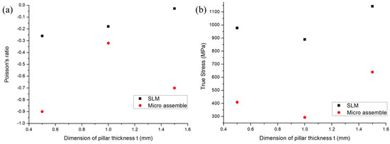
Figure 7.
Mechanical properties of SLM and MA 3D auxetic structure: (a) Poisson’s ratio (b) Young’s Modulus.
According to the result of the compression test, it is found that the upper layer of the auxetic structure will first destabilized from the elastic stage to plastic stage. This may cause by the friction between the structure and the MTS testing machine. The structure is taking axial compression stress and shear stress of the top and bottom surface because of the friction stress, which makes the structure destabilized. Micro cracks thus exist after structure destabilization, as shown in the SEM photo of Figure 8.
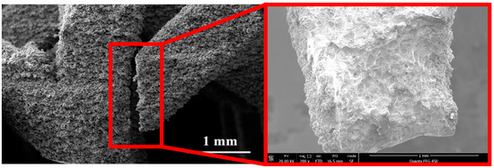
Figure 8.
The micro cracks in the oblique strut of the 3D auxetic structure.
3.2. Structural Size Effect and Structural Surface Layer Model
In macro and micro plastic deformation process, surface layer model has been widely used to reveal the stress contribution of different layer of the specimen. As the surface layer grains has free surface, its mechanical property is better than the inner layer grain. The size factor η, which is the proportion of the surface grains number to total grain number, is introduced into the surface layer model [26].
The basic expression of the surface layer model is:
In macro scaled plastic deformation process, the total grain number is very large and the size factor is thus small and the size effect is not obvious. When the size of the specimen decreases, or the grain size of the specimen increases, the size factor becomes larger and the stress contribution of the surface layer grain cannot be ignored. By using Equation (2), the stress strain relationship of a specimen affect by size effect can thus be obtained.
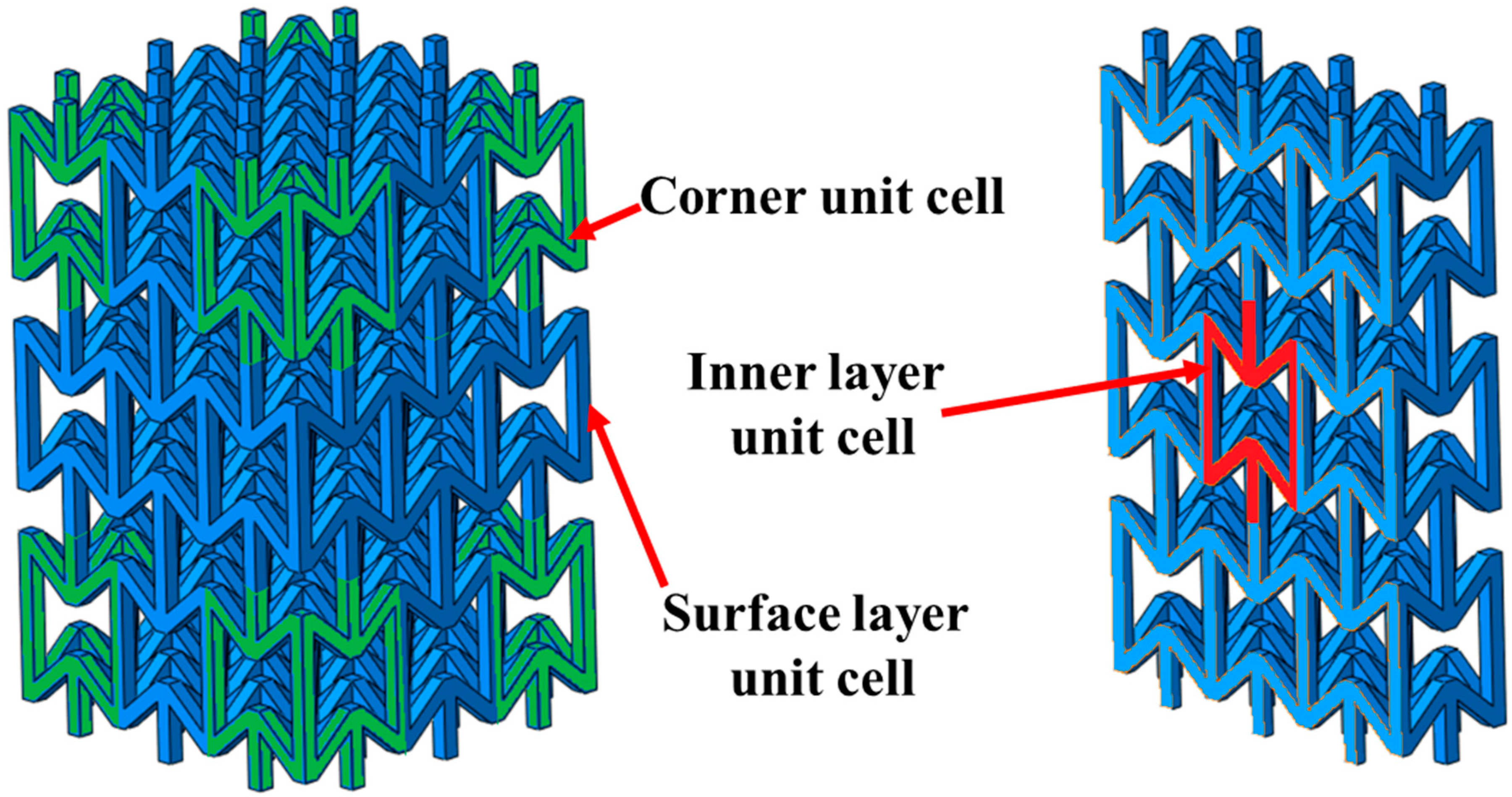
In this research, the so-called structural size effect is discovered and the structural surface layer model is provided to explain this phenomenon. As the 3D auxetic structure is consisted of several unit cells with the same size, the unit cells can be classified into corner unit cell, surface layer unit cells and inner layer unit cells, which is similar to previous research [26]. The corner unit cells and the surface layer unit cells have free surfaces while the inner layer unit cells haven’t, as shown in Figure 9. The unit cells in the central area, which are marked with red, are defined as the inner layer unit cells. The corner unit cells and surface layer unit cells have at least one free surface, which are marked with green and blue.
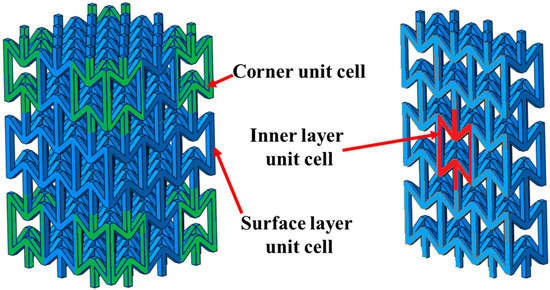
Figure 9.
Structure size effect in 3D auxetic structure.
In Wang’s previous research [22], the reduction of the effective length of the 3D auxetic structure is consisted of and , as shown in Equation (3):
where and . In this equation, the reduction of a single unit cell under compression stress is related with the pillar thickness t and the re-entrant angle. The coefficient is a semi-empirical coefficient which is calculated via curve fitting. This model is quite accurate according to the experimental and simulation result, but the stress-strain relationship of the 3D auxetic is not easy to obtain.
In this research, an uncoupled model based on Lemaitre’s damage model [27] is presented. According to Lemaitre’s model, the damage value D of material is defined as the effective area to the entire area of a unit cell selected from the material S, and can be represented as,
And the damage equivalent stress is similar to the Von Mises stress and can be represented as,
where is the Poisson’s ratio and is the mean stress.
For inner unit cells of the 3D auxetic structure, the damage value D can be applied as the volume of the vertical pillar and the oblique structure to the volume of a unit cell with a solid core according to Equation (4), which is:
And for surface auxetic structure, the damage value D can be distinguished into two parts, which is the surface layer unit cells and the corner unit cells of the 3D auxetic structure. These two kinds of structures can be represented as:
When the auxetic structure contains a large number of unit cells, the proportion of the surface and corner unit cells will be very small. For example, the auxetic structure contains 100 × 100 × 100 unit cells have 8 corner unit cells and 58,800 surface unit cells, and the number of the inner unit cells is 941,192, the size factor is 5.88% and the structure size effect is not obvious. The auxetic structure contains 10 × 10 × 10 unit cells have 8 corner unit cells and 480 surface unit cells, and the number of the inner unit cells is 512, the size factor is 48.8%. However, when the structure size or the total number of unit cells is becoming smaller, the size factor becomes larger. In this research, the auxetic structure contains 3 × 3 × 3 unit cells and the size factor of the auxetic structure is 96.3%, which is consisted of 29.6% of corner unit cells and 66.7% of surface layer unit cells. Therefore, the equivalent stress of a 3D auxetic structure with 3 × 3 × 3 unit cells can be represented as:
Equation (9) is the full version of the structure surface layer model.
3.3. Model Application
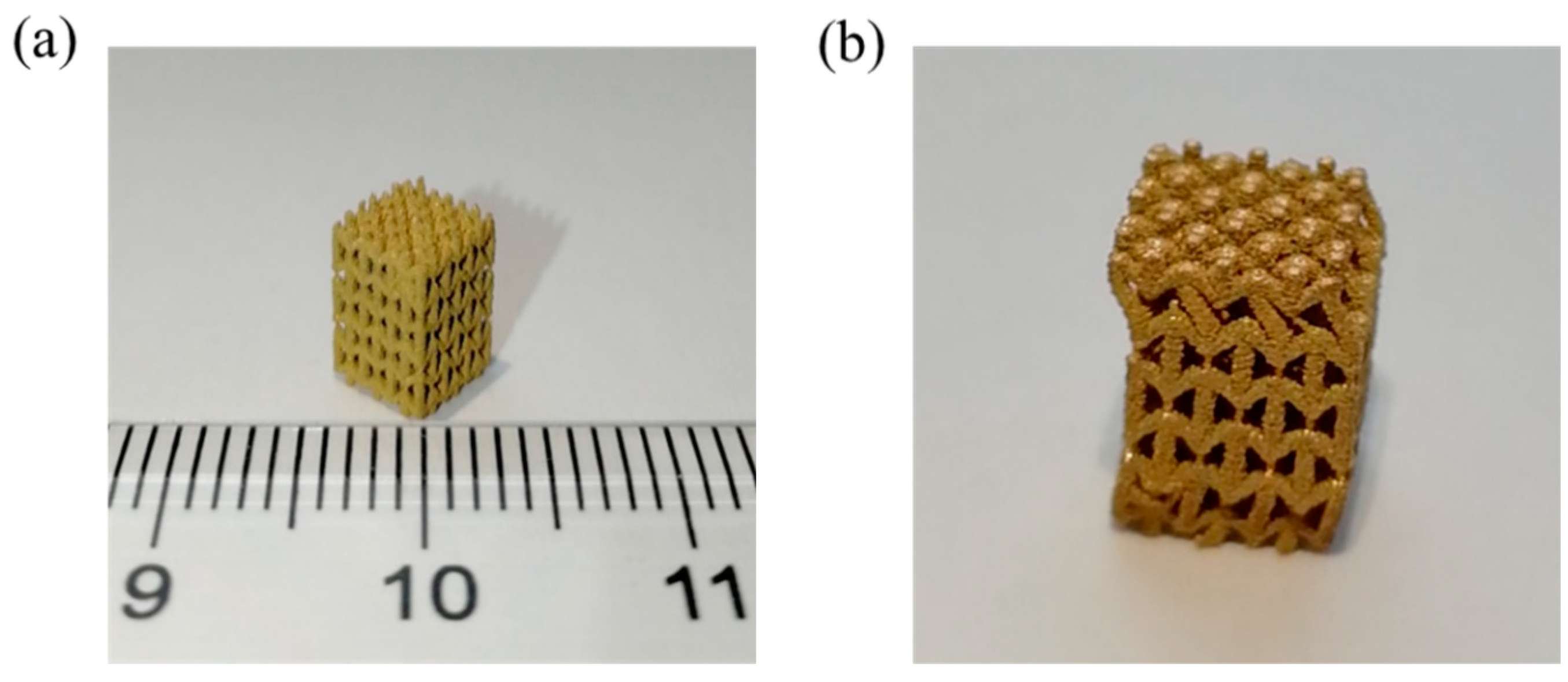
In order to examine the accuracy of the model above, the SLM auxetic structure contains 3 × 3 × 3 unit cells with smaller size are manufactured, as shown in Figure 10a. Its overall dimension is 4.8 × 4.8 × 7.8 mm. The compression test is conducted and the result is compared with simulation result.
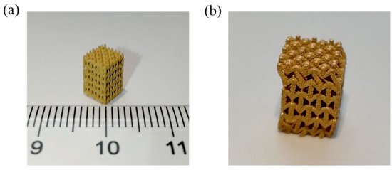
Figure 10.
Micro scaled 3D auxetic structure. (a) Before compression test (b) After compression test.
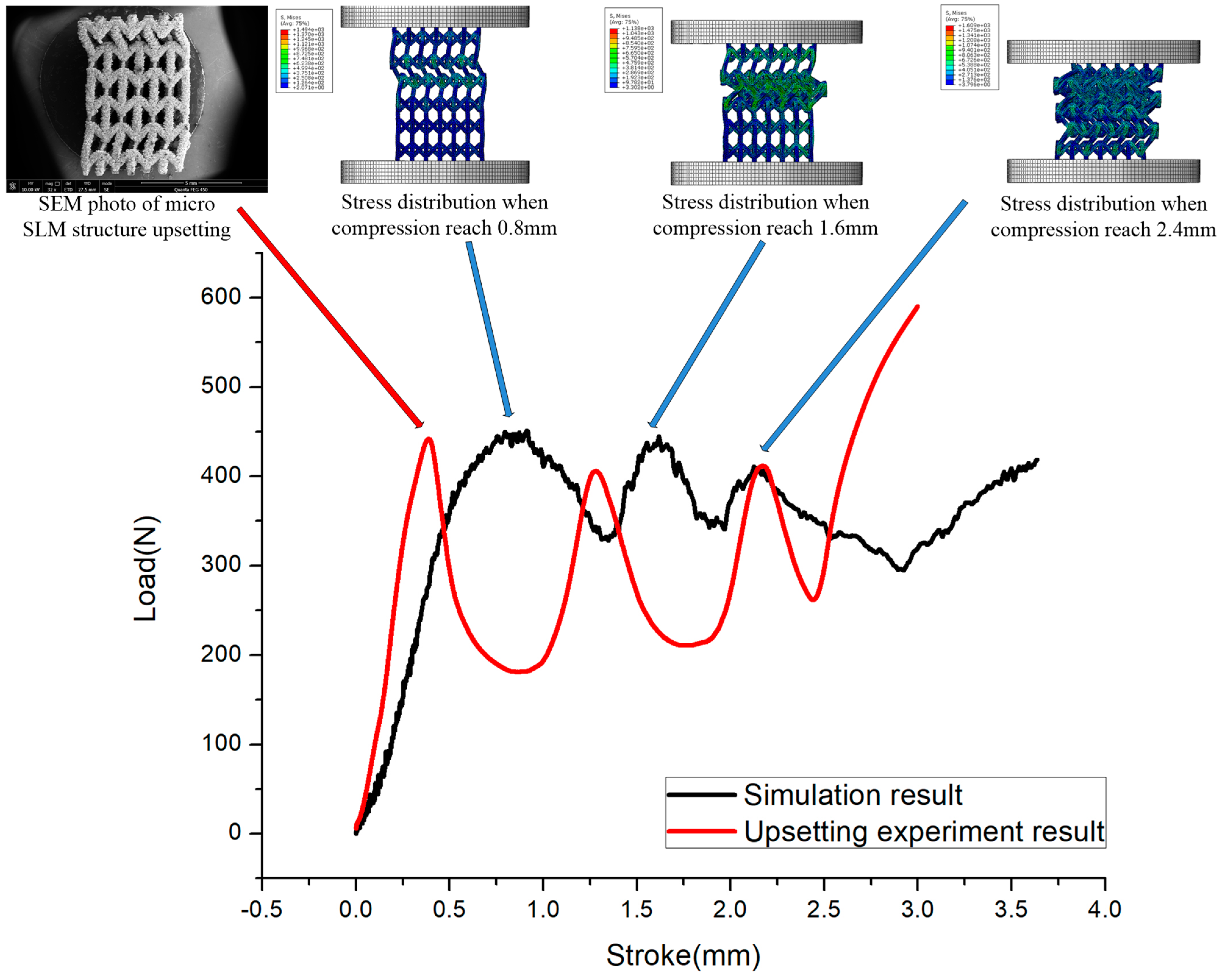
It is found that the top layer of the auxetic structure is first destabilized during the compression test, and the position of destabilization is similar to macro scaled auxetic structure, as shown in Figure 10b. The Load-stroke curve is obtained, and it is consistent with Li’s [23] research, as shown in Figure 11. The main reason of the cyclic load-stroke is due to the structure failure during the compression process. The vertical pillars are always under compression first during the compression test, and stress will concentrate on other pillars if one of them bends. The rest of the pillars will fail instantly and finally all the unit cells in the same layer will collapse, and the next layer of the structure will repeat this process. As each pillar of the structure is close to each other, the corner of the unit cell will contact when layer collapse, and the load will increase. It is obvious that the number of the cyclic equals to the number of the layer of the structure.
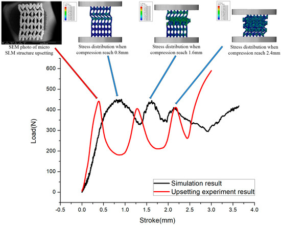
Figure 11.
Load-stroke curve of micro auxetic structure obtain via FE simulation and actual experiment.
The simulation result has also been shown in Figure 11. It has the same number of cyclic load-stroke as the experiment result. The maximum load of each cyclic obtained via FE simulation is close to the experiment result, which proves that the structure surface layer model can be used to predict the mechanical behavior of the auxetic structure. The stroke of the simulation result is slightly different from the experiment. This is mainly because some of the supporting structure inside the SLM structure has not been fully removed, thus enhance the mechanical property of the structure.
4. Conclusions
A 3D auxetic structure manufactured by SLM and MA has been conducted in this research. The 3D structures with different pillar thickness have been produced to study the structure size effect of the 3D auxetic structure. By comparing the simulation and experiment result, it is found that the negative Poisson’s ratio exists in both the SLM and MA structure during the compression test, and the Poisson’s ratio decrease when the pillar thickness increase.
During the elastic stage of the compression test, the auxetic effect of MA structure is more obvious, but the Young’s modulus is relatively small. In the plastic stage, both SLM and MA structure has destabilized. Micro cracks exist on SLM structure, and the surface quality of MA structure is good. By establishing the structure surface layer model of 3D auxetic structure, the influence of structure size effect is revealed and quantified. Comparing with the experiment result, it is found that the structure surface layer model is relatively helpful for the prediction of the mechanical behavior of 3D auxetic structure.
Author Contributions
Conceptualization, J.R.; methodology, J.R.; software, G.C.; validation, F.Z. and L.X.; formal analysis, J.R.; investigation, T.X.; resources, F.G.; data curation, J.R.; writing—original draft preparation, J.R.; writing—review and editing, J.R.; visualization, J.R.; supervision, F.G.; project administration, F.G.; funding acquisition, T.X. All authors have read and agreed to the published version of the manuscript.
Funding
This research was funded by [The National Natural Science Foundation of China] grant number [51705333, 52005341], [The Natural Science Foundation of GuangDong Province] grant number [2017A030310352], [The open project of key laboratory of GuangDong Province] grant number [PEM201605], [The Shenzhen Science and Technology Program] grant number [JCYJ20160520175255386].
Institutional Review Board Statement
Not applicable.
Informed Consent Statement
Not applicable.
Data Availability Statement
The data presented in this study are available on request from the corresponding author.
Acknowledgments
The work described in this paper was supported by the grants from the National Natural Science Foundation of China (Grant No. 51705333, 52005341), the Natural Science Foundation of GuangDong Province (Grant No. 2017A030310352), the open project of key laboratory of GuangDong Province (PEM201605), the Shenzhen Science and Technology Program (Grant No. JCYJ20160520175255386).
Conflicts of Interest
The authors declare no conflict of interest.
References
- Gunton, D.J.; Saunders, G.A. The Young’s modulus and Poisson’s ratio of arsenic, antimony and bismuth. J. Mater. Sci. 1972, 7, 1061–1068. [Google Scholar] [CrossRef]
- Lakes, R. Foam structures with a negative Poisson’s ratio. Science 1987, 23, 1038–1040. [Google Scholar] [CrossRef]
- Evans, K.E.; Caddock, B.D. Microporous materials with negative Poisson’s ratios: II. Mechanisms and interpretation. J. Phys. D: Appl. Phys. 1989, 22, 1883–1887. [Google Scholar] [CrossRef]
- Evans, K.E.; Nkansah, M.A.; Hutchinson, I.J.; Rogers, S.C. Molecular network design. Nature 1991, 353, 124. [Google Scholar] [CrossRef]
- Wojciechowski, K.W. Constant thermodynamic tension Monte Carlo studies of elastic properties of a two-dimensional system of hard cyclic hexamers. Mol. Phys. 1987, 61, 1247–1258. [Google Scholar] [CrossRef]
- Wojciechowski, K.W. Two-dimensional isotropic system with a negative Poisson ratio. Phys. Lett. A 1989, 137, 60–64. [Google Scholar] [CrossRef]
- Wojciechowski, K.W.; Brańka, A.C. Negative Poisson ratio in a two-dimensional “isotropic” solid. Phys. Rev. A Gen. Phys. 1989, 40, 7222. [Google Scholar] [CrossRef] [PubMed]
- Kolpakov, A.G. Determination of the average characteristics of elastic frameworks. J. Appl. Math. Mech. 1985, 49, 739–745. [Google Scholar] [CrossRef]
- Hoover, W.G.; Hoover, C.G. Searching for auxetics with DYNA3D and ParaDyn. Phys. Status Solidi B 2005, 242, 585–594. [Google Scholar] [CrossRef] [Green Version]
- Pozniak, A.A.; Wojciechowski, K.W. Poisson’s ratio of rectangular anti-chiral structures with size dispersion of circular nodes. Phys. Status Solidi 2014, 251, 367–374. [Google Scholar] [CrossRef]
- Bilski, M.; Pigłowski, P.M.; Wojciechowski, K.W. Extreme Poisson’s Ratios of Honeycomb, Re-Entrant, and Zig-Zag Crystals of Binary Hard Discs. Symmetry 2021, 13, 1127. [Google Scholar] [CrossRef]
- Smardzewski, J.; Maslej, M.; Wojciechowski, K.W. Compression and low velocity impact response of wood-based sandwich panels with auxetic lattice core. Eur. J. Wood Wood Prod. 2021, 79, 797–810. [Google Scholar] [CrossRef]
- Baughman, R.H.; Shacklette, J.M.; Zakhidov, A.A.; Stafstrom, S. Negative Poisson’s ratios as a common feature of cubic metals. Nature 1998, 392, 362–365. [Google Scholar] [CrossRef]
- Piglowski, P.M.; Narojczyk, J.W.; Wojciechowski, K.W.; Tretiakov, K.V. Auxeticity enhancement due to size polydispersity in fcc crystals of hard-core repulsive Yukawa particles. Soft Matter. 2017, 13, 7916–7921. [Google Scholar] [CrossRef] [PubMed] [Green Version]
- Narojczyk, J.W.; Wojciechowski, K.W. Elastic properties of the fcc crystals of soft spheres with size dispersion at zero temperature. Phys. Status Solidi B 2008, 245, 606–613. [Google Scholar] [CrossRef]
- Narojczyk, J.W.; Wojciechowski, K.W. Poisson’s Ratio of the f.c.c. Hard Sphere Crystals with Periodically Stacked (001)-Nanolayers of Hard Spheres of Another Diameter. Materials 2019, 12, 700. [Google Scholar] [CrossRef] [Green Version]
- Almgren, R. An isotropic three-dimensional structure with Poisson’s ratio. J. Elast. 1985, 15, 427–430. [Google Scholar]
- Larsen, U.D.; Sigmund, O.; Bouwstra, S. Design and Fabrication of Compliant Micromechanisms and Structures with Negative Poisson’s Ratio. J. Microelectromechanical Syst. 1997, 6, 99–106. [Google Scholar] [CrossRef] [Green Version]
- Grima, J.N.; Gatt, R.; Alderson, A.; Evans, K.E. On the potential of connected stars as auxetic systems. Mol. Simul. 2005, 31, 925–935. [Google Scholar] [CrossRef] [Green Version]
- Shokri, R.M.; Prawoto, Y.; Ahmad, Z. Analytical solution and finite element approach to the 3D re-entrant structures of auxetic materials. Mech. Mater. 2014, 74, 76–87. [Google Scholar] [CrossRef]
- Hengsbach, S.; Lantada, A.D. Direct laser writing of auxetic structures: Present capabilities and challenges. Smart Mater. Struct. 2014, 23, 085033. [Google Scholar] [CrossRef]
- Wang, X.; Li, X.; Ma, L. Interlocking assembled 3D auxetic cellular structures. Mater. Des. 2016, 99, 467–476. [Google Scholar] [CrossRef] [Green Version]
- Li, Y.; Cormier, D.; West, H.; Harrysson, O.L.A.; Knowlson, K. Non-stochastic Ti–6Al–4V foam structures with negative Poisson’s ratio. Mater. Sci. Eng. A 2012, 558, 579–585. [Google Scholar]
- Evans, K.E.; Nkansah, M.A.; Hutchinson, I.J. Auxetic foams: Modelling negative Poisson’s ratios. Acta Metall. Mater. 1994, 42, 1289–1294. [Google Scholar] [CrossRef]
- Schwerdtfeger, J.; Schury, F.; Stingl, M.; Wein, F.; Singer, R.F.; Körner, C. Mechanical characterisation of a periodic auxetic structure produced by SEBM. Phys. Status Solidi B 2012, 249, 1347–1352. [Google Scholar] [CrossRef]
- Ran, J.Q.; Fu, M.W.; Chan, W.L. The influence of size effect on the ductile fracture in micro-scaled plastic deformation. Int. J. Plast. 2013, 41, 65–81. [Google Scholar] [CrossRef]
- Lemaitre, J. A continuous damage mechanics model for ductile fracture. Trans. Asme J. Eng. Mater. Technol. 1985, 107, 83–89. [Google Scholar] [CrossRef]

Publisher’s Note: MDPI stays neutral with regard to jurisdictional claims in published maps and institutional affiliations. |
© 2022 by the authors. Licensee MDPI, Basel, Switzerland. This article is an open access article distributed under the terms and conditions of the Creative Commons Attribution (CC BY) license (https://creativecommons.org/licenses/by/4.0/).