Article

Study on the Influence of Flow Distribution Structure of Piston Pump on the Output of Pulsation Pump

School of Mechanical Engineering, Qilu University of Technology (Shandong Academy of Sciences), Jinan 250000, China
*
Author to whom correspondence should be addressed.
Processes 2022, 10(6), 1077; https://doi.org/10.3390/pr10061077
Submission received: 18 May 2022 / Revised: 24 May 2022 / Accepted: 25 May 2022 / Published: 27 May 2022
(This article belongs to the Special Issue Design and Optimization Method of Pumps)

Abstract

:
According to the working principle of the A10VNO swashplate axial piston pump, the output flow model of an axial piston pump in an ideal state and the output flow theoretical model of an axial piston pump considering the leakage and flow distribution process are established. The output flow pulsations of odd and even piston pumps are simulated and analyzed by Matlab, and the influence of a closed dead angle and a mismatch angle of the port plate on the output flow pulsation of the pump is obtained. Based on the theoretical model, AMESim is used to establish the overall model of the axial piston pump considering leakage, flow distribution process and oil compressibility under constant working conditions. By setting six different flow distribution boundary conditions corresponding to the theoretical research, the influence of flow distribution plate structure on pump output flow pulsation is studied. A test-bed was built and verified by experiments. The results show that when the mismatch angle of the valve plate is 3–5° and the dead angle is 6–10°, the difference between the output flow pulsations of the odd and even piston pumps is very small, so in the hydraulic pump hydraulic motor system, when the hydraulic pump is used as a hydraulic motor under the condition of power recovery, the odd number or adjacent even number of hydraulic motors are appropriate.

1. Introduction

Due to its structural characteristics, the axial piston pump will produce flow pulsations in the working process. The flow pulsations are bound to cause pressure pulsations. The flow and pressure pulsations will directly affect the service life and service performance of the pump, and produce a lot of noise, which will directly affect the performance of the whole hydraulic system [1]. The noise generated by axial piston pump mainly comes from the flow distribution process [2]. In practical work, when each piston cavity switches from the valve plate in the high- and low-pressure areas, it will produce large flow backflow and hydraulic impact, which will cause pump output pressure and flow pulsation, generate flow distribution noise and reduce system efficiency [3]. Therefore, the influence of port plate structure should be considered in the research of reducing pump output flow pulsation and reducing its distribution noise. Many scholars have done a lot of research on the structure of the port plate. The method of optimizing the size of the damping groove and damping hole of the port plate is widely used, and some results have been obtained.
A large number of theoretical and simulation analyses have been carried out on the flow pulsation characteristics of swashplate axial piston pumps. Zhang et al. [4,5] found that the main influencing factor of the flow pulsation of the piston pump under ideal working conditions is the number of plungers, and it was concluded that an odd number of plunger pumps is obviously better than an even number of plunger pumps. Through theoretical analysis, Wang et al. [6,7] concluded that considering the leakage and flow distribution geometric factors, the number and parity of the plunger of the plunger pump are not the decisive factors of the flow pulsation. The flow pulsation rates of the pump with an odd number of plungers and an even number of plungers are almost the same, and both are higher than the flow pulsation rate under the ideal working conditions. Na et al. [8,9] analyzed the influence of oil compressibility and damping groove structure on the flow pulsation of a piston pump. Yan et al. [10], through modeling and simulation analysis of the axial piston pump in AMESim, concluded that the structure and leakage parameters of the piston pump have an important impact on the flow pulsation. Zhang et al. [11] modeled and simulated the axial piston pump in AMESim, and concluded that the actual flow pulsation of the piston pump is related to the load pressure. Harrison et al. [12,13] optimized the structure of the valve plate. The research results show that two one-way valves are set in the oil suction and discharge tank, which can effectively reduce the flow pulsation of the plunger pump. Liu et al. [14] comprehensively analyzed the main influencing factors of the structure and performance of the plunger pump and concluded that the optimal number of plungers is nine. Bergada et al. analyzed the leakage, pressure, force and torque of key friction pairs; established a new theoretical model of pump output flow; and focused on the influence of fluid properties on the movement of plunger pair. In addition, the influence of the slipper curved surface on hydrostatics and dynamics was also studied and verified by experiments [15,16,17].
In this paper, the author takes the A10VNO swashplate axial piston pump developed by a company as the research object, establishes the hydraulic model of the axial piston pump in AMESim, simulates and analyzes its flow pulsation characteristics, analyzes the influence of port plate structure on the flow pulsation of the axial piston pump through continuous debugging parameters and builds an experimental platform for verification.

2. Working Principle of Valve Plate of Axial Piston Pump

The main working parts of the A10VNO swashplate axial piston pump are swashplate, cylinder block, drive shaft, plunger, sliding shoe, return plate, port plate, variable piston rod, etc. [18,19]. The inclination angle of the swashplate is γ. Under constant working conditions, when the prime mover drives the cylinder block 3 to rotate through the drive shaft, due to the action of the swashplate, the plunger is forced to make periodic reciprocating motions in the cylinder block, and the volume of the sealing cavity between each plunger and the cylinder block increases and decreases. When the oil absorption and oil drainage are realized through the arc oil absorption window and oil drainage window of the port plate, as shown in Figure 1, the port plate is provided with two axially symmetrical oil suction grooves and oil discharge grooves, two centrally symmetrical vibration reduction grooves (holes) and the upper and lower dead center axes have a certain included angle with the symmetrical axis of the oil suction and discharge groove, that is, the mismatch angle φ 0 forming staggered oil distribution, and the valve plate is provided with a closed compression area, Δ φ 1 , while Δ φ 2 is the dead angle of pre-lifting and pressure relief, so that the pressure in the plunger cavity can be pre-boosted or pre-relieved, and the pressure remains stable when switching between high- and low-pressure areas. The plunger cavity avoids oil suction and drainage at the upper and lower dead centers, but connects with the oil drainage groove at φ 0 + Δ φ 1 /2 and stops oil drainage at π − Δ φ 2 /2 + φ 0 .

3. Analysis of Output Flow Pulsation of Axial Piston Pump

3.1. Analysis of Output Flow Pulsation of Axial Piston Pump under Constant Working Conditions

Under constant working conditions, regardless of the leakage and oil distribution process, the instantaneous output flow of a single plunger when discharging oil [20] is
Q 0 i = A υ i = A ω R tan γ sin φ i
where ω is the rotation angle speed of the cylinder block, R is the radius of plunger distribution circle, φ i is the rotation angle of the i plunger and υ i is the movement speed of the i plunger in the plunger pump relative to the cylinder block.
Without considering leakage, flow distribution and other factors, assuming that the number of plungers connected to the oil discharge chamber at a certain time is m, the number of plungers is z, the theoretical instantaneous output flow Q0 of the plunger pump is
Q 0 = Q 01 + Q 02 + Q 03 + + Q 0 m = i = 1 m Q 0 i = A ω R tan γ i = 1 m sin φ i = A ω R tan γ i = 1 m sin φ 1 + i 1 α
According to Formula (2):
Q 0 = A ω R tan γ i = 1 m sin φ 1 + i 1 α = A ω R tan γ sin φ 1 + m 1 z π sin m π z sin π z
The flow pulsation rate of plunger pump [21] is δ 1 :
δ 1 = Q 0 , max Q 0 , min Q t · 100 % = Q 0 , max Q 0 , min
where Q 0 , max maximum instantaneous output flow, Q 0 , min is the minimum instantaneous output flow, Q 0 , max is the maximum value of the ratio of instantaneous output flow to average theoretical flow and Q 0 , min is the minimum value of the ratio of instantaneous output flow to average theoretical flow.
Set up α is the angle between two adjacent plungers, α = 2π/ z. When the number of plungers is odd, the number of plungers m connected to the oil discharge chamber at a certain time can be divided into two cases [22,23,24,25]: 0 ≤ φ 1 < α/2 when the number of plungers in the oil drainage area m = (z + 1)/2 and α/2 ≤ φ 1 ≤ α when the number of plungers in the oil drainage area m = (z − 1)/2. For an even number of plungers m = z/2.
When the number of plungers is odd, substitute m into Equation (3) and simplify the arrangement to obtain:
Q 0 = A ω R tan γ cos π 2 z φ 1 2 sin π 2 z 0 φ 1 < α / 2 A ω R tan γ cos 3 π 2 z φ 1 2 sin π 2 z α / 2 φ 1 α
The output flow pulsation of plunger pump is analyzed. According to Formulas (4) and (5):
Q 0 = Q 0 Q t = π cos π 2 z φ 1 2 z sin π 2 z                         0 φ 1 < α / 2 π cos 3 π 2 z φ 1 2 z sin π 2 z                         α / 2 φ 1 < α
When the number of plungers is even, substitute m into Equation (3) and simplify the arrangement to obtain:
Q 0 = A ω R tan γ cos φ 1 π z sin π z
The output flow pulsation of the plunger pump is analyzed according to Formulas (3) and (7):
Q 0 = Q 0 Q t = π cos φ 1 π z z sin π z
According to Equations (6) and (8), under ideal conditions, the output flow pulsation of the axial piston pump is closely related to the number of plungers.
For the plunger pump with an odd number of plungers, when 0 ≤ φ 1 < α/2 and α/2 ≤ φ 1 α cases and when the number of plungers is z = 5, 7, 9 or 11, the output flow pulsation curve of the odd number of plunger pumps under constant working conditions can be obtained by programming and analysis in Matlab, as shown in Figure 2.
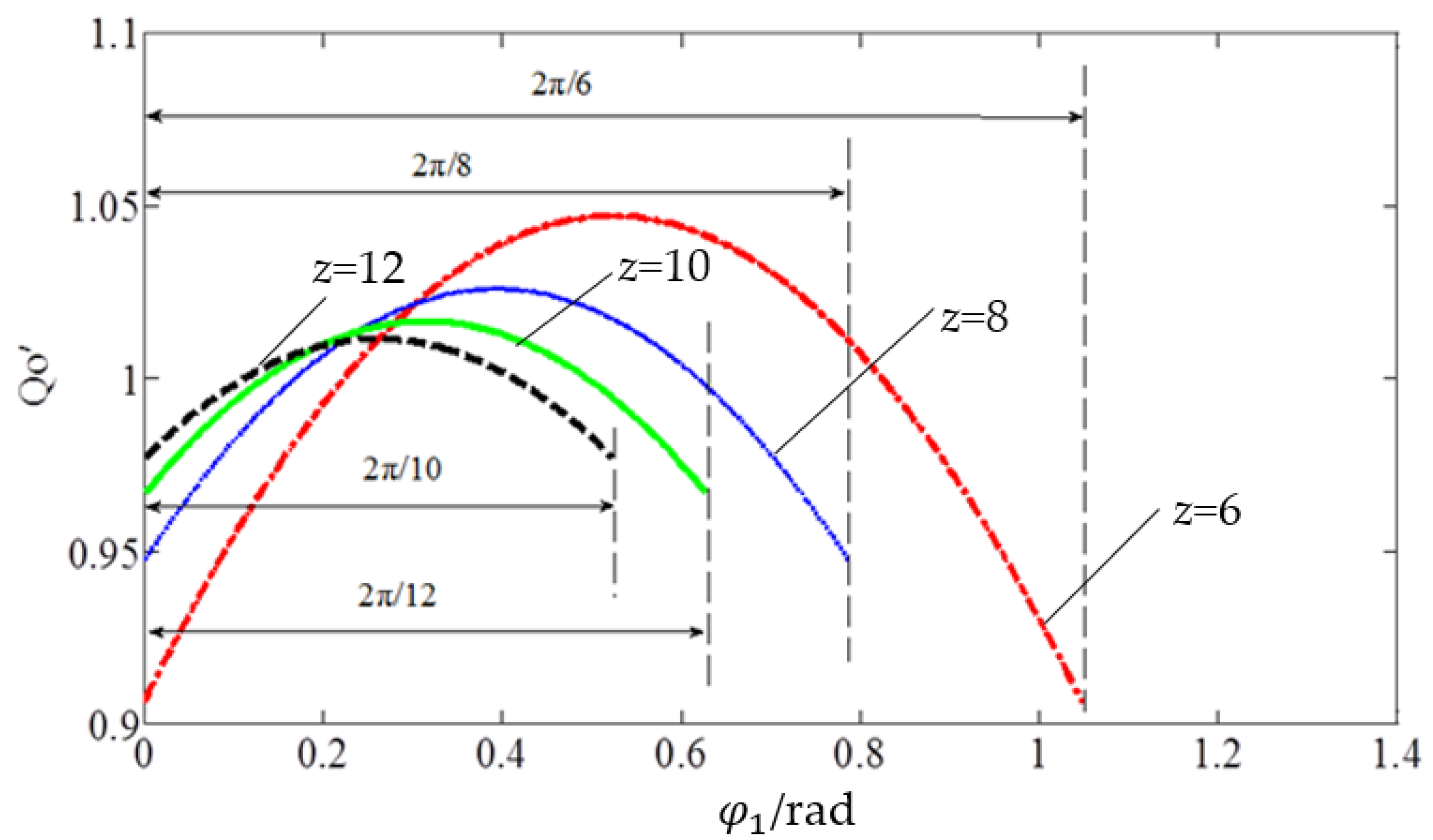
For the piston pump with an even number of plungers, i.e., when z = 6, 8, 10 and 12, the output flow pulsation curve of the even number of plunger pumps under the condition of constant displacement can be obtained by programming and analysis in Matlab, as shown in Figure 3.
Under constant working conditions, it can be seen from Figure 2 and Figure 3:
For the odd number (5, 7, 9, 11) of piston pumps, when the cylinder body turns on an angle of 2π/z, the instantaneous output flow has two pulsations, the flow pulsation period is π/z and the pump output flow is an ideal cosine curve. When φ1 is π/2z and 3π/2z, the flow has two maximum values, respectively, and the flow pulsation frequency is f = ω/T = ωz/2π. With the increase of the number of plungers, the output flow pulsation of the pump decreases significantly.
For an even number (6, 8, 10, 12) of piston pumps, when the cylinder body turns to an angle of 2π/z, the instantaneous output flow has a pulsation, the flow pulsation period is 2π/z and the pump output flow is also an ideal cosine curve. When φ 1 is π/z, the flow has a maximum value and the flow pulsation frequency is f = ω/T = ωz/2π. With the increase of the number of plungers, the output flow pulsation of the pump also decreases significantly.
From Figure 2 and Figure 3, the flow pulsation rate values corresponding to the piston pumps with odd and even plunger numbers can be obtained respectively, as shown in Table 1.
Combined with Figure 2 and Figure 3 and Table 1, it can be concluded that under ideal conditions, the output flow pulsation rate of odd pumps is obviously less than that of even pumps, and with the increase of the number of plungers, the pump output flow pulsation rate decreases. The larger the number of plungers, the slower the decreasing trend of flow pulsation.

3.2. Analysis of Output Flow Pulsation of an Axial Piston Pump in Practical Situation

When the piston pump is actually working, when studying its output flow pulsation, the influence of important factors such as internal oil leakage, flow distribution process, oil compressibility and load pressure should be considered. This paper does not consider the influence of oil compressibility and load pressure, and focuses on the influence of leakage and port plate structure on the output flow pulsation of axial piston pump.

3.2.1. Analysis of Oil Leakage in a Plunger Pump

The main oil leakage of an axial piston pump is the oil leakage [26] between the plunger and cylinder bore, swashplate and slipper, cylinder and port plate and other key components.
(1) Oil leakage between plunger and cylinder bore Qzg
As shown in Figure 4, the gap between the plunger and the cylinder bore is an annular gap, because the plunger will be affected by the vertical reaction of the swashplate during its movement, making the plunger and the cylinder bore have different axes. Therefore, the oil leakage between the plunger and the cylinder bore can be regarded as an eccentric annular gap leakage. When a single plunger moves, its leakage Qzg is:
Q z g = 1 + 1.5 ε 2 π d h 0 3 12 μ l p h 0 ± π d h 0 2 μ 0
In the formula, ε—relative eccentricity, ԑ = e/h0, where e is the eccentricity; d—plunger diameter; h0—fit clearance between plunger and cylinder bore; Δph0—pressure difference at both ends of the gap; μ—dynamic viscosity of oil; l—contact length between plunger and cylinder bore; μ0—movement speed of plunger relative to cylinder block.
When a single plunger discharges oil, its contact length with the cylinder block hole increases, and the oil leakage between them is:
Q z g i = ( 1 + 1.5 ε 2 ) π d h 0 3 12 μ l 0 + R tan γ 1 cos φ i p h 0 π d h 0 2 ω R tan γ sin φ i
where, l0—the contact length between the plunger and the cylinder block hole at the maximum extension.
When there is the maximum eccentricity between the plunger and the cylinder block hole, that is ε = e h 0 = h 0 h 0 = 1 , substitute it into Formula (10):
Q z g i = 5 π d h 0 3 24 μ l 0 + R tan γ 1 cos φ i p h 0 π d h 0 2 ω R tan γ sin φ i
Total oil leakage between plunger and cylinder bore Qzg:
Q z g = i = 1 m Q z g i = i = 1 m 5 π d h 0 3 24 μ l 0 + R tan γ 1 cos φ i p h 0 π d h 0 2 ω R tan γ sin φ i = 5 π d h 0 3 p h 0 24 μ l 0 + R tan γ i = 1 m 1 cos φ 1 + i 1 α π d h 0 2 ω R tan γ i = 1 m sin φ 1 + i 1 α
(2) Oil leakage between swashplate and slipper Qxh
As shown in Figure 5, the oil flows through the central hole of the sliding shoe from the central hole of the plunger ball head, radiates outward from the gap between the swashplate and the sliding shoe, and generates oil pressure support. The oil leakage between the swashplate and the slipper can be calculated by the formula of annular plane gap flow.
Q = π h 1 3 6 μ ln r 2 r 1 Δ p
When the number of plungers is odd, when 0 ≤ φ 1 < α/2, m = (z + 1)/2, Qxh can be obtained from Equation (13):
Q x h = z + 1 2 · π h 1 3 6 μ ln r 2 r 1 Δ p h 1 = z + 1 π h 1 3 12 μ ln r 2 r 1 Δ p h 1
where h1—fit clearance between swashplate and sliding shoe, Δp—pressure difference at both ends of the gap, r1—inner radius of sliding shoe seal ring and r2—outer radius of sliding shoe seal ring.
When α/2 ≤ φ 1 ≤ α, m = (z − 1)/2, Qxh can be obtained from Equation (13):
Q x h = z 1 2 · π h 1 3 6 μ ln r 2 r 1 Δ p h 1 = z 1 π h 1 3 12 μ ln r 2 r 1 Δ p h 1
When the number of plungers is even, m = z /2, Qxh can be obtained from Equation (13):
Q x h = z 2 · π h 1 3 6 μ ln r 2 r 1 Δ p h 1 = z π h 1 3 12 μ ln r 2 r 1 Δ p h 1
(3) Oil leakage between port plate and cylinder block Q p g
The cylinder block rotates relative to the valve plate, each plunger sucks and discharges oil and the oil is output through the valve plate. Ideally, the clearance between the port plate and the cylinder block remains unchanged, and the oil leakage between them can also be calculated by the formula of annular plane gap flow [27].
When the number of plungers is odd, when 0 ≤ φ 1 < α/2, m = (z + 1)/2, Qpg can be obtained from Formula (13):
Q p g = z + 1 2 · α h 2 3 12 μ 1 ln r 4 ln r 3 + 1 ln r 6 ln r 5 Δ p h 2 = z + 1 α h 2 3 24 μ 1 ln r 4 ln r 3 + 1 ln r 6 ln r 5 Δ p h 2
where h2—fit clearance between cylinder block and port plate, r3 and r4—inner and outer radius of sealing area in port plate, r5 and r6—inner and outer radius of the sealing area outside the port plate and α—wrap angle of waist groove of cylinder block.
When α/2 ≤ φ 1 ≤ α, m = (z − 1)/2, Q p g can be obtained from Formula (13):
Q p g = z 1 2 · α h 2 3 12 μ 1 ln r 4 ln r 3 + 1 ln r 6 ln r 5 Δ p h 2 = z 1 α h 2 3 24 μ 1 ln r 4 ln r 3 + 1 ln r 6 ln r 5 Δ p h 2
When the number of plungers is even, m = z/2, Qpg is:
Q p g = z 2 · α h 2 3 12 μ 1 ln r 4 ln r 3 + 1 ln r 6 ln r 5 Δ p h 2 = z α h 2 3 24 μ 1 ln r 4 ln r 3 + 1 ln r 6 ln r 5 Δ p h 2
The total oil leakage QL inside the plunger pump is:
Q L = Q z g + Q x h + Q p g

3.2.2. Influence of Port Plate Structure on Output Flow Pulsation of Axial Piston Pump

From the above analysis, it can be concluded that when considering the flow distribution process, the actual output flow Qs of the even piston pump is:
Q s = π d 2 4 ω R tan γ cos φ 1 tan π z Q L 0 < φ 1 Δ φ 2 2 + φ 0 , m = z 2 1 ; π d 2 4 ω R tan γ cos φ 1 π z sin π z Q L Δ φ 1 2 + φ 0 < φ 1 2 π z , m = z 2 ;
Actual output flow Qs of odd piston pump is:
Q s = π d 2 4 ω R tan γ cos π 2 z + φ 1 2 sin π 2 z Q L 0 < φ 1 Δ φ 1 2 + φ 0 , m = z 1 2 ; π d 2 4 ω R tan γ cos π 2 z φ 1 2 sin π 2 z Q L Δ φ 1 2 + φ 0 < φ 1 π z Δ φ 2 2 + φ 0 , m = z + 1 2 ; π d 2 4 ω R tan γ cos 3 π 2 z φ 1 2 sin π 2 z Q L π z Δ φ 2 2 + φ 0 < φ 1 2 π z , m = z 1 2 ;
The average theoretical flow Q m of odd and even piston pumps is:
Q m = π d 2 4 z 2 π ω R tan γ cos ( φ 0 + Δ φ 1 2 ) + cos ( φ 0 Δ φ 1 2 )
It can be seen from Equations (21) and (22) that the actual output flow of the axial piston pump has an important relationship with the structure of the port plate [28,29]. Dead angles and mismatch angles are important parameters of the port boundary. In this section, different port boundary conditions are obtained by setting different sizes of dead angles and mismatch angles, and their influence on pump output flow pulsation is mainly studied.
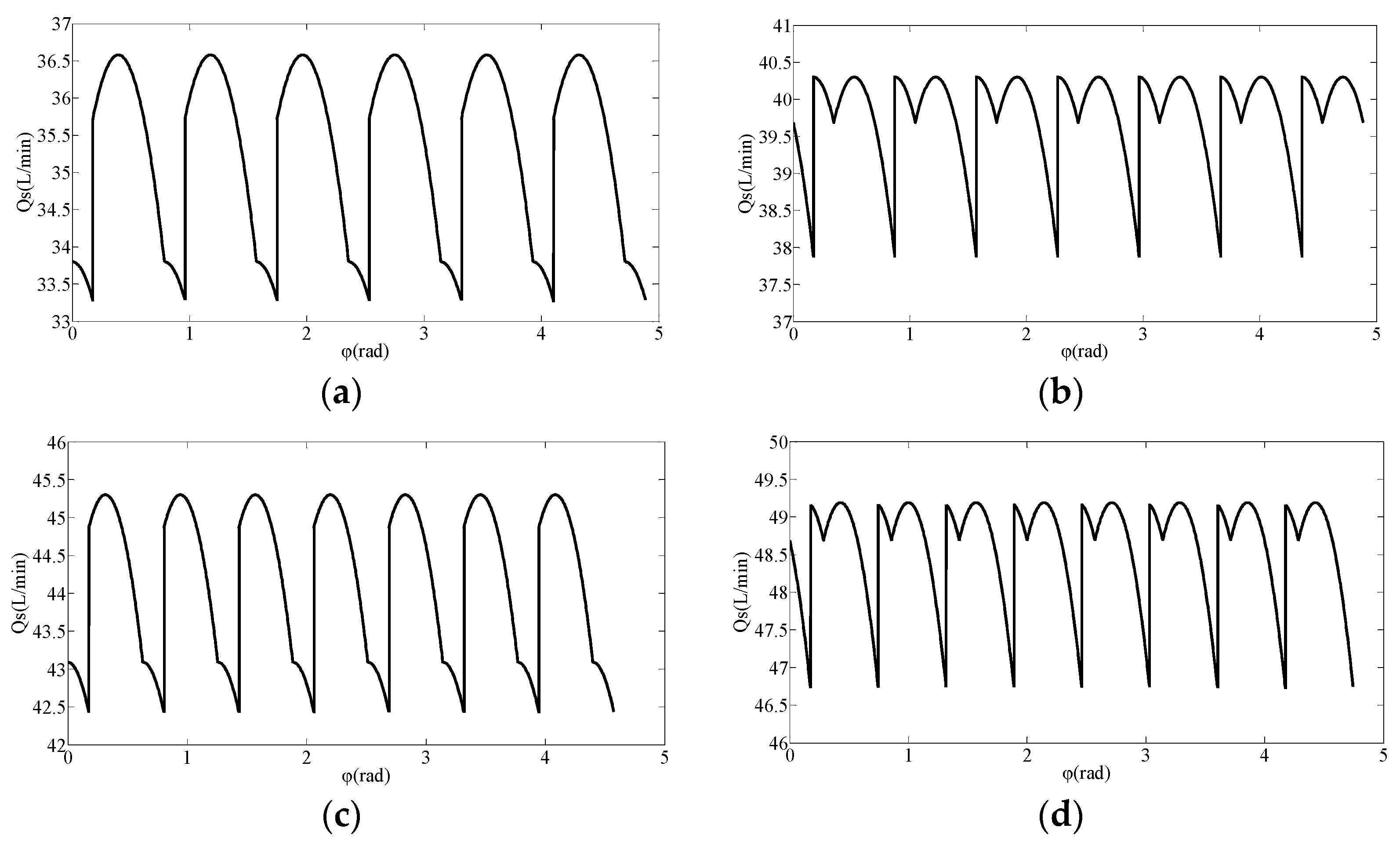
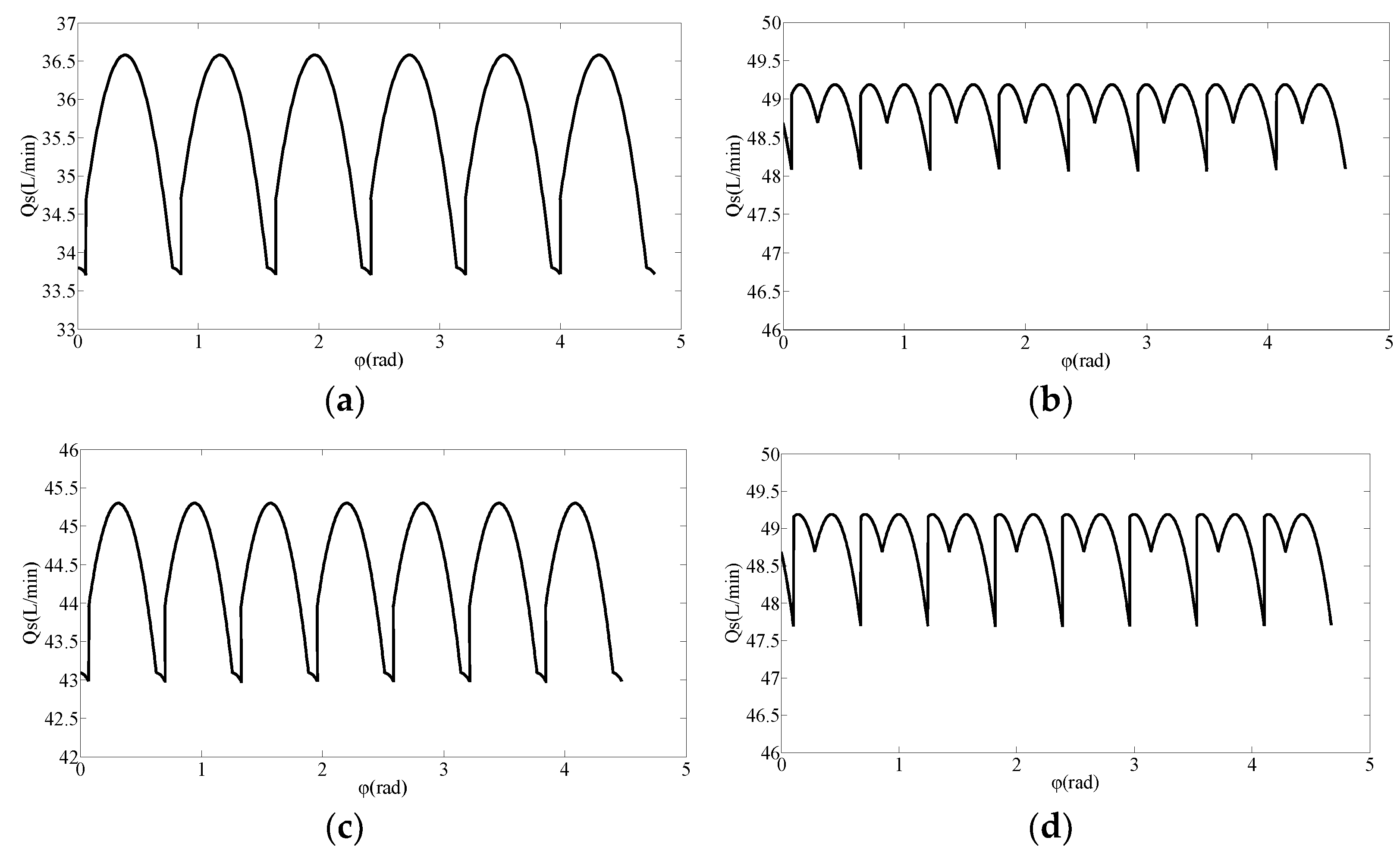
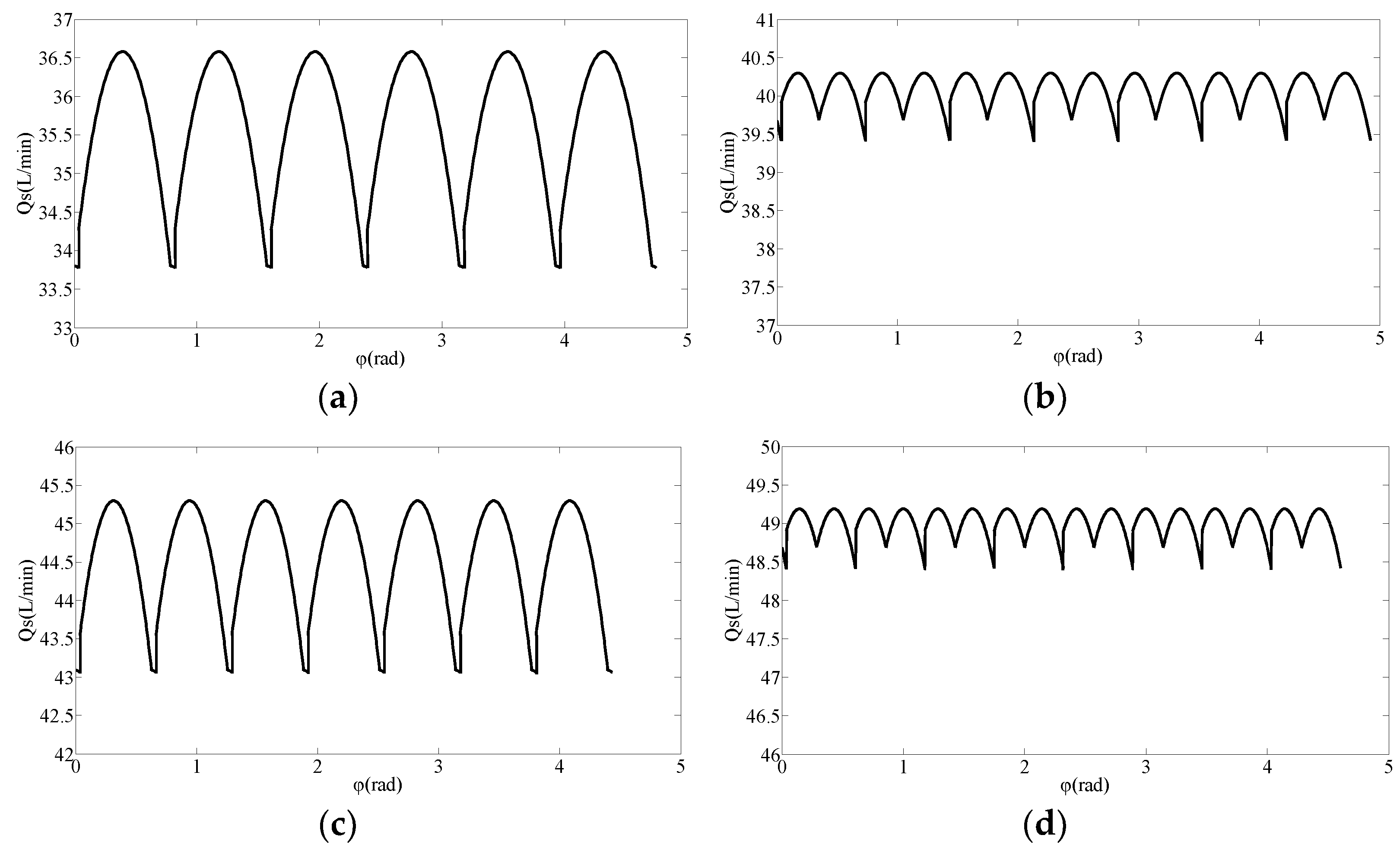
Given that the dead angles of the pre-boost and relief of the symmetrical deflection port plate are equal to the top, Δφ is used, which is called a closed dead angle for short. Δφ/2 = φ 0 = 6° is often used in engineering. Δφ/2=φ0=1~6°is taken during simulation to obtain six different flow distribution boundary conditions. Take the prime mover speed n = 1500 r/min, plunger diameter d = 17 mm and swashplate inclination γ = 12.5°, h0 = 0.005 mm, μ = 0.04025 Pa.s, l0 = 16.5 mm, h2 = 0.01 mm, r3 = 19.9 mm, r4 = 24.8 mm, r5 = 32.2 mm, r6 = 41.8 mm, α = 33.32°, h1 = 0.002 mm, r1 = 7.0 mm, r2 = 9.8 mm. When the number of plungers is 8, 9, 10 and 11, the actual output flow curve of plunger pump under constant working conditions is obtained by Matlab simulation, and the actual output flow curve of plunger pump under constant working conditions is obtained by Matlab simulation, as shown in Figure 6, Figure 7, Figure 8, Figure 9, Figure 10 and Figure 11.
From Figure 6, Figure 7, Figure 8, Figure 9, Figure 10 and Figure 11, it can be seen that when Δφ/2 = φ 0 decreases from 6° to 1°, the output flow curves of odd (9,11) and even (8,10) plunger pumps become more and more regular, the minimum value of pump output flow gradually increases, the flow pulsation decreases significantly and the output flow pulsation of the odd pump decreases faster than that of the even pump. Under the same port plate structure, with the decrease of the dead angle and the mismatch angle, the output flow pulsation difference of adjacent odd and even piston pumps increases significantly, but the difference is very small.
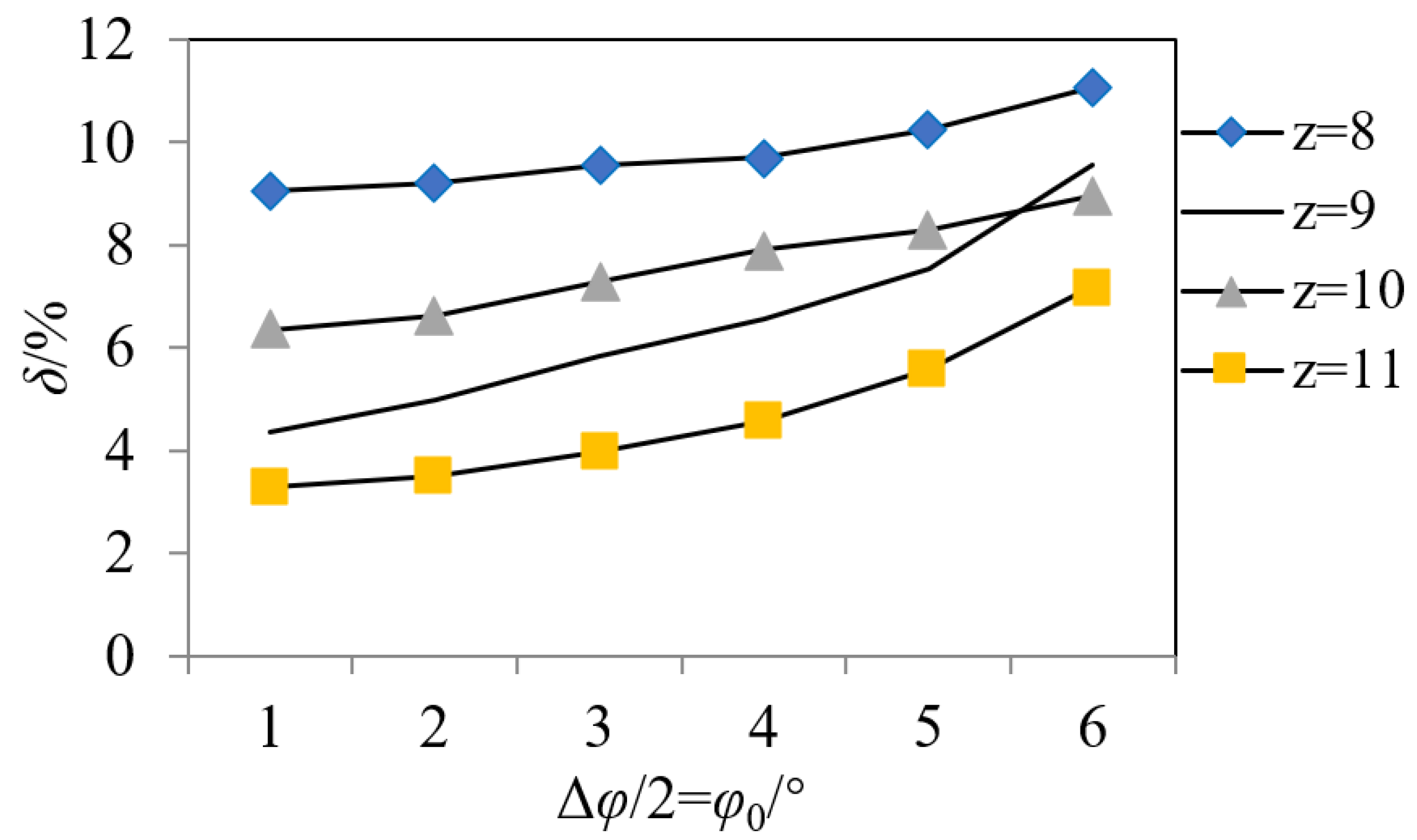
From Figure 6, Figure 7, Figure 8, Figure 9, Figure 10 and Figure 11, the variation curves of output flow pulsation rate of 8~11-piston pumps under six flow distribution boundary conditions can be obtained, as shown in Figure 12.
(1)
Δφ/2 = φ 0 = 6°, δz = 11 < δz = 10 < δz = 9 < δz = 8, that is, the larger the number of plungers, the smaller the pump output flow pulsation rate. The flow pulsation rate values are greater than the theoretical instantaneous flow pulsation rate, but the regularity is consistent with it. However, when Δφ/2 = φ 0 = 1~5°, δz = 11 < δz = 9 < δz = 10 < δz = 8, that is, the output flow pulsation of odd pump is obviously less than that of even pump.
(2)
When Δφ/2 = φ 0 decreases from 6° to 1°, the output flow curves of 8~11-piston pumps become more and more regular, the flow pulsation rate decreases gradually, the flow pulsation of odd number pump decreases faster than that of even number pump and the gap between them becomes larger and larger.
(3)
When Δφ/2 = φ 0 = 1°, the flow pulsation rate of 8~11-plunger pumps reaches the minimum value, which is close to the theoretical value. When Δφ/2 = φ 0 = 3°, the fluctuation of the difference of the pump flow pulsation rate of the number of adjacent plungers is the smallest. When Δφ/2 = φ 0 = 5~6°, the flow pulsation rates of 9- and 10-plunger pumps are very close. Under this port plate structure, the number of plungers is designed as 9 or 10, which breaks the convention that odd piston pumps are better than even piston pumps.

4. System Modeling and Simulation Analysis of Axial Piston Pump

4.1. Modeling and Correctness Verification

Considering factors such as oil leakage, flow distribution process and oil compressibility, the overall simulation model of a nine-plunger pump is built, as shown in Figure 13. After completing the model building and sub-model matching, set the parameters of the whole model in the parameter mode. The main simulation parameters are shown in Table 2.
The adjacent included angle of each plunger of a nine-plunger pump is 40°. According to its working characteristics, the first plunger moves from the minimum extension position and starts the oil absorption process within 0~180°. The angle offset of the oil absorption cycle signal switch is set to 0°, the second is 1 × 360°/z, the third is 2 × 360°/z, to the ninth plunger in turn. The signal of the oil drain switch lags 180° accordingly.
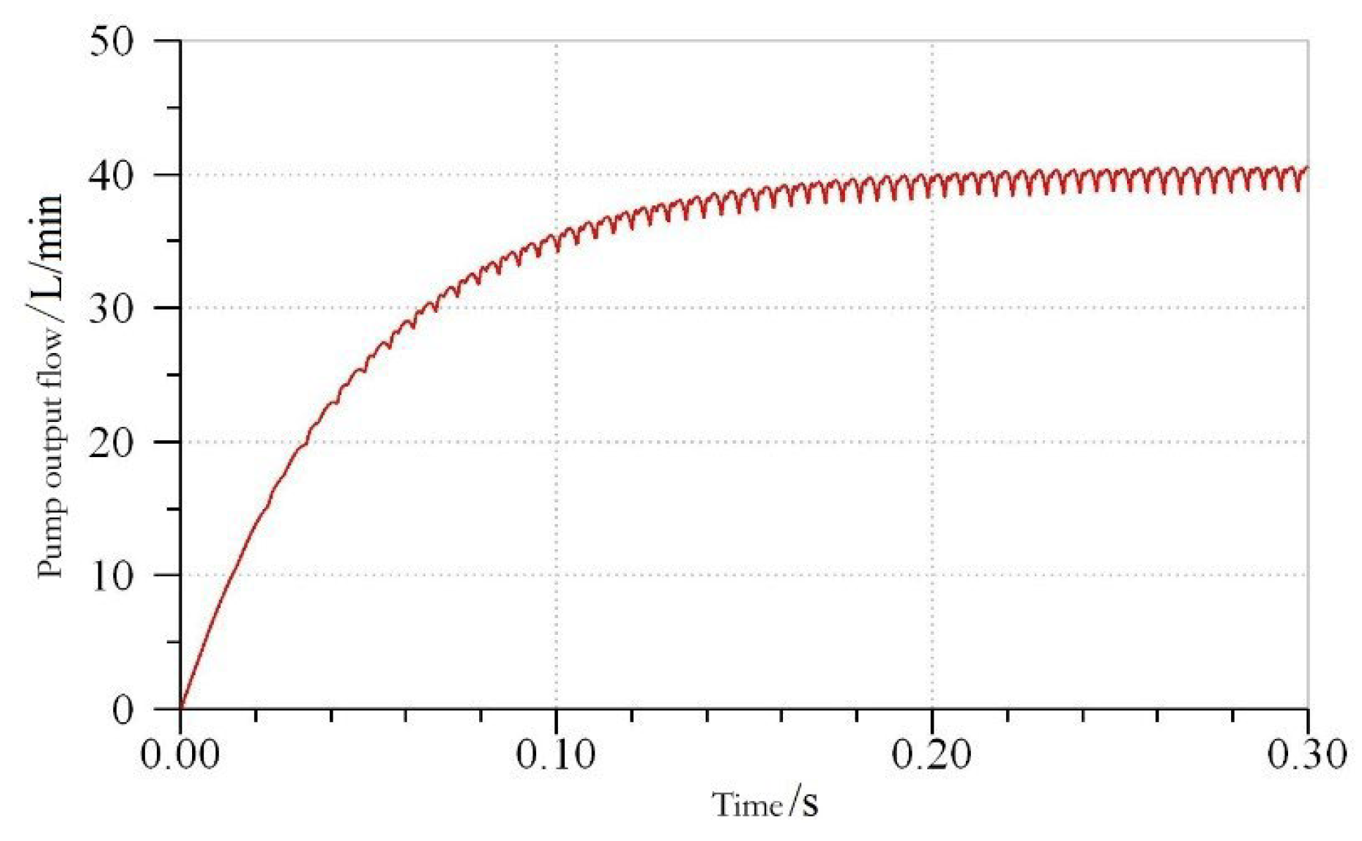
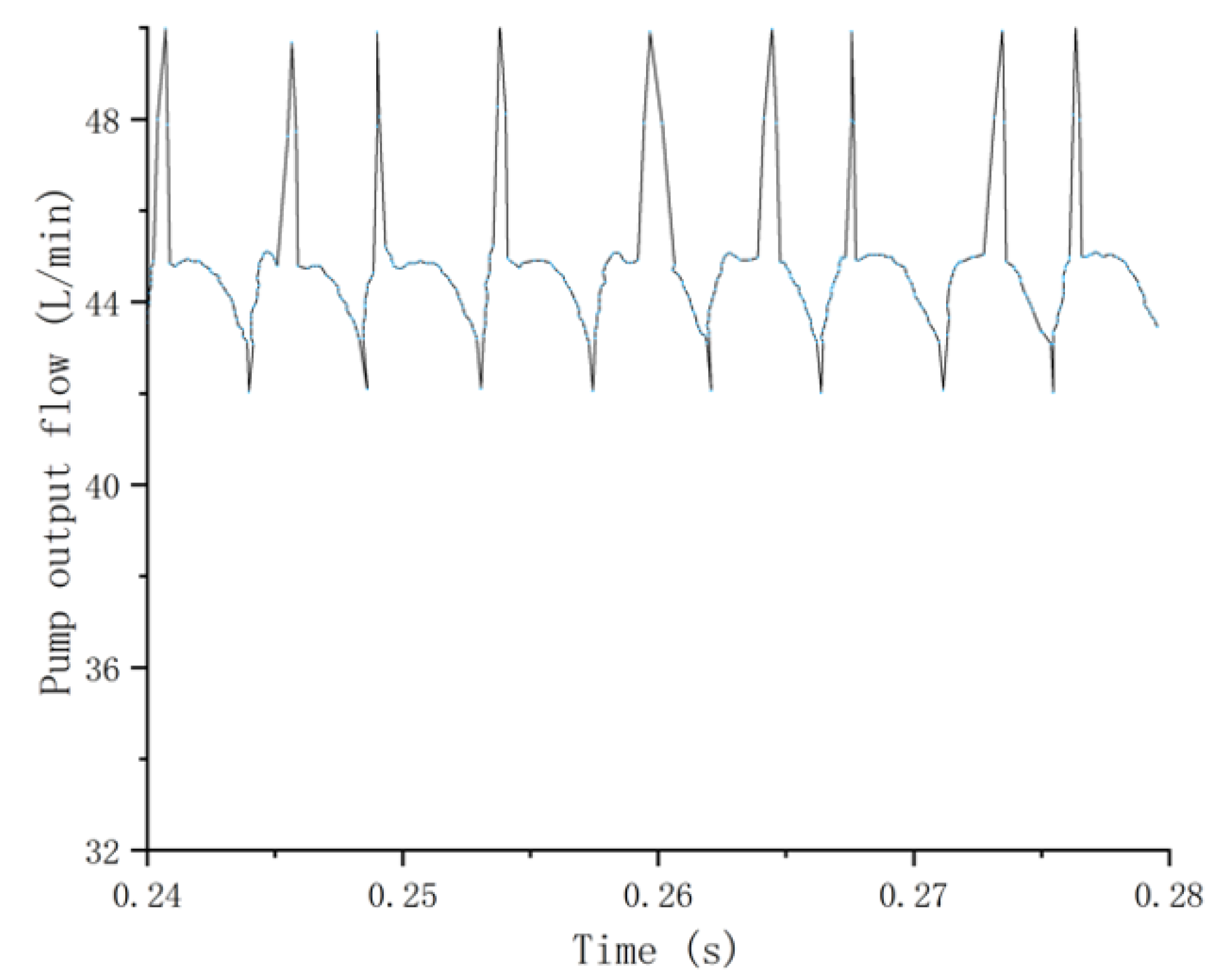
For the A10VNO axial piston pump, its rated pressure is 30 MPa. Therefore, in this paper, 46# anti-wear hydraulic oil, which is suitable for the working pressure and temperature of the plunger pump studied in this paper, is selected, with hydraulic oil density of 875 Kg/ m 3 , dynamic viscosity of 40.25 cP and bulk modulus of elasticity of 1700 MPa. Continuous commissioning and operation allows us to reasonably configure parameters and set the simulation time to 0.3 s to obtain the pump output flow, as shown in Figure 14.
It can be seen from Figure 14 that the pump output flow reaches a steady state at about 0.22 s, the maximum value remains at about 40.32 L/min and the minimum value is stable at about 38.64 L/min, which is more or less consistent with the data in Figure 9, which verifies the accuracy of the established simulation model.

4.2. Simulation Analysis of Influence of Port Plate Structure on Output Flow Pulsation of Axial Piston Pump

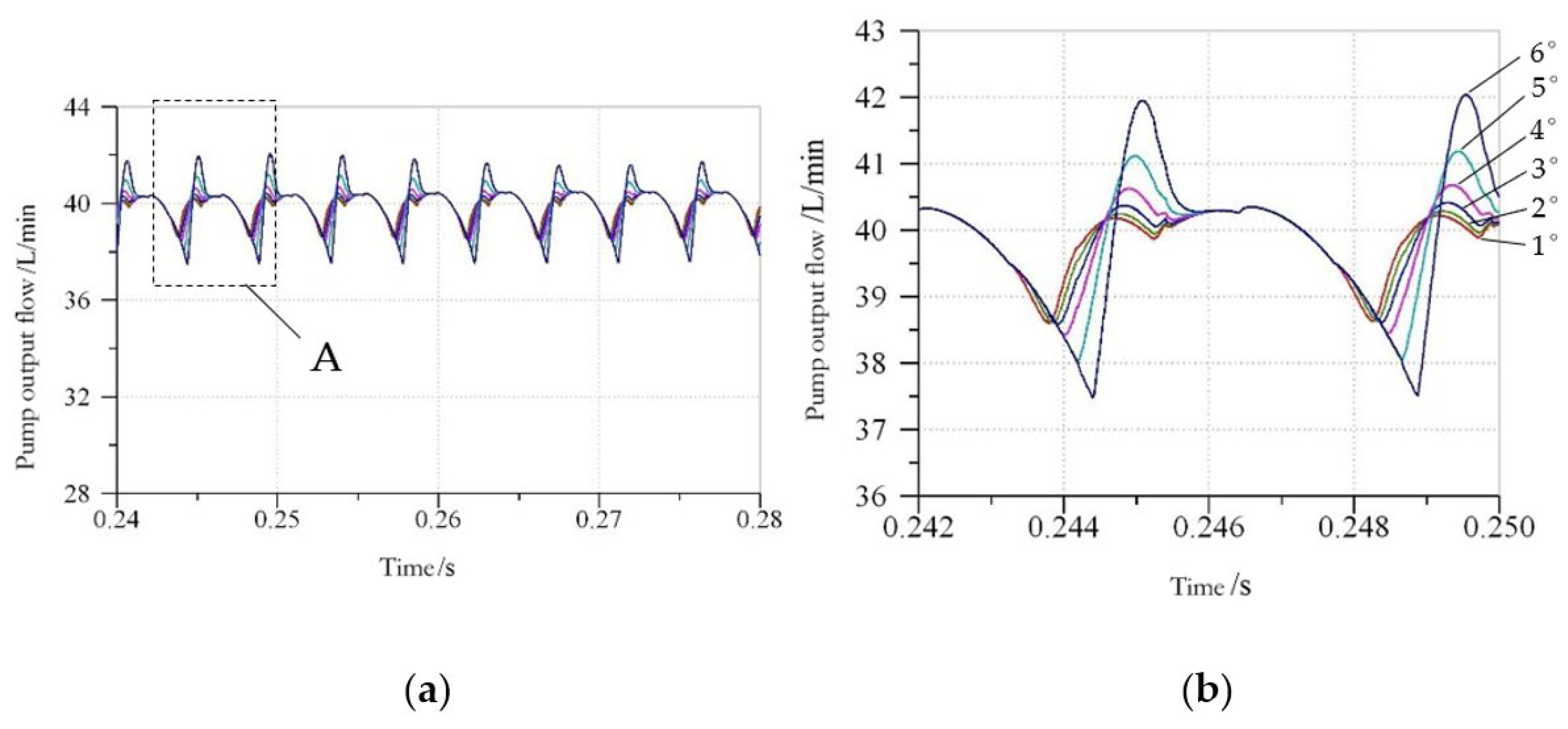
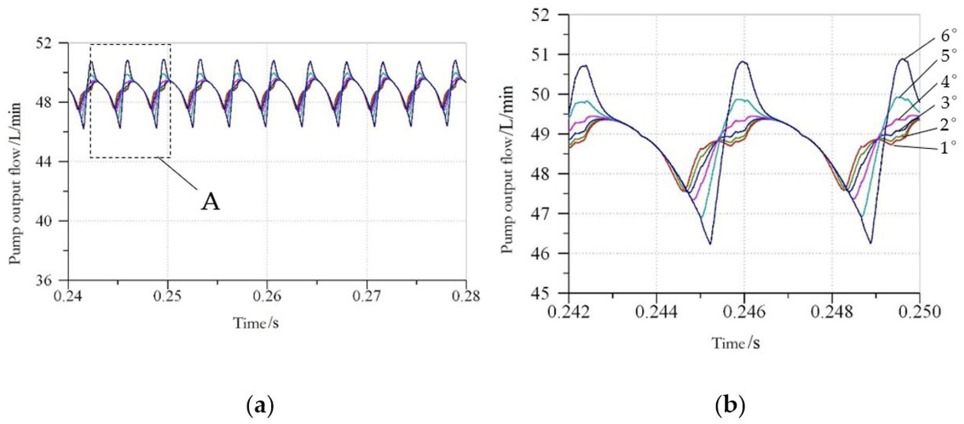
Using AMESim simulation platform, simulation models of the axial piston pump with 8–11 pistons considering the flow distribution process, friction, volume effect and other factors in steady state are established. The closed dead angle and mismatch angle of port plate are taken as Δφ/2 = φ 0 = 1~6°, set corresponding to six different flow distribution and overflow area curves in the AMESim simulation platform. Take the prime mover speed as n = 1500 r/min, plunger diameter d = 17 mm and swashplate inclination angle γ = 12.5°; simulate and analyze the piston pumps with 8, 9, 10 and 11 plungers, respectively; and obtain the output flow curves of 8~11 piston pumps under six flow distribution boundary conditions, as shown in Figure 15, Figure 16, Figure 17 and Figure 18.
It can be seen from Figure 15, Figure 16, Figure 17 and Figure 18 that as the mismatch angle increases from 1° to 6°, the output flow peak, rising speed and flow pulsation of odd (9, 11) and even (8, 10) plunger pumps increase, and the peak sharp angle becomes more and more obvious. The variation curve of flow pulsation rate of the pump under six flow distribution boundary conditions when the number of plungers is 8~11 is obtained, as shown in Figure 19.
Given that factors such as oil compressibility [30], friction and volume effect are considered in the simulation process, the simulation value in Figure 19 is larger than the theoretical value in Figure 12. It can be seen from Figure 19 that the overall change trend diagram of output flow pulsation rate of odd and even piston pumps under six kinds of flow distribution boundary conditions is consistent with the theoretical research, which verifies the correctness of analyzing the influence of the port plate structure on the output flow pulsation of the axial piston pump in the simulation.
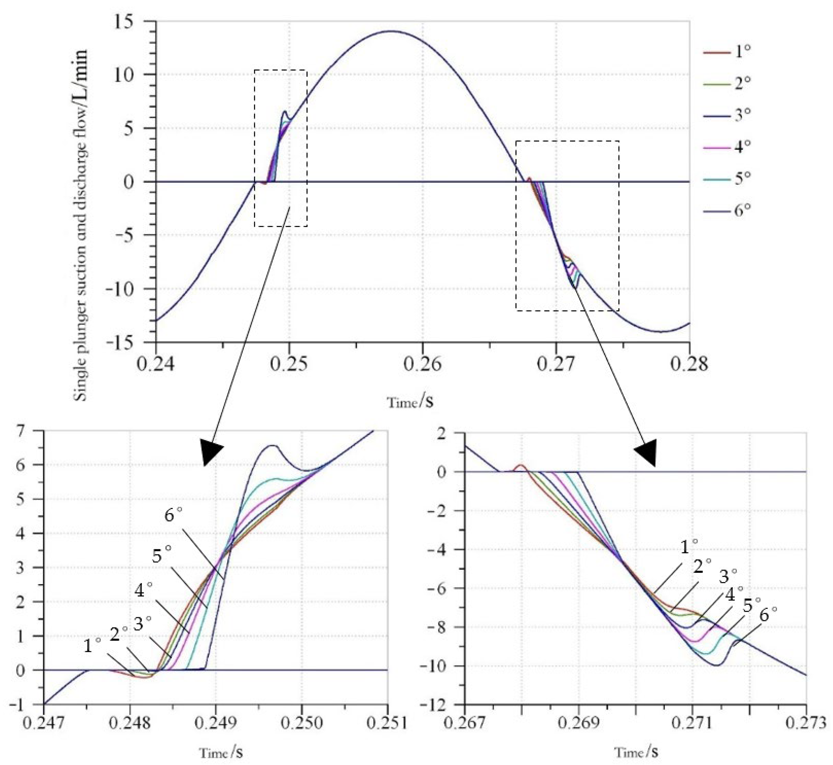
Figure 20 shows the change curve of oil suction and discharge flow of a single plunger under six flow distribution boundary conditions. It can be seen from the curve that a certain flow backflow occurs when a single plunger is switched in the high- and low- pressure areas. With the increase of the dead angle and the mismatch angle, the degree of flow backflow decreases. In the pre-boost stage, when the mismatch angle is greater than 3°, there is almost no flow backflow. In the pre-relief stage, when the mismatch angle is greater than 2°, the flow backflow is almost zero and the pressure can achieve a smooth transition, but when the plunger just enters the oil absorption area or oil discharge area, the flow overshoot occurs. With the increase of the dead angle and mismatch angle, the flow rises faster and faster, and the degree of flow overshoot increases, which will cause a certain pressure impact. When the mismatch angle is 6°, the flow overshoot is the most significant.
The theoretical and simulation analyses of the output flow pulsation of 8~11 piston pump show that when the closed dead angle and mismatch angle are reduced, the output flow pulsation of 8~11 piston pump is significantly reduced. From this point of view, the smaller the closed dead angle and mismatch angle are set, the more conducive they are to reducing the flow pulsation. However, if the settings of the dead angle and mismatch angle are too small, the process of pre-pressure rise and pre-pressure relief is reduced, and the time of pressure rise and fall is insufficient, which is not conducive to the stable transition of pressure. If the dead angle and mismatch angle are too large, there is a certain flow fluctuation when just entering the oil suction and drainage areas, resulting in a certain pressure impact. Therefore, it is reasonable to take 3~5° for the mismatch angle and 6~10° for the dead angle. Moreover, under this port plate structure, the difference of output flow pulsation between odd and even piston pumps is very small, so it is appropriate to adopt odd or adjacent even numbers for the number of pistons, breaking the convention that an odd pump is better than an even pump.

5. Experimental Verification

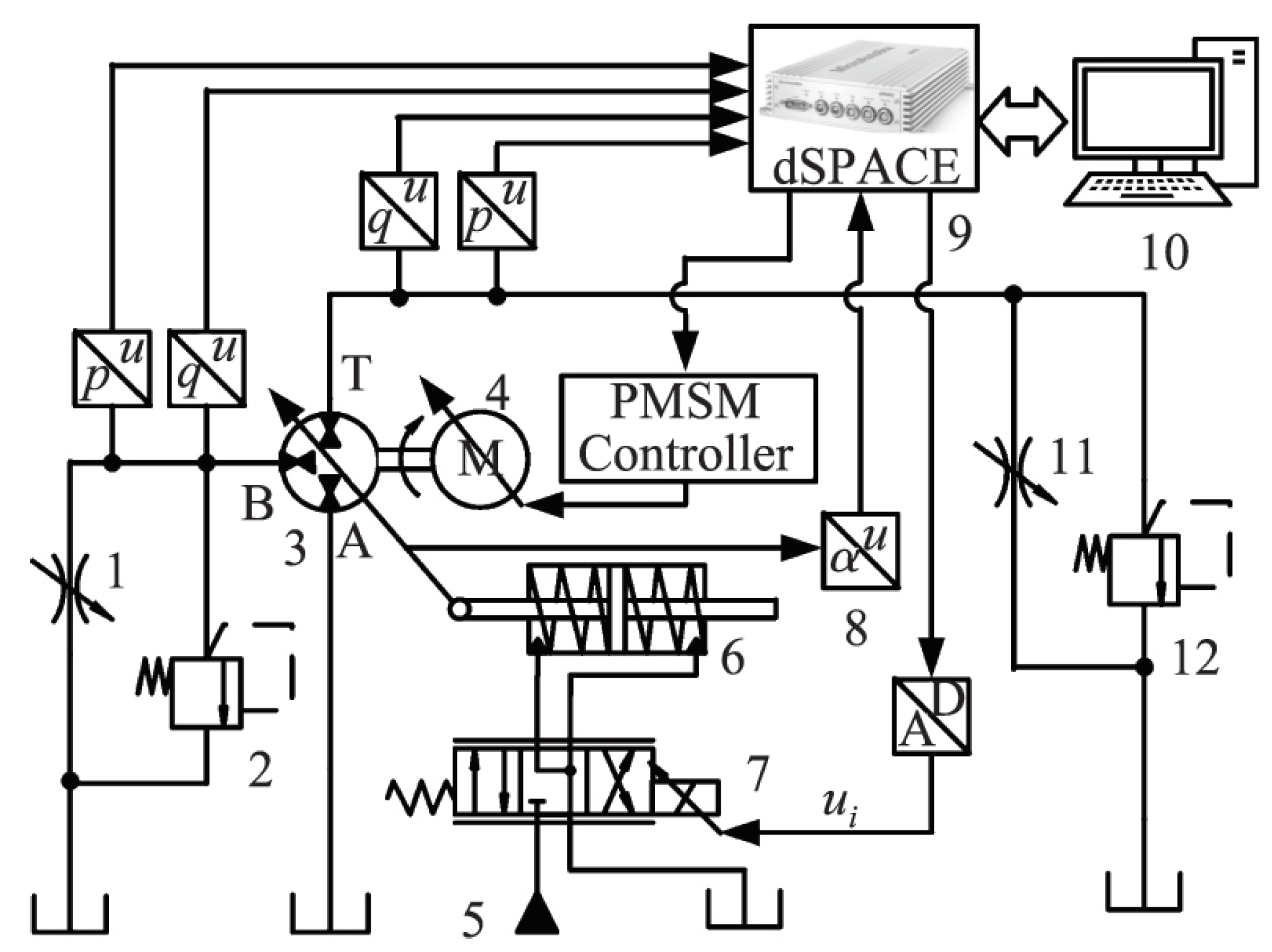
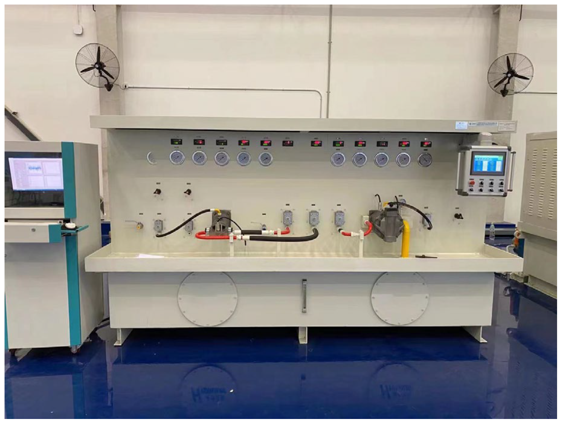
Based on A10VNO axial 9-piston pump, a 10-piston pump prototype was developed to test its flow pulsation characteristics. The shell size of the prototype is 183 mm × 144 mm × 156 mm and made of cast iron. The prototype has 10 plungers with a diameter of 17 mm. The physical structure is shown in Figure 21a, and the disassembly drawing is shown in Figure 21b. The flow pulsation characteristics of the 9-piston pump and 10-piston pump were tested. The test schematic diagram is shown in Figure 22 and the test bench is shown in Figure 23. The axial piston pump is composed of pump body 3, variable cylinder 6, servo proportional valve 7, angular displacement sensor 8 and controller 9. The motor 4 drives the pump body, the pressure at the oil discharge port is set through throttle valve 1 and throttle valve 11, and overflow valve 2 and overflow valve 12 are used as safety valves.
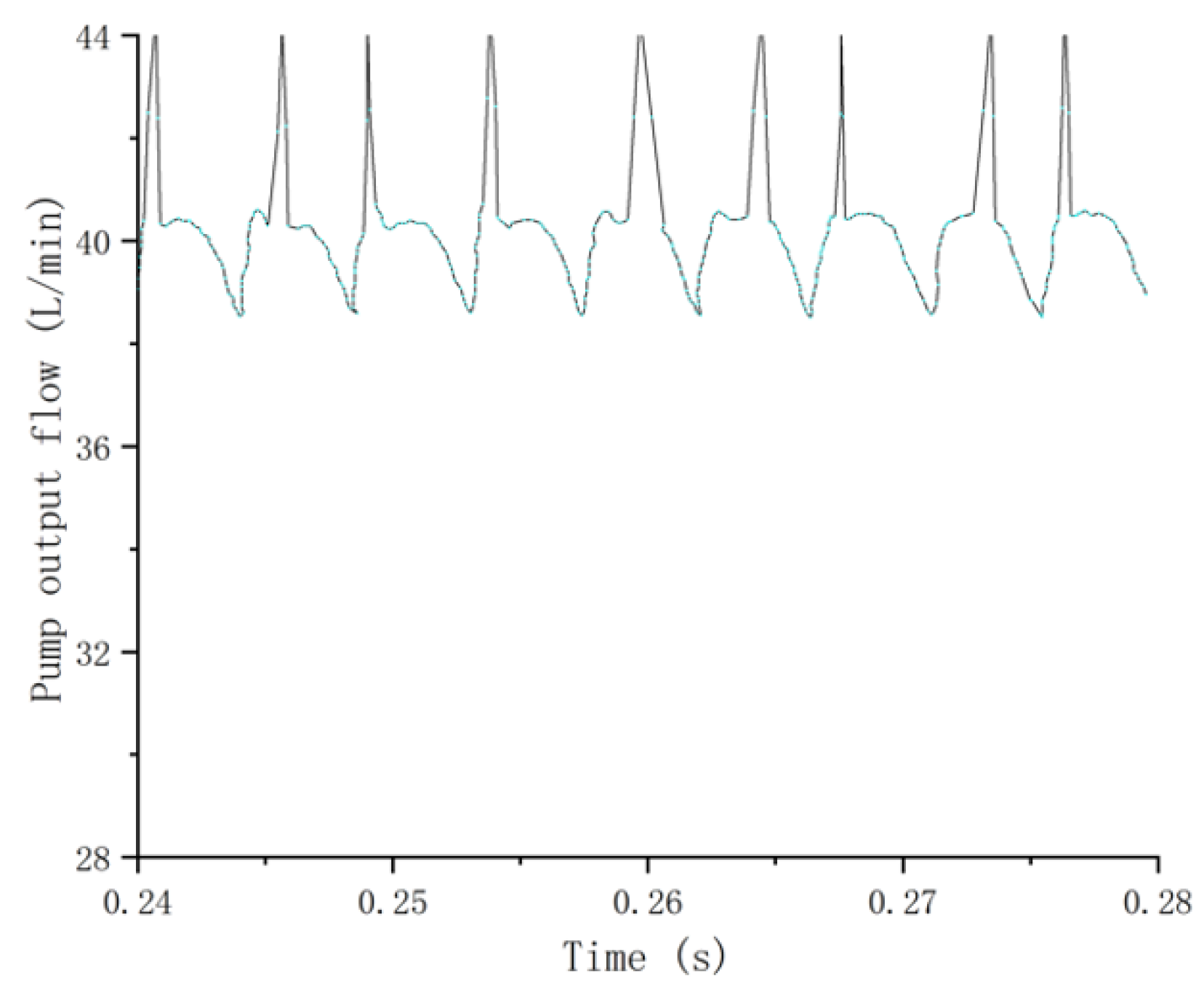
The pump speed was set to 1500 r/min and the inclined angle of swashplate to 12.5°, and the results of 9-piston pump and 10-piston pump experimental flow pulsation curves in Δφ/2 = φ 0 = 4° were obtained, which are shown in Figure 24 and Figure 25. The simulation and experimental values of the flow pulsation of the piston pump were calculated, as shown in Table 3. The pump outlet flow pulsation obtained from the test was more intense, and the difference between the maximum flow and the minimum flow was relatively large, because in the actual operation of the plunger pump, the flow pulsation will be affected by other factors, such as leakage pulsation, geometric pulsation and elastic pulsation, which will make the flow pulsation of the plunger pump larger than that in the simulation. The simulation data are in good agreement with the experimental data. It is verified that when the mismatch angle is 3~5° and the dead angle is 6~10°, the difference of output flow pulsation between odd and even piston pumps is very small.

6. Conclusions

(1)
Without considering leakage and flow distribution, the output flow pulsation rate of an odd pump is obviously lower than that of an even pump. With the increase of the number of plungers, the pump output flow pulsation rate decreases. The larger the number of plungers, the slower the decreasing trend of flow pulsation.
(2)
The influence of the port plate structure on pump output flow pulsation under different flow distribution conditions was studied. It is more reasonable when the mismatching angle of the valve plate is 3~5° and the dead angle is 6~10°. At this time, the difference between the output flow pulsation of odd and even piston pumps is very small, and the odd or adjacent even number of pistons is appropriate. In the hydraulic pump hydraulic motor system, when the hydraulic pump is used as a hydraulic motor under the condition of power recovery, the odd number or adjacent even number of hydraulic motors are appropriate.
(3)
Through the comparison of the prototype pump bench test and simulation data, the correctness of the simulation conclusion was verified, which provides a reference for the design and improvement of the piston pump.

Author Contributions

Methodology, R.L.; writing—review and editing, J.L.; investigation, J.L.; resources, X.D.; data curation, J.L.; writing—original draft preparation, J.L.; supervision, Q.L. All authors have read and agreed to the published version of the manuscript.

Funding

Funding was obtained from Key R&D plan of Shandong Province, China, grant number 2020CXGC010806; Key R&D plan of Shandong Province, China, grant number 2021CXGC010813; Key R&D plan of Shandong Province, China, grant number 2020CXGC011005; Innovation team project of colleges and universities of Jinan science and Technology Bureau, Shandong Province, China, grant number 2020GXRC042.

Acknowledgments

I would like to thank my tutor, Ruichuan Li, for all his support and guidance. I would like to thank my colleagues for their care and help in my daily work.

Conflicts of Interest

The authors declare no conflict of interest.

References

  1. Pan, Y.; Li, Y.B. Valve Plate Improvement and Flow Ripple Characteristic Analysis for Double Compound Axial Piston Pump. Trans. Chin. Soc. Agric. Mach. 2016, 47, 391–398. [Google Scholar]
  2. Hu, M.; Xu, N. Modelling and Analysis of Dynamics Characteristics of Piston-slipper Group of Axial Piston Pump. Trans. Chin. Soc. Agric. Mach. 2016, 47, 373–380. [Google Scholar]
  3. Zhang, X.G.; Yan, Z.; Quan, L. Theoretical Analysis and Experiment on Flow Allocation Characteristics of Dual Discharging Axial Piston Pump. Trans. Chin. Soc. Agric. Mach. 2017, 48, 373–380. [Google Scholar]
  4. Zhang, Z.P. Design and Research of 55 mL/R Eleven Plunger Swashplate Axial Piston Pump. Master’s Thesis, Southwest Jiao Tong University, Chengdu, China, 2009. [Google Scholar]
  5. Yuan, H. Structural Optimization Design of Key Parts of Swashplate Axial Piston Pump. Master’s Thesis, Hefei Polytechnic University, Hefei, China, 2015. [Google Scholar]
  6. Wang, H.Y.; Wei, X.Y. Simulation Study on the Flow Pulsation Characteristics of Axial Piston Pump. Mach. Tool Hydraul. 2014, 42, 144–148. [Google Scholar]
  7. Ye, M. Theoretical analysis of flow pulsation of axial piston pump. Trans. Chin. Soc. Agric. Mach. 1990, 19, 41–47. [Google Scholar]
  8. Na, Y.Q.; Yin, W.B.; Na, C.L. Theretical Analysis of Transit Flow Through Axial Piston Pumps. J. Lanzhou Univ. Technol. 2004, 30, 56–59. [Google Scholar]
  9. Liu, C.J.; Xu, X.L. Simulation analysis of actual flow in axial piston pump. Mach. Tool Hydraul. 1999, 3, 66–67. [Google Scholar]
  10. Yan, Y.Q.; Shi, Z.Q.; Zheng, L. Analysis of Influence Factors for Axial Piston Hydraulic Pump Flow Fluctuation Based on AMESim. Chin. Hydraul. Pnenumatics 2014, 2, 104–108. [Google Scholar]
  11. Zhang, R.; Liu, H.L.; Ke, J. Characteristics Simulation of Swashplate Axial Piston Pump Based on AMESim. Mach. Tool Hydraul. 2012, 40, 118–120. [Google Scholar]
  12. Harrisona, M.; Edge, K.A. Proceedings of the Institution of Mechanical Engineers; Institution of Mechanical Engineers: London, UK, 2000; Volume 214, pp. 53–64. [Google Scholar]
  13. Weddfelt, K.G.; Pettersson, M.E.; Palmberg, J. Methods of Reducing Flow Ripple from Fluid Power Piston Pumps-an Experimental Approach. Phys. Status Solidi Appl. Res. 1991, 73, 71–79. [Google Scholar]
  14. Liu, Z.F.; Yuan, H.; Cheng, H.B. Method for Determining Best Piston Numbers of a Swash Plate Axial Piston Pump. China Mech. Eng. 2015, 26, 237–242. [Google Scholar]
  15. Bergada, J.M.; Kumar, S.; Davies, D.L.; Watton, J. A complete analysis of axial piston pump leakage and output flow ripples. Appl. Math. Model. 2012, 36, 1731–1751. [Google Scholar] [CrossRef]
  16. Bergada, J.M.; Watton, J.; Haynes, J.M.; Davies, D.L. The hydrostatic/hydrodynamic behaviour of an axial piston pump slipper with multiple lands. Meccanica 2010, 45, 585–602. [Google Scholar] [CrossRef] [Green Version]
  17. Bergada, J.M.; Davies, D.L.; Kumar, S.; Watton, J. The effect of oil pressure and temperature on barrel film thickness and barrel dynamics of an axial piston pump. Meccanica 2012, 47, 639–654. [Google Scholar] [CrossRef]
  18. Zhu, H.; Bo, G.; Zhou, Y.B. Pump Selection and Performance Prediction for the Technical Innovation of an Axial-Flow Pump Station. Math. Probl. Eng. 2018, 2018, 6543109. [Google Scholar] [CrossRef]
  19. Zhang, T.X.; Zhang, N. Vibration Modes and the Dynamic Behaviour of a Hydraulic Plunger Pump. Shock. Vib. 2016, 2016, 9679542. [Google Scholar] [CrossRef] [Green Version]
  20. Ji, D.T.; Lu, W.G.; Lu, L.G. Comparison of Saddle-Shaped Region of Head-Flow Curve between Axial-Flow Pump and Its Corresponding Axial-Flow Pump Device. Shock. Vib. 2021, 2021, 9481822. [Google Scholar] [CrossRef]
  21. Lasaar, R. The influence of the microscopic and macroscopic gap geometry on the energy dissipation in the lubricating gaps of displacement machines. In Proceedings of the 1st FPNI-PhD Symposium, Hamburg, Germany, 20–22 September 2000; Volume 9, pp. 101–116. [Google Scholar]
  22. Lasaar, R.; Ivantysynova, M. Advanced gap design-basis for innovative displacement machines. In Proceedings of the 3rd International Fluid Power Conference, Aachen, Germany, 5–6 March 2002; Volume 2, pp. 215–230. [Google Scholar]
  23. Olems, L. Investigations of the temperature behaviour of the piston cylinder assembly in axial piston pumps. Int. J. Fluid Power 2000, 1, 27–39. [Google Scholar] [CrossRef]
  24. Park, S.H.; Lee, J.M.; Kim, J.S. Robust control of the pressure in a control-cylinder with direct drive valve for the variable displacement axial piston pump. Proc. Inst. Mech. Eng. Part I J. Syst. Control Eng. 2009, 223, 455–465. [Google Scholar] [CrossRef]
  25. Zhang, X.J.; Chen, Y.H.; Zhou, Z.J. Influence of Axial Piston Pump Parameters to Flow and Pressure Pulsation. Mach. Tool Hydraul. 2018, 46, 125–129. [Google Scholar]
  26. Zhang, J.; Liu, B.L.; Lv, R.Q.; Yang, Q.F.; Dai, Q.M. Study on Oil Film Characteristics of Piston-Cylinder Pair of Ultra-High Pressure Axial Piston Pump. Processes 2020, 8, 68. [Google Scholar] [CrossRef] [Green Version]
  27. Deng, H.S.; Wang, Q.C.; Dai, P.; Yang, Y.K. Study on Leaking Characteristics of Port Plate Pair in Primary Three-Row Axial Piston Pump/Motor. Math. Probl. Eng. 2018, 2018, 7395727. [Google Scholar] [CrossRef] [Green Version]
  28. Hong, H.C.; Zhao, C.X.; Zhang, B.; Bai, D.P.; Yang, H.Y. Flow Ripple Reduction of Axial-Piston Pump by Structure Optimizing of Outlet Triangular Damping Groove. Processes 2020, 8, 1664. [Google Scholar] [CrossRef]
  29. Huang, Y.; Ruan, J.; Zhang, C.C.; Ding, C.; Li, S. Research on the Mechanical Efficiency of High-Speed 2D Piston Pumps. Processes 2020, 8, 853. [Google Scholar] [CrossRef]
  30. Gao, Y.J.; Gu, L.C.; Jiao, L.F. Effects of Oil Properties on Flow Pulsation of Axial Piston Pumps by Simulation Analysis. China Mech. Eng. 2017, 28, 1333–1338. [Google Scholar]
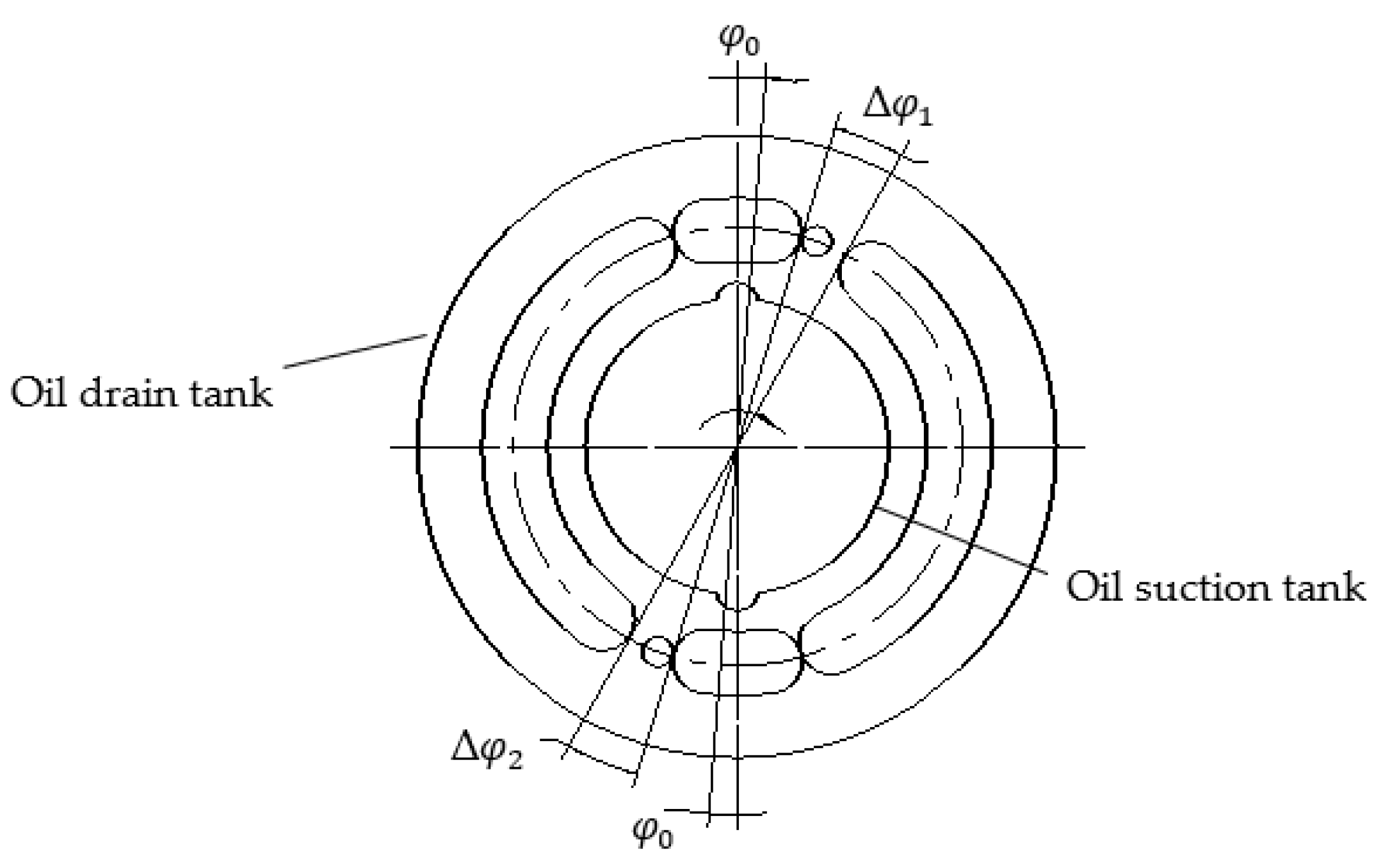
Figure 1. The typical symmetric port plate structure.
Processes 10 01077 g001
Figure 2. Output flow pulsation curve of piston pump with odd piston (z = 5, 7, 9, 11).
Processes 10 01077 g002
Figure 3. Output flow pulsation curve of piston pump with even number of pistons (z = 6, 8, 10, 12).
Processes 10 01077 g003
Figure 4. The piston and cylinder bore.
Processes 10 01077 g004
Figure 5. The swash plate and slipper.
Processes 10 01077 g005
Figure 6. Actual output flow rate of piston pumps with 8~11 pistons for Δφ/2 = φ0 = 6°. (a) output flow of 8-plunger pump; (b) output flow of 9-plunger pump; (c) output flow of 10-plunger pump; (d) output flow of 11-plunger pump.
Processes 10 01077 g006
Figure 7. Actual output flow rate of piston pumps with 8~11 pistons for Δφ/2 = φ0 = 5°. (a) output flow of 8-plunger pump; (b) output flow of 9-plunger pump; (c) output flow of 10-plunger pump; (d) output flow of 11-plunger pump.
Processes 10 01077 g007
Figure 8. Actual output flow rate of piston pumps with 8~11 pistons for Δφ/2 = φ0 = 4°. (a) output flow of 8-plunger pump; (b) output flow of 9-plunger pump; (c) output flow of 10-plunger pump; (d) output flow of 11-plunger pump.
Processes 10 01077 g008aProcesses 10 01077 g008b
Figure 9. Actual output flow rate of piston pumps with 8~11 pistons for Δφ/2 = φ0 = 3°. (a) output flow of 8-plunger pump; (b) output flow of 9-plunger pump; (c) output flow of 10-plunger pump; (d) output flow of 11-plunger pump.
Processes 10 01077 g009
Figure 10. Actual output flow rate of piston pumps with 8~11 pistons for Δφ/2 = φ0 = 2°. (a) output flow of 8-plunger pump; (b) output flow of 9-plunger pump; (c) output flow of 10-plunger pump; (d) output flow of 11-plunger pump.
Processes 10 01077 g010
Figure 11. Actual output flow rate of piston pumps with 8~11 pistons for Δφ/2 = φ0 = 1°. (a) output flow of 8-plunger pump; (b) output flow of 9-plunger pump; (c) output flow of 10-plunger pump; (d) output flow of 11-plunger pump.
Processes 10 01077 g011
Figure 12. Output flow pulsation rate curve of piston pumps with 8~11 pistons under 6 flow distribution boundary conditions.
Processes 10 01077 g012
Figure 13. Simulation model of an axial piston pump with 9 pistons.
Processes 10 01077 g013
Figure 14. Output flow rate of axial piston pump.
Processes 10 01077 g014
Figure 15. Actual output flow rate of piston pump with 8 pistons for Δφ/2 = φ 0 = 1~6°. (a) Pump output flow; (b) Pump output flow (enlarged view at A).
Processes 10 01077 g015
Figure 16. Actual output flow rate of piston pump with 9 pistons for Δφ/2 = φ 0 = 1~6°. (a) Pump output flow; (b) Pump output flow (enlarged view at A).
Processes 10 01077 g016
Figure 17. Actual output flow rate of piston pump with 10 pistons for Δφ/2 =   φ 0 = 1~6°. (a) Pump output flow; (b) Pump output flow (enlarged view at A).
Processes 10 01077 g017
Figure 18. Actual output flow rate of piston pump with 11 pistons for Δφ/2 = φ 0 = 1~6°. (a) Pump output flow; (b) Pump output flow (enlarged view at A).
Processes 10 01077 g018
Figure 19. The flow pulsation rate curve of piston pump with 8~11 pistons under 6 flow distribution boundary conditions.
Processes 10 01077 g019
Figure 20. The curve of inlet and outlet flow rate of single piston for Δφ/2 = φ0 = 1~6°.
Processes 10 01077 g020
Figure 21. 10-plunger pump prototype. (a) Physical structure; (b) Disassembly drawing.
Processes 10 01077 g021
Figure 22. Axial piston pump test system.
Processes 10 01077 g022
Figure 23. The experimental station.
Processes 10 01077 g023
Figure 24. Experimental diagram of a 9-piston plunger pump.
Processes 10 01077 g024
Figure 25. Experimental diagram of a 10-piston plunger pump.
Processes 10 01077 g025
Table 1. Output flow pulsation rates of axial piston pumps.
Z is an odd number57911Z is an even number681012
Pulsation rate δ1/%4.972.521.531.02Pulsation rate δ1/%14.037.664.973.45
Table 2. Main simulation parameters.
NameNumerical ValueUnit
Radius of plunger distribution circle29.7mm
Prime mover speed1500r/min
Plunger diameter17mm
Inclined plate12.5degree
Contact length between plunger and cylinder block34.6mm
Viscous damping coefficient5Nm (rev/min)
Coulomb friction torque loss3Nm
Static friction torque loss7Nm
Plunger pair fit clearance0.005mm
Shoe pair clearance0.002mm
Clearance of port pair0.01mm
Moment of inertia of cylinder block0.0016Kgmm2
Initial tank pressure2bar
Maximum opening diameter of oil drain throttle valve2.9mm
Maximum opening diameter of oil suction throttle valve4.3mm
Table 3. Flow pulsation.
NameSimulation ValueExperimental Value
9 plunger pump6.567.45
10 plunger pump7.918.65
Publisher’s Note: MDPI stays neutral with regard to jurisdictional claims in published maps and institutional affiliations.