Abstract
The study of the performance of dynamic hydraulic throttling under the condition of stable fluid is of great significance. The effect of a step change in pressure differences on the throttling performance of a hydraulic valve is studied. This paper studies the dynamic and static performance of a hydraulic-valve-outlet throttling-speed regulation system, builds a more accurate mathematical model, considers the linear factors of the flow of hydraulic-valve throttling, analyzes the influence of the step-load change in pressure difference on the stability of the hydraulic-valve movement speed, and constructs a nonlinear mathematical model of the speed-regulation system of the outlet throttling. A pressure sensor is used to measure the change in pressure overshoot, and the effect of a pressure-difference step change on the throttling performance of the hydraulic valve is studied under steady-fluid conditions. The theory is analyzed and verified by experiment, and the parameters of hydraulic components are modified using the dynamic-change rule of the hydraulic valve’s two-chamber pressure.
1. Introduction
As one of the main types of construction machinery, the loader has the advantages of flexibility, convenience, powerful function, and variety. It is an indispensable piece of equipment in mining, road traffic, national defense, and urban construction. The hydraulic system is one of the core systems of the loader; it can control all kinds of actions of the loader and plays a decisive role in the actual performance of the loader. With the development of the global industry, the application, field, and scope of hydraulic technology are expanding continuously. While the hydraulic system of a loader is developing towards high pressure, large flow, and high power, the problem of dynamic control of the quality stability of the system is becoming more and more serious due to external interference in the actual working process. Therefore, it is necessary to analyze and study the dynamic performance of the hydraulic system of a loader. Based on analysis of the working principle and experimental data of the actual hydraulic system of a loader, the relationship between the pressure and flow rate of the system in the working process is studied emphatically, and the dynamic-working characteristics of the system are understood and mastered so as to further improve and perfect the hydraulic system, improve the dynamic stability and response characteristics of the system, improve the working reliability, and adapt to the complex and changeable working environment. With the development of science and technology, using computer-simulation technology as a tool to study the dynamic characteristics of the actual hydraulic system is an important means of modern hydraulic-system development [1,2,3].
Computer simulation is the process of establishing a system model on a computer, analyzing and experimenting under environmental conditions (real or simulated), studying the various working conditions of the actual, physical system, and determining the best parameters [4,5]. This method is based on the actual hydraulic system to establish the simulation model, compare and analyze the experimental results with the simulation results, complete the simulation-model debugging, and study the dynamic performance of the entire hydraulic system by simulation analyses. This research method can shorten the debugging time of the hydraulic system or the design time of components; avoid loss caused by repeated experiments and processing; analyze, evaluate, and forecast the entire system involved; understand in advance existing problems in the dynamic characteristics of the system; and improve them so as to optimize the system, shorten the design cycle, and improve the stability of the system [6,7,8,9]. Das et al., discussed the simultaneous estimation of parameters in the two-dimensional, transient conduction–radiation, heat-transfer problem by using the lattice Boltzmann method and the inversion method of the finite-volume method combined with the genetic algorithm to estimate three parameters. In the direct method, the radiation information was calculated, and the energy equation was solved. This method can predict unknown parameters accurately, but it takes along period of time [10]. Kundu et al., studied the differential-transformation method of an exponential-fin thermal analysis under sensible latent heat, applied the differential-transformation method to analyze thermal performance, took the humidity ratio as a polynomial function, determined the surface temperature using regression analysis, calculated the mass-transfer process, and studied and discussed the influence of wet-surface and variable conductivity on temperature and fin efficiency. It was found that this method has different effects on the efficiency of different geometric exponential fins, which makes a certain contribution to the development of computer technology. However, it is difficult to define the error of this method [11]. Singla, R. K. et al., studied the application of the A domian-decomposition method and the inverse solution of variable thermal conductivity and heat-generating fin, used the ADM and the genetic algorithm to inversely predict the internal heat-generation conditions, and used the Newton–Rafson method to estimate the correlation constant representing the temperature of the fin tip. This study found that as long as there is accurate temperature data, the estimation of the unknown is unique. This study provides a reference for the measurement of the temperature field, but it is still incomplete [12]. Panda et al., used the homotopy analysis method to study the inverse solution of rectangular wet wings, to solve the conditions of an adiabatic convective-fin end boundary and used the genetic algorithm to estimate the relevant thermal-geometry parameters under a given temperature field. This study effectively controlled the closed solution of equations and boundary conditions and takes nonlinear effects into account. It can achieve the required heat-transfer task and the required reconstruction effect [13].
The hydraulic system is the foundation of a loader’s movement and automatic control. The dynamic performance of the loader’s hydraulic system directly determines the safety and stability of the entire machine. Therefore, it is necessary to use computer-simulation technology to study the dynamic characteristics of the loader’s hydraulic system. In the literature, the hydraulic-simulation software, EASY5, was used to establish the computer-simulation model of a certain type of the loader’s hydraulic system, and the initial setting of the simulation model was based on the parameters of each component of the actual hydraulic system [14,15,16,17].
The performance of the hydraulic-valve throttle was studied. Reference [18] was based on the method of fluid dynamics. The influence of the throttle valve’s opening on the oil-pressure field and velocity field was studied. The area with high pressure in the channel was located in the upper channel, and the area with low pressure was located in the lower channel. The pressure gradient of the orifice increased with the decrease in the opening of the orifice. The velocity region of the hydraulic low flow was mainly distributed at the bottom of the upstream groove, the top of the spool, and the corner of the valve chamber. With the decrease in the opening of the valve’s port, the flow velocity increased along an increase in the throttle and decreased gradually under the action of the cross-sectional area of the flow passage and under the resistance caused by the viscosity of the oil. There are three return zones located at the base of the upstream valve: at the top of the spool and at the corner of the valve chamber. The area of the return zone decreased with the decrease in the opening of the valve port. Therefore, the initial position of the cavitation was near the orifice of the throttle’s valve, and the downstream cavitation area was caused by free bubbles. With the decrease in the opening, the cavitation’s intensity increased and then decreased, and the cavitation area gradually expanded and decreased, which affected the throttling performance of the hydraulic valve. In reference [19], the orifice form and structure size of the throttle valve had a direct impact on the performance of the hydraulic-throttle valve. Therefore, the selection and design of the orifice structure is of great importance. Using the numerical-simulation method, the influence of the size of the secondary orifice on the cavitation fluency and flow rate of the hydraulic valve was studied. The results showed that there are four backflow zones at the corner of the upstream cavity of the two-stage hydraulic-throttle valve, near the wall of the middle cavity of the two-stage throttle valve, near the wall of the top of the spool, and downstream of the throttle’s port. With the change in the size of the hydraulic-valve port, the position of the return zone of the hydraulic valve did not change, but the area of the return zone easily changed. When the size of the orifice was fixed, the throttle valve had better cavitation resistance, but the performance of the throttle valve did not improve [20,21,22].
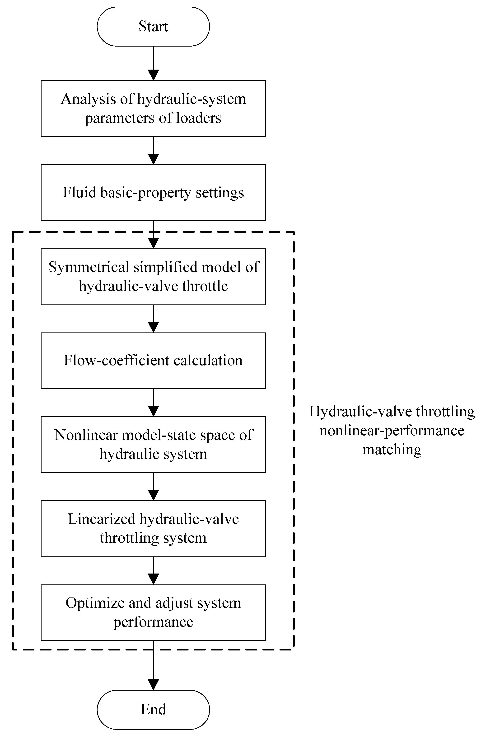
In order to improve throttling performances, cavitation fluency, and the flow rate of the hydraulic valve, a performance-matching optimization-design method for the loader’s hydraulic system based on a fluid-dynamics analysis is proposed in this paper. The research framework of this paper is shown in Figure 1.

Figure 1.
The frame diagram of the research content of this paper.
Based on the principle of fluid dynamics, this paper analyzes the performance matching of the loader’s hydraulic system. Firstly, the parameters of the hydraulic system of aloader are analyzed, and then the basic properties of the fluid are set. Finally, the nonlinear-performance matching of the hydraulic-valve’s throttling is carried out. The practical-application effect of the design method in this paper is verified by experiments. Firstly, the pressure-overshoot performance of the hydraulic system of aloader is analyzed experimentally, and then the dynamic-laboratory experiment of the hydraulic system of aloader is carried out bypipeline connection. Finally, the parameter matching is optimized to achieve the performance-matching optimization design of the hydraulic system of aloader [23].
2. Materials and Methods
2.1. Analysis of Hydraulic-System Parameters of Loaders
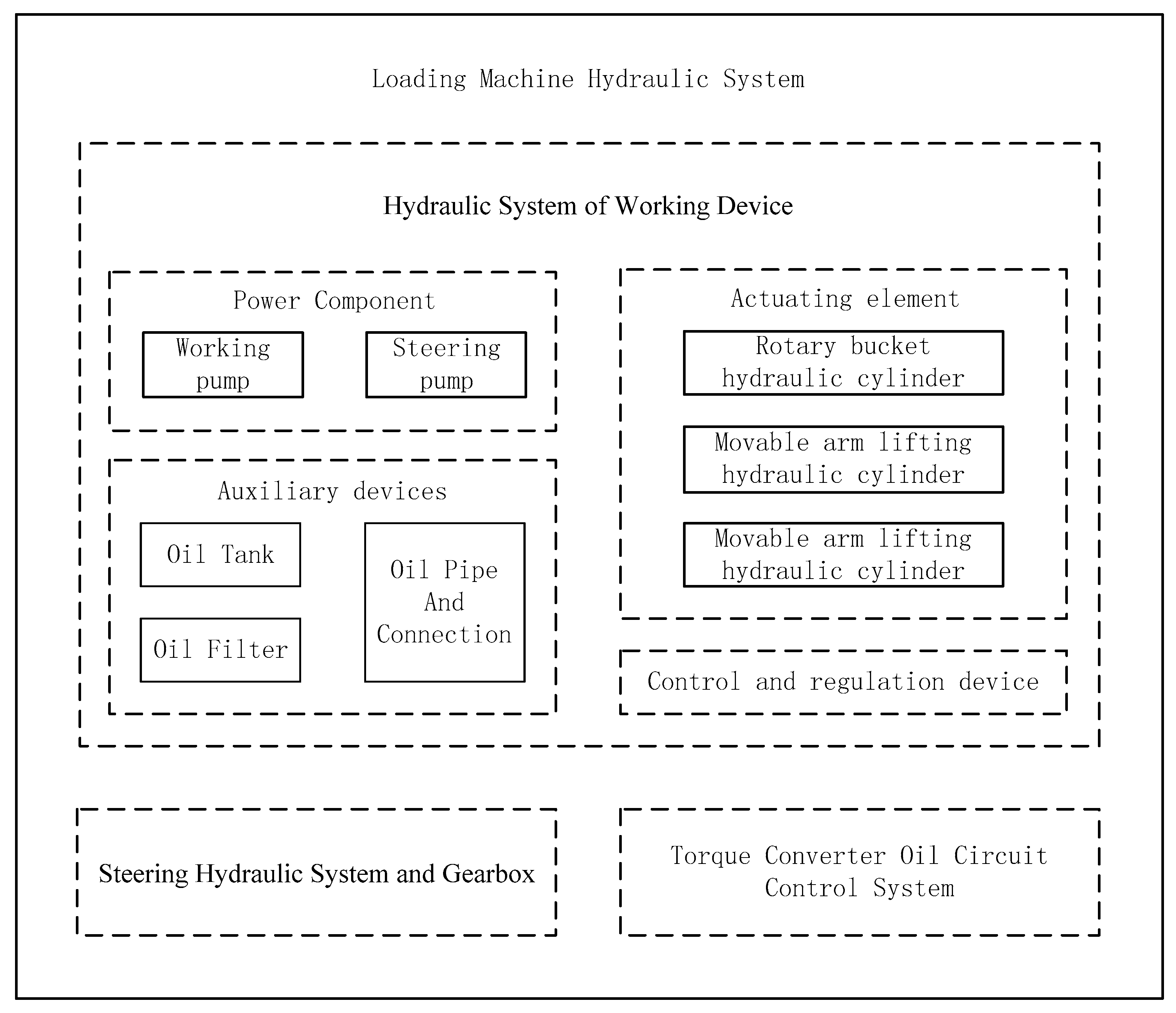
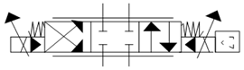
The main components of the loader’s hydraulic system mentioned here are shown in Figure 2.
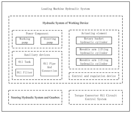
Figure 2.
Theloader’s hydraulic-system diagram.
The hydraulic system of the loader is mainly composed of three parts: the hydraulic system of the working device, the steering hydraulic system and gearbox, and the torque-converter oil-circuit control system [24]. When the steering gear is not working, the flow of the steering pump flows into the working hydraulic system to supply energy for the moving-arm cylinder or the rotary-bucket cylinder to realize the relationship between the steering hydraulic system and the working hydraulic system. The hydraulic system of loader’s working device is the core part of the entireloader’s hydraulic system. Its dynamic performance directly affects the loader’s work efficiency and work sensitivity [25].
The hydraulic system of the working device of a loader consists of four parts:
- (1)
- The Power Component—the working pump and steering pump of this type of loader are CBGQ2100 and CBGQ2080, with medium and high pressure, respectively, a quantitative gear pump with a pump-rated speed of 2000 r/min, and a nominal displacement of 100 mL/rev and 80 mL/rev, respectively. The nominal pressure is 25 MPa and 16 MPa, respectively.
- (2)
- The Actuating element—one rotary-bucket hydraulic cylinder and two movable-arm lifting hydraulic cylinders.
- (3)
- A Control and regulation device—a valve used to control and regulate the fluid pressure, flow rate, and the direction of each part of the system. There is amulti-way reversing valve, an overload-relief valve, and so on in the system.
- (4)
- Auxiliary devices, including an oil tank, oil filter, oil pipe, and connection, etc.
The working principle of the hydraulic system of aloader is as follows: Start the engine and drive the hydraulic cylinder by controlling the control-valve core of the multi-way directional valve to realize the oil-circuit reversing. When the hydraulic oil does not rotate, the steering pump converges towards the working hydraulic system to reduce the displacement of the working pump and improve the working efficiency of the loader [26,27]. The mechanical energy of the prime mover is converted into the pressure energy of the liquid; the energy is transferred tothe pressure energy of the liquid; the pressure energy of the liquid is converted into mechanical energy so as to realize the straight-reciprocating and rotating motion of the working device [28,29].
2.2. Fluid Basic-Property Settings
When setting the basic properties of a fluid, the first itemto be given is the working temperature of the fluid. Liquid has many properties. There are three basic properties that affect its dynamic effect: density, elastic modulus, and viscosity. The bulk modulus reflects the compressibility of the liquid, and the viscosity determines the damping property of the liquid. In addition, under normal circumstances, the liquid contains air; hence, the cavitation phenomenon must also be considered. As shown in Table 1, the parameter settings for water as a working medium are given [30].

Table 1.
Fluid-medium parameter setting.
2.3. Nonlinear-Performance Matching of Hydraulic-Valve Throttles
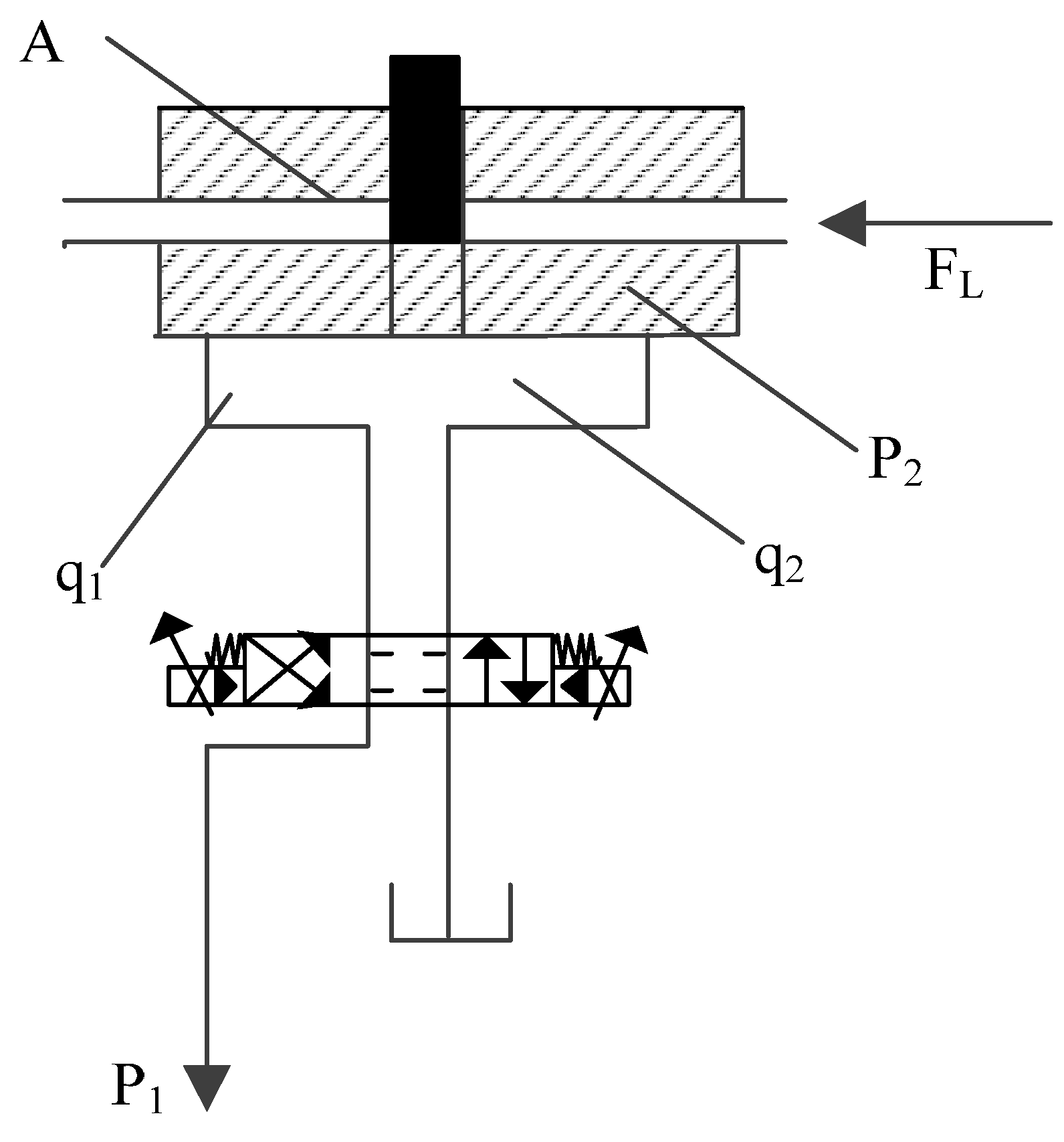
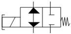
Figure 3 shows the simplified model of the throttle value of the hydraulic valve with speed regulation at the outlet.

Figure 3.
Symmetrical, simplified model of the hydraulic-valve throttle.
Among them, is the pressure drop of the hydraulic-throttle valve, is the effective working area of the symmetrical hydraulic valve, is the coefficient of viscous damping, is the modulus of oil-liquid elasticity, and is the coefficient of hydraulic leakage outside the cylinder.
Assuming that the throttle value of the hydraulic valve is and the piston displacement of the hydraulic cylinder is , according to the continuity of the flow rate of the hydraulic-throttle valve and the flow rate of the hydraulic cylinder, that the following can be concluded [31,32].
In the above formula, represents the flow rate at the outlet of the throttle valve, represents the coefficient of flow rate, and the value is 0.60. is the area gradient of the throttle window, is the density of the liquid, is the pressure drop of the hydraulic-throttle valve, is the volume of the inlet liquid from the piston of the hydraulic cylinder to the throttle valve, and is the pressure-drop variation of the hydraulic-throttle valve with time.
The displacement, , of the hydraulic-throttle valve is taken as the input of the nonlinear-model state space of the hydraulic system. Assuming that the system-input pressure, , is a constant value—that is, the pressure set by the relief valve—, , and . The space of the nonlinear-model state of the hydraulic system can be described as follows.
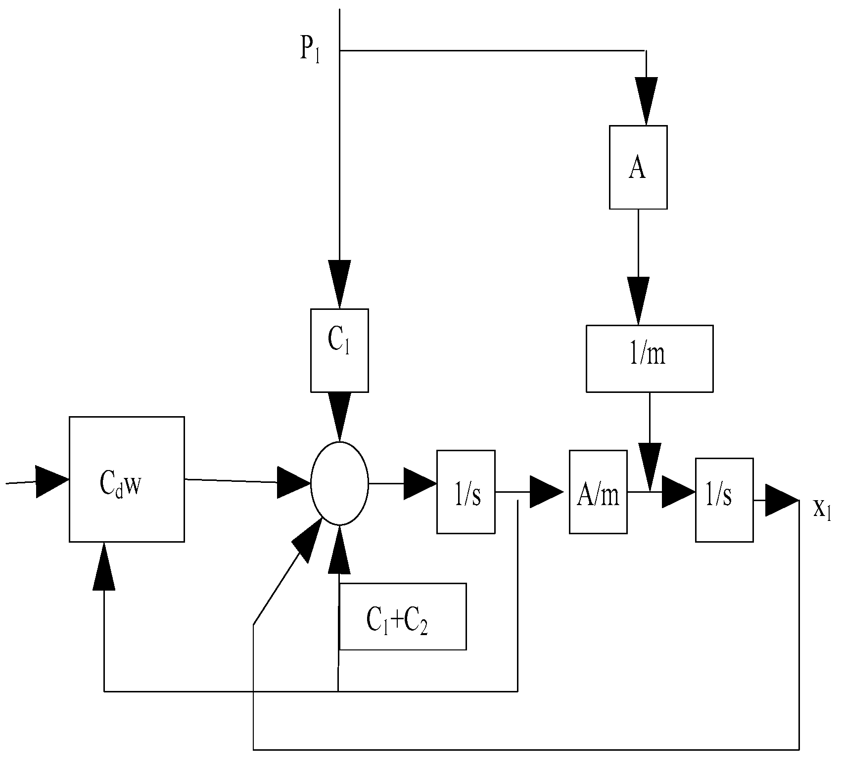
The structural diagram of the hydraulic system is shown in Figure 4.
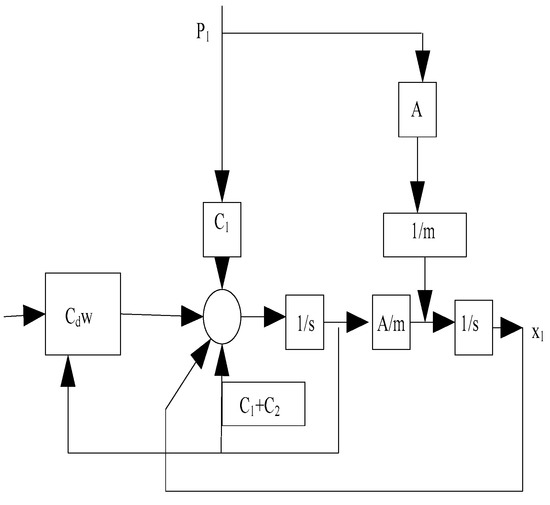
Figure 4.
Structural diagram of the hydraulic system.
It can be seen from Equation (3) that the throttle system of the hydraulic valve is nonlinear, the calculation amount is large, and obtaining the characteristic parameters is difficult; therefore, it needs to be linearized.
For the state-space description of the input–output nonlinear system, the corresponding nonlinear-standard form can be expressed as follows.
In Equation (4), and are smooth-vector fields, and is the output of hydraulic system. Equation (5) is transformed into the following.
In the above formula, and .
It is easy to prove that matrix is equal to 2 and can meet the condition of pairing.
Under the action of the pressure-difference step-load change, the analysis of the transient-response performance of shows that the static-force balance equation of the piston of the hydraulic valve can be depicted as follows: . If the step-complex change, , increases, will increase, f will be reduced by , will remain unchanged, will decrease, the overshoot of pressure will increase, and the number of oscillations will increase. Therefore, the hydraulic system’s corresponding stability is reduced, and the time needed for hydraulic-system adjustments increases [33].
If the throttle opening of the hydraulic valve increases, increases. Under the condition that other parameters do not change, according to , increases, remains unchanged, and increases. Therefore, the overshoot, g, of pressure decreases, and the number of oscillations gradually decreases. Furthermore, the smoothness of the throttle system of the hydraulic valve significantly improved, and the adjustment time of the system isreduced [34].
3. Results
3.1. Experimental Analysis of Pressure-Overshoot Performance
The QCS-004-hydraulic system is used as anexperimental platform, including a single-rod hydraulic cylinder, quantitative vane pump, relief valve and pressure gauge, electromagnetic directional valve, WT-290 thermometer, L-11B throttle valve, Q-11B speed-regulating valve, BPR-50 pressure sensor, YD-22 dynamic strain gauge, TDS digital storage oscilloscope, oil filter, and DC power supply.
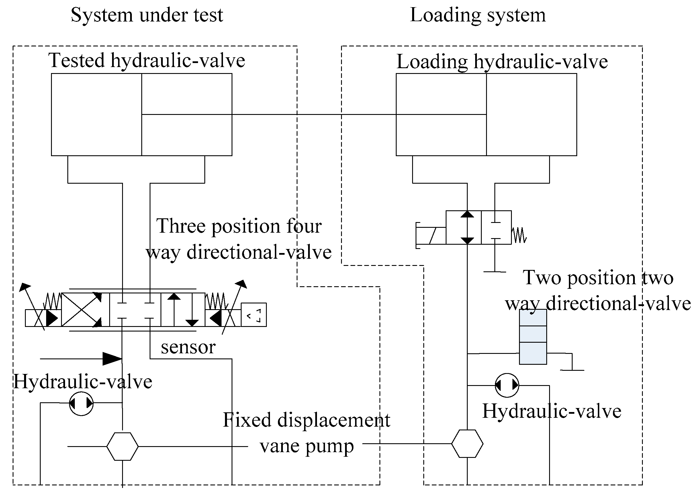
In order to analyze the dynamic influence of step-load changes due to the pressure difference inthe throttling performance of the hydraulic valve, the diagramof the experiment is shown in Figure 5. It can be divided into two parts: the tested system and the loading system. In the loading system, the piston-rod’s top block in the loaded hydraulic valve pushesthe piston-rod top block in the tested hydraulic valve, which can form the loading mode. In the loading system, the two-position two-way electromagnetic directional valve and the oil tank have different connection modes, which are on and off, respectively. When the hydraulic valve is on, the pressure of the loaded rodless cavity drops to 0. When the hydraulic valve is off, the pressure of the loaded rodless cavity rises from 0 to a certain value. For the measured hydraulic valve, a step load can be formed, and the pressure of the loaded rodless cavity can be used. The pressure sensor measures the pressure change in the tested hydraulic valve [35].
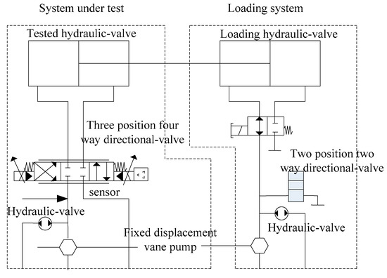
Figure 5.
Schematic diagram of the experiment.
Table 2.
Nomenclature Table.
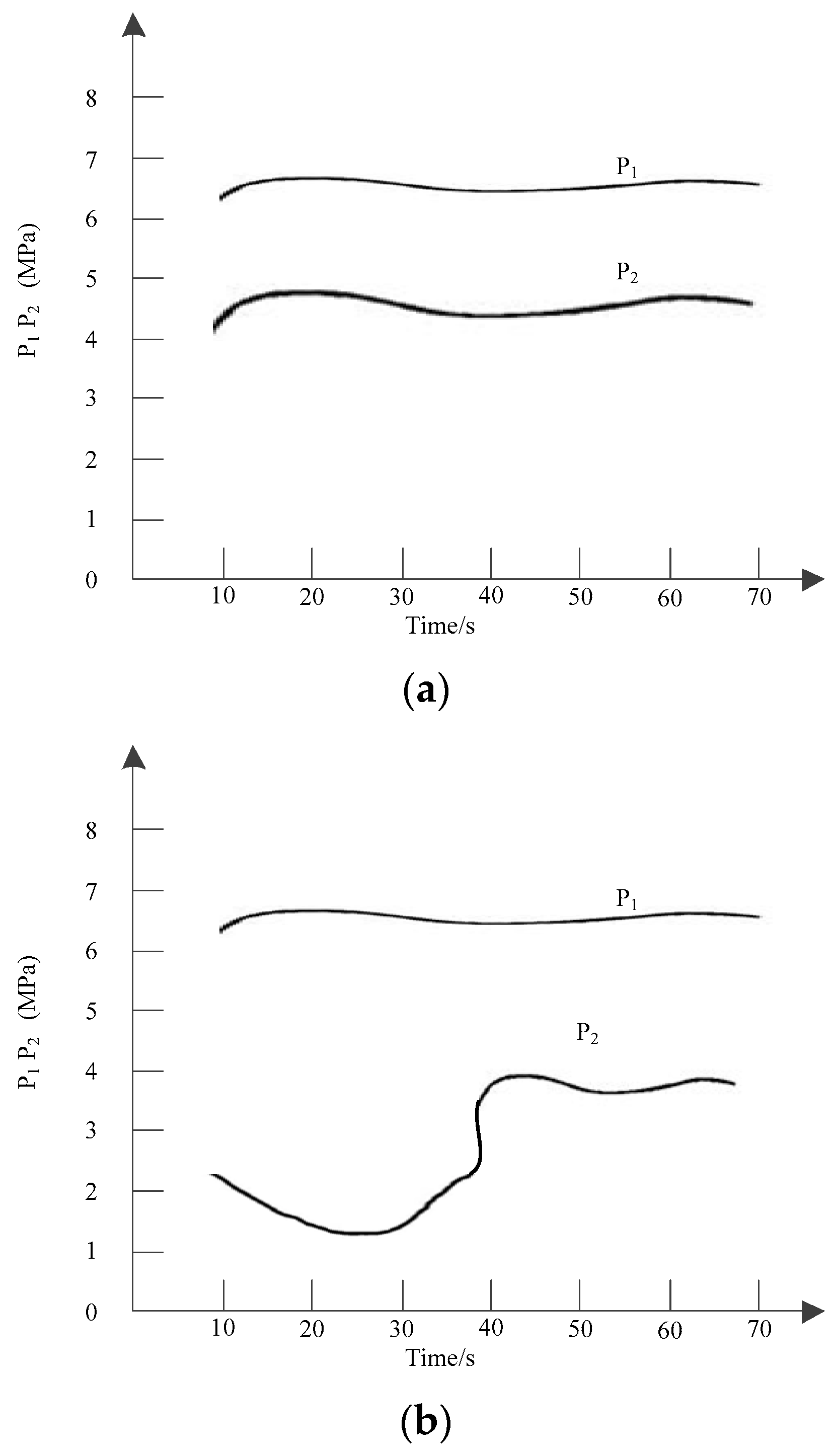
Figure 6 shows that the inlet pressure is 26 MPa and the step load is 8 Mpa. The process of obtaining the detection data of the inlet pressure is as follows: The transducer is directly placed in the chamber and when the hydraulic valve is throttled to a certain opening, the dynamic changes of the rod-free chamber pressure and the rod-chamber pressure of the hydraulic valve are recorded by the oscilloscope, and the data obtained arestored in the TDS-digital memory. It can be seen from Figure 6a that when the step load suddenly generates load, the pressure, , with the rod cavity of the hydraulic valve has a negative overshoot. As can be seen in Figure 6b, when the step load suddenly generates unloading, the pressure, , without the rod cavity of the hydraulic valve has a negative overshoot, and the pressure, , of the hydraulic valve with the rod cavity produces a positive overshoot.
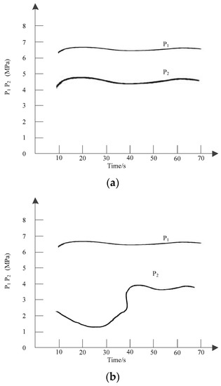
Figure 6.
Dynamic changes in hydraulic-valve pressure. (a) Loading of step load; (b) unloading of step load.
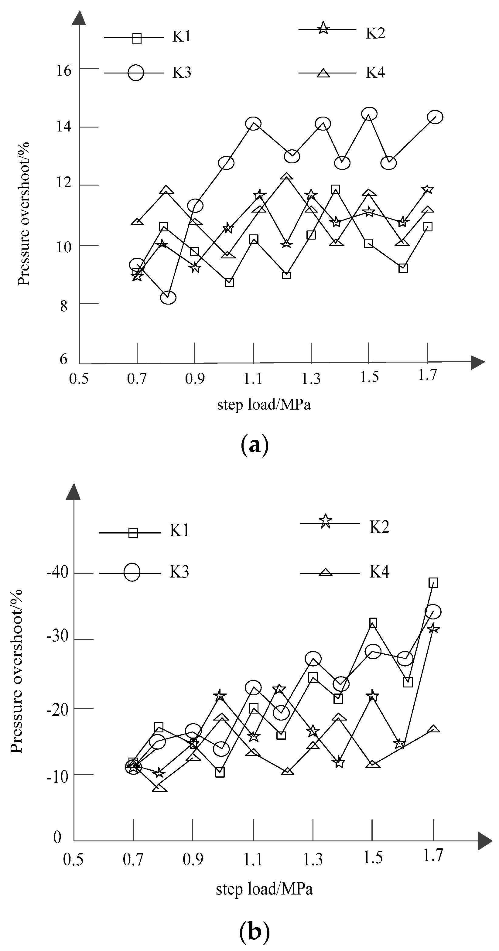
Figure 7 and Figure 8 show that, under the same inlet pressure and the same throttle opening, the absolute value of the pressure overshoot of the rodless chamber of the hydraulic valve increases with anincreasing step load, whether loading or unloading. Among them, K1–K4 are different throttle openings.

Figure 7.
Variations of the overshoot of the rodless cavity pressure. (a) Loading of step load; (b) unloading of step load.
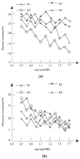
Figure 8.
Variations of the overshoot of pressure in the rod cavity. (a) Loading of step load; (b) unloading of step load.
In Figure 7a, with anincrease in the step load, the pressure-overshoot values also presented an overall upward trend, among which the pressure-overshoot value under the opening of the K3-throttle valve had the largest upward range, up to 14%, while the pressure-overshoot value under the opening of the K1 throttle valve had the smallest upward range, up to 12%. In Figure 7b, the numerical integration of the pressure-overshoot amount, along with the increase in the cascading step load, also presents arising trend, but its increasecompared to that of Figure 7a is greater, with anincrease in the step load of the K1 orifice under pressure super-tone contours of the biggest rise in the openings of the K4 orifice at a higher pressure than the minimum opening under the tone value.
Figure 8 describes the changes of pressure overshoot in the rod cavity. Figure 8a shows the changes of pressure overshoot in the rod cavity under step loading. The pressure overshoot drops the fastest at the opening of the K3 throttle valve, at whichthe lowest point is −10%. Figure 8b shows the changing diagram of pressure overshoots in the rod cavity unloaded by step loading. The overall downward trend is obviously faster than that inFigure 8a. The pressure-overshoot value under the opening of the K4-throttle valve is generally stable, but the overall level is low.
3.2. Dynamic-Performance Test of the Piston Rod in the Hydraulic System of the Loader
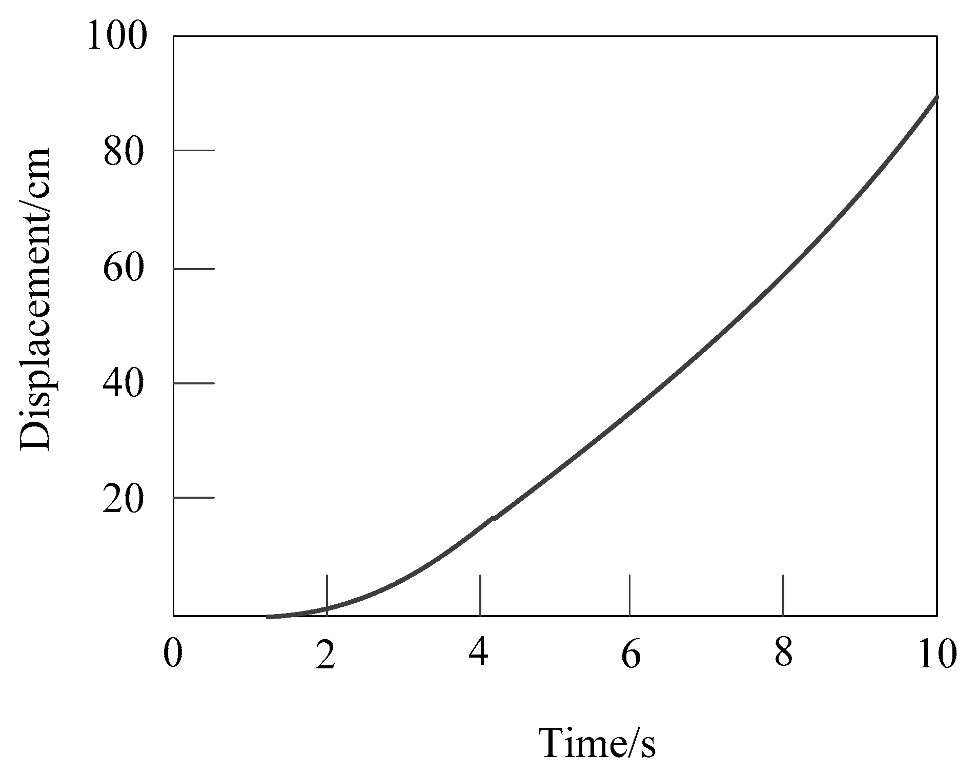
The dynamic laboratory experiment of the loader’s hydraulic system is realized by a pipeline connection, and the dynamic laboratory-experiment data of the hydraulic system arecollected. During steady-state measurements, a no-load test, confluent no-load test, loading test, and confluent-loading test shall be carried out on the hydraulic system of the loader by setting values of different rotational speeds of the motor, such as 1000 r/min, 1200 r/min, 1400 r/min, 1600 r/min, 1800 r/min, and 2000 r/min, by the upper computer; the values of the system’s torque, rotational speed, oil-supply pressure, oil-return pressure, oil-supply flow, oil-return flow, arm displacement, system efficiency, and input torque shall be measured, respectively, under the stable rotational speed of the above groups, and the data measured shall be displayed in anexcel table. In order to be clearer, the actual experimental data are collected in an Excel drawing display. With the working pump’s rotational speed set at 1000 r/min, the loader’s working-device arm-cylinder piston rod extending and shrinking in two-stroke displacements, measurements of the system’s supply and returnoil pressure, supply and return oil flow, and time of the curve, the experimental results were as follows (Note: According to the installation of the displacement sensor, the measured data and piston-rod extension and retraction of the actual movement mode and the displacement-time image in this paper were processed, as shown in Figure 9 and Figure 10.).

Figure 9.
Displacement and time curve of the piston-rod’s extension of the no-load boom.
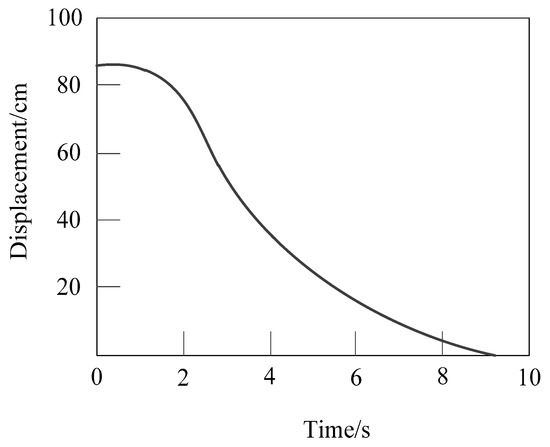
Figure 10.
Curve of the boom-piston rod-contraction’s displacement and time.
It can be seen from Figure 5 and Figure 10 that the displacement of the piston-rod’s extension and contraction is roughly proportional to time: that is, the speed of the piston-rod’s extension and retraction is fixed, and the retraction time is shorter than that of extension, which indicates that the speed of the piston rod is faster when retracting [36].
3.3. Optimization of Parameter Matching
In the design of the hydraulic valve, the parameter selection of hydraulic components is an important part. If the parameters of hydraulic components are calculated and selected according to the traditional static index and static characteristic formula, the result of the selection is relatively high.
After studying the dynamic characteristics of the hydraulic pressure with the step load of the hydraulic-valve throttle’s speed-regulation system, the dynamic influence of the pressure overshoot is used to modify the calculation formula of the selection of hydraulic-component parameters. Taking the selection of the throttle-rated pressure of the hydraulic valve as an example, the pressure overshoot is used to modify the selection of the rated pressure.
In Equation (7), represents the maximum working pressure of the hydraulic components, represents the overshoot of pressure in the rodless cavity of the hydraulic valve, and represents the sum of the pressure loss of the throttling-speed regulation.
4. Discussion and Conclusions
The dynamic modeling of the hydraulic-valve throttle’s speed-regulation system was carried out. The influence of the pressure difference, step load, and throttle opening on the throttling performance of the hydraulic valve was studied. In order to reduce the influence of experimental error, the dynamic experimental study of the throttle’s speed-regulation of the hydraulic valve was carried out. Based on a fluid-mechanics analysis, the nonlinear-performance matching of the hydraulic valve’s throttling was studied in this paper so as to realize the performance-matching optimization of the loader’s hydraulic system. The experimental results show that the experimental data areconsistent with theoretical data, which provides a reference for the throttling of the hydraulic valve and provides a basis for the component parameters in this paper. Compared with the simulation’s results, the hydraulic system can adapt to complex working conditions, and the performance parameters of piston-rod change and pressure overshoot are reasonable. However, there are still some limitations in this paper. For example, the hydraulic system of the loader studied in this paper is that of a low-pressure machine, and does not consider the performance-matching optimization of medium-pressure machines and high-pressure machines. In order to improve the results of this study, follow-up work will focus on the performance-matching optimization of the hydraulic system of the loader under different pressure levels. It is expected that it willprovide references for research studies onthe loader’s hydraulic system under stable-fluid conditions.
Author Contributions
H.W. and S.Y. collected the samples. H.W. and T.L. analysed the data. S.Y. and T.L. conducted the experiments and analysed the results. All authors have read and agreed to the published version of the manuscript.
Funding
This research received no external funding.
Institutional Review Board Statement
This article does not contain any studies with human participants performed by any of the authors.
Informed Consent Statement
Not applicable.
Data Availability Statement
All data generated or analysed during this study are included in this published article.
Conflicts of Interest
The authors declare no conflict of interest.
References
- Cheng, J.; Yuan, G.; Zhou, M.; Gao, S.; Liu, C.; Duan, H. A fluid mechanics-based data flow model to estimate VANET capacity. IEEE Trans. Intell. Transp. Syst. 2019, 21, 2603–2614. [Google Scholar] [CrossRef]
- Maziar, R.; Alireza, Y.; Em, K.G. Hidden fluid mechanics: Learning velocity and pressure fields from flow visualizations. Science 2020, 367, 1026–1030. [Google Scholar]
- Rajeev, S.G. Infinitesimal quantum group from helicity in fluid mechanics. Mod. Phys. Lett. A 2020, 35, 2050245. [Google Scholar] [CrossRef]
- Lutz, B.D.; Brown, S.A.; Perova-Mello, N. Exploring practicing engineers’ understanding of fluid mechanics concepts. Int. J. Eng. Educ. 2019, 35, 535–547. [Google Scholar]
- Mossa, M. The recent 500th anniversary of Leonardo da Vinci’s death: A reminder of his contribution in the field of fluid mechanics. Environ. Fluid Mech. 2020, 21, 1–10. [Google Scholar] [CrossRef]
- Deng, G.F.; Gao, Y.T.; Ding, C.C.; Su, J.J. Solitons and breather waves for the generalized Konopelchenko-Dubrovsky-Kaup-Kupershmidt system in fluid mechanics, ocean dynamics and plasma physics. Chaos Solitons Fractals 2020, 140, 110085. [Google Scholar] [CrossRef]
- Zhou, X.; Bai, Y.; Nardi, D.C.; Wang, Y.; Wang, Y.; Liu, Z.; Picón, R.A.; Flórez-López, J. Damage Evolution Modeling for Steel Structures Subjected to Combined High Cycle Fatigue and High-Intensity Dynamic Loadings. Int. J. Struct. Stab. Dyn. 2022, 22, 2240012. [Google Scholar] [CrossRef]
- Minichiello, A.; Armijo, D.; Mukherjee, S.; Caldwell, L.; Kulyukin, V.; Truscott, T.; Elliott, J.; Bhouraskar, A. Developing a mobile application-based particle image velocimetry tool for enhanced teaching and learning in fluid mechanics: A design-based research approach. Comput. Appl. Eng. Educ. 2020, 29, 517–537. [Google Scholar] [CrossRef]
- Wrat, G.; Bhola, M.; Ranjan, P.; Mishra, S.K.; Das, J. Energy saving and fuzzy-PID position control of electro-hydraulic system by leakage compensation through proportional flow control valve. ISA Trans. 2020, 101, 269–280. [Google Scholar] [CrossRef] [PubMed]
- Das, R.; Mishra, S.C.; Ajith, M.; Uppaluri, R. An inverse analysis of a transient 2-D conduction–radiation problem using the lattice Boltzmann method and the finite volume method coupled with the genetic algorithm. J. Quant. Spectrosc. Radiat. Transf. 2008, 109, 2060–2077. [Google Scholar] [CrossRef]
- Kundu, B.; Das, R.; Lee, K.-S. Differential Transform Method for Thermal Analysis of Exponential Fins under Sensible and Latent Heat Transfer. Procedia Eng. 2015, 127, 287–294. [Google Scholar] [CrossRef]
- Singla, R.K.; Das, R. Application of Adomian decomposition method and inverse solution for a fin with variable thermal conductivity and heat generation. Int. J. Heat Mass Transf. 2013, 66, 496–506. [Google Scholar] [CrossRef]
- Panda, S.; Bhowmik, A.; Das, R.; Repaka, R.; Martha, S.C. Application of homotopy analysis method and inverse solution of a rectangular wet fin. Energy Convers. Manag. 2014, 80, 305–318. [Google Scholar] [CrossRef]
- Barbarelli, S.; Amelio, M.; Castiglione, T.; Florio, G.; Scornaienchi, N.M. Design and analysis of a new wave energy converter based on a point absorber and a hydraulic system harvesting energy from waves near the shore in calm seas. Int. J. Energy Res. 2020, 45, 661–690. [Google Scholar] [CrossRef]
- Bai, Y.; Nardi, D.C.; Zhou, X.; Picón, R.A.; Flórez-López, J. A new comprehensive model of damage for flexural subassemblies prone to fatigue. Comput. Struct. 2021, 256, 106639. [Google Scholar] [CrossRef]
- Rahman, R.; Zhu, H.P.; Yu, A.B. Numerical Analysis of Effects of Specularity Coefficient and Restitution Coefficient on the Hydrodynamics of Particles in a Rotating Drum. Processes 2022, 10, 167. [Google Scholar] [CrossRef]
- Palevicius, A.; Janusas, G.; Cekas, E.; Patel, Y. Composite Piezoelectric Material for Biomedical Micro Hydraulic System. In International Conference on Bioinformatics and Biomedical Engineering; Rojas, I., Ortuño, F., Eds.; Springer: Cham, Switzerland, 2018; Volume 10814. [Google Scholar]
- Park, C.E.; Choi, J.H.; Lee, G.C.; Lee, S.Y. Multidimensional Hydraulic Solver Using Structured and Unstructured Meshes for the System Thermal-Hydraulic Code Space. Nucl. Technol. 2018, 205, 77–93. [Google Scholar] [CrossRef]
- Boedeker, S.; von Delius, S.; Neu, B.; Weber, A.; Schmid, R.; Frimberger, E.; Abdelhafez, M. Electrohydraulic lithotripsy (EHL) with a short-access-mother-baby-system (SAMBA) for the therapy of complicated bile duct stones (SAMBA-EHL STUDY). Endoscopy 2019, 51, OP34. [Google Scholar] [CrossRef]
- Xiao, Y.; Bai, C.; Chen, Y.; Yan, W.; Du, J.; Yu, T.; Zhang, J. Effect of gas extraction on the hydrodynamics in a fluidized bed membrane reactor at elevated temperatures. Asia-Pac. J. Chem. Eng. 2019, 14, e2338. [Google Scholar] [CrossRef]
- Zhang, L.; Huang, M.; Xue, J.; Li, M.; Li, J. Repetitive mining stress and pore pressure effects on permeability and pore pressure sen-sitivity of bituminous coal. Nat. Resour. Res. 2021, 30, 4457–4476. [Google Scholar] [CrossRef]
- Yan, X.; Meng, S.; Wang, A.; Wang, L.; Cao, Y. Hydrodynamics and separation regimes in a cyclonic-static microbubble flotation column. Asia-Pac. J. Chem. Eng. 2018, 13, e2185. [Google Scholar] [CrossRef]
- Wang, Z.-J.; Qiang, H.-F. Mechanical properties of thermal aged HTPB composite solid propellant under confining pressure. Def. Technol. 2021, 18, 618–625. [Google Scholar] [CrossRef]
- Krawczyk, R.; Słania, J.; Golański, G.; Nawrocki, J. Analysis of the reasons for crack in a tank of the hydraulic system. Eng. Fail. Anal. 2020, 116, 104716. [Google Scholar] [CrossRef]
- Shaikh, J.; Bordoloi, S.; Yamsani, S.K.; Sekharan, S.; Rakesh, R.R.; Sarmah, A.K. Long-term hydraulic performance of landfill cover system in extreme humid region: Field monitoring and numerical approach. Sci. Total Environ. 2019, 688, 409–423. [Google Scholar] [CrossRef] [PubMed]
- Simic, M.; Herakovic, N. Characterisation of energy consumption of new piezo actuator system used for hydraulic on/off valves. J. Clean. Prod. 2020, 284, 124748. [Google Scholar] [CrossRef]
- Casamor, M.; Martinez-Quiroga, V.; Reventós, F.; Mendizábal, R.; Freixa, J. On the scaling of uncertainties in thermal hydraulic system codes. Ann. Nucl. Energy 2019, 136, 107026. [Google Scholar] [CrossRef]
- Yao, J.; Lu, B.; Zhang, C.; Sadatomi, M. Optimal design of hydraulic system for an industrial press machine for performance im-provement and noise reduction. Open J. Mech. Eng. 2016, 1, 19–24. [Google Scholar]
- Xin, C.; Li, Z.; Zhang, Q.; Peng, Y.; Guo, H.; Xie, S. Investigating the output performance of triboelectric nanogenerators with single/double-sided interlayer. Nano Energy 2022, 100, 107448. [Google Scholar] [CrossRef]
- Yang, Z.; Xu, P.; Wei, W.; Gao, G.; Zhou, N.; Wu, G. Influence of the Crosswind on the Pantograph Arcing Dynamics. IEEE Trans. Plasma Sci. 2020, 48, 2822–2830. [Google Scholar] [CrossRef]
- Chaudhuri, S.; Saha, R.; Chatterjee, A.; Mookherjee, S.; Sanyal, D. Adaptive neural-bias-sliding mode control of rugged electrohydraulic system motion by recurrent Hermite neural network. Control Eng. Pract. 2020, 103, 104588. [Google Scholar] [CrossRef]
- Villarreal, R.; Lozano, L.A.; Salazar, M.P.; Bellora, G.L.; Melani, E.M.; Polich, N.; Soracco, C.G. Pore system configuration and hydraulic properties. Temporal variation during the crop cycle in different soil types of Argentinean Pampas Region. Soil Tillage Res. 2019, 198, 104528. [Google Scholar] [CrossRef]
- Castellanos, L.; Noguera, A.; Velásquez, E.I.G.; Caballero, G.E.C.; Lora, E.E.S.; Cobas, V.R.M. Mathematical modeling of a system composed of parabolic trough solar collectors integrated with a hydraulic energy storage system. Energy 2020, 208, 118255. [Google Scholar] [CrossRef]
- Zhang, F.; Cheng, L.; Gao, Y.; Xu, X.; Wang, Y. Fault tree analysis of a hydraulic system based on the interval model using latin hypercube sampling. J. Intell. Fuzzy Syst. 2019, 37, 8345–8355. [Google Scholar] [CrossRef]
- Zhou, W. Simulation of Hydraulic System Faults for Marine Machinery Based on AMESim. J. Coast. Res. 2019, 94, 357–361. [Google Scholar] [CrossRef]
- Chen, Y.; Li, J.; Lu, H.; Yan, P. Coupling system dynamics analysis and risk aversion programming for optimizing the mixed noise-driven shale gas-water supply chains. J. Clean. Prod. 2020, 278, 123209. [Google Scholar] [CrossRef]


Publisher’s Note: MDPI stays neutral with regard to jurisdictional claims in published maps and institutional affiliations. |
© 2022 by the authors. Licensee MDPI, Basel, Switzerland. This article is an open access article distributed under the terms and conditions of the Creative Commons Attribution (CC BY) license (https://creativecommons.org/licenses/by/4.0/).