Article

Orthogonal Optimization Design of the Compound Impeller for a New Type of Dishwasher Pump

1
National Research Center of Pumps, Jiangsu University, 301 Xuefu Road, Zhenjiang 212013, China
2
Ningbo FOTILE Kitchen Ware Co., Ltd., Ningbo 315336, China
*
Author to whom correspondence should be addressed.
Processes 2022, 10(9), 1813; https://doi.org/10.3390/pr10091813
Submission received: 24 August 2022 / Revised: 3 September 2022 / Accepted: 5 September 2022 / Published: 8 September 2022
(This article belongs to the Special Issue Design and Optimization Method of Pumps)

Abstract

:
A new type of dishwasher pump without a pipeline system was invented for the first time to form an original sink-type dishwasher avoiding the accumulation of dirt in the hydraulic system. In order to improve the hydraulic performance of this new type of dishwasher pump with twin-volute passive rotation driven by a compound impeller, an orthogonal optimal design method was first introduced to optimize the compound impeller composed of axial cascades and radial blades. Six geometric parameters were selected as the main factors to design the orthogonal table L18(36). All impeller models were manufactured via high-precision 3D printing and tested to determine the optimal solution. Firstly, the hydraulic performance was measured using a specially designed test bench under the assumption of static-volute conditions. Then, the optimization scheme was verified in real machine experiments under the rotating-volute condition, and numerical calculations were used to assess the performance improvement due to optimization under the static- and rotating-volute conditions. The results show that the main factors affecting the pump head and efficiency are impeller outlet diameter D2 and profile line L. The optimized pump head and efficiency are significantly higher than those of the original scheme. Furthermore, the entropy production of each flow passage component of this new type of dishwasher pump is significantly reduced after optimization. Under the static-volute condition, the scheme obtained using the range analysis displays an increase of 0.3 m in the pump head and 2.99% in pump efficiency. Under the rotating-volute condition, the optimization scheme is also effective (pump head increased by 0.54 m, and pump efficiency by 7.46%). At the same time, the passive rotation speed of the twin-volute increases from 60 rpm to 70 rpm, verifying that both the optimization method is reliable and can be used when developing and optimizing dishwasher pumps.

1. Introduction

Dishwashers are increasingly common household appliances that liberate human hands. However, traditional dishwashers are mostly built-in cabinet types, which cannot meet the needs of all users. For this reason, a sink-type dishwasher was developed, which is embedded into the traditional kitchen sink to save space. This new type of dishwasher pump structure design is outlined in ref. [1]. A detailed comparison with the traditional dishwasher is shown in Figure 1. Traditional dishwashers generally have complex pipeline sprinkler systems (Roman character I, which includes a pipeline and spray arm, such as shown in ref [2]). This leads to certain hydraulic loss in the pipeline, and it is easy to hide dirt in the complex pipe, which is not easy to disassemble for self-cleaning. Additionally, the pump (ordinary centrifugal pump) of a traditional dishwasher is placed at the bottom of the water tank, which is inconvenient to disassemble for self-cleaning. Therefore, under the conditions of saving space, easy disassembly, compact structure, and prevention of secondary pollution, we innovatively developed a new type of sink-type dishwasher, whose original core structure is a new type of dishwasher pump (Roman character II). As can be seen from Figure 1, the innovative dishwasher pump is a combination of the twin-volute and spray arm, resulting in open cleaning without a pipeline system. At the same time, a new type of compound impeller within the basic circle is used to drive a twin-volute spray arm (Roman character III, which includes nozzles and profile of flow channel of twin-volute). The new type of dishwasher pump also includes an entrance section, DC motor, and nozzles. Except for the DC motor, all other components are located in the sink and are easy to disassemble for self-cleaning.
This new type of dishwasher pump requires improved hydraulic performance to obtain a greater performance advantage over the old sink-type dishwasher model. However, there are several problems in pump performance improvement that need to be solved: (1) as shown in Figure 1, the outlet of the pump becomes multiple nozzle jet outlets, resulting in the difficult measurement of outlet pressure without a pipeline. (2) In Figure 1, the computational domain of the new type of dishwasher pump (Roman character IV) shows that the actively rotating impeller drives the volute to rotate passively. Unlike traditional pumps, the volute does not rotate, which makes pump performance testing more difficult. Additionally, the performance of the pump must also consider the passive rotation speed of the volute, which also affects the rotary jet cleaning. (3) As the core component of the pump, the compound impeller structure used in the new type of dishwasher pump is more complex. The compound impeller is composed of axial cascades and radial blades, which both have the parameters of the axial flow impeller and the centrifugal impeller. However, it is neither a centrifugal pump nor an axial flow pump and has a combination of two types of traditional pump structures. This increases the number of parameters affecting the performance of the pump, making it more complicated than traditional pumps. Therefore, these special key points drive this type of pump in-depth to develop and optimize dishwasher pump design.
In traditional dishwasher research, several detailed and systematic studies of key dishwasher parts have already been carried out. These include studies on the spraying arm by Dedoussis and Giannatsis [3], adsorption dishwasher by Santori et al. [4], domestic and automatic dishwashers by Pérez-Mohedano et al. [5,6], and airflow field inside dishwashers measured by Minde [7]. Traditional dishwasher research mainly focuses on the research of spray arms, as shown in Figure 1 (Roman character I), while pumps are rarely in focus, which is due to the widespread application of the traditional pump structure in traditional dishwashers, which is a relatively mature technology. However, in this new type of dishwasher, both the pump structure and the operating principle will change. Therefore, this study will introduce the cleaning mechanism and research direction of the new dishwasher and provide a reference for the subsequent development of new dishwashers and model innovation.
In traditional pump research, the influence mechanism of multiple parameters has been widely studied. Zhang et al. [8] investigated the effect of the suction side blade profile on the performance of a side channel pump. It was indicated that its performance could be improved by increasing the angle on the suction side of the blade. Cui et al. [9] studied the influence of the blade outlet angle on the performance of a low-specific-speed centrifugal pump and showed that a larger blade outlet angle was beneficial to hydraulic performance. Fu et al. [10] carried out pressure fluctuation experiments to study the effect of stagger angles on the head, efficiency, and pressure fluctuation characteristics. They discovered that the stagger angles had negligible effects on the head characteristics and efficiency but significantly affected the pressure fluctuation characteristics. Sanjay et al. [11] introduced the effects of impeller diameter and rotational speed on the performance of a pump running in turbine mode. The authors also found that impeller trimming led to improvement in efficiency at partial load operating conditions. Mohammad et al. [12] investigated the effect of passage width, additional splitter blades, etc. The simultaneous modification of parameters in the range of part-load condition to over-load condition reduced losses but increased both the efficiency and power generation. Zeynel et al. [13] discussed the effect of the number of stages, the blade outlet spacing, and the blade outlet angle on the performance of an industrial electric submersible pump. Expanding the impeller output width resulted in increased pump efficiency at a certain rate, while the impeller output angle had a significant effect on the efficiency. The influence of various geometric parameters on the performance of traditional pumps (or pump mode [14]) is widely used to conduct in-depth research. However, in the case of the new type of dishwasher pump, the literature on its internal flow characteristics and geometric influence mechanisms is scarce, requiring further research.
Up to now, there has been little understanding of this innovative pump structure and the technology is still immature. Zhu et al. [15,16] investigated the unsteady pressure pulsation in this new type of dishwasher pump with a special double-tongue volute (twin-volute with passive rotation) using the experimental and computational fluid dynamics (CFD) method. The results revealed that there are different mechanisms between the single- and double-tongue volutes, as well as between the volute under static and rotating conditions. Ning et al. [1] further investigated the flow mechanism of this new type of dishwasher. However, their studies [1,15,16] were focused on novel rotor–stator interference and little consideration was given to the effect of geometric parameters on pump performance. Due to the specialty of the new type of pump structure, as shown in Figure 1, the research on its design and optimization methods is also scarce, which motivates the present study.
Optimization is an important way to determine the influence mechanisms of these parameters and to find the optimal solution. Sushil et al. [17] introduced the blade outlet angle, blade wrap angle, and blade outlet width as design variables for the impeller optimization using the response surface methodology with a multi-objective optimization algorithm. After optimization, the pump head and efficiency were increased by 9.154% and 10.15%, respectively. Shim et al. [18] used the blade outlet angle, the impeller outlet width, and the cross-sectional area of the volute as design variables and carried out the multi-objective design optimization by surrogate-based optimization techniques. The internal flow stability of the pump was successfully increased.
Several studies considered the method of orthogonal optimization for improving the performance of pumps. For instance, Xu et al. [19] used blade wrap angle, blade angles at impeller inlet and outlet, blade leading edge position, and blade trailing edge lean as design variables. Further, Zhao et al. [20] adjusted the blade number, bias angle in the peripheral direction of splitter blades, inlet diameter of splitter blades, and deflection angle of splitter blades. Finally, in refs. [21,22,23], orthogonal optimization on the influence of geometric parameters on pump performance was carried out and provided significant results. The orthogonal test optimization method has certain advantages when optimizing internal pump parameters; most importantly, it can obtain the primary and secondary order of the parameters affecting the pump performance. This is extremely important for the new type of dishwasher pump because the parameters of the new pump are nearly two times that of the traditional pump. If the main parameters affecting the performance are obtained, they will be considered in the design to save the research and development cycle. Hence, the orthogonal experiment optimization remains the best choice to investigate the parameter influence mechanisms and obtain the optimal solution for the new type of dishwasher pump.
For this reason, the compound impeller, as the core component of the new type of dishwasher pump, was taken as the research object. Firstly, referring to the parameter influence laws and empirical design formulas of traditional pumps, several key parameters were identified for optimal design. The aim of the optimal design was to improve the new type of dishwasher pump performance in terms of some special parameters, such as hub cover height, which affects the passive rotation speed of twin-volute and is rarely selected as an optimization parameter in traditional pump research. Next, an orthogonal optimization table was established by selecting factors and levels of the final optimization scheme. The primary and secondary orders of the parameters affecting the pump performance were obtained experimentally based on the static-volute assumption. In the next step, the entropy production analysis method based on the steady numerical calculation results was introduced to analyze the reasons for performance improvement before and after the optimization under the static-volute condition. Finally, the prototype model test and unsteady numerical calculation of the optimization scheme were carried out to determine if the optimization scheme remained feasible under the real operating condition (i.e., rotating-volute condition). In other words, the aim of this step was to reveal the applicability of the orthogonal optimization method for a new type of dishwasher pump and to provide a reference for future optimal design.

2. Orthogonal Optimal Design of Compound Impeller Factors

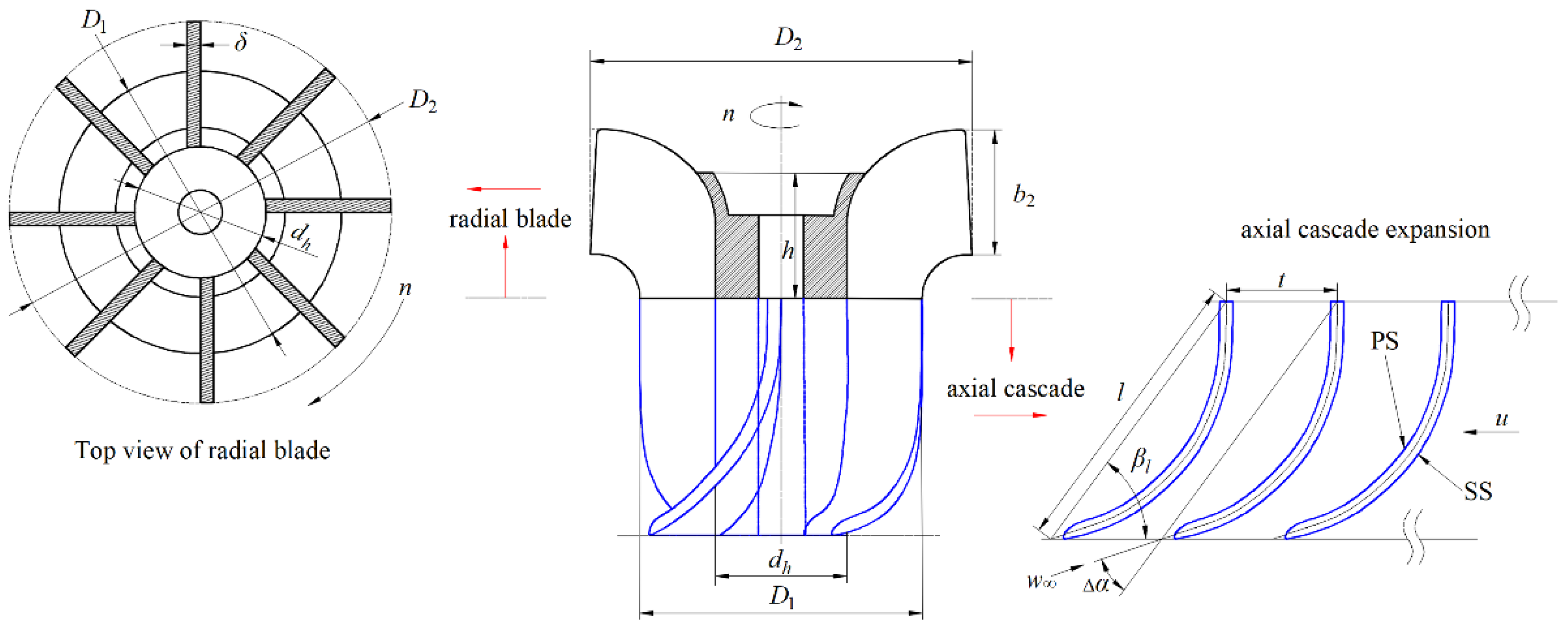
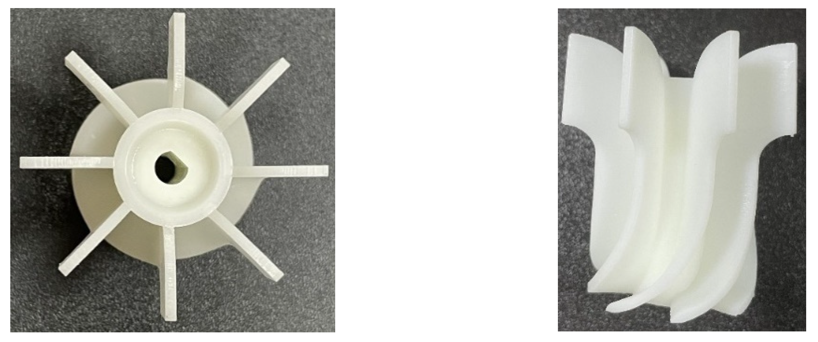
2.1. Geometry Parameters

Geometry parameters of the compound impeller composed of axial cascades and radial blades are shown in Figure 2. The axial cascade can be expanded planarly and belongs to both the plane cascade and the in-line cascade. According to Figure 2, the key geometric parameters of the axial cascade are tip diameter (D1), airfoil length (l), hub diameter (dh), airfoil setting angle (βl), cascade spacing (t = 2πR/z), and angle of attack (∆α). On the other hand, the critical radial blade geometric parameters are blade (or impeller) inlet diameter (D1), blade (or impeller) outlet diameter (D2), hub cover height (h), blade outlet setting angle (β2), and impeller outlet width (b2). Additionally, the shared geometry parameters of axial cascades and radial blades are blade number (z) and blade thickness (δ), in addition to the above coupling parameters D1 and dh.
The compound impeller structure is different from that of the traditional pump impeller structure. The internal flow state shows that there is a large loss area in the flow regime [1,15,16]. Hence, its structure must be further optimized to improve hydraulic efficiency.

2.2. Selection of Design Variables

Since this compound impeller is relatively rare in the traditional pump field and has a large number of influencing parameters, as shown in Figure 2, several key parameters should be selected for optimal design. This is mainly to improve the optimization efficiency and is conducted by referring to the preferred impeller structure parameters found in refs. [19,20,21,22,23].
The first key geometric parameter is axial cascades tip diameter D1, which is also the inlet diameter of the radial blade. According to the design experience in traditional centrifugal pumps, the impeller inlet diameter can be estimated according to:
D 1 = ( k 0 Q n 3 ) 2 + d h 2 ,
where Q is the pump flow rate, n is the rotational speed of the compound impeller, and k0 is the correction coefficient (its value ranges between 3.2 and 5.5).
Since the flow rate Q = 55 L/min, the rotational speed n = 3000 rpm, and the hub diameter dh = 14.9 mm, it can be concluded that the blade inlet diameter D1 ranges between 27.9 mm and 39.8 mm. While the original compound impeller inlet diameter is 32 mm, its value is within the range estimated by Equation (1). Therefore, the optimization range of radial blade inlet diameter can be initially selected based on Equation (1), i.e., 30 mm, 32 mm, and 34 mm.
The second key geometric parameter is blade outlet diameter D2. Based on the traditional centrifugal pump design experience, it can be estimated according to:
D 2 = k D 2 Q n 3 ,
where kD2 is the correction coefficient defined as:
k D 2 = ( 9.35 9.6 ) ( n s 100 ) 1 / 2 ,
with the specific speed ns being:
n s = 3.65 n Q H 3 / 4 .
Through Equations (2)–(4), the blade outlet diameter D2 is determined to be in the range of 45.08 mm and 46.28 mm. Considering that the diameter of the volute base circle is 46.3 mm, the compound impeller blade outlet diameter D2 slightly deviates from the traditional estimation. Hence, based on the original value, D2 is selected as 41 mm, 43 mm, and 45 mm, as calculated via Equation (2), with variations within the range of 11.4%.
The third key geometric parameter is the impeller outlet width b2. In the traditional centrifugal pump design, it is usually calculated using the velocity coefficient method:
b 2 = k b Q n 3 .
According to the statistical data, the correction coefficient kb is calculated by:
k b = 1.3 ( n s 100 ) 3 .
Another common empirical formula for determining the correction coefficient kb is:
k b = 0.64 ( n s 100 ) 5 / 6 .
The impeller outlet width b2 obtained through Equations (5)–(7) is 7.59 mm and 24.25 mm, respectively. Further, based on the original and calculated estimations, the recommended impeller outlet width b2 values are 12 mm, 14 mm, and 16 mm.
The three above-defined parameters are relatively common and have a significant impact on the pump head and efficiency. Moreover, several parameters are special for the new type of dishwasher pump. One of those is the blade outlet setting angle β2, which also affects the performance of traditional centrifugal pumps. However, in the new type of dishwasher pump, β2 is an important parameter affecting the passive rotation of the twin-volute. Unfortunately, the influence mechanism of β2 is not yet clear. Therefore, referring to the characteristics of the traditional back-curved blades, radial blades, and forward-curved blades, β2 is selected as 60°, 90°, and 120°, respectively, to determine the associated influence law, as shown in Figure 3.
Another special factor that significantly affects the passive rotation of the twin-volute is the hub cover height h with a few research recommendations available. However, its effect mechanism for the new type of dishwasher pump performance is not yet clear. Therefore, the values of h = 13 mm, 14 mm, and 15 mm are selected based on the original scheme.
Most of the parameters outlined above refer to the design experience in the field of traditional centrifugal pumps. However, for the compound impeller in the new type of dishwasher pump, some special parameters need to be considered involving the axial cascade at the bottom of the impeller. There are multiple airfoil parameters, as shown in Figure 2, and a single airfoil geometry is selected for the parameter optimization, profile line L. Variable L was designed by changing the blade airfoil length (l) and setting the airfoil angle (βl) to alter the blade cascade parameters. Therefore, based on the original scheme, profile line L can be obtained by increasing and decreasing l and βl, as shown in Figure 4. The associated βl values are 48.4°, 53.5°, and 59.4°on the shroud side, and 64.9°, 71.7°, and 79.6° on the hub side, respectively.

2.3. Optimization Object and Orthogonal Scheme Design

As can be seen from Figure 1, the optimization goal of the new sink-type dishwasher is complex, which is also affected by the nozzle position and the placement of the reference dishes. Therefore, referring to the requirements of traditional dishwashers for pumps, as well as a lot of test experience of new sink-type dishwashers, the performance requirements for the new dishwasher are that the head must not be lower than 2 m, but not too large (do not exceed 3 m), which will cause a large water flushing noise. When the head exceeds 2 m, efficiency will be the first optimization goal. Additionally, the passive rotation speed of the volute is in the range of less than 100 rpm. Within this range, the higher the rotation speed, the better the cleaning effect. Obviously, in terms of optimization goals, the new type of dishwasher pump is very different from the traditional dishwasher pump.
Based on the selection of factors and levels, six factors were selected for the orthogonal experimental design method used in this paper. Each factor was given assigned levels, meaning that the selected orthogonal scheme was L18(36), which is comparable to the standard orthogonal table. Table 1 shows the three-level values corresponding to the six factors from the orthogonal table. Further, the alphabetic symbols A, B, C, D, E, and F represent the profile line L (see Figure 4), the blade inlet diameter D1 (the axial cascade tip diameter), the impeller outlet diameter D2, impeller outlet width b2, hub cover height h, and blade outlet setting angle β2, respectively.
According to the orthogonal table design principle, the orthogonal test scheme with six factors and three levels was obtained based on L18(36), as shown in Table 2, with a total of 18 design schemes. These 18 compound impeller models were all created via 3D printing, as shown in Figure 5. Next, all 18 impeller schemes were tested on the hydraulic characteristic test bench to determine how the six parameters affect the performance of the proposed dishwasher pump design.

3. Experimental Analysis of Orthogonal Optimization Scheme

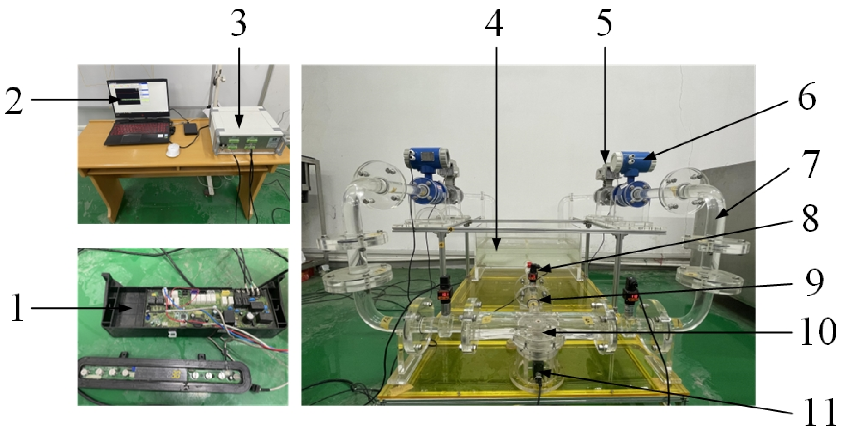
3.1. Hydraulic Characteristic Test

It is hard to obtain the flow rate and pressure measurements for the proposed dishwasher pump due to the rotation of its twin-volute, which includes 13 nozzle outlets and is not connected to the pipeline, as shown in Figure 1. Therefore, by referring to the hydraulic characteristic test bench of the traditional pump design, the twin-volute was firstly designed to be static, and the nozzle outlet was altered to the equivalent outlet on both sides of the twin-volute, enabling the pressure and flow rate measurements.
The characteristic hydraulic test bench developed for the proposed dishwasher pump is shown in Figure 6. It is composed of four parts, an inlet pipeline, pump, outlet pipeline, and tank. The simplified twin-volute has two outlets; therefore, the test bench outlet pipeline is composed of two sets of symmetrical pipes. The SCYG410 intelligent pressure sensor was installed at both the inlet and outlet pipelines. The measurement accuracy of the pressure sensor was 0.2% FS. Considering that the pressure variation ranges at the inlet and outlet, the pressure sensor measurement range was selected as −20 kPa to 20 kPa at the inlet and 0 kPa to 30 kPa at the outlet, respectively. The flow rate was measured via the BLD-DN40 electromagnetic flowmeter, with a measurement range between 10 L/min and 333 L/min and measurement accuracy of 0.5% FS. The flow rate was controlled and adjusted by the Q911F-16P solenoid valve with an opening that can be controlled through an external electric actuator. The torque was measured via a torque sensor (model HLT-171-0.5), which simultaneously measures the impeller rotation speed. The motor power can be displayed online, and the measurement range was between 0 N·m and 0.5 N·m with an accuracy of 0.2% FS.
The uncertainties of test measurement can be divided into systematic uncertainty and random uncertainty. The former is mainly determined by the instrument measurement accuracy. Based on the test instrument accuracy defined by the manufacturer and the measurement principle for the proposed pump, the system uncertainties of the head, efficiency, and power were obtained to be ±1.29%, ±1.48%, and ±0.09%, respectively. The latter is mainly caused by the random external unstable factors that occurred during the test. To reduce it, repeated measurements are required. The value of random uncertainty is calculated by continuously sampling the flow rate, head, rotation speed, and torque under the same condition 10 times. A confidence level of 95% was selected to determine the confidence coefficient as 2.23 for a total of 10 measurements. Thus, the random uncertainties of the head, efficiency, and power were calculated to be ±1.09%, ±1.57%, and ±0.57%, respectively. The comprehensive uncertainty was calculated next using the systematic and the random uncertainty, which was ±1.69% for the head, ±2.16% for the efficiency, and ±0.57% for the power. Obviously, the measurement values for head, efficiency, and power were all within the required range of ±2.30% (Class C), confirming that the test results are both accurate and credible.

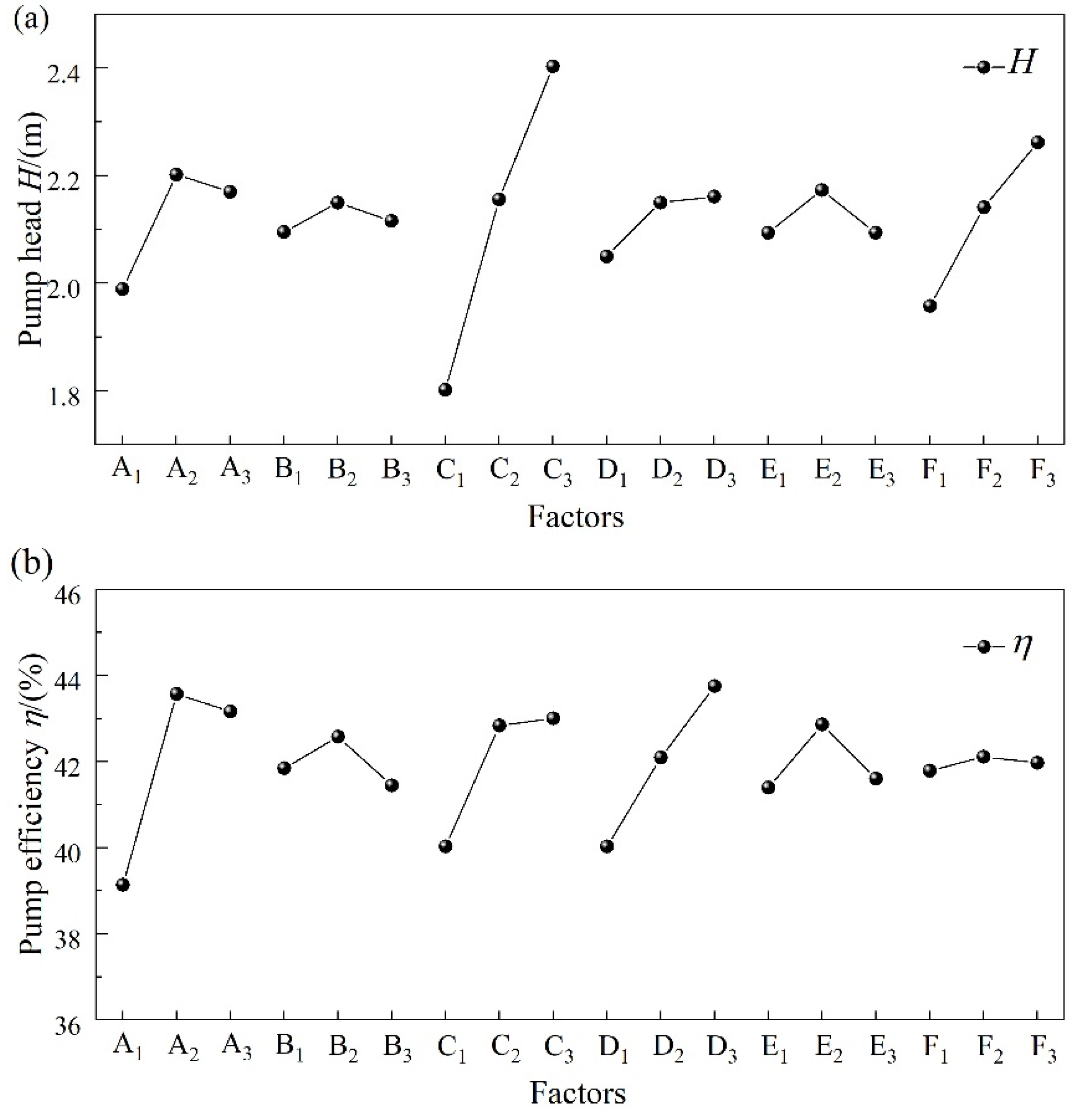
3.2. Direct Analysis of Orthogonal Experiment Scheme

The 18 orthogonal impeller schemes shown in Figure 5 were tested on the hydraulic characteristic test bench (Figure 6). The test results for the pump head H and efficiency η under the design conditions (1.0 Qd) are shown in Figure 7. Direct analysis of orthogonal test results showed that, under the rated flow condition, the impeller head of the 18th scheme, which was 2.524 m, was the highest among the observed cases. As such, it was 0.284 m higher than the original scheme. Its efficiency was 43.324%, with an increase of 0.804% compared to the original scheme. In terms of efficiency, the highest among the tested cases was the 10th scheme, which was 45.44% (or 2.92% higher than the original scheme); correspondingly, the height was 2.363 m (i.e., 0.123 m higher than the original scheme).
For the new type of dishwasher pump, the pump head needs to exceed 2 m to meet the pressure requirements. Too high pressure will cause noise and energy waste, whereas too low pressure will not achieve the cleaning effect. In this case, efficiency becomes the primary optimization goal. Hence, the 10th scheme is the most efficient even though it has a slightly lower head than the 18th scheme. Therefore, according to the direct analysis of the pump performance, the 10th scheme is optimal.

3.3. Range Analysis of Orthogonal Experiment Scheme

Aiming to determine the main factors affecting the hydraulic performance of the compound impeller, the range analysis method was used to analyze the orthogonal test results. The analysis was helpful to better determine the primary and secondary effects of various factors on pump performance and to determine its optimal level (i.e., to find the optimal combination).
As can be seen in Table 3 and Table 4, after comparing the magnitudes of ranges RH and Rη, the order of the influence for each factor on the pump head was as follows: C > F > A > D > E > B. Concerning the effect on the efficiency, the order was A > D > C > E > B > F. Therefore, factor C (i.e., the impeller outlet diameter D2) had the most significant impact on the pump head, while factor A (i.e., the profile line L) had the most significant impact on the pump efficiency.
The influence of each factor on the head and efficiency under the rated condition is shown in Figure 8. Both the pump head and efficiency increased with the impeller outlet diameter D2, which changed in the same way as the impeller outlet width b2. With the increase in the blade outlet setting angle β2, the pump head gradually increased; however, the pump efficiency firstly increased and then decreased. For the other three factors, including the profile line L, axial cascade tip diameter D1, and hub cover height h, the pump head and efficiency first increased and then decreased with the increase in the factor level. As shown in Figure 8, the best combination for the pump head was A2B2C3D3E2F3, while the best combination for pump efficiency was A2B2C3D3E2F2 under the rated condition.
For the new dishwasher pump, efficiency was taken as the first index to optimize design variables once the design requirement H ≥ 2 m was met. Therefore, after comprehensively considering the efficiency factors, the optimal compound impeller solution was A2B2C3D3E2F2. That is, the airfoil setting angle (βl) was 71.7° at the hub side and 53.5° at the shroud side, respectively. Further, the axial cascade tip diameter (D1) was 32 mm, the impeller outlet diameter (D2) was 45 mm, the impeller outlet width (b2) was 16 mm, the hub cover height (h) was 14 mm, and the blade outlet setting angle (β2) was 90°.
The optimal scheme obtained through the range analysis was 3D printed, as shown in Figure 9. Then, through the hydraulic performance test based on Figure 6, the results obtained for the original scheme and by direct analysis and range analysis were listed and compared in Table 5. It was found that the scheme pump head and efficiency obtained by the range analysis were slightly higher than those obtained via direct analysis (scheme 10 in Figure 5). Moreover, compared to the original scheme, the scheme obtained by the range analysis saw an increase of 0.3 m in the pump head and 2.99% in efficiency under the rated condition. Therefore, through the orthogonal test optimization, the scheme obtained through the range analysis was selected as the final design (Figure 9).

4. Results

4.1. Comparison of Optimization Scheme under the Static-Volute Condition

To better reveal the underlying mechanism for the improvement of hydraulic performance, both the original scheme and optimization schemes were compared using the CFD method under the static-volute condition. Details of the numerical simulation method are described in refs. [1,15,16]. The hydraulic performance of the new type of dishwasher pump, focusing on the differences between the original scheme and the optimization scheme under different flow conditions, was dictated by the CFD method (Figure 10). It is evident that the variation trend in the pump head and efficiency curves before and after the optimization was practically the same: the highest efficiency point moved towards a low flow rate condition. After optimization, the pump hydraulic performance was significantly improved. In other words, the pump head and efficiency after optimization were significantly higher than that of the original scheme under all conditions. These results prove that the optimization effect was visible under the static-volute condition.
Figure 11 shows the streamline patterns at the middle section of the radial blades of the compound impeller before and after optimization. After optimization, although there are still some vortices occupying part of the radial blade flow channel, vortices in the whole flow field were significantly improved compared to the original scheme. Figure 12 outlines the distribution of average velocity in the compound impeller inlet and outlet before and after the optimization. The average velocity at the inlet after optimization was higher than that of the original scheme. On the other hand, the velocity magnitude at the outlet was lower. In other words, the velocity difference between the inlet and outlet after the optimization grew larger, confirming that the pressure conversion effect was improved, which is beneficial to the pump head. Figure 11 and Figure 12 show that the optimization scheme improves the internal flow in the compound impeller channel and reduces the energy losses, hence increasing the efficiency of the new dishwasher pump.
The change of fluid entropy in fluid machinery was introduced to calculate the energy loss to accurately locate its position [24,25,26,27]. Based on the second law of thermodynamics, the entropy production of the flow passage components inside the new dishwasher pump was calculated to reveal the energy loss and the improvement mechanism behind the optimization. The entropy production inside traditional pumps mainly includes direct dissipation entropy, turbulent dissipation entropy, average temperature gradient entropy, and pulsating temperature gradient entropy [24,25,26,27]. Since the medium used in the proposed dishwasher pump was water and the effect of temperature was not considered in the optimization process, direct and turbulent dissipation entropies were used in the entropy production calculation. The expressions for the direct dissipation entropy generation obtained using the average velocity are written as follows:
S pro , D ¯ = μ T { 2 [ ( u ¯ x ) 2 + ( v ¯ y ) 2 + ( w ¯ z ) 2 ] + [ ( v ¯ x + u ¯ y ) 2 + ( w ¯ x + u ¯ z ) 2 + ( v ¯ z + w ¯ y ) 2 ] } .
Further, the expression for calculating the turbulent dissipation entropy generation from the pulsating velocity is:
S pro , D = μ T { 2 [ ( u x ) 2 + ( v y ) 2 + ( w z ) 2 ] + [ ( v x + u y ) 2 + ( w x + u z ) 2 + ( v z + w y ) 2 ] } ,
where μ is the dynamic viscosity and T is the average temperature.
Since the information about the pulsating velocity field cannot be obtained from the numerical simulation results by the Reynolds time-averaged equation, the turbulent dissipation entropy generation cannot be calculated using Equation (9). For this reason, Equation (10) derived by Kock and Herwig et al. [28,29,30] was adopted for the approximate calculation:
S pro , D = ρ ε T ,
where ε represents the turbulent kinetic energy dissipation rate.
The total entropy production was composed of direct dissipative entropy production and turbulent dissipative entropy production. The relevant calculation formula is:
Δ S pro , D = Δ S pro , D ¯ + Δ S pro , D ,
Δ S pro , D ¯ = V S pro , D ¯ d V ,
Δ S pro , D = V S pro , D d V ,
where ∆Spro,D is the direct dissipative entropy production, ∆Spro,D′ is the turbulent dissipative entropy production, and ∆Spro,D is the total entropy production.
The entropy production and total entropy production in each flow passage before and after the optimization under different working conditions obtained via Equations (10)–(13) are shown in Figure 13. With the increase in the flow rate, the value of total entropy production increased. The entropy production generated at the volute section was the largest, while that at the entrance section was the smallest. With the increase in flow rate, the entropy production changes in both the impeller and entrance sections were small. However, it significantly increased in the volute section, where the largest concentration of the entropy production occurs. It was found that the values of entropy production in each flow passage were significantly smaller after optimization compared to the original scheme. This indicates that the optimized compound impeller stabilized the flow inside the pump and reduced the energy loss.
Figure 14 shows the entropy production ratio of each flow passage component before and after the optimization under different flow conditions. The entropy production at the entrance section was relatively small and decreased with the increase in flow rate; similarly, the entropy production at the impeller section decreased continuously. However, the entropy production at the volute section continuously increased, indicating that the increase in flow rate would strengthen the fluid turbulence in the volute and increase the energy loss. With the increase in the flow rate, the entropy production in the volute section also increased. After comparing the entropy production ratio of each flow passage component before and after the optimization, it was found that optimization reduces the entropy production ratio of the volute. This indicates that the optimized compound impeller has a greater impact on the flow in the volute, which greatly reduces entropy production.
Figure 15 shows the distribution of local entropy production in the axial cascades under the design condition, where EPR represents the entropy production rate. It was found that the high EPRs were mainly concentrated at the middle and outlet of the axial cascades. The higher EPR at the middle of the axial cascades was mainly generated by the tip leakage vortex, which collided with the flow in the mainstream direction. On the other hand, the higher EPR at the outlet of the axial cascades was mainly generated by the shock loss due to the change in the flow direction (from axial to radial). Some axial vortices (such as that shown in Figure 11) blocked the flow passage resulting in energy loss. As compared to the original scheme, the area of high EPR was significantly reduced after optimization. Hence, the energy loss was reduced, which was the intrinsic reason for the improved pump performance after optimization.

4.2. Comparison of Optimization Scheme under the Rotating-Volute Condition

The above-described optimizations were all carried out under the assumption that the volute was stationary. However, when the volute was rotating, the hydraulic characteristic tests were difficult to carry out, as shown in Figure 1. To determine if the optimization effect was also suitable under the rotating-volute condition, a test bench for the new type of dishwasher pump design was firstly built to measure its performance and to provide reliable boundary conditions for the numerical simulations. Meanwhile, the numerical simulation method was used to reveal the essential reasons for the performance improvement of the optimization scheme under the rotating-volute condition.
Figure 16 shows the test bench (real machine test), which can measure the passive rotational speed of the twin-volute as well as the pressure pulsation under the rotating-volute condition. The test bench is mainly composed of a 1:1 restoration of the water tank with the prototype pump model, a rotating pressure pulsation test device, a data-acquisition system, a tachometer, the proposed dishwasher pump (real model), a motor, and its speed controller. The pressure sensor installed on the rotary pressure pulsation test device can rotate along with twin-volute, enabling the rotary pressure pulsation test. The SCYG314 miniature pressure sensor used has a measurement range of −20–20 kPa with an accuracy of 0.25% FS. All pressure data were collected through the data-acquisition system. The DLY-2301 tachometer used has an accuracy of ±0.1% n, where n is the rotational speed (n = 2.5~99,999 rpm).
Through repeated measurements, the twin-volute rotation speeds before and after the optimization could be obtained. The passive rotational speed of the twin-volute was 60 rpm before optimization and 70 rpm after optimization. The passive rotational speed of the twin-volute increased after optimization. Meanwhile, the data-acquisition system showed a significant improvement in the power consumption of the dishwasher for the same rinse time. On the other hand, the performance of the pump under the rotating-volute condition was improved.
Since it is difficult to measure the performance of the real new type of dishwasher, unsteady numerical simulations of the proposed dishwasher pump design based on the passive rotation speed of twin-volute were carried out. The pump head and efficiency were obtained, as shown in Figure 17. The data were recorded every 15 simulation steps under the rated conditions. Under the rotating-volute condition, both the pump head and efficiency always fluctuated around the average value. However, after optimization, their values were significantly higher as compared to those before optimization. Through processing the results of unsteady simulation via the time-average method, the pump head increased from 1.07 m to 1.61 m, and the efficiency from 20.47% to 27.93%. In other words, after optimization, the pump head increased by 0.54 m, while its efficiency increased by 7.46%. This confirms that the optimization scheme also holds under the rotating-volute condition.
Figure 18 shows the time-averaged pressure coefficient distribution curve from the inlet to the outlet under the rated condition before and after the optimization. High-pressure (non-dimensional pressure, as shown in Equation (14)) was mainly concentrated near the radial blades of the compound impeller. When the liquid entered the radial blades, the compound impeller pressure increased rapidly both before and after optimization. It was found that the pressure coefficient in the compound impeller channel after optimization was considerably higher than that before the optimization. Therefore, the performance of the new type of dishwasher pump was also improved under the rotating-volute condition.
p * = p p a v g 1 2 ρ u * 2 ,
where p represents the pressure at the measuring point, pavg is the average pressure of the middle section of the radial part of the impeller, u* is the peripheral speed of the outer edge of the impeller, and n is the rotational speed of the impeller.
Figure 19a,b shows the distribution of the time-averaged pressure coefficient at 0.8 blade height and time-averaged velocity distribution at 0.5 blade height in the impeller passage before and after the optimization, respectively. As shown in Figure 19a, the pressure on the blade pressure side (PS) was higher than that on the blade suction side (SS), which gradually increased from the axial cascade inlet to the outlet. Moreover, the low-pressure area at the axial cascade inlet practically disappeared after optimization. On the other hand, the high-pressure area at the axial cascade outlet increased significantly, causing the compound impeller to convert the kinetic into pressure energy more efficiently. Figure 19b shows that the velocity magnitude near the PS was greater than that near the SS. The high-speed zone at the inlet gradually developed from the SS to the PS and developed downstream along with the PS.
The low-speed zone was mainly concentrated near the axial cascade outlet and was caused by axial vortex blockages in the radial blade, an example of which is shown in Figure 11. It can be seen that the flow in the axial cascade was improved in that the velocity distribution became more uniform after optimization. In particular, the low-speed area at the axial cascade outlet was significantly reduced, which reduced the flow blockage effect and the flow loss in the impeller passage and hence improved the compound impeller efficiency.
Figure 20 shows the distribution of entropy production and total entropy production for each flow passage component under the rotating-volute and rated operating conditions. Furthermore, Figure 21 shows the proportion of entropy production of each flow passage component corresponding to Figure 20. As shown in both figures, the entropy production at the volute section was the highest, as well as its proportion. On the other hand, the entropy production at the entrance section was the lowest, and its entropy production was negligibly small. This distribution trend was the same as that under the static-volute condition. When the volute rotated, the entropy production of each flow passage component decreased compared with the static-volute condition. Additionally, the volute rotation angle had a limited effect on the entropy production. The entropy production after optimization was evidently lower than that before optimization. Furthermore, the proportion after optimization was further reduced, verifying that the optimization scheme also reduced the energy losses in the new type of dishwasher pump under the rotating-volute condition.

5. Conclusions

A new type of dishwasher pump was innovatively developed to form a new sink-type dishwasher, and its special compound impeller was firstly optimized based on the orthogonal test method. Through experiments and numerical simulations, the adaptability of the orthogonal optimization method was demonstrated, and the essential reasons for the influence of some parameters were revealed. The main findings of the study are as follows:
(1)
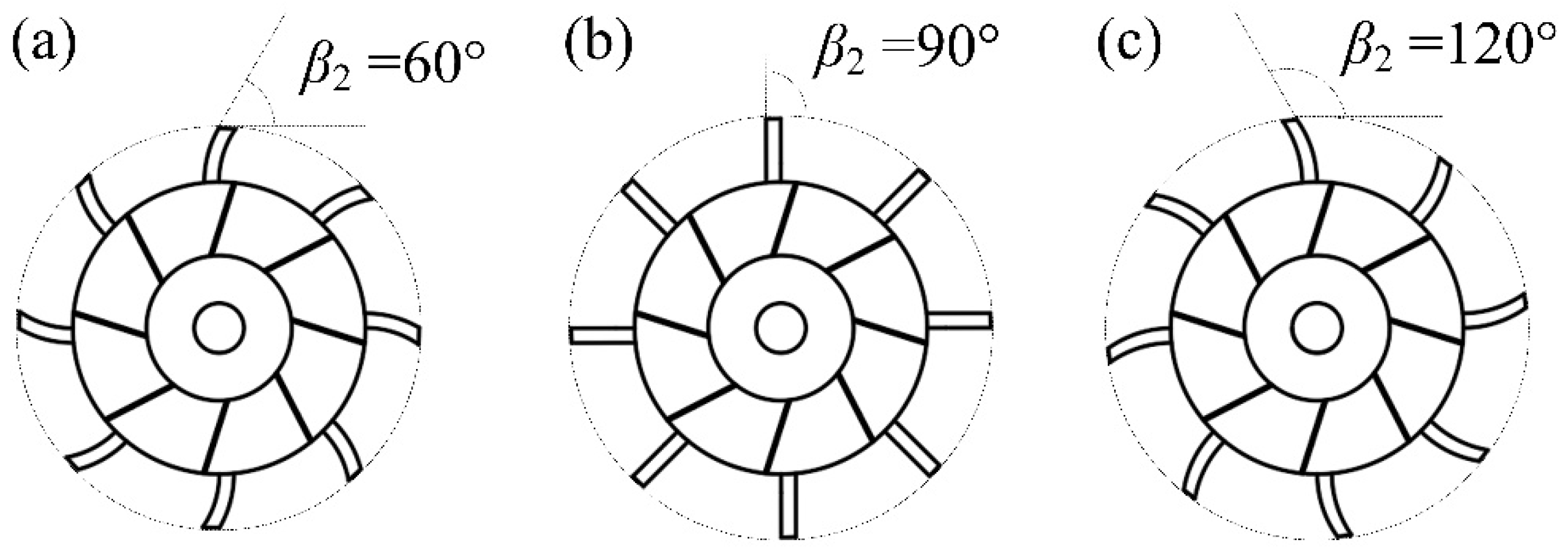
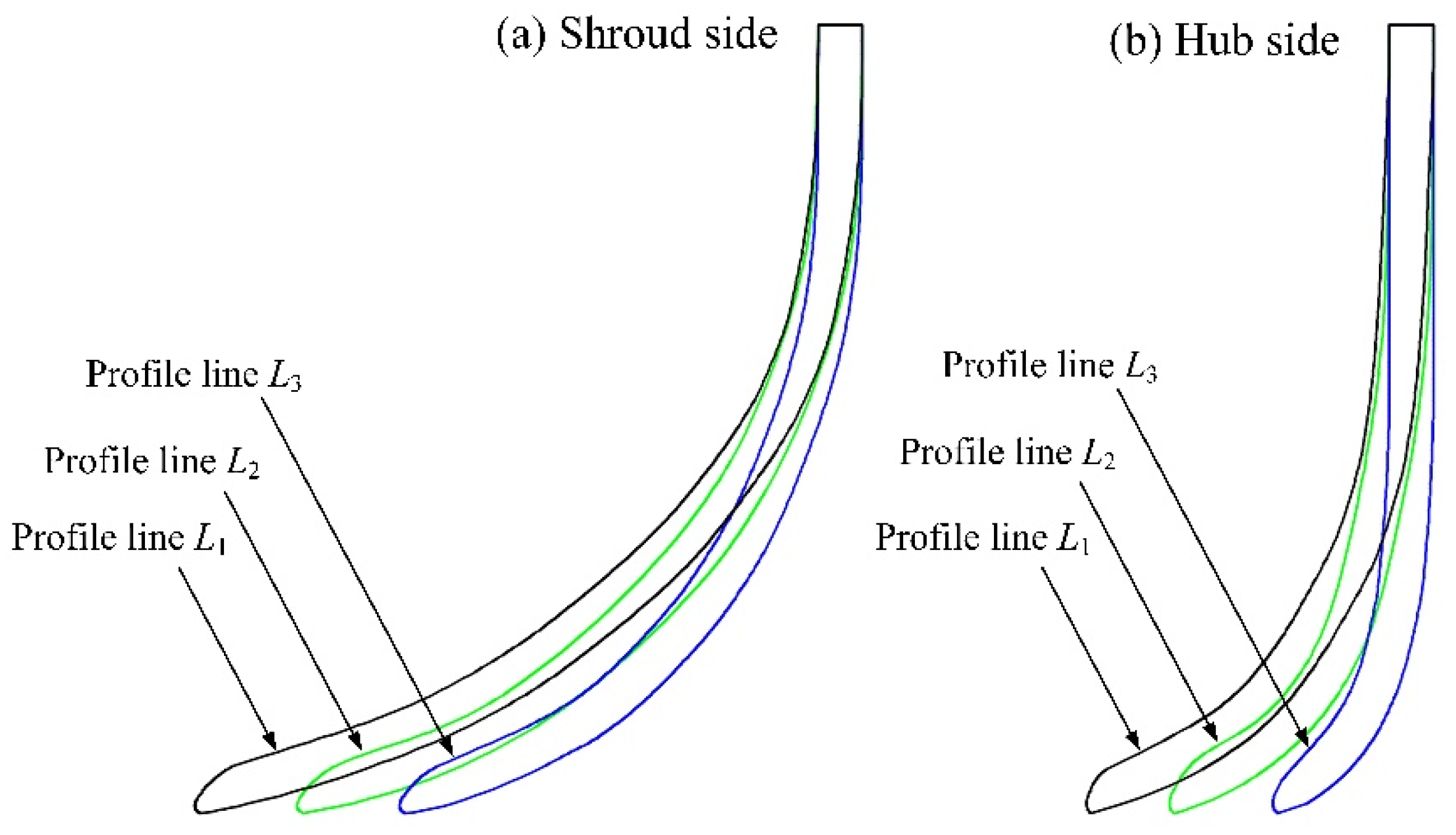
Six geometrical parameters, including key geometric parameters of traditional pumps (i.e., tip diameter of axial cascade D1, impeller outlet diameter D2, and impeller outlet width b2) and some special geometric parameters of this new type of pump (i.e., blade shape of axial cascade named profile line L, hub cover height h, and setting the angle of blade outlet β2 affecting the passive rotational speed of volute), were selected as the test factors to optimize. Orthogonal tests show that the main factors affecting the pump head and efficiency were impeller outlet diameter D2 and profile line L.
(2)
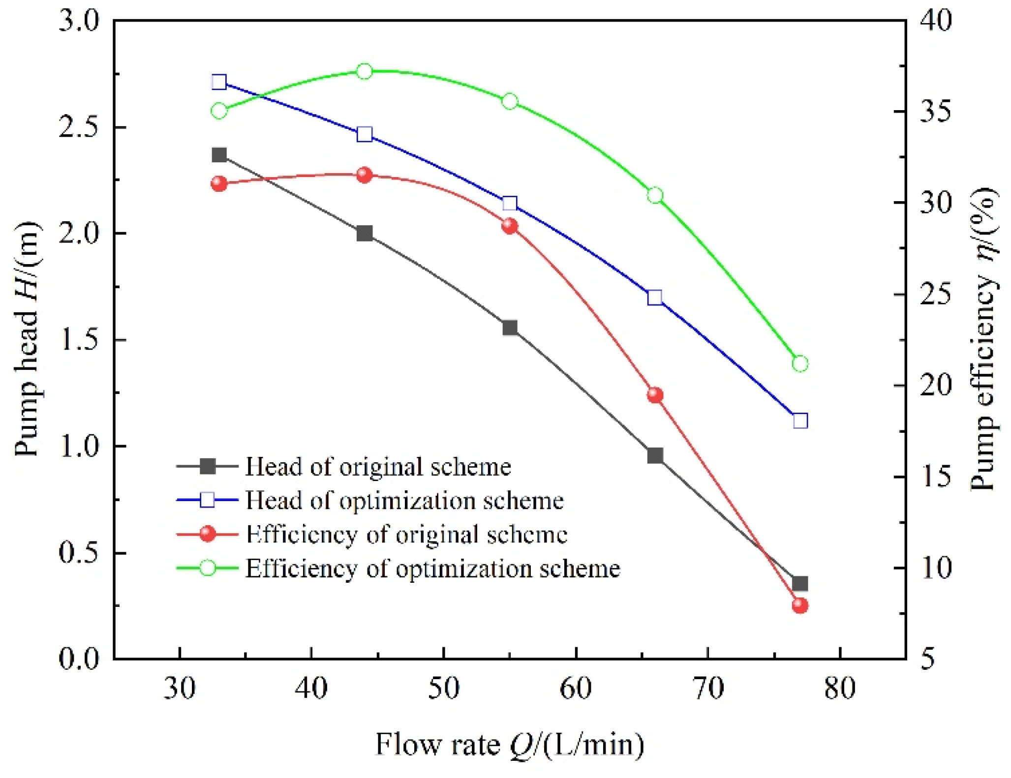
A specially designed test bench under the assumption of static-volute conditions was built to solve the difficult problem of the new pump without a pipeline system and its volute rotation to obtain hydraulic performances. By comparing the results of the original scheme, direct analysis, and range analysis, the scheme obtained by the range analysis was used to optimize the compound impeller, which yielded an increase of 0.3 m in the pump head and 2.99% in the pump efficiency under the rated condition.
(3)
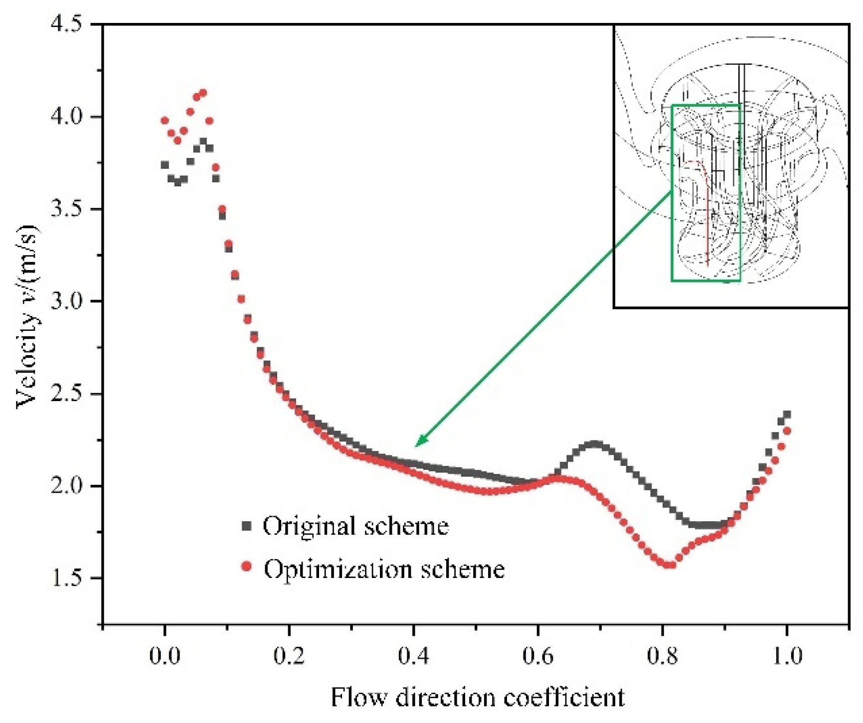
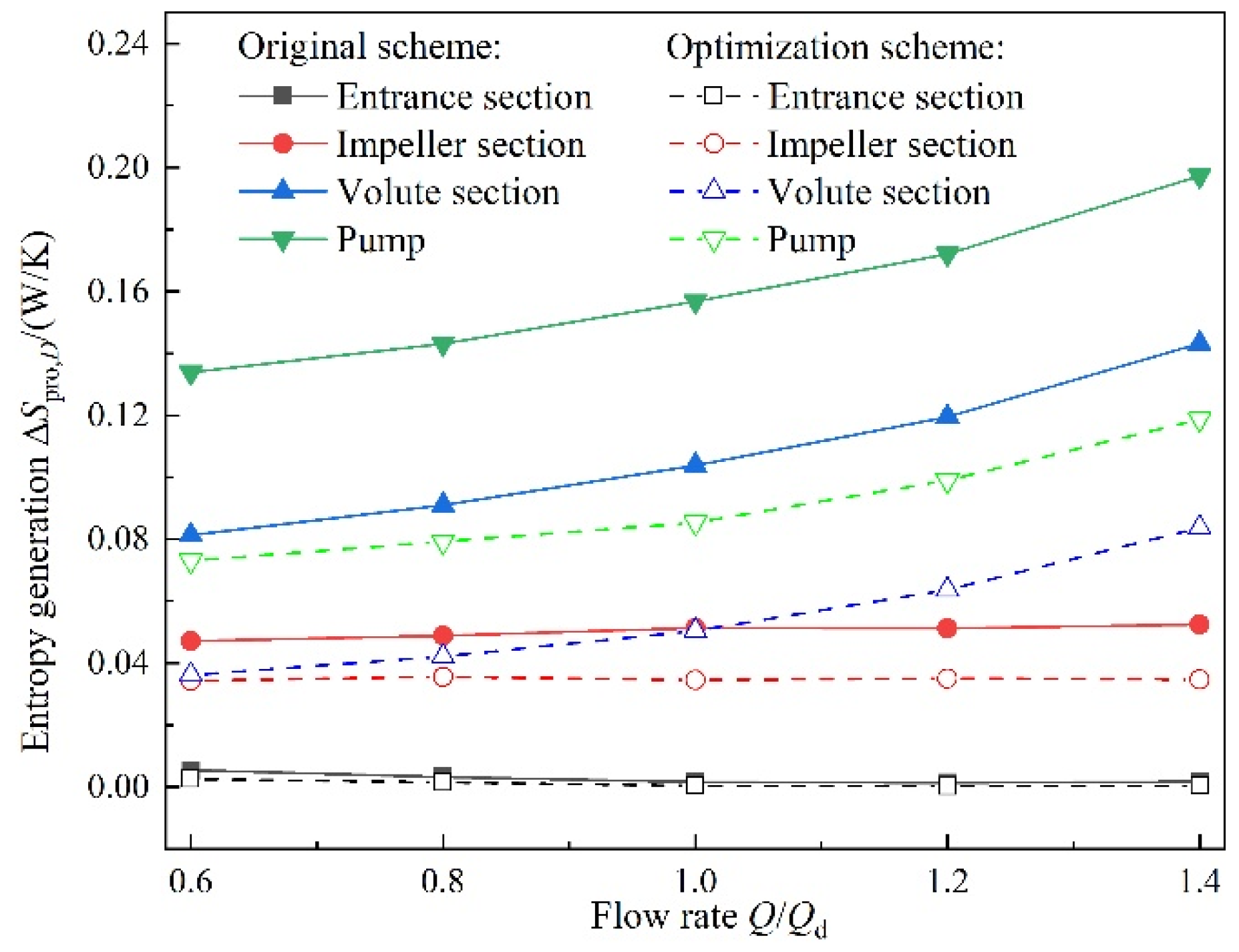
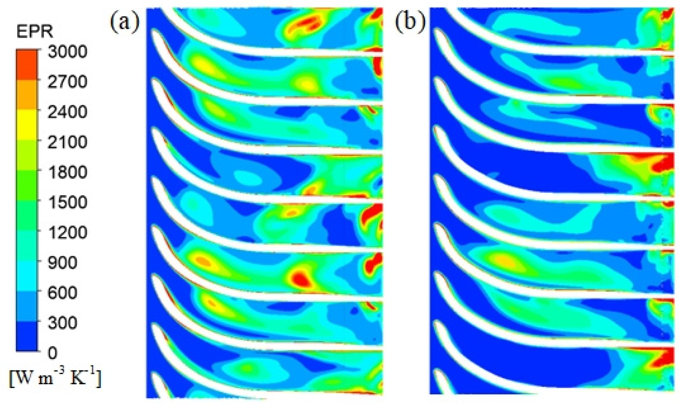
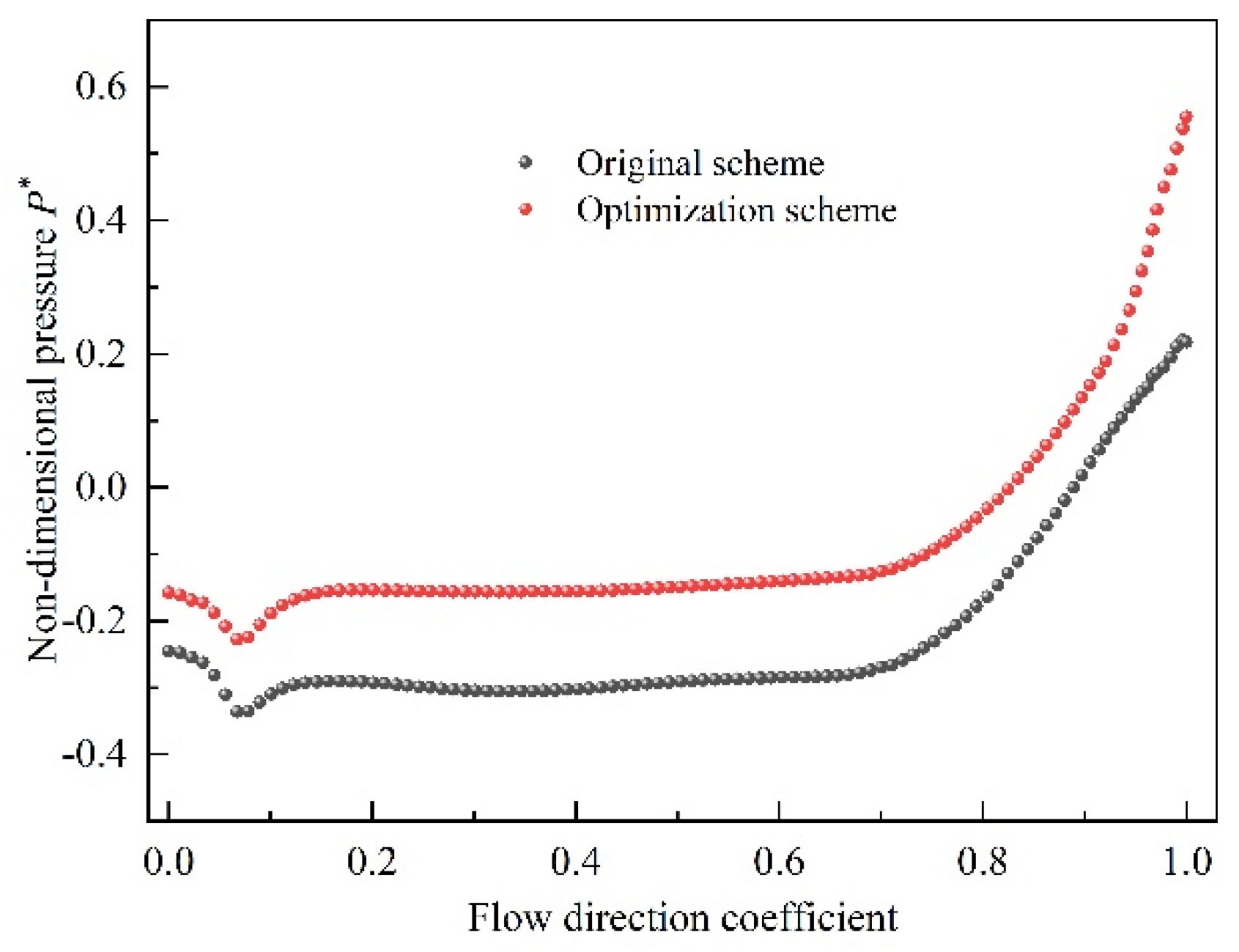
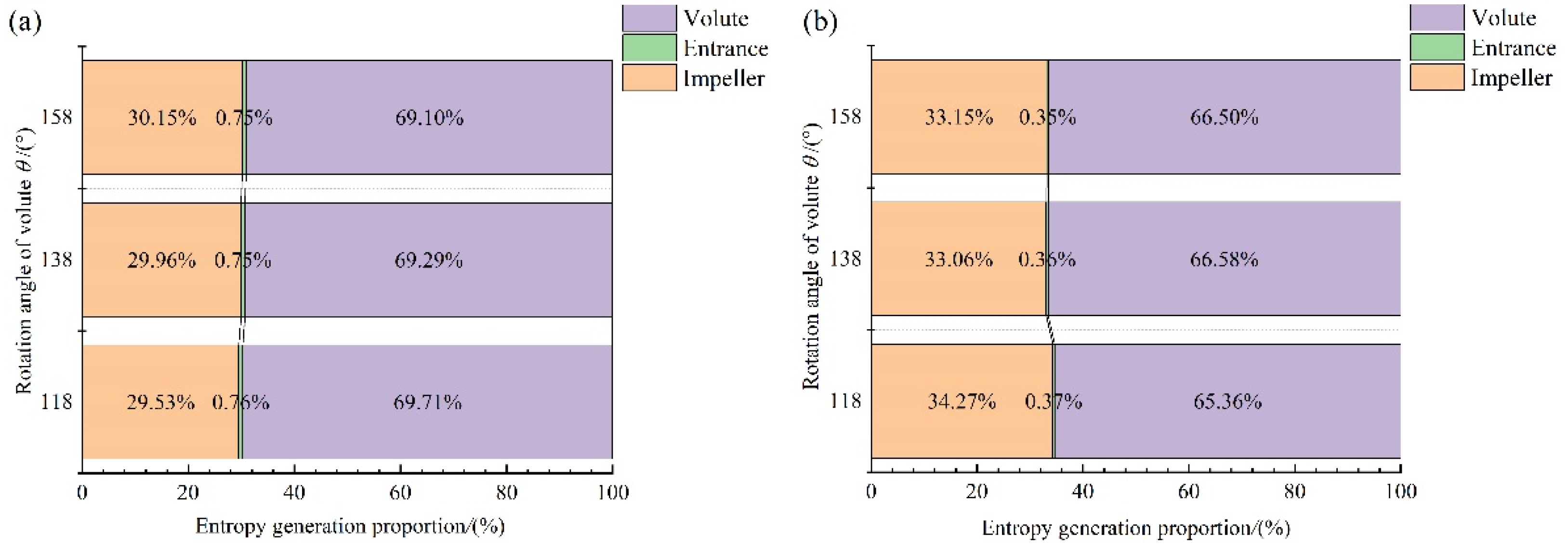
Steady numerical simulations confirmed that the pump head and efficiency after optimization were significantly higher than that of the original scheme for all cases under the static-volute condition. After optimization, the internal pump pressure coefficient became considerably higher. Meanwhile, the flow uniformity and velocity magnitude in the compound impeller channel was also improved. Based on the entropy production analysis, the highest value of entropy occurred in the volute section, followed by the impeller. It was confirmed that the entropy production in each flow passage component of the new type of dishwasher pump was significantly reduced after optimization.
(4)
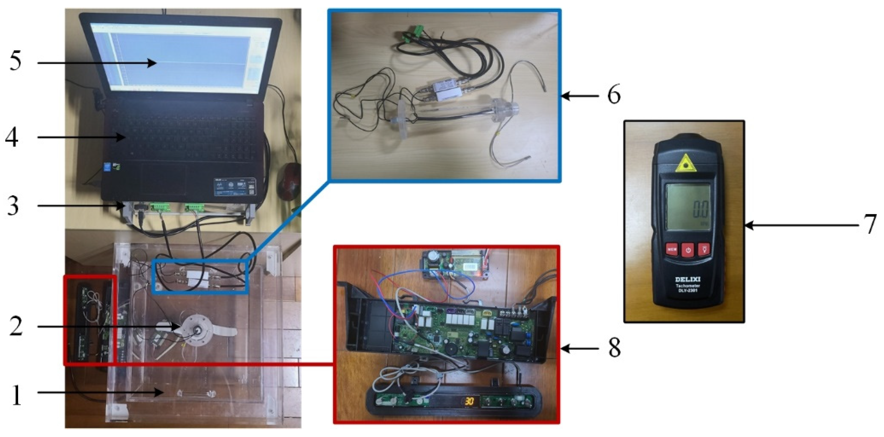
A specially design test (real machine test) bench for the new type of dishwasher pump was firstly built to obtain the passive rotating speed of the twin-volute, and corresponding test results confirmed that the optimization scheme, for which the passive rotating speed of the twin-volute was increased by 10 rpm as compared to the original design, remained feasible under the rotating-volute (actual operation) condition.
(5)
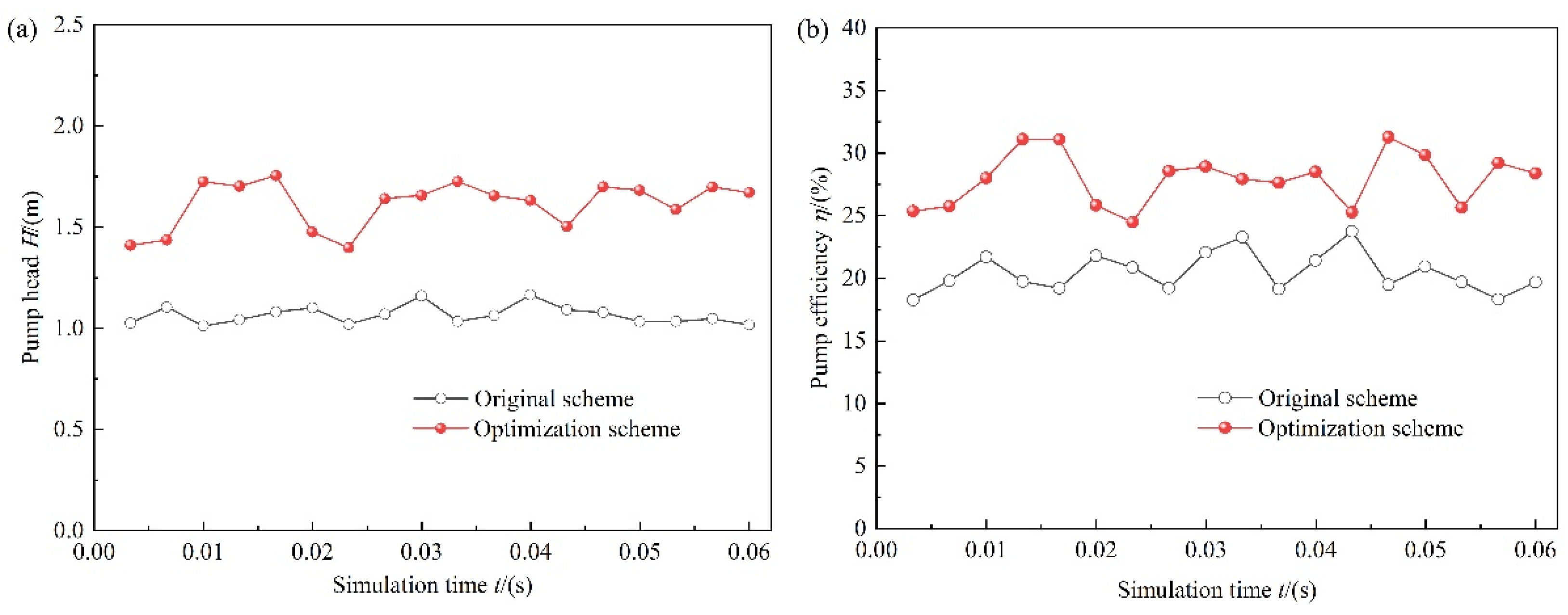
Unsteady numerical simulations confirmed that the pump head was increased by 0.54 m, and the pump efficiency increased by 7.46% after optimization. Meanwhile, the pressure difference between the inlet and outlet of the axial cascade increased, and the low-speed zone in the axial cascade outlet was improved. Based on the entropy production analysis, the volute rotation angles had little effect on the entropy production, but the entropy production at the impeller decreased significantly under the rotating-volute condition. Further, the entropy production of each flow passage component after the optimization was also smaller than that of the original design.
(6)
Based on the results of the hydraulic performance test, steady simulation, real machine test, and unsteady simulation, it was confirmed that the orthogonal optimization test was feasible in the application of the new type of dishwasher pump to solve the problem that the performance of this kind of pump is difficult to measure and optimize. The proposed method and the obtained results herein provide a useful reference for the development of subsequent hydraulic models of dishwasher pumps.

Author Contributions

Conceptualization, Y.L. (Yanjun Li) and H.X.; methodology, Y.L. (Yanjun Li); software, H.S. and Y.L. (Yalin Li); validation, H.X., X.W. and Y.L. (Yalin Li); formal analysis, Y.L. (Yanjun Li); data curation, Y.L. (Yanjun Li); writing—original draft preparation, Y.L. (Yalin Li); writing—review and editing, Y.L. (Yanjun Li), X.W. and Y.L. (Yalin Li) All authors have read and agreed to the published version of the manuscript.

Funding

This research was funded by the Natural Science Foundation of Jiangsu Province (No. BK20180871), the project of the National Natural Science Foundation of China (No. 51809120), the Project Funded by the China Postdoctoral Science Foundation (No. 2018M640462), the Natural Science Foundation of the Jiangsu Higher Education Institutions of China (No. 18KJB470005), and the Priority Academic Program Development of Jiangsu Higher Education Institutions (PAPD).

Conflicts of Interest

The authors declare no conflict of interest.

References

  1. Ning, C.; Li, Y.; Huang, P.; Xu, H.; Zheng, F. Numerical analysis of a new type of dishwasher pump for different rotation speeds of the volute. Front. Energy Res. 2022, 9, 825159. [Google Scholar] [CrossRef]
  2. Ah, R.; Jung, Y.; Jin, H.; Wisam, J.; Han, S. Development of flow visualization technique for analysis of flow distribution inside dishwasher. J. Korean Soc. Vis. 2013, 11, 12–17. [Google Scholar] [CrossRef]
  3. Dedoussis, V.; Giannatsis, J. Stereolithography assisted redesign and optimization of a dishwasher spraying arm. Rapid Prototyp. J. 2004, 10, 255–260. [Google Scholar] [CrossRef]
  4. Santori, G.; Frazzica, A.; Freni, A.; Galieni, M.; Bonaccorsi, L.; Polonara, F.; Restuccia, G. Optimization and testing on an adsorption dishwasher. Energy 2013, 50, 170–176. [Google Scholar] [CrossRef]
  5. Pérez-Mohedano, R.; Letzelter, N.; Amador, C.; Vanderroest, C.; Bakalis, S. Positron emission particle tracking (PEPT) for the analysis of water motion in a domestic dishwasher. Chem. Eng. J. 2015, 259, 724–736. [Google Scholar] [CrossRef]
  6. Pérez-Mohedano, R.; Letzelter, N.; Bakalis, S. Integrated model for the prediction of cleaning profiles inside an automatic dishwasher. J. Food Eng. 2017, 196, 101–112. [Google Scholar] [CrossRef]
  7. Minde, M. Validation of Dishwasher CFD Model Using PIV. Master Thesis, Lulea University of Technology, Lulea, Sweden, 2016. [Google Scholar]
  8. Zhang, F.; Fleder, A.; Bohle, M.; Yuan, S. Effect of suction side blade profile on the performance of a side channel pump. Proceedings of the Institution of Mechanical Engineers, Part, A.J. Power Energy 2016, 230, 586–597. [Google Scholar] [CrossRef]
  9. Cui, B.; Wang, C.; Zhu, Z.; Jin, Y. Influence of blade outlet angle on performance of low-specific-speed centrifugal pump. J. Therm. Sci. 2013, 22, 117–122. [Google Scholar] [CrossRef]
  10. Fu, D.; Wang, F.; Zhou, P.; Xiao, R.; Yao, Z. Impact of impeller stagger angles on pressure fluctuation for a double-suction centrifugal pump. Chin. J. Mech. Eng. 2018, 31, 198–211. [Google Scholar] [CrossRef]
  11. Sanjay, V.; Abhishek, S.; Karan, H.; Patel, R. Effects of impeller diameter and rotational speed on performance of pump running in turbine mode. Energy Convers. Manag. 2015, 89, 808–824. [Google Scholar] [CrossRef]
  12. Mohammad, H.; Salman, S. Effects of impeller geometry modification on performance of pump as turbine in the urban water distribution network. Energy 2022, 255, 124550. [Google Scholar] [CrossRef]
  13. Zeynel, A.; Mustafa, N. Investigation of the effect of the stages Number, the impeller outlet width, and the impeller outlet angle on the performance of an industrial electric submersible pump. J. Fluids Eng. 2022, 144, 081203. [Google Scholar] [CrossRef]
  14. Wang, W.; Tai, G.; Pei, J.; Pavesi, G.; Yuan, S. Numerical investigation of the effect of the closure law of wicket gates on the transient characteristics of pump-turbine in pump mode. Renew. Energy 2022, 194, 719–733. [Google Scholar] [CrossRef]
  15. Zhu, Y.; Zhang, J.; Li, Y.; Huang, P.; Xu, H.; Zheng, F. Experimental investigation of unsteady pressure pulsation in new type dishwasher pump with special double-tongue volute. Machines 2021, 9, 288. [Google Scholar] [CrossRef]
  16. Zhang, J.; Zhu, Y.; Li, Y.; Huang, P.; Xu, H.; Zheng, F. Investigation of unsteady pressure pulsation in new type dishwasher pump with special double tongue volute. Shock. Vib. 2022, 2022, 9349432. [Google Scholar] [CrossRef]
  17. Thakkar, S.; Vala, H.; Patel, V.; Patel, R. Performance improvement of the sanitary centrifugal pump through an integrated approach based on response surface methodology, multi-objective optimization and CFD. J. Braz. Soc. Mech. Sci. Eng. 2021, 43, 24. [Google Scholar] [CrossRef]
  18. Shim, H.S.; Kim, K.Y. Design optimization of the impeller and volute of a centrifugal pump to improve the hydraulic performance and flow stability. J. Fluids Eng. 2020, 142, 101211. [Google Scholar] [CrossRef]
  19. Xu, Y.; Tan, L.; Cao, S.; Qu, W. Multiparameter and multi-objective optimization design of centrifugal pump based on orthogonal method. Proc. Inst. Mech. Eng. Part C J. Mech. Eng. Sci. 2017, 231, 2569–2579. [Google Scholar] [CrossRef]
  20. Zhao, F.; Kong, F.; Zhou, Y.; Xia, B.; Bai, Y. Optimization design of the impeller based on orthogonal test in an ultra-low specific speed magnetic drive pump. Energies 2019, 12, 4767. [Google Scholar] [CrossRef]
  21. Quan, H.; Guo, Y.; Li, R.; Su, Q.; Chai, Y. Optimization design and experimental study of vortex pump based on orthogonal test. Sci. Prog. 2019, 103, 003685041988188. [Google Scholar] [CrossRef] [Green Version]
  22. Yang, Y.; Zhou, L.; Zhou, H.; Lv, W.; Wang, J.; Shi, W.; He, Z. Optimal design of slit impeller for low specific speed centrifugal pump based on orthogonal test. J. Mar. Sci. Eng. 2021, 9, 121. [Google Scholar] [CrossRef]
  23. Li, Z.; Ding, H.; Shen, X.; Jian, Y. Performance optimization of high specific speed centrifugal pump based on orthogonal experiment design method. Processes 2019, 7, 728. [Google Scholar] [CrossRef]
  24. Li, D.; Wang, H.; Qin, Y.; Han, L.; Wei, X.; Qin, D. Entropy production analysis of hysteresis characteristic of a pump-turbine model. Energy Convers. Manag. 2017, 149, 175–191. [Google Scholar] [CrossRef]
  25. Behzadmehr, A.; Mercadier, Y. Numerical study of flow parameters and entropy generation on a centrifugal fan. Int. J. Exergy 2009, 6, 80–92. [Google Scholar] [CrossRef]
  26. Tang, X.; Jiang, W.; Li, Q.; Hou, G.; Ning, Z.; Wang, Y.; Chen, D. Analysis of hydraulic loss of the centrifugal pump as turbine based on internal flow feature and entropy generation theory. Sustain. Energy Technol. Assess. 2022, 52, 102070. [Google Scholar] [CrossRef]
  27. Ji, L.; Li, W.; Shi, W.; Tian, F.; Agarwal, R. Diagnosis of internal energy characteristics of mixed-flow pump within stall region based on entropy production analysis model. Int. Commun. Heat Mass Transf. 2020, 117, 104784. [Google Scholar] [CrossRef]
  28. Kock, F.; Herwig, H. Local entropy production in turbulent shear flows: A high-Reynolds number model with wall functions. Int. J. Heat Mass Transf. 2004, 47, 2205–2215. [Google Scholar] [CrossRef]
  29. Ghasemi, E.; Mceligot, D.; Nolan, K.; Crepeau, J.; Tokuhiro, A.; Budwig, R. Entropy generation in a transitional boundary layer region under the influence of freestream turbulence using transitional RANS models and DNS. Int. Commun. Heat Mass Transf. 2013, 41, 10–16. [Google Scholar] [CrossRef]
  30. Mceligot, D.; Nolan, K.; Walsh, E.; Laurien, E. Effects of pressure gradients on entropy generation in the viscous layers of turbulent wall flows. Int. J. Heat Mass Transf. 2008, 51, 1104–1114. [Google Scholar] [CrossRef]
Figure 1. Comparison of the new sink-type dishwasher with innovative pump and traditional dishwasher. I: schematic diagram of spray and pipeline system of traditional dishwasher, II: a new type of dishwasher pump, III: twin-volute spray arm, IV: computational domain of new type of dishwasher pump. 1: new sink-type dishwasher, 2: traditional dishwasher, 3: pipeline system, 4: traditional spray arm, 5: twin-volute, 6: compound impeller, 7: entrance section, 8: DC motor, 9: nozzle, 10: basic circle of volute, 11: profile of flow channel of twin-volute, 12: impeller active rotation, 13: volute passive rotation.
Processes 10 01813 g001
Figure 2. Geometry parameters of the compound impeller.
Processes 10 01813 g002
Figure 3. Schematic diagram of the setting angle of blade outlet β2. (a): β2 = 60°, (b): β2 = 90°, and (c): β2 = 120°.
Processes 10 01813 g003
Figure 4. Schematic diagram of the profile line L of the axial cascade. (a): profile line L on the shroud side and (b): on the hub side.
Processes 10 01813 g004
Figure 5. Photos of all the 18 impeller models, where schemes represented by 1~18 are detailly listed in Table 2.
Processes 10 01813 g005
Figure 6. Hydraulic performance test bench for the new type of dishwasher pump. 1: motor speed controller, 2: computer, 3: data-acquisition system, 4: water tank, 5: electromagnetic valve, 6: turbine flowmeter, 7: outflow pipe, 8: pressure gauge, 9: inlet pipe, 10: dishwasher pump, and 11: torsiograph.
Processes 10 01813 g006
Figure 7. Column figure of orthogonal test results.
Processes 10 01813 g007
Figure 8. Relationship between factors and performance indicators: (a) pump head and (b) pump efficiency.
Processes 10 01813 g008
Figure 9. Optimal impeller scheme obtained by range analysis.
Processes 10 01813 g009
Figure 10. Hydraulic performance of the new type of dishwasher pump before and after optimization.
Processes 10 01813 g010
Figure 11. Streamline distribution of radial blades of compound impeller before and after optimization: (a) original scheme and (b) optimization scheme.
Processes 10 01813 g011
Figure 12. Distribution of average velocity from compound impeller inlet to outlet before and after optimization.
Processes 10 01813 g012
Figure 13. Components of entropy production and total entropy production in each flow passage.
Processes 10 01813 g013
Figure 14. Proportion of entropy production of each flow passage component: (a) original scheme and (b) optimization scheme.
Processes 10 01813 g014
Figure 15. Distribution of local entropy production in the axial cascades: (a) original scheme and (b) optimization scheme.
Processes 10 01813 g015
Figure 16. New type of dishwasher pump, real test bench. 1: water tank, 2: dishwasher pump. 3: data-acquisition system, 4: computer. 5: software interface, 6: rotating pressure pulsation test device, 7: tachometer, and 8: motor speed controller.
Processes 10 01813 g016
Figure 17. Unsteady hydraulic performance curves of the last three cycles under rated conditions: (a) pump head and (b) pump efficiency.
Processes 10 01813 g017
Figure 18. Time-averaged pressure coefficient distribution curve from inlet to outlet of compound impeller before and after optimization under the rated condition.
Processes 10 01813 g018
Figure 19. Time-averaged pressure coefficient distribution at 0.8 times blade height (a) and time-averaged velocity distribution at 0.5 times blade height (b) in impeller passage before and after optimization.
Processes 10 01813 g019
Figure 20. Distribution of entropy production and total entropy production of each flow passage component.
Processes 10 01813 g020
Figure 21. Proportion of entropy production of each flow passage component: (a) original scheme and (b) optimization scheme.
Processes 10 01813 g021
Table 1. Factor level table.
LevelFactor
ABCDEF
LD1/mmD2/mmb2/mmh/mmβ2
113041121360
223243141490
3334451615120
Table 2. Orthogonal test table.
Scheme No.Factor SymbolFactor Value
ABCDEFA
(-)
B
(mm)
C
(mm)
D
(mm)
E
(mm)
F
(°)
1A1B1C1D1E1F113041121360
2A1B1C2D2E3F3130431415120
3A1B2C1D3E3F213241161590
4A1B2C3D1E2F3132451214120
5A1B3C2D3E2F113443161460
6A1B3C3D2E1F213445141390
7A2B1C1D3E2F3230411614120
8A2B1C3D1E3F223045121590
9A2B2C2D2E2F223243141490
10A2B2C3D3E1F123245161360
11A2B3C1D2E3F123441141560
12A2B3C2D1E1F3234431213120
13A3B1C2D3E1F233043161390
14A3B1C3D2E2F133045141460
15A3B2C1D2E1F3332411413120
16A3B2C2D1E3F133243121560
17A3B3C1D1E2F233441121490
18A3B3C3D3E3F3334451615120
Table 3. Range analysis of pump head.
Performance IndexFactor
ABCDEF
H/mK111.93412.56910.81112.29812.56411.748
K213.2112.90112.93712.90113.03812.847
K313.0212.69414.41612.96512.56213.569
k11.9892.0951.8022.052.0941.958
k22.2022.152.1562.152.1732.141
k32.172.1162.4032.1612.0942.262
RangeRH0.2130.0550.6010.1110.0790.304
Table 4. Range analysis of pump efficiency.
Performance IndexFactor
ABCDEF
η/%K1234.849251.114240.208240.183248.412250.752
K2261.451255.466257.037252.569257.208252.671
K3258.982248.702258.037262.53249.662251.859
k139.14241.85240.03540.03141.40241.792
k243.57542.57842.8442.09542.86842.112
k343.16441.4543.00643.75541.6141.977
RangeRη4.4331.1282.9713.7241.4660.32
Table 5. Comparison of the original and optimization schemes.
Original SchemeScheme by Direct AnalysisScheme by Range Analysis
H/m2.242.362.54
η/%42.5245.4445.51
Publisher’s Note: MDPI stays neutral with regard to jurisdictional claims in published maps and institutional affiliations.

