
Case Study: Successful Application of a Novel Gas Lift Valve in Low Pressure Wells in Fuling Shale Gas Field

Abstract
:1. Introduction
2. Gas Lift Valves
- The pressure control components are made of three layers of monel alloy and the test rack opening pressure is very sensitive to low pressure, thus it meets the accuracy of low-pressure well activation.
- The new type of gas lift valve can connect/disconnect the first and second through-hole of the internal structure of the air lift valve by installing a hydraulic piston that can move axially inside the valve body. This technology connects the space of the annulus and tubing by injecting liquid inside the tubing to activate the gas lift valve, thus it greatly reduces the operation frequency of replacing the dummy valve and as a result reduces the cost and risks and saves time.
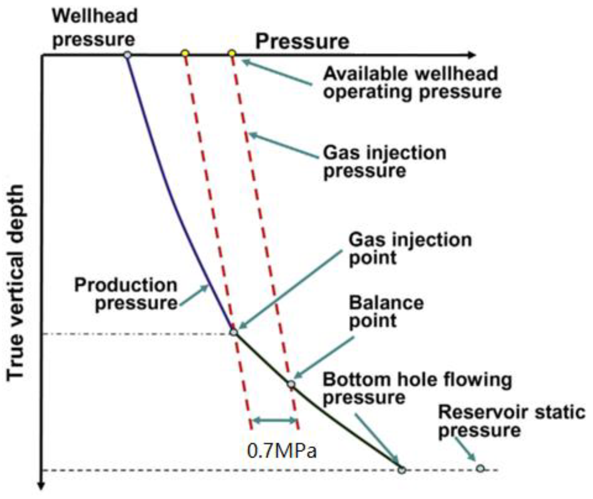
- The most import function of this new type of valve can greatly reduce the required gas lift pressure to the level of piping line pressure which is approximately around 5 MPa. By utilizing piping line pressure, the gas wells’ production can be restored instantaneously after a hydraulic fracturing operation or being heavily water-loaded.
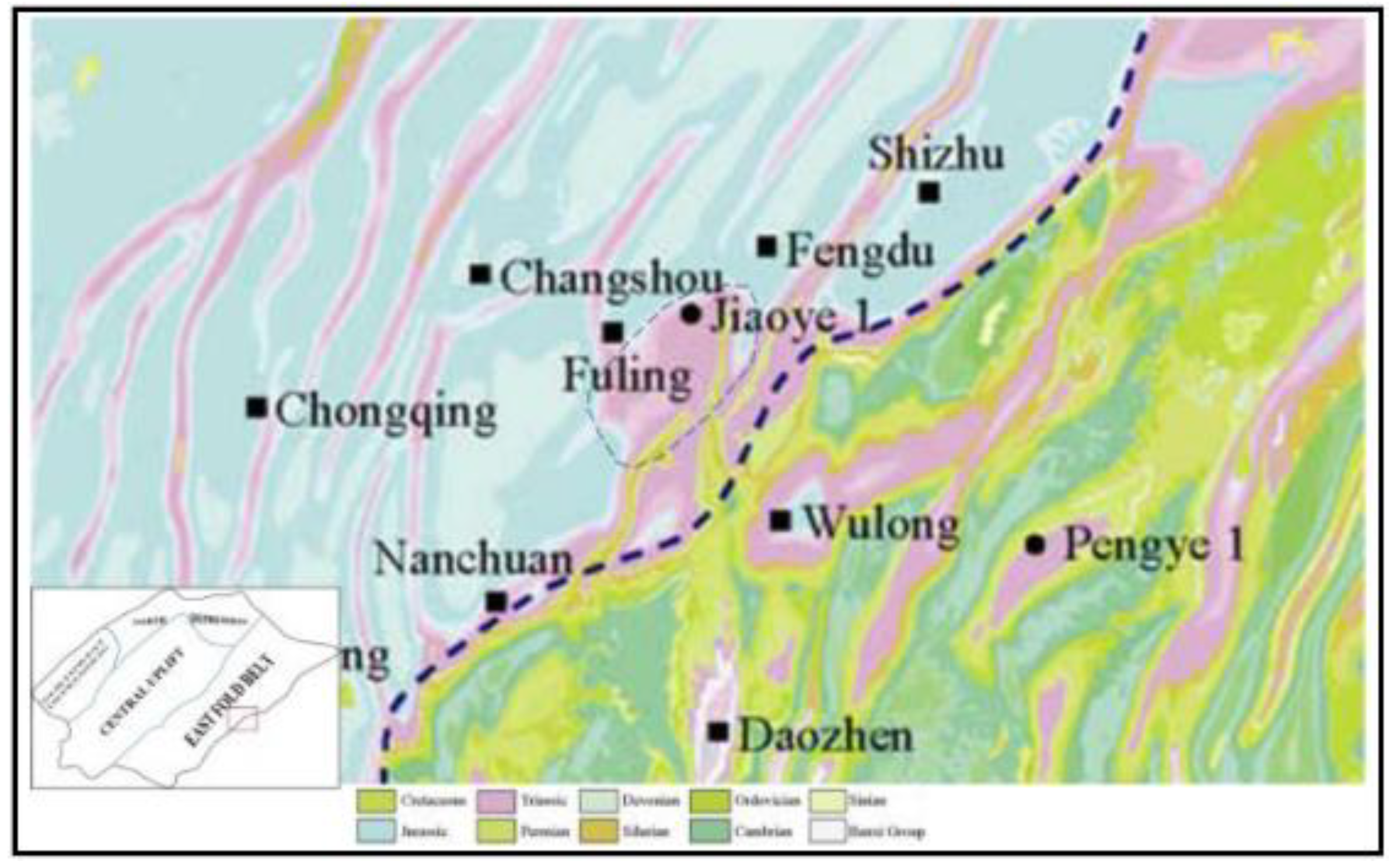
3. Geological Overview
4. Candidates Selection
5. Project Validation
5.1. Unloading
5.2. Field Trail Result and Data Validation
6. Conclusions
Author Contributions
Funding
Institutional Review Board Statement
Informed Consent Statement
Data Availability Statement
Conflicts of Interest
References
- Tingxue, J.; Dehua, Z.; Changgui, J.; Haitao, W.; Xiaobing, B.; Shuangming, L.; Xiaobo, X.; Weiran, W.; Suyuan, S. The Study and Application of Multi-Stage Fracturing Technology of Horizontal Wells to Maximize ESRV in the Exploration & Development of Fuling Shale gas Play, Chongqing, China. In Proceedings of the SPE Asia Pacific Hydraulic Fracturing Conference, Beijing, China, 24–26 August 2016; Available online: https://onepetro.org/speaphf/proceedings/16APHF/2-16APHF/Beijing,%20China/185205 (accessed on 2 November 2022).
- Yaowen, L.; Yuanzhao, L.; Chi, Z.; Yue, M.; Jialin, X.; Rong, H.; Zichao, W.; Jiao, Z.; Wu, C. First Successful Application of Casing in Casing CiC Refracturing Treatment in Shale Gas Well in China: Case Study. In Proceedings of the Abu Dhabi International Petroleum Exhibition & Conference, Abu Dhabi, United Arab Emirates, 15–18 November 2021; Available online: https://onepetro.org/SPEADIP/proceedings/21ADIP/1-21ADIP/D011S006R002/473700 (accessed on 2 November 2022).
- Guo, T.; Li, J.; Lao, M.; Li, W. Integrated Geophysical Technologies for Unconventional Reservoirs and Case Study within Fuling Shale Gas Field, Sichuan Basin, China. In Proceedings of the Unconventional Resources Technology Conference, San Antonio, TX, USA, 20–22 July 2015; p. 10. [Google Scholar]
- Zhang, L. Application and Prospect of Gas Lift Technology with Gas Lift Valves in Fuling Shale Gas Field. J. Jianghan Pet. Univ. Staff. Work. 2022, 35, 20–21, 60. [Google Scholar]
- Di, D.; Pang, W.; Mao, J.; Ai, S.; Ying, H. Production Logging Application in Fuling Shale Gas Play in China. In Proceedings of the SPE Asia Pacific Oil & Gas Conference and Exhibition, Perth, Australia, 25–27 October 2016; Available online: https://onepetro.org/SPEAPOG/proceedings/16APOG/All-16APOG/Perth,%20Australia/185405 (accessed on 5 November 2022).
- Wei, P.; Zuqing, H.; Cuiping, X.; Juan, D.; Sun, Z. SRV Analysis of Shale Gas Wells in China. In Proceedings of the SPE Asia Pacific Unconventional Resources Conference and Exhibition, Brisbane, Australia, 9–11 November 2015; Available online: https://onepetro.org/SPEURCE/proceedings/15URCE/All-15URCE/Brisbane,%20Australia/183964 (accessed on 5 November 2022).
- Demoss, E.E.; Ellis, R.C.; Kingsley, G.S. New Gas-Lift Concept-Continuous-Flow Production Rates from Deep, Low-Pressure Wells. J. Pet. Technol. 1974, 26, 13–18. [Google Scholar] [CrossRef]
- Azizollah, K.; Petrakov, D.G.; Benson, L.A.B.; Rastegar, R.A. Prevention of Calcium Carbonate Precipitation during Water Injection into High-Pressure High-Temperature Wells. In Proceedings of the SPE European Formation Damage Conference and Exhibition, Budapest, Hungary, 3–5 June 2015; Available online: https://onepetro.org/SPEEFDC/proceedings/15EFDC/All-15EFDC/Budapest,%20Hungary/183005 (accessed on 5 November 2022).
- Wang, Y.; Tian, Z.; Yang, L.; Yan, X.; Yi, X.; Lu, H.; Yaoyao, D. What We Have Learned on Shale Gas Fracturing During the Past Five Years in China. In Proceedings of the SPE Asia Pacific Oil & Gas Conference and Exhibition, Perth, Australia, 25–27 October 2016; Available online: https://onepetro.org/SPEAPOG/proceedings/16APOG/All-16APOG/Perth,%20Australia/185283 (accessed on 11 November 2022).
- Priscilla, E.; Ademola, A.; Oluwafemi, O.; Nchekwube, L.; Emmanuel, M.; Fred, O.; Fatoke, O. Evaluating Alternate Artificial Lift Methods in the Niger Delta. In Proceedings of the SPE Nigeria Annual International Conference and Exhibition, Lagos, Nigeria, 2–4 August 2021; Available online: https://onepetro.org/SPENAIC/proceedings/21NAIC/3-21NAIC/D031S019R005/465696 (accessed on 11 November 2022).
- Wei, P.; Qiong, W.; Ying, H.; Juan, D.; Tongyi, Z.; Christine, A. Production Analysis of One Shale Gas Reservoir in China. In Proceedings of the SPE Annual Technical Conference and Exhibition, Houston, TX, USA, 28–30 September 2015; Available online: https://onepetro.org/SPEATCE/proceedings/15ATCE/2-15ATCE/Houston,%20Texas,%20USA/180473 (accessed on 11 November 2022).


| Comparison | Selection Criteria | SRP | PCP | ESP | Jet Pump | GL |
|---|---|---|---|---|---|---|
| System Condition | System Complexity | Simple | Simple | Downhole Complex | Surface Complex | Surface Complex |
| Initial Investment | Low | Low | High | High | Highest | |
| Operation Cost | Low | Low | High | Low | Low | |
| Fluid Range, | Fluid Rate Range | 1–100 | 10–200 | 80–700 | 10–500 | 30–3180 |
| m3/d | Maximum Range | 300 | 250 | 1400 | 1590 | −7945 |
| Lifting Depth, m | Lifting Depth | <3000 | <1500 | <2000 | <2000 | <4000 |
| Maximum Depth | 4421 | 1700 | 3084 | 3500 | 4500 | |
| Downhole Condition | Small Tubing Size | Not Applicable | Not Applicable | Not Applicable | Not Applicable | Not Applicable |
| Multiple Layer Production | Not Applicable | Not Applicable | Applicable | Applicable | Applicable | |
| Slanted Well | Normal Wear | Normal Wear | Applicable | Applicable | Applicable | |
| Degree of Hollowing Out | High | Very High | High | Very High | High | |
| Surface Condition | Offshore | Not Applicable | Very Applicable | Applicable | Applicable | Very Applicable |
| Remote Area | Normal | Normal | Applicable | Applicable | Applicable | |
| Operation | High GOR | Very Applicable | Normal | Not Applicable | Applicable | Very Applicable |
| Heavy Oil | Applicable | Applicable | Not Applicable | Very Applicable | Not Applicable | |
| Sand Production | Very Applicable | Applicable | Not Applicable | Applicable | Very Applicable | |
| Corrosion | Applicable | Applicable | Applicable | Applicable | Applicable | |
| Scale | Applicable | Not Applicable | Not Applicable | Applicable | Applicable | |
| Adjust Working System | Convenient | Convenient | Not Convenient | Convenient | Convenient | |
| Power Supply | Electricity, Oil, NG | Electricity, Oil, NG | Electricity | Electricity, Oil, NG | Electricity, Oil, NG | |
| Power Medium Requirements | None | None | None | Hydrodynamic Fluid | Anti-hydrate | |
| Maintenance Management | Pump Inspection | Tubing WO | Tubing WO | Tubing WO | Slickline Ops | Slickline Ops |
| Avg. WO Period, a | 2 | 1 | 1.5 | 0.5 | 3 | |
| Auto-control | Applicable | Applicable | Applicable | Applicable | Applicable |
| Series No. | Well Name | Tubing Size, mm | Casing Size, mm | Well Depth (MD), m | Piping Line Pressure, MPa | Tubing Setting Depth, m | New Tied in Well |
|---|---|---|---|---|---|---|---|
| 1 | FL-1HF | 48.26 | 139.70 | 4576 | 5.5 | 3067 | N |
| 2 | FL-2HF | 48.26 | 139.70 | 4157 | 6.5 | 2620 | Y |
| 3 | FL-3HF | 48.26 | 139.70 | 5176 | 6.0 | 3564 | Y |
| 4 | FL-4HF | 48.26 | 139.70 | 4840 | 6.1 | 3277 | N |
| 5 | FL-5HF | 48.26 | 139.70 | 4840 | 6.3 | 3212 | N |
| 6 | FL-6HF | 48.26 | 139.70 | 5335 | 5.9 | 3527 | N |
| 7 | FL-7HF | 48.26 | 139.70 | 4471 | 5.7 | 2977 | N |
| 8 | FL-8HF | 48.26 | 139.70 | 4640 | 5.9 | 2506 | Y |
| 9 | FL-9HF | 48.26 | 139.70 | 4545 | 6.7 | 2976 | N |
| 10 | FL-10HF | 60.33 | 139.70 | 4324 | 6.2 | 2568 | N |
| 11 | FL-11HF | 48.26 | 139.70 | 4341 | 6.1 | 2717 | Y |
| 12 | FL-12HF | 48.26 | 139.70 | 4966 | 6.5 | 3452 | Y |
| 13 | FL-13HF | 48.26 | 139.70 | 5030 | 6.1 | 3248 | Y |
| Type | SKY-GLV-18.8 |
|---|---|
| OD, mm | 18.8 |
| Length, mm | 300 |
| Effective area of bellows, sq. mm | 110 |
| Connection Thread | 1/4 NPT |
| Pressure Rating, MPa | 50 |
| Valve hole size, mm | 3.17, 4.76 |
| Kick off Pressure: 15 MPa Operating Pressure: 5.5 MPa Injecting Gas Rate: 0.8 10 kscm/d | ||||||||
|---|---|---|---|---|---|---|---|---|
| Stages | Setting Depth (MD), m | Setting Depth (TVD), m | Inclination Angle, ° | Valve Hole Size, mm | Pro, MPa | Pv-Open, MPa | Pv-Close, MPa | Mandrel Type |
| 1 | 470.18 | 470.13 | 0.6 | 3.2 | 5.032 | 5.098 | 4.954 | SKY-FGLM-90 |
| 2 | 907.39 | 907.29 | 0.8 | 3.2 | 4.602 | 4.975 | 4.851 | SKY-FGLM-90 |
| 3 | 1294 | 1293.9 | 0.7 | 3.2 | 4.382 | 4.852 | 4.747 | SKY-FGLM-90 |
| 4 | 1629.6 | 1629.4 | 0.4 | 3.2 | 4.193 | 4.73 | 4.644 | SKY-FGLM-90 |
| 5 | 1913.3 | 1913.1 | 6 | 3.2 | 4.037 | 4.61 | 4.541 | SKY-FGLM-90 |
| 6 | 2157 | 2146.7 | 32.2 | 3.2 | 3.913 | 4.492 | 4.437 | SKY-FGLM-90 |
| Well Name | Lifted Liquid Volume, scm | Gas Rate before GL Operation, 10 kscm /d | Gas Rate after GL Operation, 10 kscm/d | Incremental of Gas Rate, 10 kscm /d | Remarks |
|---|---|---|---|---|---|
| FL-1HF | 52 | 0.3 | 1.83 | 1.53 | Wells loaded with liquid |
| FL-2HF | 4.6 | 0.1 | 3.48 | 3.38 | New tied-in well shut in due to loaded liquid |
| FL-3HF | 2 | 0.3 | 1.4 | 1.1 | Wells loaded with liquid |
| FL-4HF | / | / | / | / | Waiting to be operated |
| FL-5HF | / | / | / | / | Waiting to be operated |
| FL-6HF | / | / | / | / | Waiting to be operated |
| FL-7HF | 6 | 1.7 | 2.1 | 0.4 | Wells loaded with liquid |
| FL-8HF | 5.5 | 0.1 | 5.8 | 5.7 | New tied-in well shut in due to loaded liquid |
| FL-9HF | 23 | 0.05 | 2.4 | 2.35 | Wells loaded with liquid |
| FL-10HF | 6 | 0.1 | 4.3 | 4.2 | Wells loaded with liquid |
| FL-11HF | 5.6 | 0.1 | 3.2 | 3.1 | New tied-in well shut in due to loaded liquid |
| FL-12HF | / | / | / | / | Waiting to be operated |
| FL-13HF | / | / | / | / | Waiting to be operated |
| Total | 104.7 | 21.76 |
Disclaimer/Publisher’s Note: The statements, opinions and data contained in all publications are solely those of the individual author(s) and contributor(s) and not of MDPI and/or the editor(s). MDPI and/or the editor(s) disclaim responsibility for any injury to people or property resulting from any ideas, methods, instructions or products referred to in the content. |
© 2022 by the authors. Licensee MDPI, Basel, Switzerland. This article is an open access article distributed under the terms and conditions of the Creative Commons Attribution (CC BY) license (https://creativecommons.org/licenses/by/4.0/).
Share and Cite
Liu, Q.; Tang, J.; Ke, W.; Wang, H.; Orivri, U.D. Case Study: Successful Application of a Novel Gas Lift Valve in Low Pressure Wells in Fuling Shale Gas Field. Processes 2023, 11, 19. https://doi.org/10.3390/pr11010019
Liu Q, Tang J, Ke W, Wang H, Orivri UD. Case Study: Successful Application of a Novel Gas Lift Valve in Low Pressure Wells in Fuling Shale Gas Field. Processes. 2023; 11(1):19. https://doi.org/10.3390/pr11010019
Chicago/Turabian StyleLiu, Qiaoping, Jingfei Tang, Wenqi Ke, Haibo Wang, and Uzezi Davis Orivri. 2023. "Case Study: Successful Application of a Novel Gas Lift Valve in Low Pressure Wells in Fuling Shale Gas Field" Processes 11, no. 1: 19. https://doi.org/10.3390/pr11010019
APA StyleLiu, Q., Tang, J., Ke, W., Wang, H., & Orivri, U. D. (2023). Case Study: Successful Application of a Novel Gas Lift Valve in Low Pressure Wells in Fuling Shale Gas Field. Processes, 11(1), 19. https://doi.org/10.3390/pr11010019