Review

Review of SHPB Dynamic Load Impact Test Characteristics and Energy Analysis Methods

Beijing Key Laboratory of Urban Underground Space Engineering, University of Science and Technology Beijing, Beijing 100083, China
*
Author to whom correspondence should be addressed.
Processes 2023, 11(10), 3029; https://doi.org/10.3390/pr11103029
Submission received: 15 August 2023 / Revised: 6 October 2023 / Accepted: 16 October 2023 / Published: 21 October 2023

Abstract

:
Since the split-Hopkinson pressure bar (SHPB) test technology was proposed, it has played an important role in the study of dynamic mechanical properties of materials under the impact of dynamic load. It is a major test technology for the study of dynamic mechanical properties of materials. The expansion of the range of materials studied has also posed a challenge to the SHPB test technique, requiring some improvements to the conventional SHPB test apparatus and analysis methods to meet the test conditions and ensure the accuracy of its results. Based on a systematic review of the development of the SHPB test technique and the test principles, the main factors that influence the test’s ability to meet the two basic assumptions at this stage are analyzed, and the ways to handle them are summarized. The stress wave dispersion phenomenon caused by the transverse inertia effect of the pressure bar means that the test no longer satisfies the one-dimensional stress wave assumption, while the pulse-shaping technique effectively reduces the wave dispersion phenomenon and also has the effect of achieving constant strain rate loading and promoting the dynamic stress equilibrium of the specimen. Impedance matching between the pressure bar and specimen effectively solves the problem of the test’s difficulty because the transmitted signal is weak, and the assumption that the stress/strain is uniformly distributed along the length of the specimen is not satisfied when studying low-wave impedance material with the conventional SHPB test device. The appropriate pressure bar material can be selected according to the value of the wave impedance of the test material. According to the wave impedance values of different materials, the corresponding suggestions for the selection of pressure bar materials are given. Moreover, a new pressure bar material (modified gypsum) for materials with very-low-wave impedance is proposed. Finally, for some materials (foamed concrete, aluminum honeycomb, porous titanium, etc.) that cannot meet the two basic assumptions of the test, the Lagrangian analysis method can be combined with SHPB test technology application. Based on the analysis and calculation of the energy conservation equation, the dynamic constitutive relationship of the materials can be obtained without assuming the constitutive relationship of the experimental materials.

1. Introduction

Recently, the study of the dynamic mechanical properties of materials under high strain rate has received increasing attention. In practical engineering, there are many high-strain-rate (approximately 60 s−1~104 s−1) loading situations, such as earthquakes, engineering blasting, rock bursts, high-speed impacts, and high-speed machining. These numerous practical problems require studying the dynamic mechanical properties of materials in order to gain a deeper understanding of them. The split-Hopkinson pressure bar test apparatus (SHPB test apparatus), with a novel design principle, ingenious measurement method, simple structure, and easy operation, is widely used in the study of the dynamic mechanical behavior of materials at high strain rates and their mathematical model–material dynamic constitutive relationships. The SHPB test technique was initially used to study metallic materials. With the development of material dynamic test technology and the increase in material diversity, the SHPB test technique’s research objects have been expanded to brittle materials, soft materials, foam materials, polymer materials, and composite materials, which have been applied in various fields [1,2,3,4,5,6,7,8,9,10]. In addition to the conventional dynamic compression test, the dynamic tensile properties and crack propagation laws of materials can also be studied using the dynamic Brazilian disc split tensile test, which has a different loading mode compared to the former [11,12,13,14,15,16,17,18]. Since the introduction of the SHPB test technique, it has played a non-negligible role in the study of the mechanical response of materials under medium- and high-strain-rate loading conditions.
In 1914, Hopkinson first proposed the Hopkinson pressure bar test apparatus, which could be used to measure pulse waveforms under dynamic load impact conditions, laying the foundation for the SHPB test technique [19]. In 1948, Davies improved the apparatus by installing a wave guide switch in the pressure bar of the Hopkinson apparatus, observing the pulse waveform through a scanning device and cathode ray oscilloscope, and measuring the displacement of the particles in the pressure bar using an amplifier and a capacitor device [20]. The split-Hopkinson pressure bar test technique was developed in 1949 by Kolsky. Based on Hopkinson (1914) and Davies (1948), the number of elastic pressure bars in the test apparatus was changed to two, and two pressure bars were used to clamp the specimen for loading tests so that the dynamic stress–strain relationship of materials under high-strain-rate loading conditions could be obtained [21,22]. In 1960, Harding et al. analyzed and improved the SHPB apparatus, proposing the SHPB tensile apparatus, which applied the dynamic tensile loading to a specimen [23]. In 1964, Lindholm proposed the application of a strain gauge to the SHPB test technique and used a strain gauge pasted onto two pressure bars to measure the strain pulse signal, which effectively improved the test’s measurement accuracy [24]. During the same period, Baker et al. proposed the SHPB torsional impact machine, and a new method was developed for determining the dynamic shear stress–strain relationships of materials subjected to high rates of torsional loading [25]. By the 1970s, the SHPB test technique had become a major technique for testing the dynamic mechanical properties of materials.
The key feature of the SHPB test technology is that the stress wave effect (inertia effect) and strain rate effect are decoupled via an SHPB, and these two factors can be studied separately in the test process without considering the interaction between the two effects, which simplifies the process. A conventional SHPB test system is shown in Figure 1.
During the test, the impact bar strikes the incident bar at a certain speed and generates an incident pulse σ I ( t ) , which is transmitted to the specimen through the incident bar. Under the action of the incident pulse, the specimen degenerates at a high speed and propagates the reflected pulse σ R ( t ) and the transmitted pulse σ T ( t ) to the incident bar and to the transmitted bar, respectively, which reflect the dynamic mechanical behavior of the material. They are measured using strain gauges attached to the incident and transmitted bars, respectively. During the test, a higher strain rate level can be achieved via increasing the set value of the impact air pressure. The SHPB can be applied for large strain testing because it is mainly used to study the dynamic characteristics of various materials under high-strain-rate loading conditions (102 s−1~104 s−1). The theoretical value of the loading strain rate limitation is 104 s−1. Thus far, the maximum loading strain rate achieved in a laboratory test is about 103 s−1, and the specific experimental data (strain rates) are shown in Figure 2 [26,27,28,29,30,31].
The SHPB test technique is based on two basic assumptions: (1) a one-dimensional stress wave assumption in the bar and (2) a stress–strain uniformity assumption. According to the one-dimensional stress wave assumption, the formulas for calculating the mean stress σ S ( t ) , strain rate ε ˙ S ( t ) , and strain ε S ( t ) of specimens under the impact of dynamic load can be derived, also known as the “three-wave method” formula:
σ S ( t ) = A E 2 A S ε I ( t ) + ε R ( t ) + ε T ( t )
ε ˙ S ( t ) = C 0 l S ε I ( t ) ε R ( t ) ε T ( t )
ε S ( t ) = 0 t ε ˙ S ( t ) d t = C 0 l S 0 t ε I ( t ) ε R ( t ) ε T ( t ) d t
where A   ( m 2 ) , E   ( P a ) , and C 0   ( m / s ) are the cross-sectional area, elastic modulus, and elastic wave velocity of the pressure bar, respectively; A S   ( m 2 ) is the cross-sectional area of the specimen; l S   ( m ) is the length of the specimen; ε I ( t ) is the incident wave strain signal; ε R ( t ) is the reflected wave strain signal; and ε T ( t ) is the transmitted wave strain signal.
Although the SHPB test technique has a long history of development, materials research and engineering practice have developed and demand more. In order to meet the test conditions (two basic assumptions), there are still the following problems: the stress wave dispersion phenomenon and stress/strain inequality of specimens. The dispersion phenomenon means that the stress wave that propagates in the pressure bar is no longer in a one-dimensional stress state, which does not satisfy the assumption of a one-dimensional stress wave. This is caused by the transverse inertia effect of the pressure bar, which results in oscillations in the stress–strain curve, masking the mechanical properties of the material itself and generating test errors. When the stress wave is transmitted from the pressure bar to the specimen, it is reflected several times inside the specimen. When the number of reflections reaches the minimum required value and the strain is greater than 1%, the specimen meets the assumption of uniformity. However, for different types of materials, the situation is often different. For brittle materials, their failure strains are all less than 1%, and the specimens are destroyed before reaching the uniform distribution of stress/strain. Due to the low density and low wave velocity of porous media materials and soft materials, the time required for the specimen to reach the uniform state is greatly extended, which leads to the incident stress pulse entering the peak stage but the specimen not reaching the uniform state. Under the influence of the above factors, the test no longer satisfies the assumption of uniformity. Some studies suggest that waveform dispersion can be corrected using fast Fourier transform (FFT) analysis [32]. The “three-bar SHPB technique” proposed by Ellwood et al. can change the incident pulse waveform to obtain the desired waveform and realize constant strain rate loading [33]. Based on a study by Ellwood et al. (1982), Parry et al. simplified the apparatus using a preloaded bar whose strength was lower than that of the incident bar and eliminated the simulated specimen [34]. Some scholars proposed the improved double-specimen SHPB method based on the three-bar SHPB technique, which effectively eliminated high-frequency oscillation and reduced the test cost [35]. Frew et al. combined copper and steel into a pulse shaper and placed it on the impact surface of the incident bar to improve the SHPB test apparatus [36]. Guo et al. studied further on this basis and adopted two continuous pulse shapers of different sizes to achieve constant strain rate loading in dynamic mechanical tests of high-strength concrete [37].
In this paper, based on a systematic review of the development and principle of the SHPB, the main factors (pulse shaping and impedance matching) influencing the test to satisfy the two basic assumptions (the one-dimensional stress wave assumption and stress–strain uniformity assumption) are analyzed, and the countermeasures are summarized. In addition, on the basis of the analysis of previous studies, the appropriate pressure bar materials corresponding to different wave impedance materials are proposed. In view of the research gaps and research fields of the SHPB at the present stage, some suggestions and prospects are given. To this end, the paper is organized as follows: In Section 2, we introduce the principle, function, and research status of the pulse-shaping technique in detail. In Section 3, the necessity of impedance matching between test materials and the pressure bar is analyzed. On the basis of previous studies, a limit value of the impedance ratio between the specimen and the pressure bar is proposed, and a material suggestion table for the pressure bar is given (for various experimental materials). The idea of combining the Lagrangian analysis method with the SHPB is discussed. Finally, in Section 5, conclusions are drawn.

2. Transverse Inertia Effect of Pressure Bar and Pulse-Shaping Technique

During the SHPB test, the motion of an elastic pressure bar is analyzed from a microscopic point of view, which can be regarded as the motion of numerous masses in the pressure bar. It should be pointed out that there is an inertial effect on the transverse (radial) motion of the masses, namely the transverse inertia effect, which leads to the undeniable influence of transverse (radial) contraction or expansion of the pressure bar on the kinetic energy. The existence of a transverse inertia effect leads to the dispersion phenomenon of stress wave propagation in the pressure bar, which no longer satisfies the elementary theory of the stress wave in the one-dimensional bar. The so-called dispersion phenomenon means that the waveform originally composed of harmonic components of different frequencies superimposed no longer maintains its original form in the process of propagation but is dispersed. The harmonic components of different frequencies propagate according to their respective phase velocities. This theoretical analysis is based on the spectrum analysis method. Due to the transverse movement of the masses in the pressure bar, there is non-uniform distribution of mass displacement, velocity, and acceleration on the plane section of the pressure bar, which leads to not only axial stress in the pressure bar but also the stress state changing from one dimension to three dimensions. Whether the one-dimensional stress wave hypothesis can be satisfied in the SHPB test depends on whether the transverse inertia effect can be ignored.
The pulse-shaping technique plays a key role in reducing the wave dispersion phenomenon, which is divided into the incident pulse-shaping method and the special-shaped impact bar method. The incident pulse-shaping method involves pasting a thin sheet of material with good plasticity (called a pulse shaper) onto the end face of the incident bar impact and increasing the rise time of the incident pulse through its plastic deformation. The principle is to filter the high-frequency oscillations in the incident pulse and increase the rise time of the incident pulse so that its rising front becomes flat. The incident wave is then shaped from a rectangular wave to a sinusoidal wave, reducing the transverse inertia effect and the dispersion of the stress wave over long distances. For the selection of pulse-shaping materials, scholars mostly use copper sheets (brass and red copper) with different thicknesses and shapes (circular sheets and ring-shaped sheets) as shapers to achieve dynamic mechanical property analyses of various materials [9,38,39,40,41,42,43,44,45,46,47,48,49,50,51]. New materials such as aluminum alloys, medical tapes, cardboard, rubber, and asbestos flakes are gradually being used in the pulse-shaping technique in response to the diversity of dynamic mechanical properties of materials [52,53,54,55,56,57,58,59]. Figure 3 shows the shaping effect of a rubber shaper.
In addition, Pang et al. tested polycarbonate (PC) material as a pulse-shaping material and compared the test results of using a copper pulse shaper, which showed a good curve fitting [60]. With the development and improvement of the test technique, more new materials will be applied to the incident pulse-shaping technique.
The principle of the special-shaped impact bar method is to change the shape of the impact bar so as to change the shape of the incident wave. Generally, spindle-shaped impact bars and tapered impact bars are used [61,62,63,64,65,66,67]. Figure 4 shows the different types of impact bars.
In view of the current situation of the research and application of the pulse-shaping technique, the relevant domestic and international literature was analyzed. The types of shaping materials in the incident wave-shaping method and the corresponding relationships between them and the test materials are summarized in Table 1.
At first, the shaping materials in the incident pulse-shaping method were mainly brass or red copper sheets. As can be seen from Table 1, when copper sheets were used as shaping material in the SHPB test, brittle materials, composite materials, and metallic materials were mainly studied, while soft materials were less involved. This is because the selection of the shaping materials has to consider the strength of the test materials as a factor. Usually the strength of the two should be similar; there cannot be too much difference. For copper shaping material application limitations, hardboard, rubber, medical plaster, asbestos sheets, and other materials were gradually used in the pulse-shaping technique with the development of test technology and materials research. It can be seen in Table 1 that these materials were mainly applied to soft materials and other materials with low strength and low wave impedance.
The principle for selecting the shaping material of the incident pulse-shaping method is that it has good shaping and deforming ability, and it can smooth the rising front of the incident pulse through plastic deformation of the shaping material. Based on this principle, more materials with good plasticity and suitability can be introduced into the SHPB test technique as shaping materials, such as Plexiglas, rubber, lead sheets, and polymer materials. The increase in shaping materials means that the range of test materials can be expanded.
For the special-shaped impact bar method, the impact bar shapes and test materials mainly used in the SHPB test at the present stage are listed in Table 2.
In the first proposed special-shaped impact bar method, the impact bar shape was tapered. With the continuous development and progress of the SHPB test technique, the spindle-shaped impact bar has become the first choice in the application of the special-shaped impact bar method. It can be seen from Table 2 that the special-shaped impact bar method is mainly applied to brittle materials such as rocks and concrete in the SHPB test, and it is rarely applied to other types of materials. The impact bar material can be changed from common steel to an aluminum alloy or aluminum magnesium alloy according to the actual conditions and requirements. However, due to the role and characteristics of the impact bar in the SHPB test, the material strength of the impact bar has certain requirements, and the materials of the impact bar and the pressure bar need to match, not being too soft. Therefore, the selection of pressure bar material may have certain limitations when using a special-shaped impact bar.
The comparison between the incident pulse-shaping method and the special-shaped impact bar method can be analyzed in combination with Table 1 and Table 2. The main application object of the special-shaped impact bar method is brittle material. After the introduction of hardboard, rubber, medical tape, and other shaping materials, the incidence pulse-shaping method has a very wide range of application, including brittle materials, composite materials, metallic materials, and soft materials. Currently, there is a wide variety of materials to test. The incident pulse-shaping method is able to cope with this better and is more universally applied. In terms of the types of test materials involved, it is better than the special-shaped impact bar method.
The waveform before and after shaping can also be compared and analyzed. The unshaped incident pulse is a rectangular waveform, and the function of pulse-shaping technology is to shape the original rectangular wave into a sine wave or half-sine wave. There is no denying that a sine wave is superior to a rectangular wave. There are two main problems when the incident pulse is a rectangular wave: the high-frequency oscillation caused by the direct collision between the bars and the short rise of the stress wave, that is, too steep of a rise front. The high-frequency oscillation makes the stress wave appear to be dispersing in the process of propagation, which leads to the failure of the SHPB test to meet the one-dimensional stress wave assumption and the large error of test data. The steep rising front of the incident wave leads to the failure of the specimen made of a test material with small strain in the test process before reaching the dynamic stress balance inside the specimen. After shaping, the sine wave is filtered out of high-frequency oscillations, and its rising front becomes flatter (compared with the rectangular wave), which largely meets the test requirements.
The pulse-shaping technique also has the effect of achieving constant strain rate loading and promoting dynamic stress equilibrium in the specimen, reducing the waveform dispersion phenomenon while also facilitating stress equilibrium and uniformity of deformation in the specimen [22,68]. The pulse-shaping technique has become an indispensable technology for SHPB research, especially for large-diameter SHPB devices, and a new highlight in the SHPB testing technique for different types of materials [54]. At present, there is no set of clear evaluation criteria for the shaping effect. For different test materials and different test conditions, the selection of which shaping technique can achieve the best shaping effect needs to consider the stress waveform after shaping and the diversity of shaping materials, as well as the degree of accessibility, test cost, and other factors. During the test, the shaping materials can be selected flexibly to achieve the best effect.

3. Analysis and Matching Study of Wave Impedance between Pressure Bar and Specimen

The wave impedance value of a material is the product of the material’s own density ( ρ ) and the p-wave velocity ( C ). The wave impedance ratio of the specimen material to the compression bar ρ C s p e c i m e n / ρ C p r e s s u r e   b a r affects the SHPB test in two ways: the difference in the wave impedance ratio changes the minimum number of internal reflections k min of the stress wave required by the specimen to achieve dynamic stress balance and the size of the transmitted pulse signal. Equations for the transmission coefficient and reflection coefficients can be derived from an analysis of the transmission and reflection of elastic waves at different media partition interfaces. Then, taking the stress intensity discontinuous disturbance as the starting point, the calculation formula of the dimensionless stress difference (relative stress difference) can be obtained for the two ends of the specimen with different incident waveforms. Metallic materials have good uniformity, high wave velocity, and high density, so the conventional SHPB test device can meet the test requirements, but it is no longer suitable for soft materials, foam materials, or composite materials, which have low density, low wave velocity, and small wave impedance. The wave impedance value of the pressure bar material should not be too large compared with that of the specimen material. Otherwise, a too-small wave impedance ratio makes the transmission coefficient too small and the reflection coefficient too large, resulting in a weak transmitted pulse signal in the test, which is basically submerged by interference signals in the environment, and effective test data cannot be measured.
When the dimensionless stress difference is less than 5%, the specimen can be approximately considered to meet the assumption of uniformity [69]. Under this condition, the value of the wave impedance ratio directly determines the minimum number of times k min that the stress wave is reflected within the specimen to reach stress equilibrium. The smaller the number of reflections, the closer to the ideal state. For different incident waveforms (sine wave, half-sine wave, rectangular wave, trapezoidal wave, triangle wave, etc.), the selection principle of the wave impedance ratio varies. For example, for a rectangular wave, the increase in the wave impedance ratio reduces the minimum number of reflections. For a trapezoidal wave, to reduce the minimum number of reflections, it is necessary to reduce the wave impedance ratio [70]. It should be pointed out that, while considering how to reduce the minimum number of reflections, the influence of the wave impedance ratio on the transmitted pulse signal should be taken into account. It is not permissible to increase or decrease the wave impedance ratio without reducing the number of reflections. The wave impedance values of the pressure bar and the specimen material should be close and the difference should not exceed a certain range to achieve a certain degree of matching.
According to the coaxial impact of a finite-length elastic bar and the knowledge of elastic wave reflection and transmission on different dielectric interfaces, when an elastic wave propagates from one medium to another medium with different wave impedance, it propagates the reflected wave disturbance and transmitted wave disturbance to the two media. The wave impedance ratio ρ 0 C 0 1 / ρ 0 C 0 2 of these two media determines the magnitude of the reflected wave disturbance and the transmitted wave disturbance to a certain extent. For two kinds of media with the same impedance, the elastic wave is not reflected in the process of propagation but in the whole transmission through the two media. In this case, it can be considered that the two media have reached the impedance-matching state. The pressure bar material of a conventional SHPB test device is high-strength alloy steel, whose wave impedance value is much higher than that of composite materials, soft materials, foam materials, and other low-impedance materials. The wave impedance of the specimen and the pressure bar is seriously mismatched, resulting in most of the incident wave in the test process being reflected back to the incident bar, making the transmitted signal weak and making it impossible to measure the effective transmitted signal. At the same time, the amplitudes of the incident pulse and reflected pulse are very close to each other, which introduces great difficulties to the processing of test data and seriously affects the test results.
There are two ways to solve the problem of weak transmitted pulse signal. The first method is to change the wave impedance ratio and increase the transmission coefficient by selecting materials with lower wave impedance as the pressure bar materials, which fundamentally increases the transmitted pulse signal. Aluminum alloy, with a density of about one-third of that of steel, has become a common material for improving the impedance matching between the pressure bar and the specimen [71,72,73,74,75,76,77,78,79,80,81,82,83,84,85]. For specimens with smaller wave impedance, such as soft materials and polymer materials, polymeric materials such as polycarbonate (PC), nylon, polymethyl methacrylate (PMMA), polyethylene terephthalate (PET), and other polymeric materials can be used as the pressure bar materials [86,87,88,89,90,91,92,93,94,95,96,97,98,99,100,101,102,103,104,105]. Stress waves attenuate and disperse when propagating in viscoelastic pressure bar materials (PC, nylon, PMMA, PET, etc.). Unlike the geometric dispersion of stress waves, this dispersion phenomenon belongs to the constitutive dispersion of materials and requires the correction of test data. The Pochhammer and Chree frequency equations form the basis for analyzing longitudinal wave propagation in this case. These equations relate the phase velocity to frequency for one-dimensional wave propagation [106,107]. Even though the Pochhammer–Chree solution is not exact for a finite bar, it is easily applicable and sufficiently accurate for long pressure bars. On the basis of Pochhammer’s and Chree’s longitudinal wave solution for an infinite cylindrical elastic bar, Davies proposed a dispersion correction [20]. In combination with Fourier transform, Follansbee et al. applied a mathematical solution to the equation of motion to correct for wave dispersion in the SHPB test [108]. On the basis of previous studies, Bacon used an experimental approach to extract a transfer function of the bar in the frequency domain, automatically correcting both material (constitutive) and geometric dispersion in Hopkinson bar experiments. This wave propagation method, hereinafter named the transfer function method (TF method), is very effective and appealing. Indeed, wave propagation experiments may be utilized themselves as a baseline of viscoelastic coefficient identification [109]. After introducing polymeric pressure bar materials into the SHPB test, other scholars have also proposed corresponding correction methods based on their own test content and data analysis requirements [88,89,94,98].
PMMA can be used as the pressure bar material for some unconventional experiments, such as assessment of the fluid cavitation threshold, when using the improved SHPB test device [110,111,112]. In addition, Nie et al. took titanium alloy (density of about half that of steel) as the pressure bar material and directly generated an incident stress pulse using the electromagnetic energy conversion technology of the LC circuit, proposing a new electromagnetic-separated Hopkinson pressure bar (ESHPB). Dynamic compression tests were carried out on four materials: Epoxy resin, 2024 aluminum alloy, copper, and PMMA [113]. Weiner et al. investigated the dynamic mechanical properties of polymer matrix epoxy resin (3501-6) used for composites using woven glass/epoxy composites as the compression bar material [114]. Pressure bars of various materials are shown in Figure 5.
There are many types of test materials involved in an SHPB test, and their physical and mechanical properties are also different. The SHPB test’s circumstances are divided into room-temperature and high-temperature conditions (approximately 100 °C to 900 °C), and the specimen can be heated with a high-temperature electric furnace. It should be noted that the change in temperature condition is for the specimen, and the pressure bars need to be at room temperature during the whole test. If the temperature condition of pressure bars increases, their mechanical parameters change, such as strength reduction and softening, which can affect the accuracy of the test results to some extent. Table 3 lists several important physical and mechanical parameters of different pressure bar materials, which can be combined with the parameters of the test materials to match the impedance of the specimen and pressure bar in the test process.
The calculation formulas of transmission and reflection coefficients can be derived from the reflection and transmission principles of elastic waves on different media interfaces and the momentum conservation equation of the wave front. They are completely determined via the wave impedance ratio between the specimen and the pressure bar material. The calculation formulas of impedance ratio, transmission coefficient, and reflection coefficient are as follows.
T = 2 n 1 + n F = 1 n 1 + n n = ρ C s p e c i m e n ρ C p r e s s u r e   b a r
where T is the transmission coefficient, F is the reflection coefficient, n is the wave impedance ratio, ρ   ( k g / m 3 ) is the density, and C   ( m / s ) is the wave velocity.
During the test, the transmission coefficient and reflection coefficient directly determine the size of the transmitted pulse signal and reflected pulse signal, and the size of these two types of pulse signals (relative to external interference signals and between them) affects the validity and accuracy of the test data. Considering the current research results of impedance matching [71,72,73,74,75,76,77,78,79,80,81,82,83,84,85,86,87,88,89,90,91,92,93,94,95,96,97,98,99,100,101,102,103,104,105] and the timeliness factor (due to the rapid development of SHPB test technology), the previously proposed standard may not be applicable at this stage. If the impedance ratio between the specimen and the pressure bar is 1/4, n = 1/4 is taken as the threshold. When the impedance ratio is 1/4, the transmission coefficient ( T ) is calculated as 2/5 and the reflection coefficient ( F ) as 3/5. At this time, if the impedance ratio is further reduced, the transmission coefficient is too small, and then the transmitted pulse signal is too small, which affects the analytical accuracy of the test data. Therefore, the limit value of the impedance ratio between the specimen and the pressure bar recommended in this paper is 1/4.
A table of recommended pressure bar materials corresponding to different wave impedance test materials is given in Table 4 with a combination of commonly used research materials as supplementary notes. The wave impedance of metallic materials and most rocks is greater than 1 × 10⁷ kg/(m2·s) (one-quarter of the wave impedance of a steel bar), so a steel bar is recommended. An aluminum alloy bar is recommended for materials with a wave impedance greater than 3.5 × 10⁶ kg/(m2·s) (one-quarter of the wave impedance of an aluminum alloy bar) and less than or equal to 1 × 10⁷ kg/(m2·s), such as concrete. For soft or ultra-soft materials whose wave impedance is less than 3.5 × 10⁶ kg/(m2·s), polymeric materials such as polycarbonate, nylon, and PMMA with lower wave impedance are recommended as pressure bar materials.
During the impedance-matching process of the SHPB test, there are also situations when the polymeric material pressure bar cannot meet the requirements or the matching effect is not ideal, so it is necessary to explore and study new materials of pressure bars. The wave impedance value of gypsum (about 1 × 10⁶ kg/(m2·s)) is smaller than that of polycarbonate and nylon. When the wave impedance of test materials is very small (e.g., bentonite), it may be considered to be introduced into impedance-matching studies as an option for new pressure bar materials. However, the impact strength of gypsum itself is low, the compressive strength is about 10 MPa, and the bending strength is about 8 MPa. If it is used as the pressure bar material alone, the gypsum pressure bar may be broken before a certain number of impact tests are carried out, resulting in a low utilization rate. To address this problem, combined with the current research on modified materials, glass fiber, SBR latex, blast furnace slag, silicate clinker, dense amine resin, or high-efficiency water-reducing agent can be used as modified materials and mixed with gypsum in a certain proportion to prepare the corresponding modified gypsum composite materials so as to achieve the purpose of strengthening the mechanical properties of gypsum bar materials [115,116,117,118,119,120,121,122,123,124,125,126].
The second way to solve the problem of weak transmitted pulse signal is to change the measurement method of the stress pulse signal. High-sensitivity materials such as semiconductor strain gauges and quartz piezoelectric crystals are used to replace ordinary foil-resistance strain gauges, and accurate transmitted pulse signals can be measured via increasing the signal-to-noise ratio [80,83,90,100,104,127]. Compared with the resistance strain gauge, the semiconductor strain gauge can improve the signal-to-noise ratio by about 50 times, and the quartz crystal can improve the signal-to-noise ratio by about 3000 times. In recent years, for the SHPB testing of low-impedance materials, scholars have begun to combine the above two improved methods so as to better solve the problem of weak transmitted pulse signal and obtain reliable dynamic mechanical properties of materials.
For different types of materials, the accuracy of the experimental results depends on the impedance matching between the material and pressure bar (the main factor), but it also depends on the pulse shaping (the minor factor). In terms of the nature of the material itself, some adjustments need to be made on the basis of the conventional SHPB experimental method. For rock, a shaper and a steel bar that match the rock’s impedance are used to ensure accuracy. For concrete, whose wave impedance is less than rock, in order to ensure impedance matching and make the test results accurate, the wave impedance value of the pressure bar should be reduced, and an aluminum bar needs to be used. For other materials with lower wave impedance than concrete (such as soft materials), it is necessary to use PC bars, nylon bars, and other types of bars whose impedance values are lower than that of an aluminum bar. The pulse-shaping technique can filter out the high-frequency oscillations caused by the direct impact between the pressure bars, which reduces the error in the process of data processing. At the same time, it also ensures the constant strain rate loading of the specimen during the experiment.

4. Application of Lagrangian Analysis Method to Impact Test of Porous Medium Materials

The SHPB test is based on two basic assumptions. The validity and reliability of test data and results are ensured under the conditions of meeting the two basic assumptions during the test. That is, to obtain reliable dynamic mechanical properties of various materials, these two basic assumptions must be met during the SHPB test. However, some materials, even after a series of improvements, such as the pulse-shaping technique and impedance matching, still cannot meet the two basic assumptions required by the test. For example, for porous media materials (foam concrete, honeycomb aluminum, porous titanium, etc.), due to their internal pore structure, when the stress wave propagates in their internal structure, two-dimensional or three-dimensional reflection and refraction occur, which does not meet the one-dimensional stress wave assumption. Moreover, the porosity and skeleton deformation of porous medium materials under high-strain-rate loading cannot be consistent. Furthermore, the characteristics of low density and low wave velocity greatly prolong the time required for the specimen to reach the stress equilibrium state, which cannot satisfy the assumption of uniform distribution of stress/strain along the length of the specimen. As a result, reliable dynamic stress–strain curves cannot be calculated with the SHPB test technique. The materials that still cannot meet the test requirements during the test after the improvements of the pulse-shaping technique and impedance matching are shown in Figure 6.
For such cases, the Lagrangian analysis method can be introduced into the analysis of experimental data by combining conservation of momentum with conservation of mass because the energy is conserved in the whole experimental process. The combination of the Lagrangian analysis method and the Hopkinson pressure bar technique provides another feasible idea. In the early 1970s, Fowles et al. and Cowperthwaite et al. first proposed the Lagrangian analysis method, and Fowles performed a comprehensive elaboration of the Lagrangian analysis method [128,129,130]. Grady achieved the practical application of the Lagrangian analysis method in 1973 by referring to the path-line method [131].
The Lagrangian analysis method is the most popular among all types of wave propagation inverse analysis (WPIA) techniques because there is no need to assume the constitutive model of the test materials. The basic idea is to set sensors at different Lagrangian locations on the specimen to record the changes in a series of wave profiles of a certain mechanical quantity (such as stress, strain, or particle velocity) propagating through the specimen. Through mathematical derivation and numerical calculation of the universal conservation equation, other unknowns in mechanics are obtained so as to obtain the dynamic stress–strain curve of the material and determine the rate-dependent constitutive relationship of the material. Both the split-Hopkinson pressure bar technique and the wave propagation inverse analysis technique are widely used to study the mechanical behavior of materials on impact, although neither of them can provide a fully satisfactory analysis on their own. The combination of the Lagrangian analysis method and the SHPB test technique consolidates the advantages of the two and allows one to obtain accurate dynamic mechanical response results of test materials through analysis and calculation when the test fails to meet the two basic assumptions, avoiding some deficiencies when the two are applied separately. Wang et al. introduced the damage-corrected constitutive model into the SHPB test technique and proposed a new method combining Lagrangian inverse analysis with the Hopkinson pressure bar technique, which is divided into the “lsv + nv” method and the “lsv + ” method. It has also been applied to study the dynamic mechanical responses of nylon, concrete, Ti-Ni alloy, and other materials [132,133,134]. Traditional Lagrangian analysis in a one-dimensional stress state, regardless of the assumptions made about the material’s constitutive relationship, is based on the following conservation equations:
ρ 0 v t = σ X
v X = ε t
where ρ 0   ( k g / m 3 ) is the material density, v   ( m / s ) is the velocity of the mass, σ is the stress, ε is the strain, X is the Lagrangian coordinate, and t is time.
The relationship between stress σ , strain ε , and mass velocity v is established using the momentum conservation equation (Equation (4)) and the mass conservation equation (Equation (5)). It is noted that the variables connected by the two conservation equations are not σ , ε , and v themselves but their first partial derivatives. Therefore, to obtain the dynamic stress–strain curves of materials, integral operation and initial boundary conditions are needed to determine the integral constant.
Based on this, Wang et al. proposed an improved Lagrangian analysis method (“nV + T0” for short) based on the path-line method and the zero initial condition, which can directly invert the dynamic stress–strain curves of materials at high strain rates without involving boundary stress, and they used this method to analyze the dynamic mechanical properties of closed-cell aluminum foam materials [135]. Zhu et al. used the “lsv + ” Lagrangian inverse analysis method based on the path-line method in the SHPB test taking the soaking time of cement mortar specimens in an 8% sodium sulfate solution as a variable to obtain the dynamic stress–strain relationship and the changing trend in the dynamic elastic modulus of cement mortar materials under sulfate attack [136]. Zhang et al. obtained the stress–strain relationship of concrete materials under impact loading conditions via the Lagrangian analysis method in 2005 [137]. In 2019, Ding et al. introduced multichannel photon Doppler velocimeter (PDV) technology on the basis of the “nV + T0” analysis method and obtained the dynamic constitutive relationship of PMMA [138]. In the year of 2020, Yu et al. combined the Lagrangian inverse analysis method with optical technology and proposed an improved “lsv + nv” analysis method to obtain the dynamic constitutive behavior of ordinary concrete under high-strain-rate loading [139]. All the above studies confirm the effectiveness and reliability of the combination of the Lagrangian analysis method and the split-Hopkinson pressure bar technique. Through comprehensive analysis and analogical deduction, it can be found that, without the two basic assumptions of the SHPB test, when combined with the law of energy conservation (conservation of momentum and conservation of mass), the Lagrangian analysis method can be applied to the dynamic load impact testing of porous media materials. With the development of test technology and data analysis techniques, the Lagrangian analysis method can be more widely used and can be an effective supplement to the SHPB test technique to deal with various situations.

5. Conclusions

The split-Hopkinson pressure bar (SHPB) test technique is based on the Hopkinson pressure bar technique and has undergone a series of improvements. It combines the advantages of a novel design principle, clever measurement method, and simple device structure. At present, it is the main test technique used to study the dynamic mechanical properties and dynamic constitutive relationship of all types of materials (metallic materials, brittle materials, soft materials, foam materials, composite materials, etc.) under the condition of high strain rate. The purpose of this paper was to analyze and summarize the factors that allow the SHPB test to meet the basic conditions and the corresponding improvement measures and to provide a coping analysis method when a material fails to meet the basic conditions of the test. When similar problems occur in future research work on dynamic mechanical properties of materials, we can accumulate experience based on successful cases, make effective countermeasures in time, and obtain accurate test results. The main conclusions are as follows:
  • The pulse-shaping technique can reduce the stress wave dispersion phenomenon caused by the transverse inertia effect of the pressure bar, achieve constant strain rate loading, and accelerate a specimen to achieve dynamic stress balance and a uniform strain state. It has become an indispensable technology for SHPB research, especially for large-diameter SHPB devices.
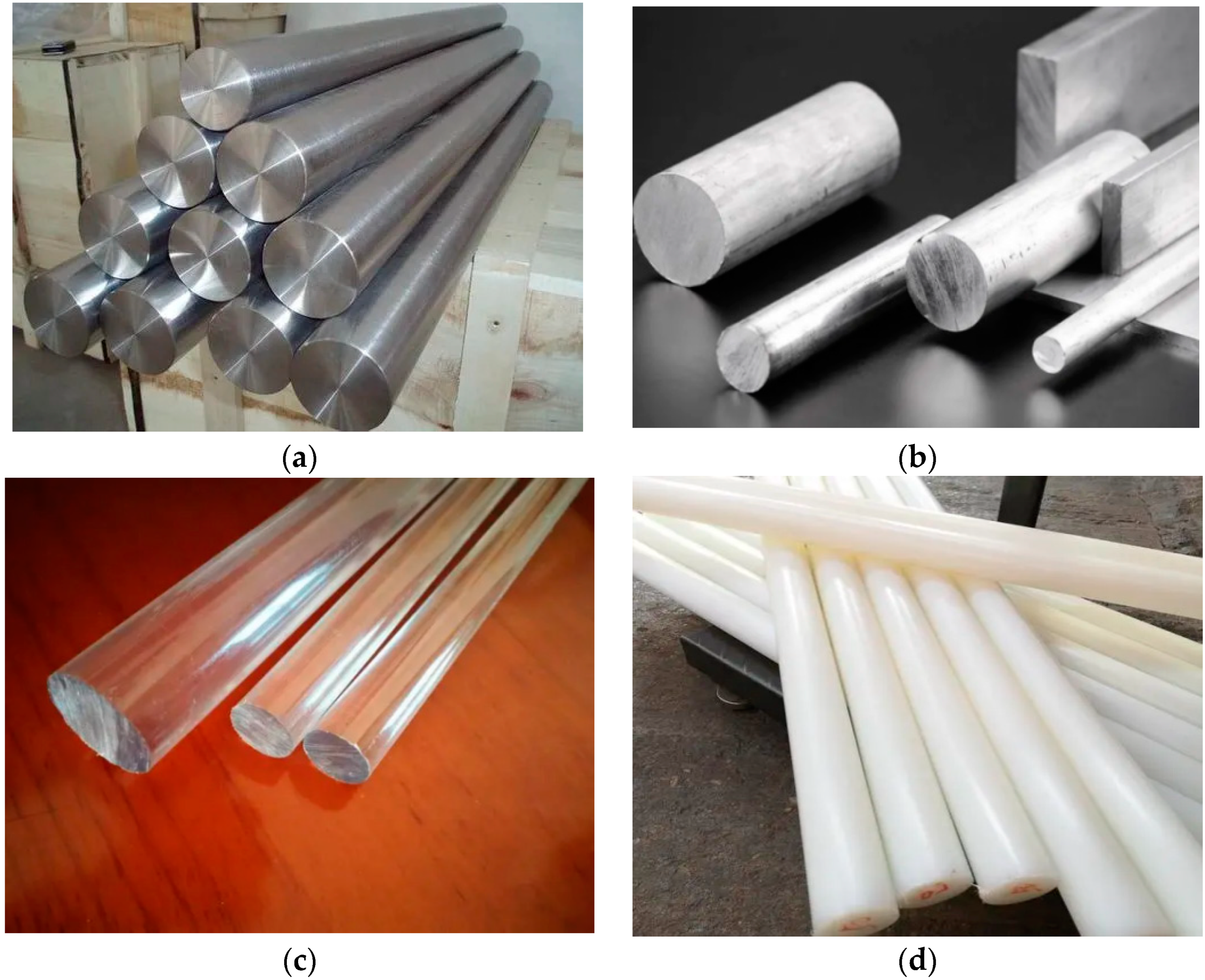
  • Impedance matching between the pressure bar and the specimen is of great significance for the SHPB testing of soft materials, polymeric materials, composite materials, and other low-impedance materials. By changing the pressure bar material, the wave impedance ratio of the pressure bar and the specimen material is changed, which fundamentally ensures the accuracy of the test results. A steel bar is recommended for test materials with a wave impedance greater than 1 × 10⁷ kg/(m2·s). If the wave impedance of the test materials is greater than 3.5 × 10⁶ kg/(m2·s) and is less than or equal to 1 × 10⁷ kg/(m2·s), an aluminum alloy bar is recommended. For materials whose wave impedance is less than 3.5 × 10⁶ kg/(m2·s), polymeric materials with lower wave impedance, such as polycarbonate, nylon, polymethyl methacrylate (PMMA), and polyethylene terephthalate (PET), are recommended as pressure bar materials. Modified gypsum composite materials can be used as a new material when a polymeric pressure bar cannot meet the test requirements. Impedance matching, combined with semiconductor strain gauge and quartz piezoelectric crystal technology, better solves the problem of a weak transmitted pulse signal in an SHPB test with low-impedance materials.
  • By introducing the Lagrangian analysis method into SHPB test data analysis, it has been realized that a reliable material dynamic constitutive relationship can be obtained through conservation analysis and calculation when a test material cannot meet the two basic assumptions. In combination with the law of energy conservation (conservation of momentum and conservation of mass), the Lagrangian analysis method can be applied to dynamic load impact tests on porous media materials without being based on the two basic assumptions of the SHPB test. The combined application of the Lagrangian analysis method and the SHPB test technique provides a new approach to analyzing the dynamic mechanical properties of materials, which can be an effective supplement to the traditional SHPB test.
  • The main technical gap of the SHPB at this stage is the inapplicability to porous materials (such as honeycomb aluminum, foam concrete, etc.). When a stress wave propagates in the internal structure, two-dimensional or three-dimensional reflection and refraction occur, which results in the experiment not meeting the one-dimensional stress wave assumption. Therefore, the processed experimental data also has a large deviation from the theoretical value. The solution for this problem is to use conservation of energy to analyze experimental data and introduce the Lagrangian analysis method into SHPB.
  • The improvement and innovation in the SHPB can be divided into two aspects: an air-pressure-driving system and pressure bar material. Currently, most of the SHPB devices use a pneumatic driving system to launch the impact bar, which makes the setting air pressure value and the actual impact pressure have a non-negligible deviation. The impact bar speed is different when the same impact air pressure is set. The test errors caused by the factor of shock pressure are too large to be eliminated through simple measures. The impact speed can be accurately and effectively controlled by changing the driving mode of the impact bar, such as by using an electromagnetic driving technique instead of the traditional pneumatic driving mode. On the other hand, in order to satisfy the requirements of the test and ensure the accuracy of the experimental results, it is necessary to ensure that there is excellent impedance matching between the sample and pressure bar as much as possible. In view of the diversity of test materials, it is essential to develop new pressure bar materials, such as modified gypsum composites.

Author Contributions

Conceptualization, Y.Y. and Q.L.; methodology, Y.Y. and Q.L.; validation, L.Q.; investigation, Y.Y.; resources, Y.Y.; writing—original draft preparation, Y.Y.; writing—review and editing, Q.L.; supervision, L.Q.; funding acquisition, Q.L. All authors have read and agreed to the published version of the manuscript.

Funding

This research was funded by the National Natural Science Foundation of China under grant number 52274107, the Interdisciplinary Research Project for Young Teachers of USTB under grant number FRF-IDRY-GD21-001 and the Excellent Youth Team Project for the Central Universities under grant number FRF-EYIT-23-01.

Data Availability Statement

The data presented in this study are available on request from the corresponding author.

Conflicts of Interest

The authors declare no conflict of interest.

References

  1. Zhu, B.; Jiang, N.; Zhou, C.B.; Luo, X.D.; Li, H.B.; Chang, X.; Xia, Y.Q. Dynamic interaction of the pipe-soil subject to underground blasting excavation vibration in an urban soil-rock stratum. Tunn. Undergr. Space Technol. 2022, 129, 104700. [Google Scholar] [CrossRef]
  2. Chen, Y.; Ding, J.L.; Babaiasl, M.; Yang, F.; Swensen, J.P. Characterization and modeling of a thermoplastic elastomer tissue simulant under uniaxial compression loading for a wide range of strain rates. J. Mech. Behav. Biomed. Mater. 2022, 131, 105218. [Google Scholar] [CrossRef]
  3. Liao, Z.Y.; Zhu, J.B.; Xia, K.W.; Tang, C.A. Determination of dynamic compressive and tensile behavior of rocks from numerical tests of split Hopkinson pressure and tension bars. Rock Mech. Rock Eng. 2016, 49, 3917–3934. [Google Scholar] [CrossRef]
  4. Kumar, S.; Malik, N.; Cinelli, P.; Sharma, V. High Strain Rate Behavior of Stir Cast Hybrid Al-Si Matrix Composites Using Split Hopkinson Pressure Bar. Silicon 2023, 1–10. [Google Scholar] [CrossRef]
  5. Yang, S.Q.; Li, Y.; Ma, G.W.; Sun, B.W.; Yang, J.; Xu, J.; Dai, Y.H. Experiment and numerical simulation study of dynamic mechanical behavior of granite specimen after high temperature treatment. Comput. Geotech. 2023, 154, 105111. [Google Scholar] [CrossRef]
  6. Chen, J.; Xiang, D.; Wang, Z.; Wu, G.; Wang, G. Dynamic tensile strength enhancement of concrete in split Hopkinson pressure bar test. Adv. Mech. Eng. 2018, 10, 1687814018782301. [Google Scholar] [CrossRef]
  7. Kumar, D.; Ruan, D.; Khaderi, S.N. Triaxial Characterization of Foams at High Strain Rate Using Split-Hopkinson Pressure Bar. Exp. Mech. 2023, 63, 1171–1192. [Google Scholar] [CrossRef]
  8. Zhao, G.; Li, X.; Xu, Y.; Xia, K. A modified triaxial split Hopkinson pressure bar (SHPB) system for quantifying the dynamic compressive response of porous rocks subjected to coupled hydraulic-mechanical loading. Geomech. Geophys. Geo-Energy Geo-Resour. 2022, 8, 29. [Google Scholar] [CrossRef]
  9. Zhu, C.X.; Sun, J.X.; Gong, J.; Wang, F.E. Experimental and numerical research of crack propagation process and energy dissipation law of grouting specimens under radial impact load. Front. Earth Sci. 2023, 10, 1037756. [Google Scholar] [CrossRef]
  10. Liu, F.; Li, Q.M. Strain-rate effect of polymers and correction methodology in a SHPB test. Int. J. Impact Eng. 2022, 161, 104109. [Google Scholar] [CrossRef]
  11. Yue, C.J.; Chen, L.; Yuan, J.Y.; Li, Q.Y.; Xu, L.F. A new analytical method for impact splitting strain rate in Brazilian disc test based on SHPB. Mater. Struct. 2023, 56, 66. [Google Scholar] [CrossRef]
  12. Tang, W.; Zhai, C.; Yu, X.; Xu, J.H.; Sun, Y.; Cong, Y.Z.; Zheng, Y.F.; Wang, Y. Dynamic Brazilian splitting experiment of bedding shale based on continuum-discrete coupled method. Int. J. Impact Eng. 2022, 168, 104289. [Google Scholar] [CrossRef]
  13. Zhu, W.C.; Niu, L.L.; Li, S.H.; Xu, Z.H. Dynamic Brazilian Test of Rock Under Intermediate Strain Rate: Pendulum Hammer-Driven SHPB Test and Numerical Simulation. Rock Mech. Rock Eng. 2015, 48, 1867–1881. [Google Scholar] [CrossRef]
  14. Imani, M.; Nejati, H.R.; Goshtasbi, K. Dynamic response and failure mechanism of Brazilian disk specimens at high strain rate. Soil Dyn. Earthq. Eng. 2017, 100, 261–269. [Google Scholar] [CrossRef]
  15. Zhang, Y.H.; Wang, Q.; Han, D.F.; Xue, Y.Z.; Lu, S.C.; Wang, P.G. Dynamic splitting tensile behaviours of distilled-water and river-water ice using a modified SHPB setup. Int. J. Impact Eng. 2020, 145, 103686. [Google Scholar] [CrossRef]
  16. Liu, C.J.; Deng, H.W.; Zhao, H.T.; Zhang, J. Effects of freeze-thaw treatment on the dynamic tensile strength of granite using the Brazilian test. Cold Reg. Sci. Technol. 2018, 155, 327–332. [Google Scholar] [CrossRef]
  17. Ai, D.H.; Zhao, Y.C.; Wang, Q.F.; Li, C.W. Experimental and numerical investigation of crack propagation and dynamic properties of rock in SHPB indirect tension test. Int. J. Impact Eng. 2019, 126, 135–146. [Google Scholar] [CrossRef]
  18. Feng, W.H.; Liu, F.; Yang, F.; Li, L.J.; Jing, L. Experimental study on dynamic split tensile properties of rubber concrete. Constr. Build. Mater. 2018, 165, 675–687. [Google Scholar] [CrossRef]
  19. Hopkinson, B.X. A method of measuring the pressure produced in the detonation of high, explosives or by the impact of bullets. Philosophical Transactions of the Royal Society of London. Ser. A Contain. Pap. A Math. Phys. Character 1914, 213, 437–456. [Google Scholar] [CrossRef]
  20. Davies, R.M. A critical study of the Hopkinson pressure bar. Philosophical Transactions of the Royal Society of London. Ser. A Math. Phys. Sci. 1948, 240, 375–457. [Google Scholar] [CrossRef]
  21. Kolsky, H. An investigation of the mechanical properties of materials at very high rates of loading. Proc. Phys. Soc. Sect. B 1949, 62, 676. [Google Scholar] [CrossRef]
  22. Xia, K.W.; Wang, S.; Xu, Y. Advanced in experimental studies for deep rock dynamics. Chin. J. Rock Mech. Eng. 2021, 40, 448–475. (In Chinese) [Google Scholar] [CrossRef]
  23. Harding, J.; Wood, E.O.; Campbell, J.D. Tensile testing of materials at impact rates of strain. J. Mech. Eng. Sci. 1960, 2, 88–96. [Google Scholar] [CrossRef]
  24. Lindholm, U.S. Some experiments with the split hopkinson pressure bar. J. Mech. Phys. Solids 1964, 12, 317–335. [Google Scholar] [CrossRef]
  25. Baker, W.E.; Yew, C.H. Strain-Rate Effects in the Propagation of Torsional Plastic Waves. J. Appl. Mech. 1966, 33, 917–923. [Google Scholar] [CrossRef]
  26. Cai, M.; Kaiser, P.K.; Suorineni, F.; Su, K. A study on the dynamic behavior of the Meuse/Haute-Marne argillite. Phys. Chem. Earth 2007, 32, 907–916. [Google Scholar] [CrossRef]
  27. Li, Y.; Xia, C. Time-dependent tests on intact rocks in uniaxial compression. Int. J. Rock Mech. Min. Sci. 2000, 37, 467–475. [Google Scholar] [CrossRef]
  28. Li, H.B.; Zhao, J.; Li, J.R.; Liu, Y.Q.; Zhou, Q.C. Experimental studies on the strength of different rock types under dynamic compression. Int. J. Rock Mech. Min. Sci. 2004, 41, 68–73. [Google Scholar] [CrossRef]
  29. Li, X.B.; Lok, T.S.; Zhao, J. Dynamic characteristics of granite subjected to intermediate loading rate. Rock Mech. Rock Eng. 2005, 38, 21–39. [Google Scholar] [CrossRef]
  30. Sylven, E.T.; Agarwal, S.; Briant, C.L.; Cleveland, R.O. High strain rate testing of kidney stones. J. Mater. Sci. Mater. Med. 2004, 15, 613–617. [Google Scholar] [CrossRef] [PubMed]
  31. Xia, K.; Nasseri, M.H.B.; Mohanty, B.; Lu, F.; Chen, R.; Luo, S.N. Effects of microstructures on dynamic compression of Barre granite. Int. J. Rock Mech. Min. Sci. 2008, 45, 879–887. [Google Scholar] [CrossRef]
  32. Gong, J.C.; Malvern, L.E.; Jenkins, D.A. Dispersion Investigation in the Split Hopkinson Pressure Bar. J. Eng. Mater. Technol. 1990, 112, 309–314. [Google Scholar] [CrossRef]
  33. Ellwood, S.; Griffiths, L.J.; Parry, D.J. Materials testing at high constant strain rates. J. Phys. E Sci. Instrum. 1982, 15, 280. [Google Scholar] [CrossRef]
  34. Parry, D.J.; Walker, A.G.; Dixon, P.R. Hopkinson bar pulse smoothing. Meas. Sci. Technol. 1995, 6, 443. [Google Scholar] [CrossRef]
  35. Tao, J.L.; Tian, C.J.; Chen, Y.Z.; Chen, G.; Zhang, F.J.; Li, S.Z.; Huang, X.C. Investigation of experimental method to obtain constant strain rate of specimen in SHPB. Explos. Shock Waves 2004, 5, 413–418. (In Chinese) [Google Scholar]
  36. Frew, D.J.; Forrestal, M.J.; Chen, W. Pulse shaping techniques for testing elastic-plastic materials with a split Hopkinson pressure bar. Exp. Mech. 2005, 45, 186–196. [Google Scholar] [CrossRef]
  37. Guo, Y.; Gao, G.; Jing, L.; Shim, V. Response of high-strength concrete to dynamic compressive loading. Int. J. Impact Eng. 2017, 108, 114–135. [Google Scholar] [CrossRef]
  38. Abotula, S.; Chalivendra, V.B. An experimental and numerical investigation of the static and dynamic constitutive behaviour of aluminium alloys. J. Strain Anal. Eng. Des. 2010, 45, 555–565. [Google Scholar] [CrossRef]
  39. Rabbi, M.; Chalivendra, V.; Li, D. A novel approach to increase dynamic fracture toughness of additively manufactured polymer. Exp. Mech. 2019, 59, 899–911. [Google Scholar] [CrossRef]
  40. Zhang, F.; Zhu, Z.; Ma, W.; Zhou, Z.; Fu, T. A unified viscoplastic model and strain rate–temperature equivalence of frozen soil under impact loading. J. Mech. Phys. Solids 2021, 152, 104413. [Google Scholar] [CrossRef]
  41. Heard, W.F.; Martin, B.E.; Nie, X.; Slawson, T.; Basu, P.K. Annular pulse shaping technique for large-diameter Kolsky bar experiments on concrete. Exp. Mech. 2014, 54, 1343–1354. [Google Scholar] [CrossRef]
  42. Huang, B.; Xiao, Y. Compressive impact tests of lightweight concrete with 155-mm-diameter spilt hopkinson pressure bar. Cem. Concr. Compos. 2020, 114, 103816. [Google Scholar] [CrossRef]
  43. Liu, S.; Xu, J. Experimental and Numerical Analysis of Qinling Mountain Engineered Rocks during Pulse-Shaped SHPB Test. Int. J. Nonlinear Sci. Numer. Simul. 2015, 16, 165–171. [Google Scholar] [CrossRef]
  44. Naghdabadi, R.; Ashrafi, M.; Arghavani, J. Experimental and numerical investigation of pulse-shaped split Hopkinson pressure bar test. Mater. Sci. Eng. A 2012, 539, 285–293. [Google Scholar] [CrossRef]
  45. Hassan, M.; Wille, K. Experimental impact analysis on ultra-high performance concrete (UHPC) for achieving stress equilibrium (SE) and constant strain rate (CSR) in Split Hopkinson pressure bar (SHPB) using pulse shaping technique. Constr. Build. Mater. 2017, 144, 747–757. [Google Scholar] [CrossRef]
  46. Chaudhry, M.S.; Carrick, R.; Czekanski, A. Finite element modelling of a modified Kolsky bar developed for high strain rate testing of Elastomers. In Proceedings of the ASME International Mechanical Engineering Congress and Exposition, Houston, TX, USA, 13–19 November 2015; Volume 57526, p. V009T12A050. [Google Scholar] [CrossRef]
  47. Lee, O.S.; Choi, H.; Kim, H. High-temperature dynamic deformation of aluminum alloys using SHPB. J. Mech. Sci. Technol. 2011, 25, 143–148. [Google Scholar] [CrossRef]
  48. Williams, B.; Sun, Q.; Heard, W.; Loeffler, C.; Graham, S.; Vankirk, G.; Nie, X. Investigation of strain-rate and pressure effects for high-strength concrete using a novel large-diameter triaxial Kolsky bar technique. Cem. Concr. Compos. 2021, 121, 104085. [Google Scholar] [CrossRef]
  49. Yavuz, H.; Tufekci, K.; Kayacan, R.; Cevizci, H. Predicting the dynamic compressive strength of carbonate rocks from quasi-static properties. Exp. Mech. 2013, 53, 367–376. [Google Scholar] [CrossRef]
  50. Chen, X.; Wu, S.; Zhou, J. Quantification of dynamic tensile behavior of cement-based materials. Constr. Build. Mater. 2014, 51, 15–23. [Google Scholar] [CrossRef]
  51. Nemat-Nasser, S.; Choi, J.-Y.; Guo, W.-G.; Isaacs, J.B. Very high strain-rate response of a NiTi shape-memory alloy. Mech. Mater. 2005, 37, 287–298. [Google Scholar] [CrossRef]
  52. Wang, B.Z. Research on Dynamic Mechanical Properties of Soft Muscle Tissue; University of Science and Technology of China: Hefei, China, 2010; pp. 85–89. (In Chinese) [Google Scholar]
  53. Oh, S.-W.; Min, G.-J.; Park, S.-W.; Kim, M.-S.; Obara, Y.; Cho, S.-H. Anisotropic influence of fracture toughness on loading rate dependency for granitic rocks. Eng. Fract. Mech. 2019, 221, 106677. [Google Scholar] [CrossRef]
  54. On, T.; LaVigne, P.A.; Lambros, J. Development of plastic nonlinear waves in one-dimensional ductile granular chains under impact loading. Mech. Mater. 2014, 68, 29–37. [Google Scholar] [CrossRef]
  55. Wang, Y.; Wang, Z.; Liang, X.; An, M. Experimental and numerical studies on dynamic compressive behavior of reactive powder concretes. Acta Mech. Solida Sin. 2008, 21, 420–430. [Google Scholar] [CrossRef]
  56. Sun, C.X.; Ju, Y.T.; Zheng, J.; Zheng, Y.; Zhang, J.F. Experimental research on the compressive properties of modified double base propellant at low and high strain rates. Acta Armamentarii 2013, 34, 698–703. (In Chinese) [Google Scholar]
  57. Vecchio, K.S.; Jiang, F. Improved pulse shaping to achieve constant strain rate and stress equilibrium in split-Hopkinson pressure bar testing. Metall. Mater. Trans. A 2007, 38, 2655–2665. [Google Scholar] [CrossRef]
  58. Panowicz, R.; Trypolin, M. Shaping the incident impulse in the modified split Hopkinson pressure bar method. AIP Conf. Proc. 2019, 2078, 20072. [Google Scholar] [CrossRef]
  59. Das, N.; Nanthagopalan, P. State-of-the-art review on ultra high performance concrete-Ballistic and blast perspective. Cem. Concr. Compos. 2022, 127, 104383. [Google Scholar] [CrossRef]
  60. Pang, S.; Tao, W.; Liang, Y.; Liu, Y.; Huan, S. A modified method of pulse-shaper technique applied in SHPB. Compos. Part B Eng. 2019, 165, 215–221. [Google Scholar] [CrossRef]
  61. Chen, X.; Ge, L.; Zhou, J.; Wu, S. Experimental study on split Hopkinson pressure bar pulse-shaping techniques for concrete. J. Mater. Civ. Eng. 2016, 28, 4015196. [Google Scholar] [CrossRef]
  62. Cloete, T.J.; van der Westhuizen, A.; Kok, S.; Nurick, G.N. A tapered striker pulse shaping technique for uniform strain rate dynamic compression of bovine bone. EDP Sci. 2009, 1, 901–907. [Google Scholar] [CrossRef]
  63. Ma, Q.Y.; Su, Q.Q.; Ma, D.D.; Yuan, P. SHPB experimental study on dynamic characteristics and failure behaviors of sandstone containing weakly filled joint with various angles in deep roadways. Chin. J. Rock Mech. Eng. 2020, 39, 1104–1116. (In Chinese) [Google Scholar] [CrossRef]
  64. Gong, F.; Lu, D.; Liu, X.; Man, K. Dynamic characteristics of sandstone at high strain rates and different confining pressures. Disaster Adv. 2013, 6, 466–472. [Google Scholar]
  65. Zhang, Y.; Deng, H.; Deng, J.; Liu, C.; Ke, B. Peridynamics simulation of crack propagation of ring-shaped specimen like rock under dynamic loading. Int. J. Rock Mech. Min. Sci. 2019, 123, 104093. [Google Scholar] [CrossRef]
  66. Yokoyama, T.; Nakai, K.; Yatim, N.H.M. High strain-rate compressive properties and constitutive modeling of bulk structural adhesives. J. Adhes. 2012, 88, 471–486. [Google Scholar] [CrossRef]
  67. Liu, X.H.; Xue, Y.; Zheng, Y.; Gui, X. Research on energy release in coal rock fragmentation process under impact load. Chin. J. Rock Mech. Eng. 2021, 40, 3201–3211. (In Chinese) [Google Scholar] [CrossRef]
  68. Guo, R.Q.; Ren, H.Q.; Zhang, L.; Long, Z.L.; Wu, X.Y.; Xu, X.Y.; Li, Z.B.; Huang, K. Research progress of large-diameter split Hopkinson bar experimental technique. Acta Armamentarii 2019, 40, 1518–1536. (In Chinese) [Google Scholar] [CrossRef]
  69. Wang, L.L. Foundation of Stress Waves, 2nd ed.; National Defense Industry Press: Beijing, China, 2005; pp. 52–60. (In Chinese) [Google Scholar]
  70. Yang, L.; Shim, V. An analysis of stress uniformity in split Hopkinson bar test specimens. Int. J. Impact Eng. 2005, 31, 129–150. [Google Scholar] [CrossRef]
  71. Lu, F.; Lin, Y.; Wang, X.; Lu, L.; Chen, R. A theoretical analysis about the influence of interfacial friction in SHPB tests. Int. J. Impact Eng. 2015, 79, 95–101. [Google Scholar] [CrossRef]
  72. Rabbi, F.; Chalivendra, V.; Kim, Y. Dynamic constitutive response of novel auxetic Kevlar®/epoxy composites. Compos. Struct. 2018, 195, 1–13. [Google Scholar] [CrossRef]
  73. Chen, R. Experimental Studies on Mechanical Properties of a PBX under Various Dynamic Loading Conditions; Graduate School of National University of Defense Technology: Changsha, China, 2010; pp. 47–50. (In Chinese) [Google Scholar]
  74. Shemirani, A.B.; Naghdabadi, R.; Ashrafi, M. Experimental and numerical study on choosing proper pulse shapers for testing concrete specimens by split Hopkinson pressure bar apparatus. Constr. Build. Mater. 2016, 125, 326–336. [Google Scholar] [CrossRef]
  75. Song, B.; Chen, W. Loading and unloading split Hopkinson pressure bar pulse-shaping techniques for dynamic hysteretic loops. Exp. Mech. 2004, 44, 622–627. [Google Scholar] [CrossRef]
  76. Bragov, A.M.; Igumnov, L.A.; Konstantinov, A.Y.; Kruszka, L.; Lamzin, D.A.; Lomunov, A.K. Methodological aspects of testing brittle materials using the split Hopkinson bar technique. Strain 2021, 57, e12389. [Google Scholar] [CrossRef]
  77. Ding, Y.Q. Experimental Characterization and Constitutive Modeling pf Partially Saturated Clay under Dynamic Loading Conditions; Graduate School of National University of Defense Technology: Changsha, China, 2013; pp. 45–48. (In Chinese) [Google Scholar]
  78. Xu, M.; Wille, K. Numerical investigation of the effects of pulse shaper, lateral inertia, and friction on the calculated strain-rate sensitivity of UHP-FRC using a split Hopkinson pressure bar. J. Mater. Civ. Eng. 2016, 28, 4016114. [Google Scholar] [CrossRef]
  79. Rotbaum, Y.; Puiu, C.; Rittel, D.; Domingos, M. Quasi-static and dynamic in vitro mechanical response of 3D printed scaffolds with tailored pore size and architectures. Mater. Sci. Eng. C 2019, 96, 176–182. [Google Scholar] [CrossRef]
  80. Chen, R.; Cheng, L.; Lin, Y.; Lu, F. Studies on the dynamic fracture properties and failure modes of a PBX. Int. J. Appl. Mech. 2014, 6, 1450039. [Google Scholar] [CrossRef]
  81. Tian, B. Research on Dynamic Mechanical Properties of Modified Double-Base Propellant under High Strain Rate; Beijing Institute of Technology: Beijing, China, 2015; pp. 24–29. (In Chinese) [Google Scholar]
  82. Luo, H.; Lu, H.; Leventis, N. The compressive behavior of isocyanate-crosslinked silica aerogel at high strain rates. Mech. Time-Depend. Mater. 2006, 10, 83–111. [Google Scholar] [CrossRef]
  83. Trexler, M.; Lennon, A.; Wickwire, A.; Harrigan, T.; Luong, Q.; Graham, J.; Maisano, A.; Roberts, J.; Merkle, A. Verification and implementation of a modified split Hopkinson pressure bar technique for characterizing biological tissue and soft biosimulant materials under dynamic shear loading. J. Mech. Behav. Biomed. Mater. 2011, 4, 1920–1928. [Google Scholar] [CrossRef]
  84. Song, B.; Chen, W. Dynamic stress equilibration in split Hopkinson pressure bar tests on soft materials. Exp. Mech. 2004, 44, 300–312. [Google Scholar] [CrossRef]
  85. Lu, T.H. Studies on the Shock Compression Behaviors of Concrete and Steel Reinforced Concrete Based on the Split Hopkinson Pressure Bar; University of Science and Technology of China: He Fei, China, 2018; pp. 24–26. (In Chinese) [Google Scholar]
  86. Sharma, A.; Shukla, A.; Prosser, R.A. Mechanical characterization of soft materials using high speed photography and split Hopkinson pressure bar technique. J. Mater. Sci. 2002, 37, 1005–1017. [Google Scholar] [CrossRef]
  87. Chen, J.; Patnaik, S.S.; Prabhu, R.K.; Priddy, L.B.; Bouvard, J.-L.; Marin, E.; Horstemeyer, M.F.; Liao, J.; Williams, L.N. Mechanical response of porcine liver tissue under high strain rate compression. Bioengineering 2019, 6, 49. [Google Scholar] [CrossRef]
  88. Xu, P.; Tang, L.; Zhang, Y.; Ni, P.; Liu, Z.; Jiang, Z.; Liu, Y.; Zhou, L. SHPB experimental method for ultra-soft materials in solution environment. Int. J. Impact Eng. 2022, 159, 104051. [Google Scholar] [CrossRef]
  89. Liu, J.; Chen, Z.; Xu, F.; Chen, G. Experimental study of dynamic properties of compacted clay under different compaction degrees and water content. Rock Soil Mech. 2012, 33, 1631–1639. (In Chinese) [Google Scholar] [CrossRef]
  90. Casem, D.T.; Dwivedi, A.K.; Mrozek, R.A.; Lenhart, J.L. Compression response of a thermoplastic elastomer gel tissue surrogate over a range of strain-rates. Int. J. Solids Struct. 2014, 51, 2037–2046. [Google Scholar] [CrossRef]
  91. Lee, O.S.; Lee, J.W.; Kim, S.H. Dynamic deformation behavior of rubber (NR/NBR) under high strain rate compressive loading. Key Eng. Mater. 2005, 297, 172–177. [Google Scholar] [CrossRef]
  92. Martarelli, M.; Mancini, E.; Lonzi, B.; Sasso, M. Sensor calibration of polymeric Hopkinson bars for dynamic testing of soft materials. Meas. Sci. Technol. 2018, 29, 25601. [Google Scholar] [CrossRef]
  93. Xie, B.X. Research on the Dynamic Testing Techniques and Properties of Lightweight and Soft Materials; South China University of Technology: Guangzhou, China, 2017; pp. 73–79. (In Chinese) [Google Scholar]
  94. Sasso, M.; Antonelli, M.G.; Mancini, E.; Radoni, M.; Amodio, D. Experimental and numerical characterization of a polymeric Hopkinson bar by DTMA. Int. J. Impact Eng. 2017, 103, 50–63. [Google Scholar] [CrossRef]
  95. Salisbury, C.P.; Cronin, D.S. Mechanical properties of ballistic gelatin at high deformation rates. Exp. Mech. 2009, 49, 829–840. [Google Scholar] [CrossRef]
  96. Van Sligtenhorst, C.; Cronin, D.S.; Brodland, G.W. High strain rate compressive properties of bovine muscle tissue determined using a split Hopkinson bar apparatus. J. Biomech. 2006, 39, 1852–1858. [Google Scholar] [CrossRef]
  97. Xie, B.X.; Tang, L.Q.; Jiang, X.Q.; Shi, J.L.; Zhao, W.J.; She, H.S.; Zhang, Y.R.; Liu, Y.P.; Jiang, Z.Y. A double-striker electromagnetic driving SHPB system for soft materials. Explos. Shock Waves 2019, 39, 69–75. (In Chinese) [Google Scholar]
  98. Jiang, T.; Xue, P.; Butt, H. Pulse shaper design for dynamic testing of viscoelastic materials using polymeric SHPB. Int. J. Impact Eng. 2015, 79, 45–52. [Google Scholar] [CrossRef]
  99. Baranowski, P.; Malachowski, J.; Janiszewski, J.; Wekezer, J. Detailed tyre FE modelling with multistage validation for dynamic analysis. Mater. Des. 2016, 96, 68–79. [Google Scholar] [CrossRef]
  100. Doman, D.A.; Cronin, D.S.; Salisbury, C.P. Characterization of polyurethane rubber at high deformation rates. Exp. Mech. 2006, 46, 367–376. [Google Scholar] [CrossRef]
  101. Chen, J.F. Study on Characterization of Hydrogel by Viscoelastic Indentation and Its Impact Characteristics in Solution; South China University of Technology: Guangzhou, China, 2018; pp. 37–44. (In Chinese) [Google Scholar]
  102. Bracq, A.; Haugou, G.; Delille, R.; Lauro, F.; Roth, S.; Mauzac, O. Experimental study of the strain rate dependence of a synthetic gel for ballistic blunt trauma assessment. J. Mech. Behav. Biomed. Mater. 2017, 72, 138–147. [Google Scholar] [CrossRef] [PubMed]
  103. Weeks, J.S.; Ravichandran, G. High strain-rate compression behavior of polymeric rod and plate Kelvin lattice structures. Mech. Mater. 2022, 166, 104216. [Google Scholar] [CrossRef]
  104. Ma, X.; Li, X.; Zheng, X.; Li, K.; Hu, Q.; Li, J. Crack initiation and potential hot-spot formation around a cylindrical defect under dynamic compression. J. Appl. Phys. 2017, 122, 185104. [Google Scholar] [CrossRef]
  105. Porcaro, R.; Langseth, M.; Hanssen, A.; Zhao, H.; Weyer, S.; Hooputra, H. Crashworthiness of self-piercing riveted connections. Int. J. Impact Eng. 2008, 35, 1251–1266. [Google Scholar] [CrossRef]
  106. Pochhammer, L. On the propagation velocities of small oscillations in an unlimited isotropic circular cylinder. J. Reine Angew. Math. 1876, 81, 324–336. [Google Scholar]
  107. Chree, C. The equations of an isotropic elastic solid in polar and cylindrical co-ordinates their solution and application. Trans. Camb. Philos. Soc. 1889, 14, 250–369. [Google Scholar]
  108. Follansbee, P.S.; Frantz, C. Wave propagation in the split Hopkinson pressure bar. J. Eng. Mater. Technol. 1983, 105, 61–66. [Google Scholar] [CrossRef]
  109. Bacon, C. An experimental method for considering dispersion and attenuation in a viscoelastic Hopkinson bar. Exp. Mech. 1998, 38, 242–249. [Google Scholar] [CrossRef]
  110. Bustamante, M.C.; Cronin, D.S. Assessment of Fluid Cavitation Threshold Using a Polymeric Split Hopkinson Bar-Confinement Chamber Apparatus. In Mechanics of Biological Systems & Micro-and Nanomechanics; Proceedings of the 2018 Annual Conference on Experimental and Applied Mechanics; Springer International Publishing: Berlin/Heidelberg, Germany, 2019; Volume 4, pp. 95–99. [Google Scholar] [CrossRef]
  111. Bustamante, M.; Cronin, D. Cavitation threshold evaluation of porcine cerebrospinal fluid using a Polymeric Split Hopkinson Pressure Bar-Confinement chamber apparatus. J. Mech. Behav. Biomed. Mater. 2019, 100, 103400. [Google Scholar] [CrossRef]
  112. Bustamante, M.C.; Singh, D.; Cronin, D.S. Polymeric Hopkinson bar-confinement chamber apparatus to evaluate fluid cavitation. Exp. Mech. 2018, 58, 55–74. [Google Scholar] [CrossRef]
  113. Nie, H.; Suo, T.; Wu, B.; Li, Y.; Zhao, H. A versatile split Hopkinson pressure bar using electromagnetic loading. Int. J. Impact Eng. 2018, 116, 94–104. [Google Scholar] [CrossRef]
  114. Werner, B.; Daniel, I. Characterization and modeling of polymeric matrix under multi-axial static and dynamic loading. Compos. Sci. Technol. 2014, 102, 113–119. [Google Scholar] [CrossRef]
  115. Gonçalves, R.; Martinho, A.; Oliveira, J. Evaluating the potential use of recycled glass fibers for the development of gypsum-based composites. Constr. Build. Mater. 2022, 321, 126320. [Google Scholar] [CrossRef]
  116. Sakthieswaran, N.; Sophia, M. Effect of superplasticizers on the properties of latex modified gypsum plaster. Constr. Build. Mater. 2018, 179, 675–691. [Google Scholar] [CrossRef]
  117. Yu, Q.; Brouwers, H. Development of a self-compacting gypsum-based lightweight composite. Cem. Concr. Compos. 2012, 34, 1033–1043. [Google Scholar] [CrossRef]
  118. Zhu, Z.Y.; Wu, Q.S.; Tang, J.; Zhu, H.J.; Zhao, L.; Rui, Y.Y. Mechanical properties and microstructure of desulfurization gypsum modified by phenolic resin. J. Mater. Sci. Eng. 2016, 34, 119–122+126. (In Chinese) [Google Scholar] [CrossRef]
  119. Yang, L.; Jing, M.; Lu, L.; Zhu, X.; Zhao, P.; Chen, M.; Li, L.; Liu, J. Effects of modified materials prepared from wastes on the performance of flue gas desulfurization gypsum-based composite wall materials. Constr. Build. Mater. 2020, 257, 119519. [Google Scholar] [CrossRef]
  120. Magallanes-Rivera, R.; Juarez-Alvarado, C.; Valdez, P.; Mendoza-Rangel, J. Modified gypsum compounds: An ecological–economical choice to improve traditional plasters. Constr. Build. Mater. 2012, 37, 591–596. [Google Scholar] [CrossRef]
  121. Zając, K.; Czyżewski, A.; Kaszyńska, M.; Janus, M. Combined Effect of Photocatalyst, Superplasticizer, and Glass Fiber on the Photocatalytic Activity and Technical Parameters of Gypsum. Catalysts 2020, 10, 385. [Google Scholar] [CrossRef]
  122. Wu, Q.; Ma, H.; Chen, Q.; Huang, Z.; Zhang, C.; Yang, T. Preparation of waterproof block by silicate clinker modified FGD gypsum. Constr. Build. Mater. 2019, 214, 318–325. [Google Scholar] [CrossRef]
  123. Cao, L.J.; Jin, T.; Deng, S.Q.; Huang, J.; Chen, Y. Molding process and mechanism of “desulfurized gypsum-glass fiber” reinforced with melamine resin. J. Build. Mater. 2022, 25, 74–80. (In Chinese) [Google Scholar] [CrossRef]
  124. Khalil, A.; Tawfik, A.; Hegazy, A. Plaster composites modified morphology with enhanced compressive strength and water resistance characteristics. Constr. Build. Mater. 2018, 167, 55–64. [Google Scholar] [CrossRef]
  125. Iucolano, F.; Caputo, D.; Leboffe, F.; Liguori, B. Mechanical behavior of plaster reinforced with abaca fibers. Constr. Build. Mater. 2015, 99, 184–191. [Google Scholar] [CrossRef]
  126. Jian, S.; Yang, X.; Gao, W.; Li, B.; Gao, X.; Huang, W.; Tan, H.; Lei, Y. Study on performance and function mechanisms of whisker modified flue gas desulfurization (FGD) gypsum. Constr. Build. Mater. 2021, 301, 124341. [Google Scholar] [CrossRef]
  127. Qian, K.J. A Study on the Application of Quartz Crystal Sensor in Hopkinson Pressure Bar Test of Soft Materials; Zhejiang University: Hang Zhou, China, 2015; pp. 52–56. (In Chinese) [Google Scholar]
  128. Fowles, R.; Williams, R.F. Plane stress wave propagation in solids. J. Appl. Phys. 1970, 41, 360–363. [Google Scholar] [CrossRef]
  129. Fowles, R. Conservation relations for spherical and cylindrical stress waves. J. Appl. Phys. 1970, 41, 2740–2741. [Google Scholar] [CrossRef]
  130. Cowperthwaite, M.; Williams, R.F. Determination of constitutive relationships with multiple gauges in nondivergent waves. J. Appl. Phys. 1971, 42, 456–462. [Google Scholar] [CrossRef]
  131. Grady, D.E. Experimental analysis of spherical wave propagation. J. Geophys. Res. 1973, 78, 1299–1307. [Google Scholar] [CrossRef]
  132. Wang, L.L.; Zhu, J.; Lai, H.W. Understanding and interpreting of the measured wave signals in impact dynamics studies. Chin. J. High Press. Phys. 2010, 24, 279–285. (In Chinese) [Google Scholar]
  133. Wang, L.; Zhu, J.; Lai, H. A new method combining Lagrangian analysis with Hopkinson pressure bar technique. Strain 2011, 47, 173–182. [Google Scholar] [CrossRef]
  134. Wang, L.; Hu, S.; Yang, L.; Sun, Z.; Zhu, J.; Lai, H.; Ding, Y. Development of experimental methods for impact testing by combining Hopkinson pressure bar with other techniques. Acta Mech. Solida Sin. 2014, 27, 331–344. [Google Scholar] [CrossRef]
  135. Wang, L.; Ding, Y.; Yang, L. Experimental investigation on dynamic constitutive behavior of aluminum foams by new inverse methods from wave propagation measurements. Int. J. Impact Eng. 2013, 62, 48–59. [Google Scholar] [CrossRef]
  136. Zhu, J.; Cao, Y.-H.; Chen, J.-Y. Study on the evolution of dynamic mechanics properties of cement mortar under sulfate attack. Constr. Build. Mater. 2013, 43, 286–292. [Google Scholar] [CrossRef]
  137. Zhang, L.; Hu, S.S.; Liang, Z.X. Lagrange analysis of the stress-strain relation of concrete material under impact loading. Eng. Mech. 2005, 22, 163–166. (In Chinese) [Google Scholar]
  138. Ding, Y.; Wang, Y.; Zhang, Z.; Lai, H. Dynamic Testing Technique Based on Multi-channel Photonic Doppler Velocimetry for Investigating the Dynamic Behavior of Materials. Acta Mech. Solida Sin. 2019, 32, 725–736. [Google Scholar] [CrossRef]
  139. Yu, X.; Fu, Y.; Dong, X.; Zhou, F.; Ning, J. An Improved Lagrangian-Inverse Method for Evaluating the Dynamic Constitutive Parameters of Concrete. Materials 2020, 13, 1871. [Google Scholar] [CrossRef]
Figure 1. Schematic diagram of a split-Hopkinson pressure bar system.
Processes 11 03029 g001
Figure 2. Loading strain rate distribution diagram [26,27,28,29,30,31].
Processes 11 03029 g002
Figure 3. Comparison of effect before and after using a rubber shaper.
Processes 11 03029 g003
Figure 4. Different types of impact bars: (a) cylindrical impact bar; (b) spindle-shaped impact bar; (c) tapered impact bar.
Processes 11 03029 g004
Figure 5. Pressure bars of various materials: (a) steel bar; (b) aluminum bar; (c) polycarbonate bar; (d) nylon bar.
Processes 11 03029 g005
Figure 6. Test materials that do not meet the two basic assumptions: (a) copper foam; (b) porous Sic ceramics.
Processes 11 03029 g006
Table 1. Summary of the current applications of the incident pulse-shaping method.
Pulse-Shaping MaterialsTypes of MaterialsTypes of Test Specimens
Copper sheet (brass, red copper)brittle materialsconcrete, rock, inorganic glass, ceramic, cement mortar, frozen soil
composite materialsEpoxy resin composite, composite ceramic, cement-based composite
metallic materialsaluminum alloy, NiTi alloy, copper, cast iron
polymeric materialsacrylonitrile butadiene styrene (ABS)
soft materialssilicone rubber
Hardboardmetallic materialsbrass
soft materialsrubber, polyurethane plastic
composite materialsmodified double-base propellant
Rubberbrittle materialsrock, concrete
soft materialsnatural rubber (NR), nitrile butadiene rubber (NBR), silicone rubber, fatty soft tissue
Medical plastersoft materialsmuscle soft tissue
Medical tapebrittle materialsanimal skeletal tissue
Asbestos sheetcomposite materialsmodified double-base propellant
Vaselinesoft materialsgranular cementing materials
Table 2. Summary of main application status of special-shaped impact bar method.
Types of Impact BarIncident WaveformsTypes of MaterialsTypes of Test Specimens
Tapered impact barhalf-sine wave, sine wavebrittle materialsrock
Spindle-shaped impact barrock, concrete, high-strength mortar, ceramic
Table 3. Physical and mechanical parameters for various types of pressure bar materials.
Pressure Bar MaterialsDensity
ρ (kg/m3)
Wave Velocity C (m/s)Elastic Modulus E (GPa)Wave Impedance ρ C (kg/(m2·s))
Steel7800519021040,482,000
Aluminum alloy2770503670.2513,949,720
Polyethylene terephthalate168015434.02,592,240
Polymethyl methacrylate117817163.472,021,448
Nylon114017103.31,949,400
Polycarbonate118014202.3791,675,600
Room temperature is the condition for these parameters.
Table 4. Pressure bar material suggestion table corresponding to various test materials.
Types of MaterialsWave Impedance ρ C (kg/(m2·s))Types of Test SpecimensRecommended Pressure Bar Materials
Metallic materials1.4 × 107~4.0 × 10⁷iron, copper, titanium, and aluminum alloysteel
Brittle materials1.2 × 107~2.0 × 10⁷granite, sandstone, chert, etc.
5.0 × 10⁶~1.0 × 10⁷concrete, coal rock, infillaluminum alloy
Composite materials5.0 × 105~3.0 × 10⁷carbon fiber epoxy resin matrix composites, solid propellants, in situ composites, hollow sphere/alloy compositessteel, aluminum alloy, PET, PC
Polymeric materials4.0 × 105~6.0 × 10⁶PMMA, polymer-bonded explosives (PBXs), clear polyurethane films, phenolic laminatesaluminum alloy, PET, PC, nylon
Soft materials3.0 × 104~1.7 × 10⁵polyurethane, TPE gel, polyvinyl alcohol (PVA) hydrogel, nitrile butadiene rubber (NBR), silicone rubber, liquid silicone rubber (LSR), muscle soft tissue, animal liver tissuePET, PMMA, PC, nylon
Disclaimer/Publisher’s Note: The statements, opinions and data contained in all publications are solely those of the individual author(s) and contributor(s) and not of MDPI and/or the editor(s). MDPI and/or the editor(s) disclaim responsibility for any injury to people or property resulting from any ideas, methods, instructions or products referred to in the content.

