Article

Analysis of Flow Characteristics at the Inlet of a Circular Involute Variable Wall Thickness Scroll Expander

College of Mechanical and Electronic Engineering, Shandong University of Science and Technology, Qingdao 266590, China
*
Author to whom correspondence should be addressed.
Processes 2023, 11(11), 3117; https://doi.org/10.3390/pr11113117
Submission received: 26 September 2023 / Revised: 24 October 2023 / Accepted: 27 October 2023 / Published: 31 October 2023

Abstract

:
This paper mainly studies the effects of the inlet shape on the internal flow field and the output characteristics of a scroll expander. Based on circular involute variable wall thickness scroll profiles, three inlet working cavities are numerically simulated using the CFD method and dynamic mesh technique, thus obtaining the internal flow field, the inlet flow rate, the transient gas force, and the change rule of inlet power loss in the working cavity. The results show that the pressure distribution in the working cavity of the scroll expanders with elliptical and double circular groove inlets is more uniform than that in expanders with circular inlets. The high-pressure gas impacting the wall of the scroll teeth at different speeds results in a serious loss of mechanical energy of the gas and a large amount of swirling phenomena in the working cavity. Compared to the circular inlet, the output torque and inlet flow rate of scroll expanders with double circular grooves and elliptical inlets are increased, and the inlet power loss is decreased by more than 40%. Therefore, the double arc groove and elliptical air inlet provide superior performance compared to conventional circular air inlet scroll expanders.

1. Introduction

In an organic rankine cycle (ORC) power generation system, the expander serves as the core component of the system [1,2,3]; in it, the scroll expander has the advantages of a simple structure, large built-in volume ratio, and high isentropic efficiency. Such systems are widely used in low-temperature waste heat ORC power generation systems [4,5]. To enhance the performance of the scroll expander, many scholars have focused on the profile of the scroll expander, the change of flow field, and the deformation of the scroll [6,7,8].
In the design process of the variable wall thickness scroll profile, each section of the profile is selected based on the characteristics of different profiles, which increases the flexibility of the scroll profile [9]. At the same time, the variable wall thickness scroll expander can achieve a larger expansion ratio with a smaller number of scroll turns [10,11,12]. Simon Emhardt et al. [13] proved the thermodynamic theory by performing CFD simulations with a variable wall thickness scroll expander. The results showed that the output performance of the variable wall thickness scroll expander was optimal at a design pressure ratio of 3.5. Hao Hongmei et al. [14] deduced the orbiting and fixed scroll inner and outer wall combination using linear equations and by applying the scroll expander working cavity volume change rule, thereby establishing a variable wall thickness scroll expander geometric model. Jia Jianping et al. [15] designed and demonstrated a scroll tooth anisotropy correction technique. These findings demonstrated that a new correction approach may reduce the rate of tooth head intrusion and increase the aerodynamic power conversion efficiency of the scroll expander. Chu Xiaoguang et al. [16] adopted a double arc and straight-line correction approach to improve the scroll expander output efficiency, increasing the effective air intake area. According to the data, increasing the intake size of the scroll expander by 30% increased the output efficiency by 53%. Mingshan Wei et al. [17] established a scroll expander model for an ORC waste heat recovery system and performed CFD numerical simulations to analyze the swirl flow properties of the suction and expansion cavities. The results showed that the shading effect of the tooth head of the orbiting scroll resulted in a constant change in the position and magnitude of pressure aberrations at the suction and exhaust ports. Panpan Song et al. [18] applied CFD methods to investigate the airflow pulsation in a suction cavity, the symmetry of each working cavity, and the output torque of a scroll expander. The results showed that the magnitude of the inspiratory flow rate was related to the inspiratory flow area and the volume of the inspiratory cavity. The formation of asymmetric pressure chambers is related to the inlet and outlet flow rates and the eccentric slewing motion. To increase the effective area of the inlet, most scholars have focused on scroll tooth head modifications; to date, very few scholars have theoretically evaluated the shape of the inlet.
The traditional variable wall thickness scroll profile mainly comprises a combination of circular involute and high-frequency curves; however, it is difficult to guarantee the machining accuracy of the scroll profile at the connection between the high-frequency curve and circular involute due to calculation errors. In this paper, two kinds of circular involutes with different base circle radii were combined to form a scroll profile with variable wall thickness, which can reduce the connection error and improve the machining accuracy of the scroll profile. Three scroll expanders with different inlet shapes were designed and their internal working cavities were numerically simulated by the CFD method and dynamic mesh technique. The relationships between scroll expander performance and inlet shape were analyzed based on our simulation results. This report provides a reference for the development of new structures and the improvement of the working performance and efficiency of scroll expanders.

2. Geometric Model

2.1. Establishing the Circular Involute Variable Wall Thickness Scroll Profile

The circular involute variable wall thickness scroll profile is mainly composed of two different radius base circles. The circular involute I and circular involute II profile equations are shown in Equations (1) and (2).
x 1 = R 1 cos φ + R 1 φ sin φ y 1 = R 1 sin φ R 1 φ cos φ   , φ 0 , φ 1 φ 3 , φ e
x 2 = R 2 cos φ + R 2 φ θ sin φ Δ x y 2 = R 2 sin φ R 2 φ θ cos φ Δ y   , ( φ 1 φ φ 2 ) Δ x = R 2 R 1 cos φ 1 + R 2 R 1 φ 1 sin φ 1 R 2 θ sin φ 1 Δ y = R 2 R 1 sin φ 1 R 2 R 1 φ 1 cos φ 1 + R 2 θ cos φ 1
The smooth meshing of two circular involute scroll profiles with different base circles must satisfy the following requirements [19,20]:
  • n 1 , n 2 are natural numbers and n 1 > n 2 ;
  • R 1 R 2 = n 2 n 1 ;
  • θ M Δ θ 2 < θ < θ M + Δ θ 2 and θ M = R 2 R 1 R 2 φ 1 .
According to the meshing conditions of circular involute variable wall thickness scroll teeth, the design parameters in this paper are shown in Table 1. Due to the interference between the scroll tooth head and the tool during machining resulting in overcutting [21], tooth head correction of the scroll profile is required. As shown in Figure 1, the correction method of double arcs and straight lines was used in this paper.

2.2. Inlet Shape Design

Many factors need to be considered in the design of the air inlet of a scroll expander, among which three are particularly important [22]:
(1)
At any given moment, the air inlet should be connected to the suction cavity in order to avoid vibrations and uneven forces in the expansion process.
(2)
The largest intake area should be obtained to minimize the tooth head intrusion rates to reduce high-energy state gas power losses at the intake.
(3)
The air inlet should not have sharp corners. Air intakes with sharp corners would lead to increased local resistance and airflow friction during air intake, thus increasing mechanical losses.
Based on the above design requirements, this paper investigates the scroll expander output performance with three different inlet ports, i.e., a circular, double circular groove port, and elliptical scroll expander, as shown in Figure 2. Because the actual area of the inlet port affects the inlet flow rate and inlet pressure loss, this paper uses the maximum area of a circle as a reference to design elliptical and double arc grooves.

2.3. Performance Evaluation Criteria for Scroll Expanders

Due to the translational rotary motion of the orbiting scroll around the fixed scroll, the tooth head of the orbiting scroll periodically obscures the air inlet, resulting in local pressure loss when the work mass enters the suction cavity, which leads to an increase in power loss at the air inlet. The inlet mass flow can be approximated as a fluid flowing in a pipe, so the inlet power loss is expressed by Equation (3). From Equation (3), it can be seen that the inlet power loss is inversely proportional to the effective area of the inlet, and an appropriate increase in the effective area of the inlet can reduce the pressure loss.
P = A 2 f ρ u 3 = f ρ n 3 V 3 2 A 2
The tooth head intrusion rate describes variation in the effective area of the air inlet based on the spindle rotation angle [23]. The tooth head intrusion rate is expressed by Equation (4); the smaller the tooth head intrusion rate, the larger the effective area of the air inlet, causing the airflow friction factor and the power loss at the air inlet to decrease.
μ = A 0 A A 0 × 100 %
The scroll expander output efficiency is mainly related to gas force, shaft power, and isentropic efficiency [24]. Using the CFD-Post, 2021 Version, ANSYS, Inc., Canonsburg, PA, USA, 1970, the total X, Y, and Z direction distributed forces can be obtained for each mesh in the Cartesian coordinate system. To obtain tangential force F t , radial force F r , and axial force F a , it is necessary to transform each directional component of the force into cylindrical coordinates, as shown in Figure 3 [25]. Tangential force F t , radial force F r , and axial force F a can be expressed by Equations (5)–(7). Equations (8) and (9) may be used to represent the transient gas driving torque and shaft power of the scroll expander.
F t = F Y t cos θ F X t sin θ
F r = F Y t sin θ + F X t cos θ
F a = F z
M d = F t R o r
W = 2 π n 60 T t t + T M d ( t ) d t

3. CFD Numerical Simulation

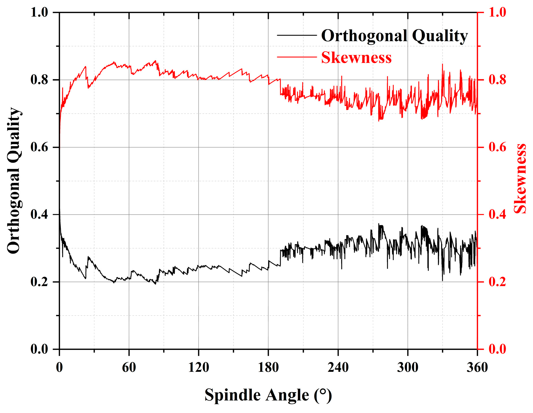
3.1. Mesh Division and Mesh Independence Verification

The three-dimensional fluid domain of the circular involute variable wall thickness scroll expander mainly includes the inlet pipe, storage cavity, suction pipe, working cavity, and exhaust pipe. In the mesh module, we selected CFD for physics preference, and selected the sweep method for the fluid domain. The internal mesh of the working cavity is continuously reconstructed with the rotation of the orbiting scroll. To ensure the quality of the mesh, the free face mesh type was chosen to be all triangles, while a combination of quads and triangles was chosen for the free face mesh of the other cavities [26,27]. The results of the computational fluid domain division are shown in Figure 4, with 713,763 mesh nodes, 860,227 meshes, a maximum skewness of 0.52, and an average element quality of 0.86.
In practical engineering calculations, the computational accuracy does not increase linearly with the number of meshes. Selecting an appropriate number of meshes can effectively improve the calculation efficiency. Therefore, we carried out mesh-independent verification. Figure 5 shows the relationship between the effect of different numbers of meshes on the inlet flow rate and output power under the same constraints and boundary conditions. In the range of 0.5~1.5 million meshes, the inlet flow rate and output power increased by 0.00383 kg/s and 5.731 W, respectively. In the range of 0.5~0.8 million meshes, the inlet flow rate and output power varied greatly, and beyond 0.8 million meshes, the inlet flow rate and output power tended to be stable and the error was maintained within a 5% limit; therefore, 0.86 million meshes appeared to achieve calculation accuracy.

3.2. Dynamic Mesh Technique and Key Parameter Setting

Using the DEFINE_CG_MOTION macro in the Fluent (2021 Version, ANSYS, Inc., Canonsburg, PA, USA, 1970) to control the trajectory of the orbiting scroll, the dynamic mesh method using the spring smooth and 2.5D mesh reconstruction as well as the specific design parameters are shown in Table 2. The orbiting scroll in the working cavity was set as a rigid body, the upper and lower wall surfaces were set as deformation surfaces, the number of time steps was set as 3000 steps, and the time step length was set as 0.0001 s.
The mesh quality evaluation criteria include mesh quality, aspect ratio, skewness, and orthogonal quality. Using the FLUENT, 2021 Version, ANSYS, Inc., Canonsburg, PA, USA, 1970, it is possible to monitor the maximum skewness and the minimum orthogonal quality change at each step of the mesh. To ensure the accuracy of the numerical simulation, the maximum skewness should not be more than 0.95 and the minimum orthogonal quality should not be less than 0.1. If the allowed range is exceeded, abnormal floating points or even negative mesh volumes can occur during the numerical simulation. As shown in Figure 6, due to the change in the position of each grid node of the working cavity driven by the orbiting scroll, the mesh of the three diamond columns was stretched, resulting in an increase in the maximum grid skewness and a decrease in the minimum orthogonal quality. With continuous mesh re-division, the mesh quality improved continuously. In one cycle, the maximum grid skewness and the minimum grid orthogonal quality were maintained below 0.9 and above 0.15, respectively, which satisfied the requirements of mesh calculation.
The density of the working cavity constantly changes as the spindle angle changes. In this paper, the gas in the working cavity was set to be an ideal gas. Because gas properties such as specific heat capacity and thermal conductivity have little effect on compressible flows at low Mach numbers, other gas properties were defined as constants. The specific parameters are shown in Table 3.
The RNG-k-epsilon model based on the reformulated group theory adds parameter terms reflecting the high strain rate flow to the dissipation rate equation, as shown in Equations (10) and (11).
t ( ρ k ) + x i ( ρ k u i ) = x j ( α k μ e f f k x j ) + G k + G b ρ ε Y M + S k
t ( ρ ε ) + x i ( ρ ε u i ) = x j ( α ε μ e f f ε x j ) + G 1 ε ε k ( G k + C 3 ε G b ) C 2 ε ρ ε 2 k + S ε
It was verified through experiments that the RNG-k-epsilon model can reflect a high strain rate and high streamline curvature flow effects with high confidence and accuracy. Therefore, in this paper, the RNG-k-epsilon model was chosen, and the wall function was chosen as the standard wall function. The PISO method was selected for pressure–velocity coupling, and the boundary conditions were set as shown in Table 4.

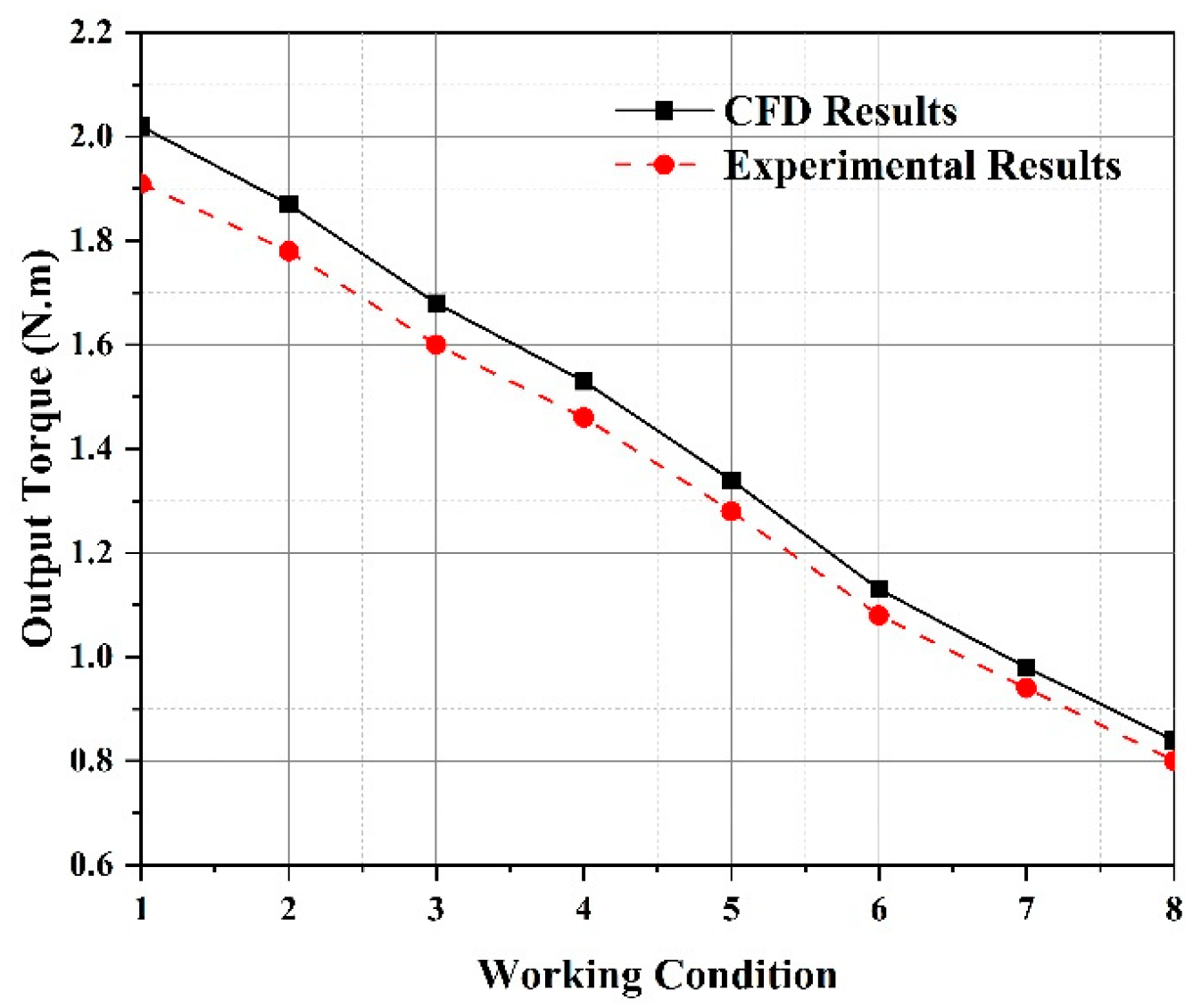
3.3. CFD Numerical Simulation Verification

To verify the reliability of the CFD calculation data, a micro-compressed air energy storage and power generation system test bench was built to conduct the scroll expander performance test. As shown in Figure 7, during the experiment, various types of sensors were used to measure the temperature, pressure, flow rate, output speed, and output torque of the inlet and outlet of the expander.
As shown in Table 5, the actual working conditions of the scroll expander were measured for eight groups of different pressures, temperatures, and speeds to obtain the scroll expander output torque. As shown in Figure 8, the CFD numerical simulation did not take into consideration the friction loss inside the scroll expander, the heat dissipation of the high-pressure gas, or the internal leakage of the expander, which resulted in the CFD calculations being higher than the test results. However, the output torque variation trend of the scroll expander was consistent with the experimental results and the maximum error was 4.8%, which was within the permissible range of error. Therefore, the study method of a scroll expander with CFD numerical simulation was found to be feasible.

4. Data Analysis

4.1. Flow Field Changes

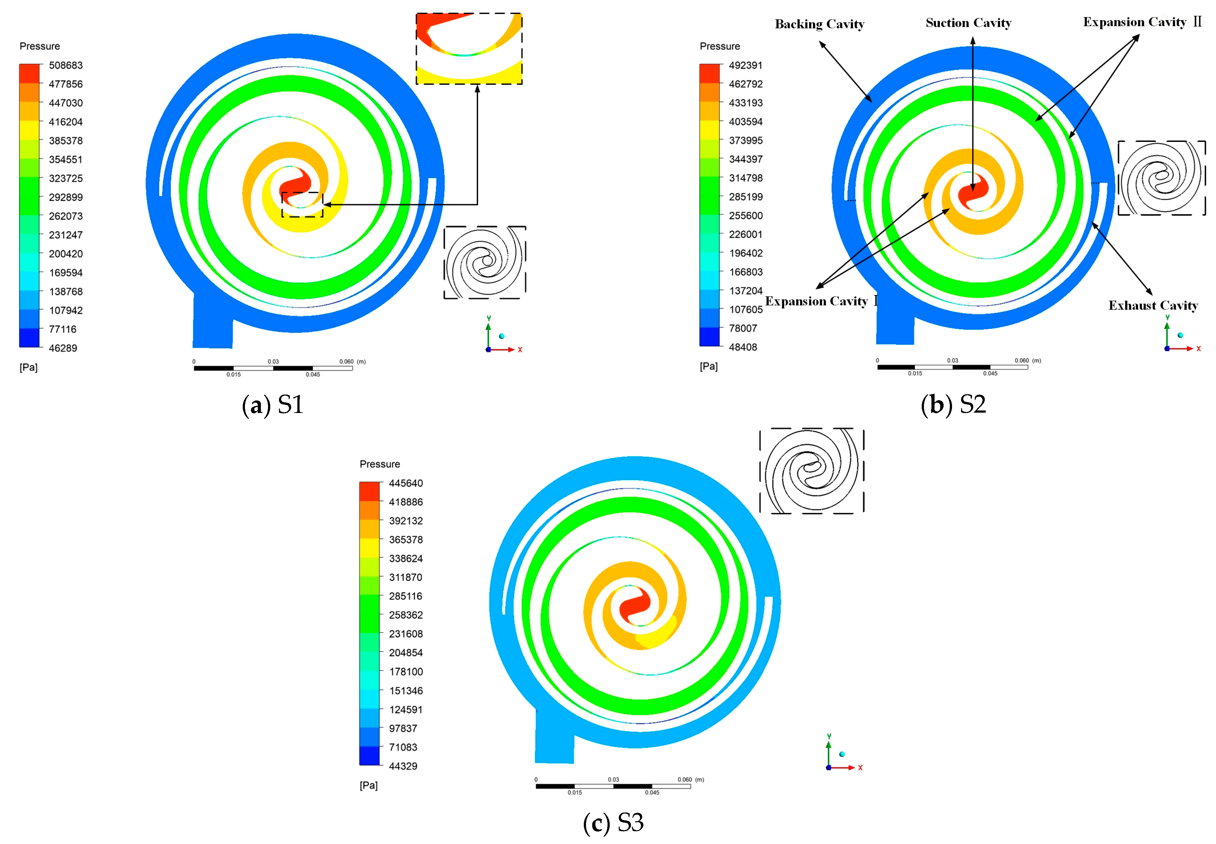
4.1.1. Working Cavity Pressure Field

According to the shape of the air inlet, the circular, elliptical, and double-arc groove are defined as S1, S2, and S3 conditions, respectively. As shown in Figure 9, the working cavity of a circular involute variable wall thickness scroll expander includes a suction cavity, an expansion cavity I, an expansion cavity II, an exhaust cavity, and a back pressure cavity. The pressure in the working cavity decreases gradually from the suction cavity to the exhaust cavity. The pressure at the orbiting and fixed scroll engagement clearance varies sharply, with the overall pressure being high at both ends and low in the middle. Under the action of the pressure of the two adjacent working cavities, there is a tendency for the radial gap at the engagement clearance to become larger, which reduces the working performance of the scroll expander. Due to the inlets in the S1 and S3 conditions not being located in the center of the suction cavity, an uneven pressure division was observed in the symmetric expansion cavity, and the stability of the scroll expander decreased.

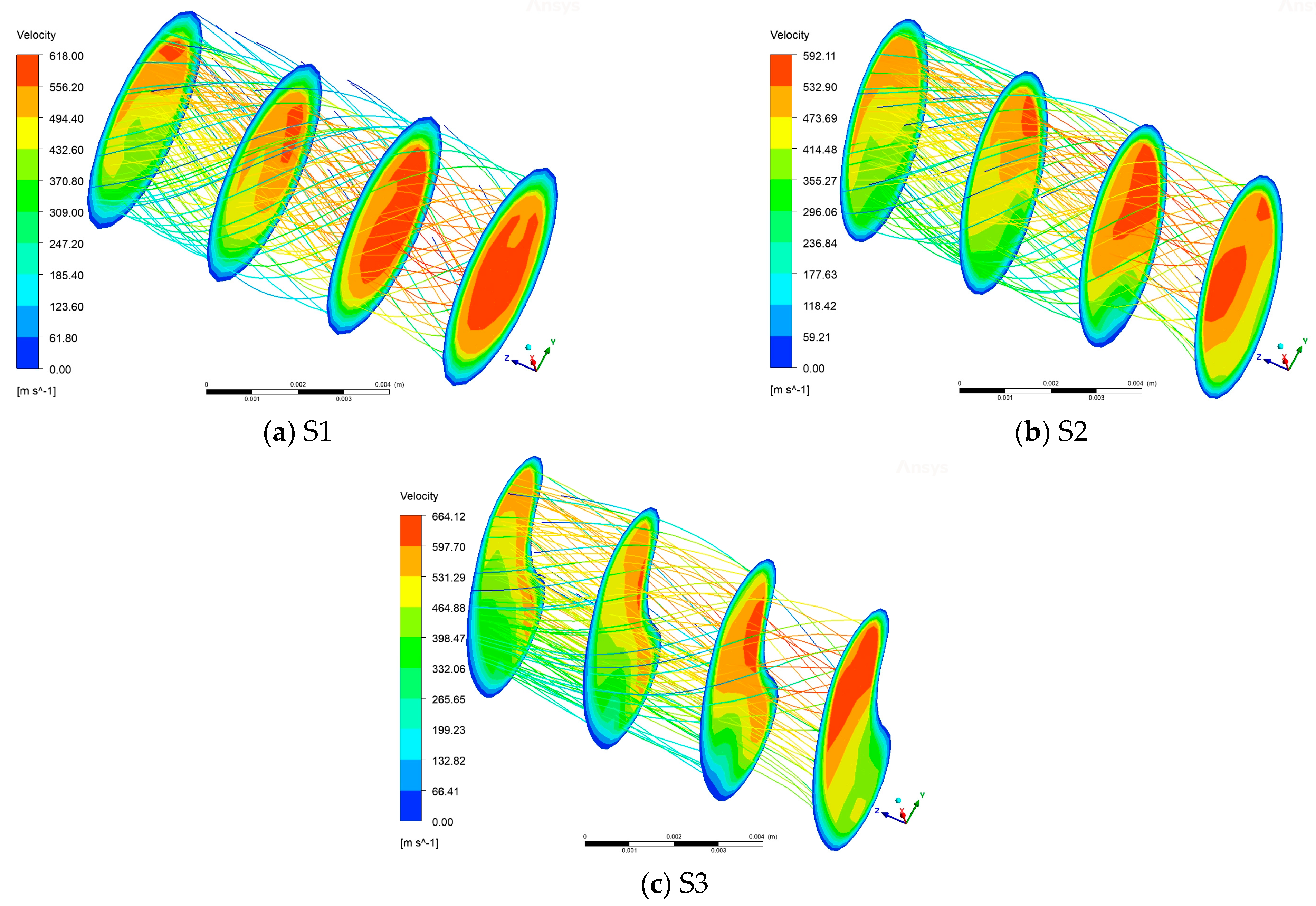
4.1.2. Working Cavity Velocity Field

As shown in Figure 10, the clearance between the two scroll plates engagement was similar to that of the symmetric nozzle model, where the gas flow cross-section changed from large to small, resulting in the maximum flow velocity of the gas at that location. The orbiting scroll of the periodic shading of the suction port resulted in uneven velocity distribution in each working cavity and a large number of swirling phenomena. The swirling phenomena were mainly concentrated in the suction cavity, the expansion cavity, and the back-pressure cavity. Because the tooth head intrusion rates in the S2 and S3 conditions were less than in the S1 condition, the number of fluid impacts on the wall surface of the scroll tooth decreased, and the mechanical loss was reduced. There was a large amount of swirling in the expansion cavities under the three working conditions; this was mainly caused by the fluid energy loss at the wall surface of the scroll teeth and the inconsistency of the fluid movement speed. High-pressure gas flowing in the opposite direction to the backpressure cavity wall in the symmetrical exhaust cavity caused some of the gas to escape from the exhaust pipe, while the other part of the scroll expander along the inner wall of the housing and the fixed scroll teeth of the exhaust end resulted in swirling.

4.1.3. Suction Tube Velocity Field

Figure 11 shows that four sets of planes of the suction pipe were selected at equal intervals to analyze the variations in the internal velocity field. Because gas flow in the suction pipe was not in a single direction, but rather, in a spiral form, the gas constantly hit the wall, resulting in a serious decrease in gas energy. The fluid velocity gradient in the suction pipe was reduced and the velocity distribution was not uniform in each plane. The relative concentration of velocity at the inlet end of the suction pipe, the increase of the gas mass constantly hitting the wall, and collisions among gas molecules led to the fastest decrease of the average fluid velocity in the suction pipe for the S1 condition.

4.2. Output Characteristics

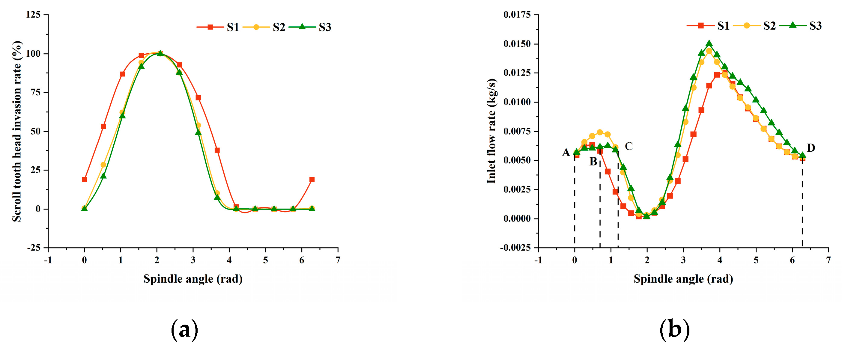
4.2.1. Tooth Head Invasion Rate and Inlet Flow Rate

Figure 12a shows that there was a significant difference in the tooth head invasion rates for the three conditions when the scroll expander was rotated for one cycle. The average tooth head invasion rates were 46%, 36.45%, and 34.68% for S1, S2, and S3, respectively. The average effective air inlet area increased by 9.55% and 11.32% for S2 and S3, compared to S1. As shown in Figure 12b, the inlet flow rate varied more in one cycle due to the periodic shading of the inlet port by the tooth head of the orbiting scroll. From point A to point B, the orbiting scroll tooth head started to shade the inlet; additionally, the inlet velocity of S3 was larger than those of S1 and S2, and the work mass hit the end face of the orbiting scroll tooth head rapidly. As such, the dynamic energy loss was considerable, and the inlet flow rate was smaller than those of the other two conditions. From point B to point C, the inlet flow rate of the S1 condition was less than that of the S3 condition because the effective area of S1 decreased rapidly while the throttling effect of the orbiting scroll tooth head increased. From point C to point D, the effective area of the inlet port of the S3 condition was larger than that of S2, and the inlet flow rate of the S3 condition was larger than that of S2.

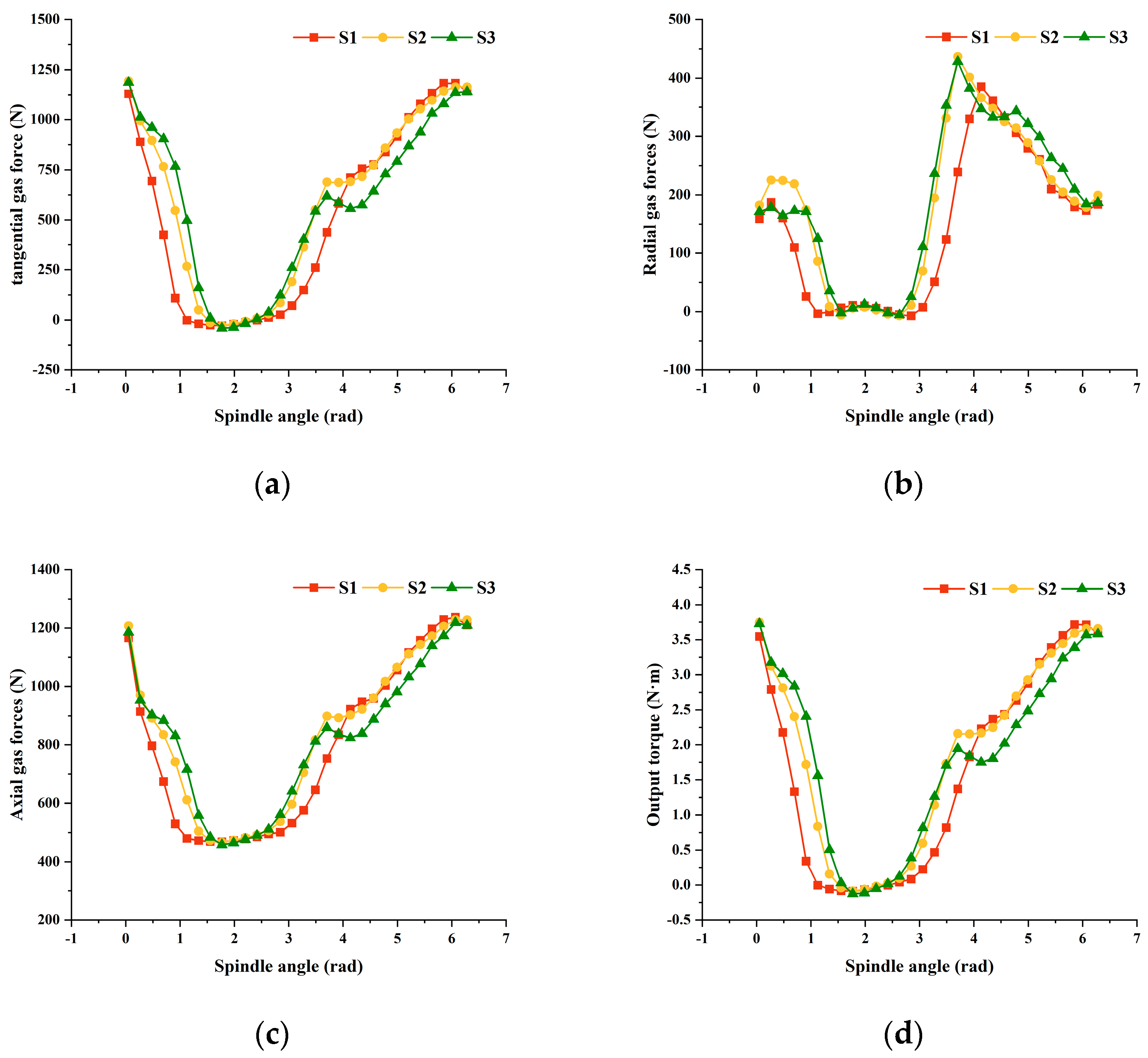
4.2.2. Gas Force and Driving Torque Analysis

As shown in Figure 13, due to the shading of the inlet by the tooth head of the orbiting scroll, the flow rate of the work material changed periodically, resulting in large fluctuations in the change of the gas force and driving torque inside the scroll expander, with an overall trend of decreasing and then increasing. The radial gas force was substantially less than the tangential and axial gas forces for S1, S2, and S3, and the axial gas force was the greatest. The time-averaged tangential forces for S1, S2, and S3 were 487.743 N, 569.859 N, and 557.469 N, respectively, i.e., 16.84% and 14.29% higher for S2 and S3 tangential forces, respectively, compared to S1. The time-averaged radial forces for the S1, S2, and S3 conditions were 140.549 N, 180.194 N, and 186.58 N, respectively, i.e., an increase of 28.21% and 32.75% in radial force for S2 and S3, respectively, compared to S1. The time-averaged axial forces for S1, S2, and S3 were 772.4 N, 815.18 N, and 802.928 N, respectively, i.e., 5.53% and 3.95% higher for S2 and S3 axial forces, respectively, compared to S1. The time-averaged torques for S1, S2, and S3 were 1.53 N·m, 1.78 N·m, and 1.74 N·m, respectively. It was found that the scroll expander output efficiencies for S2 and S3 were better than that of S1.

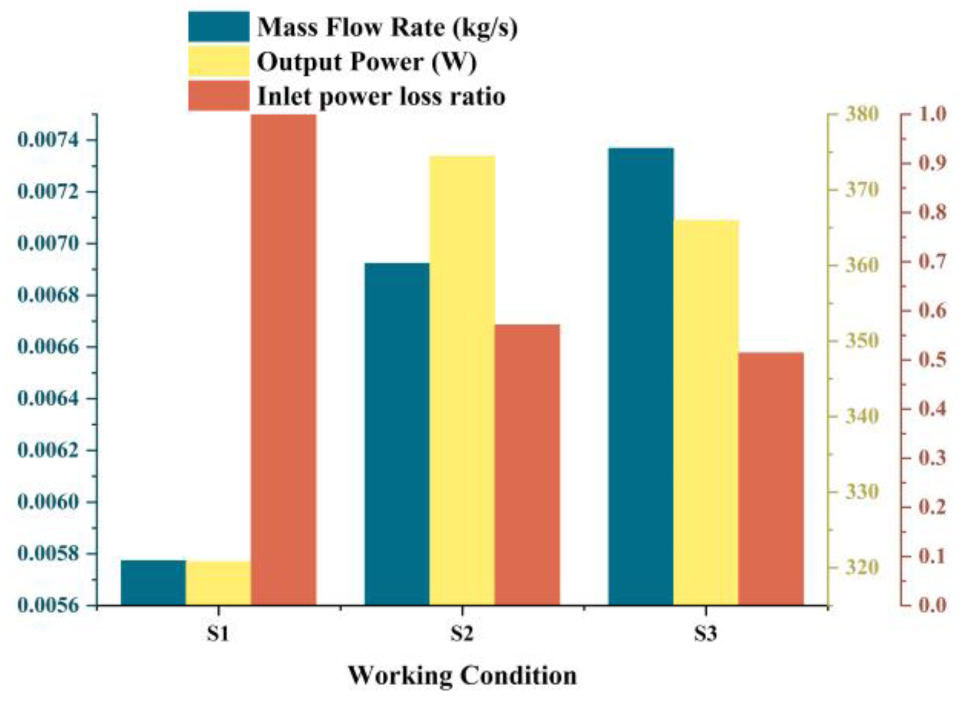
4.2.3. Expander Performance Analysis

The time-averaged inlet flow rate of the scroll expander, the shaft power of the expander, and the ratio of power loss at the inlet for different operating conditions can be seen in Figure 14. The inlet power loss ratios were greater in S2 and S3 than in S1, i.e., the smaller the ratio, the smaller the inlet power loss. As can be seen from the figure, the time-averaged flow rates of S1, S2, and S3 were 0.00577 kg/s, 0.00692 kg/s, and 0.00737 kg/s, respectively. The time-averaged flow rates of S2 and S3 were improved by 19.93% and 27.73%, respectively, compared with S1. The expander shaft power was 320.83 W, 374.43 W, and 365.44 W for S1, S2, and S3, respectively, which was an increase of 16.71% and 13.9% for S2 and S3, respectively, compared to S1. The inlet power loss ratios for S2 and S3 were 0.572 and 0.515, respectively, i.e., reductions in inlet power loss of 42.8% and 48.53% for S2 and S3 compared to S1.
In summary, the elliptical and double-arc groove ports had a larger increase in radial gas force and axial gas force, which may tend to increase leakage within the expander; however, the elliptical and double-arc groove ports were designed to achieve significantly better axial power of the expander than a conventional circular inlet.

5. Conclusions

In this paper, the CFD method was used to numerically simulate a circular involute variable wall thickness scroll expander with circular, elliptical, and double circular arc groove inlets to analyze variations in the flow field, gas force, shaft power, and inlet power loss inside the scroll expander.
(1)
When the air inlet was fully open, the pressure in the working cavity of the scroll expander with elliptical and double circular slotted air inlets was more evenly distributed as compared to a scroll expander with a circular air inlet. Under the joint action of the two adjacent working chambers, the pressure at the engagement clearance of the two scroll plates was low in the middle and high at both ends. Due to the use of scroll expander suction pipe of high-pressure gas in the form of a spiral flowing into the scroll expander suction cavity and the periodic blocking of the scroll teeth, an uneven distribution of the flow rate of each gas workpiece was observed, and the scroll expander working cavity demonstrated significant swirling phenomena.
(2)
The transient inlet flow rate, gas force, and driving torque variations of the scroll expander fluctuated significantly due to the periodic shading of the inlet by the orbiting scroll disc tooth head and the throttling effect on the inlet. The scroll expander had the largest axial gas force and the smallest radial gas force. The driving torque of the scroll expander with double circular groove and elliptical inlet increased by 16.84% and 14.29% compared to the circular inlet, but the axial and radial forces in the scroll expander also increased somewhat, and the leakage tendency in the expander increased.
(3)
The elliptical and double arc groove inlets increased the inlet flow rate by 19.93% and 27.73% relative to the circular inlet while ensuring a certain inlet area when the tooth head was invaded. Compared to the inlet power loss of circular scroll expanders, the inlet power loss of elliptical and double circular groove scroll expanders was reduced by 42.8% and 48.53%. As a result, it was observed that elliptical and double arc groove inlet designs are superior compared to conventional circular inlets, provided that the design requirements are maintained.

Author Contributions

Conceptualization, J.W. (Junying Wei); methodology, X.L.; software, G.L.; validation, J.W. (Junying Wei) and G.L.; formal analysis, J.W. (Junying Wei); investigation, X.L.; resources, J.W. (Junying Wei); data curation, G.L.; writing—original draft preparation, G.L.; writing—review and editing, C.Z.; visualization, W.C.; supervision, J.W. (Jidai Wang); project administration, G.Y.; funding acquisition, J.W. (Junying Wei). All authors have read and agreed to the published version of the manuscript.

Funding

This research was funded by the Provincial Natural Science Foundation of Shandong, grant number ZR2021ME233, ZR202103040075. This research was funded by the Qingdao Emerging Industry Cultivation Program, grant number 22-3-4-xxgg-7-gx.

Data Availability Statement

The datasets used or analysed during the current study are available from the corresponding author on reasonable request.

Acknowledgments

The authors would like to thank the research grant support from the Provincial Natural Science Foundation of Shandong and the Qingdao Emerging Industry Cultivation Program.

Conflicts of Interest

The authors declare no conflict of interest.

Abbreviations

CFDComputational fluid dynamics
ORCOrganic rankine cycle

Nomenclature

A The actual effective area of the air inlet
f The airflow friction factor at the air inlet
ρ The gas density at the air inlet
u The flow rate at the air inlet
n The rotational speed of the orbiting scroll
V The air inlet volume
A 0 The effective area of the air inlet not invaded by the tooth head
F r Radial gas force
F t Tangential gas force
F a Axial gas force
G k The turbulent energy production term due to the time-averaged velocity gradient
G b The turbulent energy production term due to buoyancy
Y M The effect of pulsation expansion on the overall dissipation rate in compressible turbulence
α k The inverse effective Prandtl numbers corresponding to k
α ε The inverse effective Prandtl numbers corresponding to ε
S k , S ε The custom source terms
μ e f f The effective turbulent viscosity.

References

  1. Peng, B.; Yang, B.K.; Gong, K.G.; Zhang, P.C.; Xu, J.W.; Liu, H.X. Research on thermodynamic characteristics and experimental verification of ORC oil-free scroll expander. Therm. Power Gener. 2023, 52, 60–69. [Google Scholar]
  2. Wang, L.; Bu, X.; Li, H. Multi-objective optimization and off-design evaluation of organic rankine cycle (ORC) for low-grade waste heat recovery. Energy 2020, 203, 117809. [Google Scholar] [CrossRef]
  3. Hu, S.; Yang, Z.; Li, J.; Duan, Y. A Review of Multi-Objective Optimization in Organic Rankine Cycle (ORC) System Design. Energies 2021, 14, 6492. [Google Scholar] [CrossRef]
  4. Olabi, A.G.; Wilberforce, T.; Ramadan, M.; Abdelkareem, M.A.; Alami, A.H. Compressed air energy storage systems: Components and operating parameters—A review. J. Energy Storage 2021, 34, 24. [Google Scholar] [CrossRef]
  5. Wei, J.Y.; Hua, Q.; Yuan, L.; Li, G.; Wang, J.H.; Wang, J.D. A review of the research status of scroll expander. Proc. Inst. Mech. Eng. Part A-J. Power Energy 2023, 237, 176–197. [Google Scholar] [CrossRef]
  6. Peng, B.; Li, Y.; Zhao, S. Performance Simulation for Scroll Expanders. China Mech. Eng. 2018, 29, 965–970+978. [Google Scholar]
  7. Feng, Y.Q.; Xu, J.W.; He, Z.X.; Hung, T.C.; Shao, M.; Zhang, F.Y. Numerical simulation and optimal design of scroll expander applied in a small-scale organic rankine cycle. Energy 2022, 260, 124981. [Google Scholar] [CrossRef]
  8. Sun, J.; Peng, B.; Zhu, B.; Li, Y. Research on the performance characteristics of an oil-free scroll expander that is applied to a micro-scale compressed air energy storage system. J. Energy Storage 2023, 63, 106896. [Google Scholar] [CrossRef]
  9. Peng, B.; Zhang, P.C. Mathematical modelling and experimental study of a variable cross-section scroll expander. Mach. Des. Manuf. Eng. 2018, 47, 115–120. [Google Scholar]
  10. Li, X.Q.; Han, Y.; Xi, Z.J.; Li, X.Y.; Wang, J.; Dong, L.N. Design and analysis of mechanical performance of asymmetric variable thickness scroll wraps for scroll compressor. Fluid Mach. 2021, 49, 35–41. [Google Scholar]
  11. Liu, T.; Feng, Z.G.; Sun, Y.J. Equivalent tooth thickness model and geometric performance analysis of IHV variable cross-section scroll profile. Fluid Mach. 2021, 49, 55–61. [Google Scholar]
  12. Hou, C.-S.; Liu, T.; Guo, L.-X. Construction theories of a new type of variable wall thickness scroll profile. J. Jilin Univ. (Eng. Technol. Ed.) 2020, 50, 1627–1634. [Google Scholar]
  13. Emhardt, S.; Tian, G.; Song, P.; Chew, J.; Wei, M. CFD modelling of small scale ORC scroll expanders using variable wall thicknesses. Energy 2020, 199, 117399. [Google Scholar] [CrossRef]
  14. Hao, H.M.; Wu, L.P.; Li, L.; Zou, X.M.; Chen, L.; Chen, X.Y.; Zou, G.Q. Study on Geometric Model of the Combined Cross–Sectional Vortex Expander. Mech. Res. Appl. 2021, 34, 66–68+72. [Google Scholar]
  15. Jia, J.P.; Li, Y.F.; Liu, G.P.; Zhang, G.L.; Li, B. Optimization analysis of the scroll expander specialtop profile correction in the inlet port. J. Mech. Strength 2017, 39, 657–662. [Google Scholar]
  16. Chu, X.G.; Zhang, C.H.; Li, K.; Kong, Y.; Jing, Y.F. Scroll expander modification and test performance study. J. Xi’an Jiaotong Univ. 2014, 48, 37–41+100. [Google Scholar]
  17. Wei, M.; Song, P.; Zhao, B.; Shi, L.; Wang, Z.; Ma, C. Unsteady flow in the suction process of a scroll expander for an ORC waste heat recovery system. Appl. Therm. Eng. 2015, 78, 460–470. [Google Scholar] [CrossRef]
  18. Song, P.P.; Wei, M.S.; Liu, Z.; Zhao, B. Effects of suction port arrangements on a scroll expander for a small scale ORC system based on CFD approach. Appl. Energy 2015, 150, 274–285. [Google Scholar] [CrossRef]
  19. Peng, Z.; Bin, P.; Jie, M. Geometrical modelling analysis of variable cross-section scroll expanders. J. Shanghai Jiaotong Univ. 2023, 57, 309–315. [Google Scholar]
  20. Zhang, P.-C.; Peng, B.; Zhang, Y.-B. Method and theory of establishing variable thickness scrolls based on circle involute. J. Jilin Univ. (Eng. Technol. Ed.) 2022, 52, 789–798. [Google Scholar]
  21. Peng, B.; Jiang, L. Parameter analysis and optimization of modification of tooth head of scroll profile. J. Huazhong Univ. Sci. Technol. (Nat. Sci. Ed.) 2020, 48, 107–112. [Google Scholar]
  22. Wu, Z.; Yan, J.; Xie, F.B.; Zhu, T.; Gao, N.P. Research on the Effect of Suction Port Shape on a Scroll Expander Pressure Loss during the Suction Process. Compress. Technol. 2016, 01, 1–6+12. [Google Scholar]
  23. Song, P. Numerical Investigations on Unsteady Flow of a Scroll Expander for Organic Rankine Cycle. Ph.D. Thesis, School of Mechanical Engineering, Beijing Institute of Technology, Beijng, China, 2015. [Google Scholar]
  24. Liu, Z.; Wei, M.; Song, P.; Emhardt, S.; Tian, G.; Huang, Z. The fluid-thermal-solid coupling analysis of a scroll expander used in an ORC waste heat recovery system. Appl. Therm. Eng. 2018, 138, 72–82. [Google Scholar] [CrossRef]
  25. Wu, Z.; Fang, X.Y.; Zhu, T. Effects of Radial Clearance on Performances of Scroll Expander. Mach. Des. Manuf. 2017, 9, 41–44+48. [Google Scholar]
  26. Liu, Z.; Wu, H.W.; Lin, X.; Song, P.P. Unsteady flows of a scroll expander under various types of expansion process. Energy Storage Sci. Technol. 2019, 8, 1241–1246. [Google Scholar]
  27. Liu, Z.; Wu, H.W.; Hang, J.; Kuang, Y. Numerical investigations on unsteady flow of a scroll expander forcompressed air energy storage. Energy Storage Sci. Technol. 2019, 8, 357–364. [Google Scholar]
Figure 1. Schematic diagram of circular involute variable wall thickness scroll teeth.
Processes 11 03117 g001
Figure 2. Three shapes of air intakes.
Processes 11 03117 g002
Figure 3. Gas force analysis.
Processes 11 03117 g003
Figure 4. Computational domain meshing.
Processes 11 03117 g004
Figure 5. Inlet flow and output power versus the number of meshes.
Processes 11 03117 g005
Figure 6. Maximum skewness and minimum orthogonal quality variation of the working cavity mesh.
Processes 11 03117 g006
Figure 7. Micro-compressed air energy storage and power generation system test bench.
Processes 11 03117 g007
Figure 8. Comparison of simulated and experimental values of expander performance parameters.
Processes 11 03117 g008
Figure 9. Variation of working cavity pressure field.
Processes 11 03117 g009
Figure 10. Velocity field variation in the working cavity.
Processes 11 03117 g010
Figure 11. Velocity field variation in the suction tube.
Processes 11 03117 g011
Figure 12. Variation of transient parameters of scroll expander imports. (a) Tooth head invasion rate (b) Inlet flow rate.
Processes 11 03117 g012
Figure 13. Variation of transient gas force and driving torque of the orbiting scroll. (a) Tangential gas force, (b) Radial gas force, (c) Axial gas force, and (d) Drive torque.
Processes 11 03117 g013
Figure 14. Comparison of performance under different working conditions.
Processes 11 03117 g014
Table 1. Design parameters.
Parameter NameSymbolicValueUnit
Base circle radius R 1 2 mm
R 2 4 mm
Involute incidence angle α 0.785 rad
Turning radius R o r 3.14 mm
Involute angle φ 1 2 π rad
φ 2 4 π rad
φ 3 6 π rad
Involute end angle φ e 7.5 π rad
Median value θ M π rad
Number of laps n 1 2
n 2 1
Table 2. Dynamic mesh design parameters.
Spring SettingParametersMethods-Based RemeshingParameters
Spring Constant Factor0.1Minimum Length Scale0.1 mm
Convergence Tolerance0.001Maximum Length Scale1 mm
Maximum Number of Iterations20Maximum Cell Skewness0.8
ElementsTet in Tet ZonesMaximum Face Skewness0.7
Laplace Node Relaxation1Size Remeshing Interval1
Table 3. Fluid Property Settings.
Parameter NameValueUnit
DensityIdeal gaskg/m3
Specific Heat Capacity1006.43J/kg·K
Coefficient of Thermal Conductivity0.0242W/m·K
Viscosity1.7894 × 10−5kg/(m·s)
Relative molecular mass28.966kg/kmol
Table 4. Boundary condition settings.
TypesFluid MaterialsPressureTemperature
Pressure-inletAir0.7 Mpa373 K
Pressure-outletAir0.1 Mpa300 K
Table 5. Simulated working conditions.
Working ConditionInlet Pressure/MpaInlet Temperature/KOutlet Pressure/MpaOutlet Temperature/KRotation Speed/rpm
10.75296.980.30292.101203
20.70296.800.28289.841177
30.65296.790.25289.151103
40.60296.75022288.821036
50.55296.590.20289.81989
60.50296.620.17289.11872
70.45296.580.15289.56807
80.40296.530.13290.19733
Disclaimer/Publisher’s Note: The statements, opinions and data contained in all publications are solely those of the individual author(s) and contributor(s) and not of MDPI and/or the editor(s). MDPI and/or the editor(s) disclaim responsibility for any injury to people or property resulting from any ideas, methods, instructions or products referred to in the content.

