Optimization of Heat Recovery Networks for Energy Savings in Industrial Processes
Abstract
1. Introduction
2. Problem Statement
3. Model Formulation
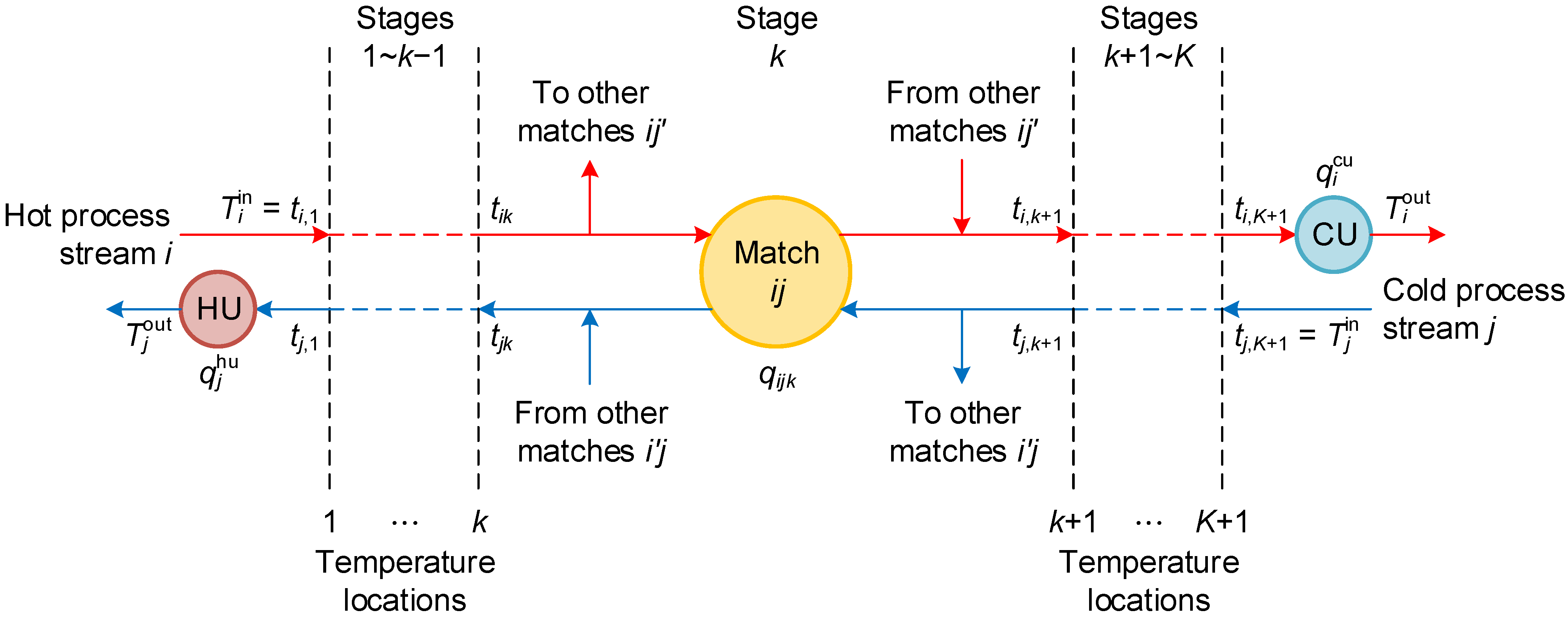
3.1. Overall Energy Balance for Process Streams
3.2. Energy Balance for Process Streams in Each Stage
3.3. Temperature Assignment and Feasibility Constraints
3.4. Utility Requirements and Latent Heat Balance
3.5. Feasibility of Latent Heat Exchange
3.6. Logical Constraints and Temperature Differences
3.7. Objective Function
4. Industrial Case Study
4.1. Preliminary Analysis
- No stream splitting is allowed;
- Any pair of hot and cold process streams has at most one match throughout the superstructure;
- The condenser, evaporator and reboiler streams each have at most one match with other process streams.
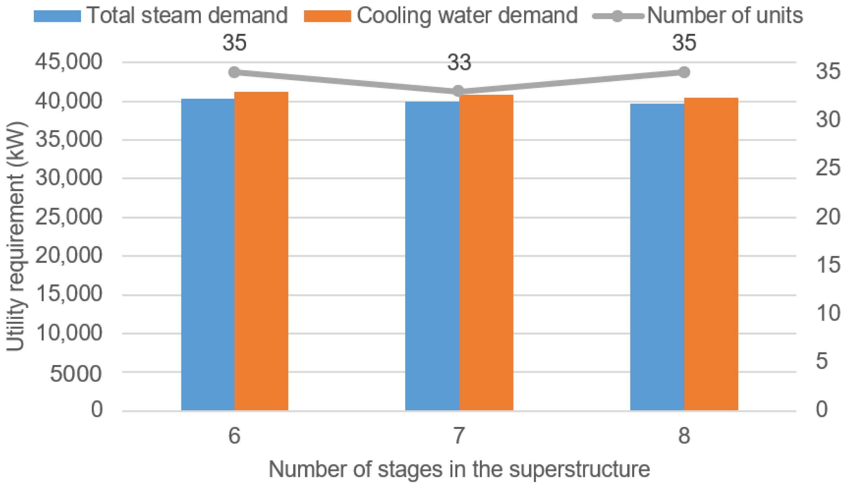
4.2. Analysis without Condensers, Evaporator and Reboilers
- No stream splitting is allowed (Equations (31) and (32));
- Any pair of hot and cold process streams has at most one match (Equation (33)).
5. Conclusions
Supplementary Materials
Author Contributions
Funding
Institutional Review Board Statement
Informed Consent Statement
Data Availability Statement
Acknowledgments
Conflicts of Interest
Appendix A. Nomenclature
Appendix A.1. Indices and Sets
| process hot streams | |
| process hot streams involving only sensible heat | |
| process hot streams involving only latent heat | |
| process hot streams involving both sensible and latent heat | |
| process cold streams | |
| process cold streams involving only sensible heat | |
| process cold streams involving only latent heat | |
| process cold streams involving both sensible and latent heat | |
| temperature locations | |
| stages |
Appendix A.2. Parameters
| heat capacity of hot process stream i (J/g/°C) | |
| heat capacity of cold process stream j (J/g/°C) | |
| flowrate of hot process stream i (t/h) | |
| flowrate of cold process stream j (t/h) | |
| upper limit to the heat transfer from hot process stream i (kW) | |
| upper limit to the heat transfer from hot process stream i to cold process stream | |
| upper limit to the heat transfer to cold process stream j (kW) | |
| outlet temperature of the cold utility (°C) | |
| outlet temperature of the hot utility (°C) | |
| inlet temperature of hot process stream i (°C) | |
| outlet temperature of hot process stream i (°C) | |
| inlet temperature of cold process stream j (°C) | |
| outlet temperature of cold process stream j (°C) | |
| phase change fraction of hot process stream i | |
| phase change fraction of cold process stream j | |
| minimum temperature difference for hot utility-process matches (°C) | |
| minimum temperature difference for process-cold utility matches (°C) | |
| minimum temperature difference for process-process matches (°C) | |
| a sufficiently small value (°C) | |
| latent heat of hot process stream i (J/g) | |
| latent heat of cold process stream j (J/g) | |
| a sufficiently large value (°C) |
Appendix A.3. Variables
| cold utility requirement for hot process stream i (kW) | |
| condensation heat load of hot process stream i in the cooler (kW) | |
| heat transfer from hot process stream i to cold process stream j in stage k (kW) | |
| condensation heat load of hot process stream i in stage k (kW) | |
| evaporation heat load of cold process stream j in the heater (kW) | |
| hot utility requirement for cold process stream j (kW) | |
| evaporation heat load of cold process stream j in stage k (kW) | |
| temperature of cold process stream j at temperature location k (°C) | |
| binary indicating if the inlet temperature of hot process stream i at stage k is greater than or equal to the condensation temperature | |
| binary indicating if the outlet temperature of cold process stream j at stage k is greater than or equal to the evaporation temperature | |
| binary indicating if hot process stream i uses the cold utility | |
| binary indicating if hot process stream i transfers heat to cold process stream j in stage k | |
| binary indicating if cold process stream j uses the hot utility |
References
- International Energy Agency (IEA). Net Zero by 2050: A Roadmap for the Global Energy Sector; IEA: Paris, France, 2021. [Google Scholar]
- Klemeš, J.J.; Kravanja, Z. Forty years of Heat Integration: Pinch Analysis (PA) and Mathematical Programming (MP). Curr. Opin. Chem. Eng. 2013, 2, 461–474. [Google Scholar] [CrossRef]
- Kemp, I.C. Pinch Analysis and Process Integration: A User Guide on Process Integration for the Efficient Use of Energy, 2nd ed.; Butterworth-Heinemann: Oxford, UK, 2007. [Google Scholar]
- Yee, T.F.; Grossmann, I.E. Simultaneous optimization models for heat integration—II. Heat exchanger network synthesis. Comput. Chem. Eng. 1990, 14, 1165–1184. [Google Scholar] [CrossRef]
- Huang, K.F.; Karimi, I.A. Simultaneous synthesis approaches for cost-effective heat exchanger networks. Chem. Eng. Sci. 2013, 98, 231–245. [Google Scholar] [CrossRef]
- Beck, A.; Hofmann, R. A novel approach for linearization of a MINLP stage-wise superstructure formulation. Comput. Chem. Eng. 2018, 112, 17–26. [Google Scholar] [CrossRef]
- Ziyatdinov, N.N.; Emel’yanov, I.I.; Chen, Q.; Grossmann, I.E. Optimal heat exchanger network synthesis by sequential splitting of process streams. Comput. Chem. Eng. 2020, 142, 107042. [Google Scholar] [CrossRef]
- Liu, Z.; Yang, L.; Yang, S.; Qian, Y. An extended stage-wise superstructure for heat exchanger network synthesis with intermediate placement of multiple utilities. Energy 2022, 248, 123372. [Google Scholar] [CrossRef]
- Čuček, L.; Boldyryev, S.; Klemeš, J.J.; Kravanja, Z.; Krajačić, G.; Varbanov, P.S.; Duić, N. Approaches for retrofitting heat exchanger networks within processes and Total Sites. J. Clean. Prod. 2019, 211, 884–894. [Google Scholar] [CrossRef]
- Pavão, L.V.; Costa, C.B.B.; Ravagnani, M.A.S.S. Heat exchanger networks retrofit with an extended superstructure model and a meta-heuristic solution approach. Comput. Chem. Eng. 2019, 125, 380–399. [Google Scholar] [CrossRef]
- Cheng, S.-L.; Chang, C.-T.; Jiang, D. A game-theory based optimization strategy to configure inter-plant heat integration schemes. Chem. Eng. Sci. 2014, 118, 60–73. [Google Scholar] [CrossRef]
- Nair, S.K.; Guo, Y.; Mukherjee, U.; Karimi, I.A.; Elkamel, A. Shared and practical approach to conserve utilities in eco-industrial parks. Comput. Chem. Eng. 2016, 93, 221–233. [Google Scholar] [CrossRef]
- Kachacha, C.; Farhat, A.; Zoughaib, A.; Tran, C.T. Site wide heat integration in eco-industrial parks considering variable operating conditions. Comput. Chem. Eng. 2019, 126, 304–320. [Google Scholar] [CrossRef]
- Pavão, L.V.; Miranda, C.B.; Costa, C.B.B.; Ravagnani, M.A.S.S. Efficient multiperiod heat exchanger network synthesis using a meta-heuristic approach. Energy 2018, 142, 356–372. [Google Scholar] [CrossRef]
- Hofmann, R.; Panuschka, S.; Beck, A. A simultaneous optimization approach for efficiency measures regarding design and operation of industrial energy systems. Comput. Chem. Eng. 2019, 128, 246–260. [Google Scholar] [CrossRef]
- Ibrić, N.; Ahmetović, E.; Kravanja, Z. Simultaneous optimization of water and energy within integrated water networks. Appl. Therm. Eng. 2014, 70, 1097–1122. [Google Scholar] [CrossRef]
- Ibrić, N.; Ahmetović, E.; Kravanja, Z.; Maréchal, F.; Kermani, M. Simultaneous synthesis of non-isothermal water networks integrated with process streams. Energy 2017, 141, 2587–2612. [Google Scholar] [CrossRef]
- Huang, K.; Karimi, I.A. Work-heat exchanger network synthesis (WHENS). Energy 2016, 113, 1006–1017. [Google Scholar] [CrossRef]
- Li, J.; Demirel, S.E.; Hasan, M.M.F. Building Block-Based Synthesis and Intensification of Work-Heat Exchanger Networks (WHENS). Processes 2019, 7, 23. [Google Scholar] [CrossRef]
- Vikse, M.; Watson, H.A.J.; Barton, P.I.; Gundersen, T. Nonsmooth formulation for handling unclassified process streams in the optimization of work and heat exchange networks. Ind. Eng. Chem. Res. 2019, 58, 9526–9539. [Google Scholar] [CrossRef]
- Yang, R.; Zhuang, Y.; Zhang, L.; Du, J.; Shen, S. A thermo-economic multi-objective optimization model for simultaneous synthesis of heat exchanger networks including compressors. Chem. Eng. Res. Des. 2020, 153, 120–135. [Google Scholar] [CrossRef]
- Hamedi, H.; Karimi, I.A.; Gundersen, T. Simulation-based approach for integrating work within heat exchange networks for sub-ambient processes. Energy Convers. Manag. 2020, 203, 112276. [Google Scholar] [CrossRef]
- Li, M.; Zhuang, Y.; Li, W.; Dong, Y.; Zhang, L.; Du, J.; Shen, S. A surrogate-based optimization framework for simultaneous synthesis of chemical process and heat exchanger network. Chem. Eng. Res. Des. 2021, 170, 180–188. [Google Scholar] [CrossRef]
- Ponce-Ortega, J.M.; Jiménez-Gutiérrez, A.; Grossmann, I.E. Optimal synthesis of heat exchanger networks involving isothermal process streams. Comput. Chem. Eng. 2008, 32, 1918–1942. [Google Scholar] [CrossRef]
- Watanapanich, S.; Li, S.-T.; Lee, J.-Y. Optimal integration of organic Rankine cycles into process heat exchanger networks: A simultaneous approach. Energy Convers. Manag. 2022, 260, 115604. [Google Scholar] [CrossRef]
- Syu, J.-R. (R & D Center, Nan Ya Plastics Corporation, New Taipei City, Taiwan); Lee, Y.-C. (R & D Center, Nan Ya Plastics Corporation, New Taipei City, Taiwan). Personal communication, 2022.
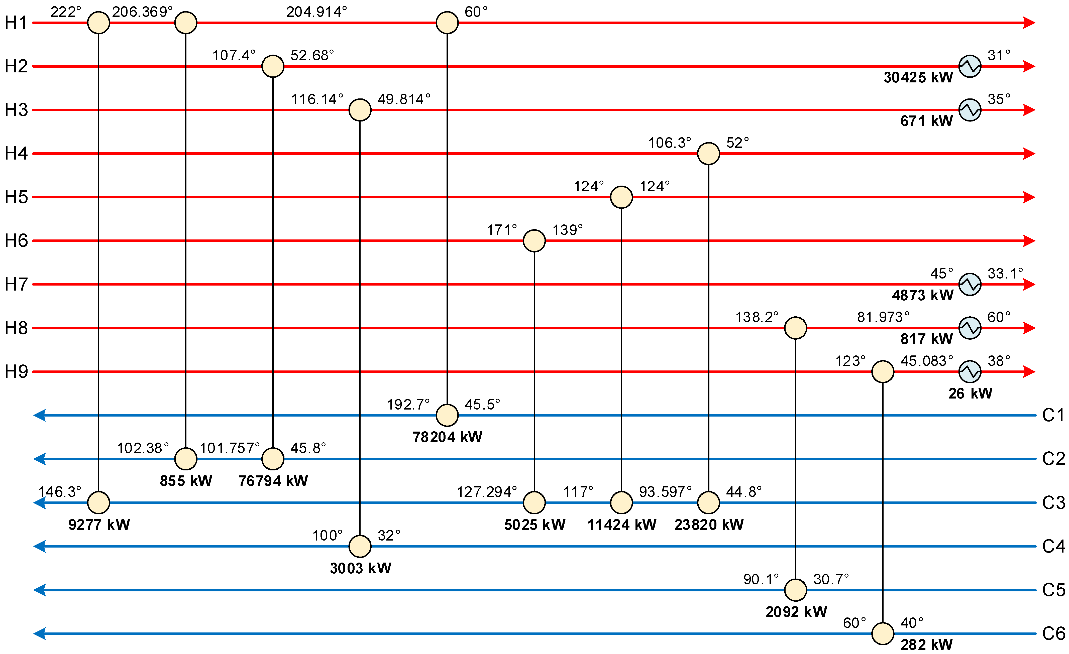
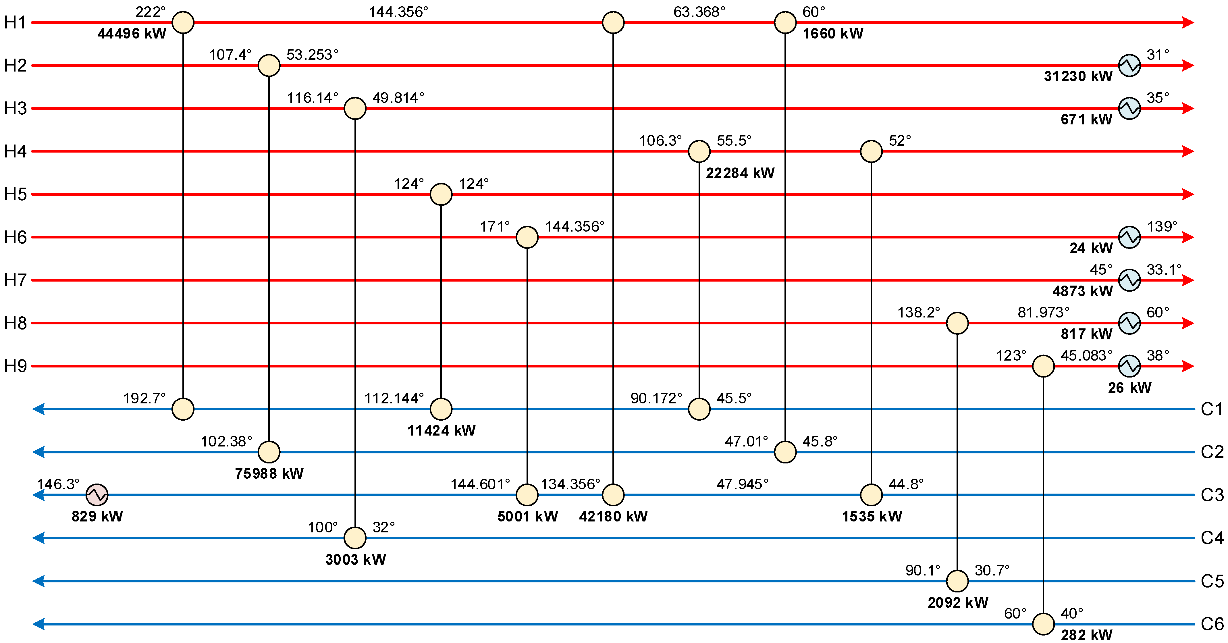
| Stream | Description | Flowrate (t/h) | Inlet Temperature (°C) | Outlet Temperature (°C) | Heat Capacity (J/g/°C) | Latent Heat (J/g) | Phase Change Fraction |
|---|---|---|---|---|---|---|---|
| H1 | Outlet recycle gas | 981 | 220 | 60 | 2.11 | - | 0 |
| H2 | Recycled water | 1150 | 107.4 | 31 | 4.118 | - | 0 |
| H3 | Recycled water | 37.1 | 116.1 | 35 | 4.118 | - | 0 |
| H4 | Process condensate | 347 | 106.3 | 52 | 4.226 | - | 0 |
| H5 | Process vapor | 17.4 | 124 | 124 | - | 2194.508 (at 124 °C) | 1 |
| H6 | Process vapor | 7.8 | 171 | 139 | 1.925 | 2092 (at 171 °C) | 1 |
| H7 | Absorbent | 354.1 | 45 | 33.1 | 4.163 | - | 0 |
| H8 | MEG product | 48.5 | 138 | 60 | 2.761 | - | 0 |
| H9 | DEG product | 5.1 | 123 | 38 | 2.552 | - | 0 |
| H10 | Water vapor | 13.5 | 61 | 40 | 4.184 | 2397.432 (at 61 °C) | 1 |
| H11 | Glycol vapor | 1.2 | 130 | 43 | 2.741 | 1125.496 (at 130 °C) | 1 |
| H12 | Glycol vapor | 5.1 | 92 | 60 | 2.678 | 962.32 (at 92 °C) | 1 |
| H13 | Glycol vapor | 10.9 | 147 | 120.5 | 2.72 | 627.6 (at 147 °C) | 1 |
| H14 | Glycol vapor | 2.2 | 152 | 139 | 2.761 | 589.944 (at 152 °C) | 1 |
| Stream | Description | Flowrate (t/h) | Inlet Temperature (°C) | Outlet Temperature (°C) | Heat Capacity (J/g/°C) | Latent Heat (J/g) | Phase Change Fraction |
|---|---|---|---|---|---|---|---|
| C1 | Inlet recycle gas | 981 | 45.5 | 192.5 | 1.979 | - | 0 |
| C2 | Recycled water | 1189.2 | 45.8 | 102.4 | 4.118 | - | 0 |
| C3 | EO solution | 400 | 44.8 | 146.3 | 4.079 | - | 0 |
| C4 | Recycled water | 35.44 | 32 | 100 | 4.226 | - | 0 |
| C5 | Process condensate | 30 | 30.7 | 90.1 | 4.226 | - | 0 |
| C6 | Process condensate | 12 | 40 | 60 | 4.226 | - | 0 |
| C7 | EG solution | 40.03 | 186.4 | 186.4 | - | 1966.48 (at 186.4 °C) | 1 |
| C8 | Glycol mixture | 25.03 | 134 | 134 | - | 874.456 (at 134 °C) | 1 |
| C9 | Glycol mixture | 341.2 | 163.3 | 170 | 2.954 | 782.408 (at 170 °C) | 0.2 |
| C10 | Glycol mixture | 151.02 | 171.5 | 179.2 | 2.889 | - | 0 |
| C11 | Glycol mixture | 283.221 | 167.5 | 172.1 | 2.933 | - | 0 |
| C12 | Glycol mixture | 53.64 | 161.8 | 163.9 | 2.964 | - | 0 |
| Stream | C1 | C2 | C3 | C4 | C5 | C6 | C7 | C8 | C9 | C10 | C11 | C12 | Cooling Water |
|---|---|---|---|---|---|---|---|---|---|---|---|---|---|
| H1 | 79,275 | 12,742 | |||||||||||
| H2 | 64,257 | 36,253 | |||||||||||
| H3 | 2829 | 615 | |||||||||||
| H4 | 22,118 | ||||||||||||
| H5 | 10,607 | ||||||||||||
| H6 | 4534 | ||||||||||||
| H7 | 4873 | ||||||||||||
| H8 | 2092 | 810 | |||||||||||
| H9 | 282 | 26 | |||||||||||
| H10 | 9292 | ||||||||||||
| H11 | 448 | ||||||||||||
| H12 | 1493 | ||||||||||||
| H13 | 2127 | ||||||||||||
| H14 | 389 | ||||||||||||
| 180 °C steam | 8748 | 6080 | 93 | ||||||||||
| 213 °C steam | 21,866 | 16,707 | 933 | 1061 |
| Stream | C1 | C2 | C3 | C4 | C5 | C6 | C7 | C8 | C9 | C10 | C11 | C12 | Cold Utility |
|---|---|---|---|---|---|---|---|---|---|---|---|---|---|
| H1 | 10 | 10 | 10 | 10 | 10 | 10 | 10 | 10 | 10 | 10 | 10 | 10 | 5 |
| H2 | 10 | 3.39 | 10 | 10 | 10 | 10 | 10 | 10 | 10 | 10 | 10 | 10 | 2 |
| H3 | 10 | 10 | 10 | 10 | 10 | 10 | 10 | 10 | 10 | 10 | 10 | 10 | 3 |
| H4 | 10 | 10 | 7.2 | 10 | 10 | 10 | 10 | 10 | 10 | 10 | 10 | 10 | 5 |
| H5 | 10 | 10 | 5 | 10 | 10 | 10 | 10 | 10 | 10 | 10 | 10 | 10 | 5 |
| H6 | 10 | 10 | 10 | 10 | 10 | 10 | 10 | 10 | 10 | 10 | 10 | 10 | 5 |
| H7 | 10 | 10 | 10 | 10 | 10 | 10 | 10 | 10 | 10 | 10 | 10 | 10 | 4 |
| H8 | 10 | 10 | 10 | 10 | 10 | 10 | 10 | 10 | 10 | 10 | 10 | 10 | 15 |
| H9 | 10 | 10 | 10 | 10 | 10 | 5 | 10 | 10 | 10 | 10 | 10 | 10 | 6 |
| H10 | 10 | 10 | 10 | 10 | 10 | 10 | 10 | 10 | 10 | 10 | 10 | 10 | 10 |
| H11 | 10 | 10 | 10 | 10 | 10 | 10 | 10 | 10 | 10 | 10 | 10 | 10 | 10 |
| H12 | 10 | 10 | 10 | 10 | 10 | 10 | 10 | 10 | 10 | 10 | 10 | 10 | 27 |
| H13 | 10 | 10 | 10 | 10 | 10 | 10 | 10 | 10 | 10 | 10 | 10 | 10 | 89 |
| H14 | 10 | 10 | 10 | 10 | 10 | 10 | 10 | 10 | 10 | 10 | 10 | 10 | 106 |
| Hot utility | 10 | 10 | 33.7 | 10 | 10 | 10 | 21 | 42 | 33 | 28 | 17 | 15 | - |
| Stream | C1 | C2 | C3 | C4 | C5 | C6 | C7 | C8 | C9 | C10 | C11 | C12 | Cooling Water |
|---|---|---|---|---|---|---|---|---|---|---|---|---|---|
| H1 | 46,223 | 12,374 | 482 | 10,151 | 6080 | 16,707 | |||||||
| H2 | 75,135 | 25,374 | |||||||||||
| H3 | 2346 | 98 | 999 | ||||||||||
| H4 | 22,118 | ||||||||||||
| H5 | 10,607 | ||||||||||||
| H6 | 4508 | 27 | |||||||||||
| H7 | 4873 | ||||||||||||
| H8 | 908 | 1994 | |||||||||||
| H9 | 282 | 26 | |||||||||||
| H10 | 9292 | ||||||||||||
| H11 | 344 | 103 | |||||||||||
| H12 | 1493 | ||||||||||||
| H13 | 1956 | 171 | |||||||||||
| H14 | 379 | 10 | |||||||||||
| 180 °C steam | 26,209 | 93 | |||||||||||
| 213 °C steam | 11,715 | 933 | 1061 |
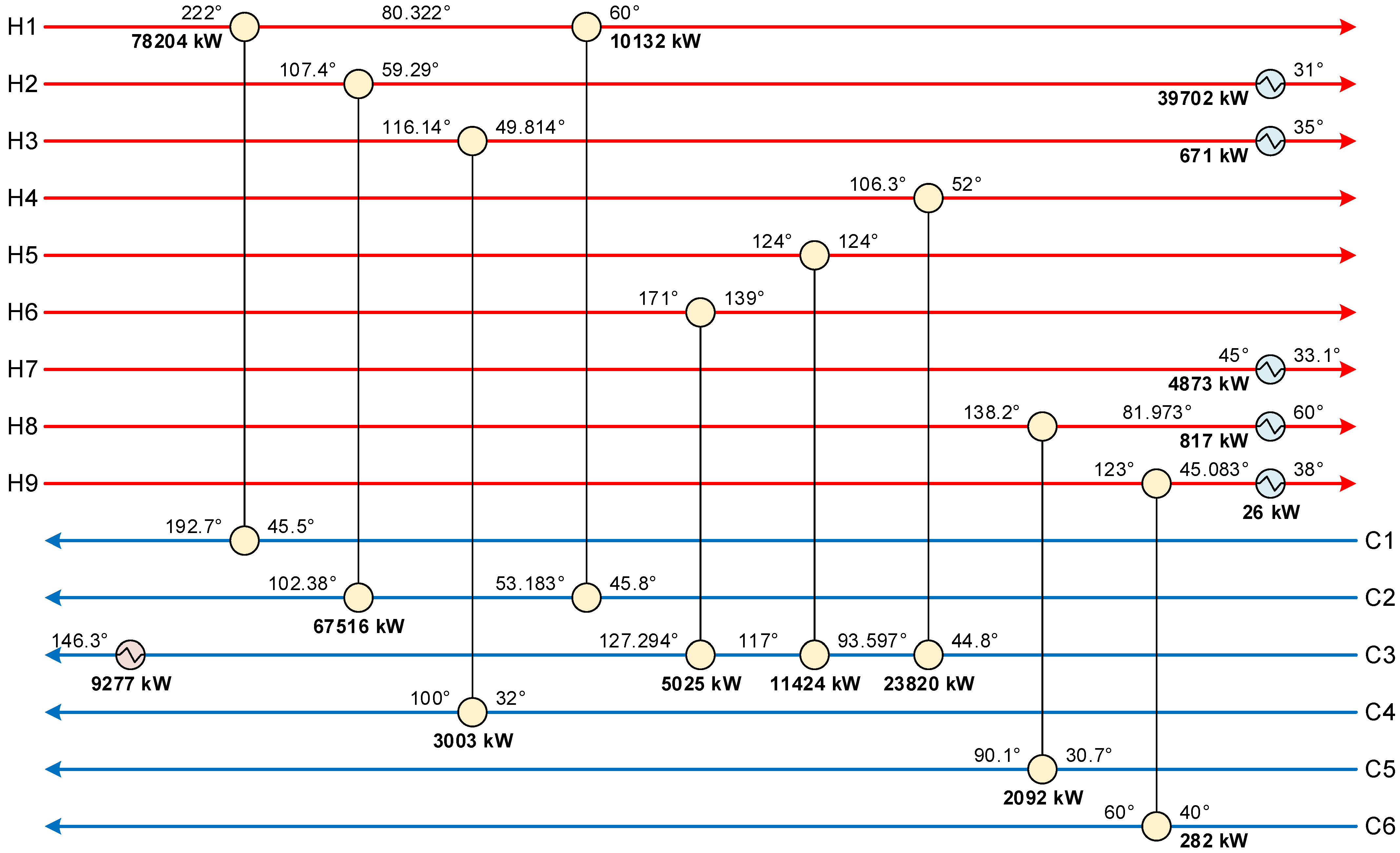
| Stream | Description | Flowrate (t/h) | Inlet Temperature (°C) | Outlet Temperature (°C) | Heat Capacity (J/g/°C) | Latent Heat (J/g) | Phase Change Fraction |
|---|---|---|---|---|---|---|---|
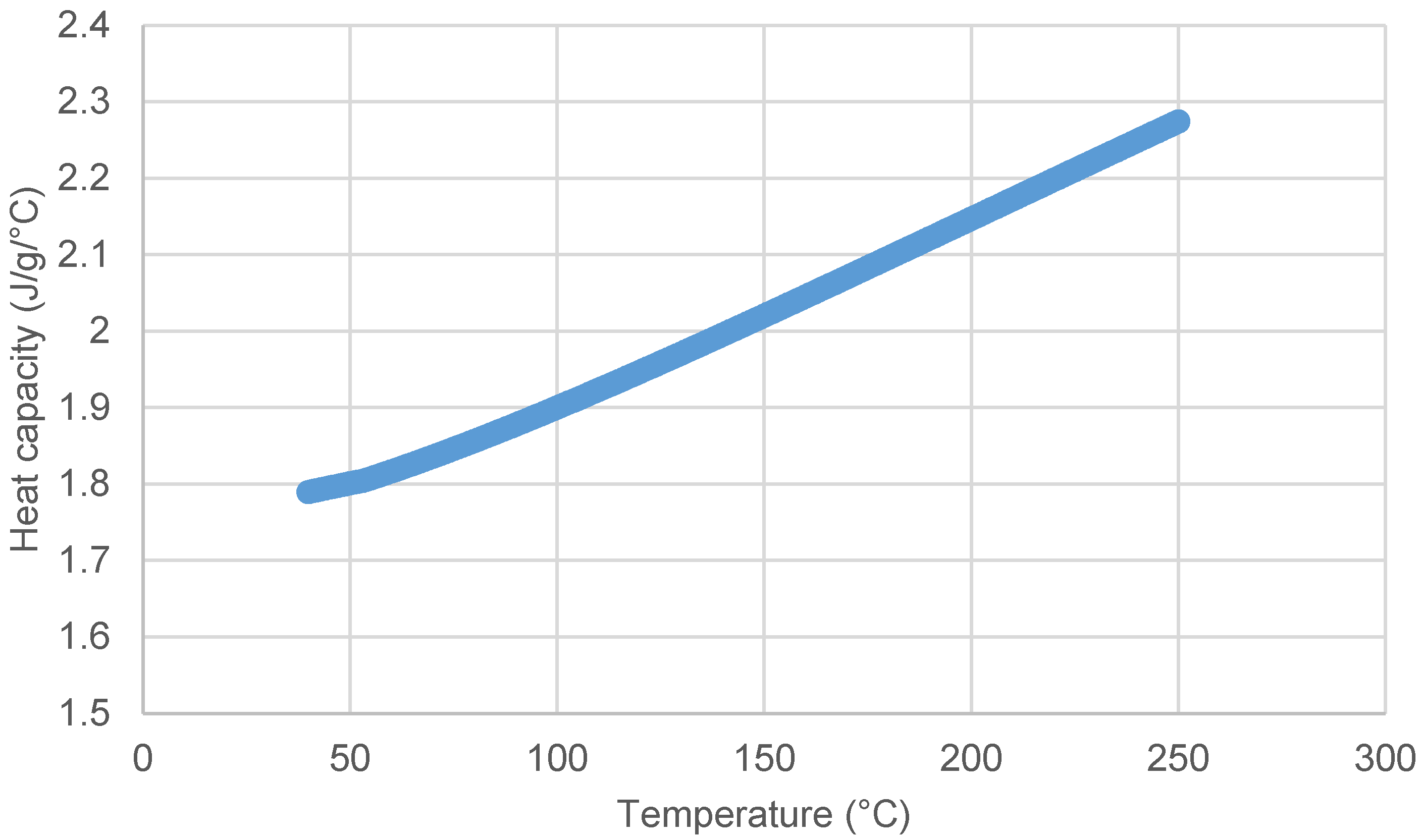
| H1 | Outlet recycle gas | 981 | 222 | 60 | fH1(T) | - | 0 |
| H2 | Recycled water | 1150 | 107.4 | 31 | 4.393 | - | 0 |
| H3 | Recycled water | 37.1 | 116.14 | 35 | 4.393 | - | 0 |
| H4 | Process condensate | 373.7 | 106.3 | 52 | 4.226 | - | 0 |
| H5 | Process vapor | 18.74 | 124 | 124 | - | 2194.508 (at 124 °C) | 1 |
| H6 | Process vapor | 8.4 | 171 | 139 | 1.925 | 2092 (at 171 °C) | 1 |
| H7 | Absorbent | 354.1 | 45 | 33.1 | 4.163 | - | 0 |
| H8 | MEG product | 48.5 | 138.2 | 60 | 2.761 | - | 0 |
| H9 | DEG product | 5.1 | 123 | 38 | 2.552 | - | 0 |
| C1 | Inlet recycle gas | 981 | 45.5 | 192.7 | fC1(T) | - | 0 |
| C2 | Recycled water | 1189.2 | 45.8 | 102.38 | 4.155 | - | 0 |
| C3 | EO solution | 400 | 44.8 | 146.3 | 4.393 | - | 0 |
| C4 | Recycled water | 37.62 | 32 | 100 | 4.226 | - | 0 |
| C5 | Process condensate | 30 | 30.7 | 90.1 | 4.226 | - | 0 |
| C6 | Process condensate | 12 | 40 | 60 | 4.226 | - | 0 |
Disclaimer/Publisher’s Note: The statements, opinions and data contained in all publications are solely those of the individual author(s) and contributor(s) and not of MDPI and/or the editor(s). MDPI and/or the editor(s) disclaim responsibility for any injury to people or property resulting from any ideas, methods, instructions or products referred to in the content. |
© 2023 by the authors. Licensee MDPI, Basel, Switzerland. This article is an open access article distributed under the terms and conditions of the Creative Commons Attribution (CC BY) license (https://creativecommons.org/licenses/by/4.0/).
Share and Cite
Lee, J.-Y.; Chen, P.-Y. Optimization of Heat Recovery Networks for Energy Savings in Industrial Processes. Processes 2023, 11, 321. https://doi.org/10.3390/pr11020321
Lee J-Y, Chen P-Y. Optimization of Heat Recovery Networks for Energy Savings in Industrial Processes. Processes. 2023; 11(2):321. https://doi.org/10.3390/pr11020321
Chicago/Turabian StyleLee, Jui-Yuan, and Po-Yu Chen. 2023. "Optimization of Heat Recovery Networks for Energy Savings in Industrial Processes" Processes 11, no. 2: 321. https://doi.org/10.3390/pr11020321
APA StyleLee, J.-Y., & Chen, P.-Y. (2023). Optimization of Heat Recovery Networks for Energy Savings in Industrial Processes. Processes, 11(2), 321. https://doi.org/10.3390/pr11020321


