Abstract
The control difficulty of whole coal cavern groups is greatly increased due to the characteristics of soft rock with low strength, large sections, and the mutual influence of crossed cavern groups. The large section gas storage cavern group is taken as the research background. In this paper, the equivalent circle method is used to solve the loose circle of a rectangular roadway, and numerical calculation is used to obtain the deformation and stress distribution laws of the surrounding rock under the excavation conditions of large section whole coal cavern groups (WCCG). The deformation and failure mechanisms of the surrounding rock are revealed under the linkage impact between large section whole coal cavern groups. The stratified reinforcement ring concept of “long cable-bolt-grouting” (LBG) was proposed for the stability control of surrounding rock in the WCCG. On the roof of whole coal cavern groups, the supporting configuration of a high-strength bolt with a high pre-tightening force and the high-strength anchor with a high pre-tightening force were determined. On the two sides and floor of the WCCG, the grouting scheme was determined. These two supporting configurations in both the roof and sidewalls were applied to the large section gas storage cavern group. The results show that the surrounding rock presents asymmetric deformation and failure characteristics due to the large excavation area and complex structure. Tensile failure and mixed tensile-shear failure mainly occur in the shallow part of the surrounding rock, while shear failure mainly occurs in the deep part of the surrounding rock. The roof displacement curves show a symmetric distribution and saddle distribution in the low- and high-negative pressure caverns, respectively. The maximum displacements are on the left and right sides of the cavern roof. The range of the loose rings is 3.34 m and 2.54 m, respectively, on the roof and the two ribs. The stratified reinforcement ring support technology of LBG can effectively reduce the failure depth of surrounding rock, and the surrounding rock is in a stable state. The study can provide a theoretical basis for the layout of large section cavern groups and the stability control of surrounding rock.
1. Introduction
With the development of automation and intelligence in coal mine production, more and more large sections and super-large section cavern groups are required for large-scale mining and the transportation of machinery and equipment. The cavern group of the mine is relatively densely distributed. In deep geology, the rock mass is in a high-confining pressure state. It greatly increases the difficulty of the maintenance of the cavern group, and the serious deformation of the surrounding rock makes it easy to induce the instability of the surrounding rock [1,2,3]. In particular, the failure of one of the cavern groups can induce the linkage instability of the surrounding cavern, which will seriously affect the safety and stability of deep, large section caverns [4,5]. A large deformation disaster occurs in soft rock roadways and is usually characterized by high stress, large deformation, strong rheology, low strength, and difficult support. The deformation of soft rock often shows obvious nonlinear large deformation characteristics, and it is difficult to support. Therefore, the deformation mechanism and support technology of soft rock roadways with deep high stress in the large section whole coal cavern groups have become a hot topic in the research field of roadway support all over the world [6,7,8].
At present, many scholars have focused on these aspects of the research, including classification methods, surrounding rock instability mechanisms, and reinforcement control technology. In terms of classification methods, the cavern is divided on the basis of section area and span in the field of coal mining. According to the section area, it can be divided into small sections (<8 m2), medium sections (8–12 m2), large sections (12–20 m2), and extra-large sections (≥20 m2) [9]. According to the span, it can be divided into a small section (≤3 m), a medium section (3.1–4.0 m), a large section (4.1–5.0 m), and a super section (≥5.1 m) [10]. The stability of the surrounding rock is also affected by the depth, excavation disturbance, and distance between the caverns. In terms of the failure and instability mechanisms of the cavern, the deep surrounding rock presents rheological instability and dynamic instability. He et al. [11] and Sun et al. [12] pointed out that interbedded shear slip deformation mechanisms and high stress dilatation deformation mechanisms are the main manifestations of asymmetric rock deformation and failure mechanisms. Numerical methods have been used to evaluate the safety of cavern groups and optimize the allowable pillar width [13,14,15]. Kang et al. [16,17] analyzed the rock rheological properties from the perspective of time and space scales and believed that the dynamic instability of deep surrounding rock was more frequent. Pan et al. [18] carried out a similar simulation test of explosion loading and obtained the dynamic failure process of the cavern under the action of an explosion load using digital speckle technology. Wang et al. [19] used a large-scale geomechanical model test system to study the deformation and failure response law of surrounding rock under the combined action of dynamic and static loads. By evaluating the stress and strain distribution, the stress and strain concentration can be easily determined [20]. The plastic zone can be assessed to determine whether elements yield [21]. Wu et al. used the true triaxial simulation technique to establish a model of the inclined strata and carry out high stress triaxial loading experiments. The deformation mechanism of high stress inclined rock masses is discussed in detail [22]. Zhao et al. [23] aimed to propose a dual-medium model, including equivalent continuous and discrete fracture media, to study the coupled seepage damage effect in fractured rock masses. However, it is difficult and counterintuitive to quantify the stability degree of the surrounding rock for large section whole coal cavern groups using these indices. The linkage impact between large section whole coal cavern groups is rarely studied.
Meanwhile, many scholars have made in-depth explorations into the reinforcement control technology of the surrounding rock. Wang et al. [23,24,25,26] proposed the asymmetric phased control method for large section caverns and verified the rationality of the method through field monitoring. Hou et al. [27,28] proposed methods of improving the stress state and mechanical properties of roadways surrounding rock and rationally selecting the support form of the roadway. New combined supporting system for weak floor reinforcement in deep underground coal mines is proposed by Yang and Kang et al. [29,30]. Jiao et al. [31] modified the traditional U-section steel group to effectively support and stabilize the loose and thick coal seam roadway. Li and Yao [32] proposed the key technologies of segmented roadway support after considering the time effect, local breakdown characteristics, and fracture development. Li et al. [33] developed a high-strength anchorage grouting support technology with a new type of high-strength hollow grouting bolt as the core. The problems, such as the serious weak crushing of surrounding rock and the frequent destruction of large section cavern supporting components, are solved. Singh et al. [34] studied the causes of the failure of two wire ropes used at high stress levels in two different coal mines in India. Rama et al. [35] conducted a detailed parameterized study of a roof bolt breaking line support (RBBLS) and proposed an empirical formula for the design of a RBBLS. An analytical solution for surrounding rock that took influences of water seepage, strain softening, dilatancy, and intermediate principals into account was given and a grouting measure was provided to improve roadway stability by Yuan et al. [36]. The deformation mechanical characteristics of weakly consolidated siltstone surrounding rock are described and control techniques are proposed [37]. The above scholars have achieved considerable achievements in the control of the surrounding rock in the cavern group. However, the failure mechanism and stability control theory of the surrounding rock in the whole coal cavern group need to be further perfected. With the increase of mining depth and cavern section, it is more urgent to study the deformation law and control technology under linkage impacts between large section whole coal cavern groups.
This paper aims for the stability of whole coal cavern groups with large sections and provides technical support for the stability of similar large section cave groups. From the background of practical engineering, the stress and deformation law of the surrounding rock of the WCCG under different section sizes and side pressure coefficients are studied by a numerical calculation method, and the deformation failure mechanism of the WCCG is obtained under linkage impact between large section whole coal cavern groups. The stratified reinforcement ring concept of LBG was proposed based on the obtained deformation mechanism under linkage impact between large section whole coal cavern groups. The surrounding rock control theory proposed can not only put forward a new control solution for rock cavern stability but also improve the technical aspects of the WCCG. It has important theoretical significance and practical value for the safe and stable production of working faces.
2. Study Area
The coal mine is located in the southeast region of Shanxi Province and northwest of Changzhi City. It is 8 km away from Tunliu County. The actual production capacity of the mine has reached 7.1 million tons. Coal seam No. 3 is mainly mined. The inclined angle of the No. 3 coal seam is from 0° to 7° in the east-west direction and from 0° to 22° in the north-south direction. The roof and floor are basically stable, and the geological structure is simple. According to the exploration data, the Taiyuan Formation, Shanxi Formation, and Xiashihezi Formation are weakly water-bearing. The hydrogeological conditions of the #3 coal seam are mainly simple type, and the local and regional geological conditions are intermediate type to complex type.
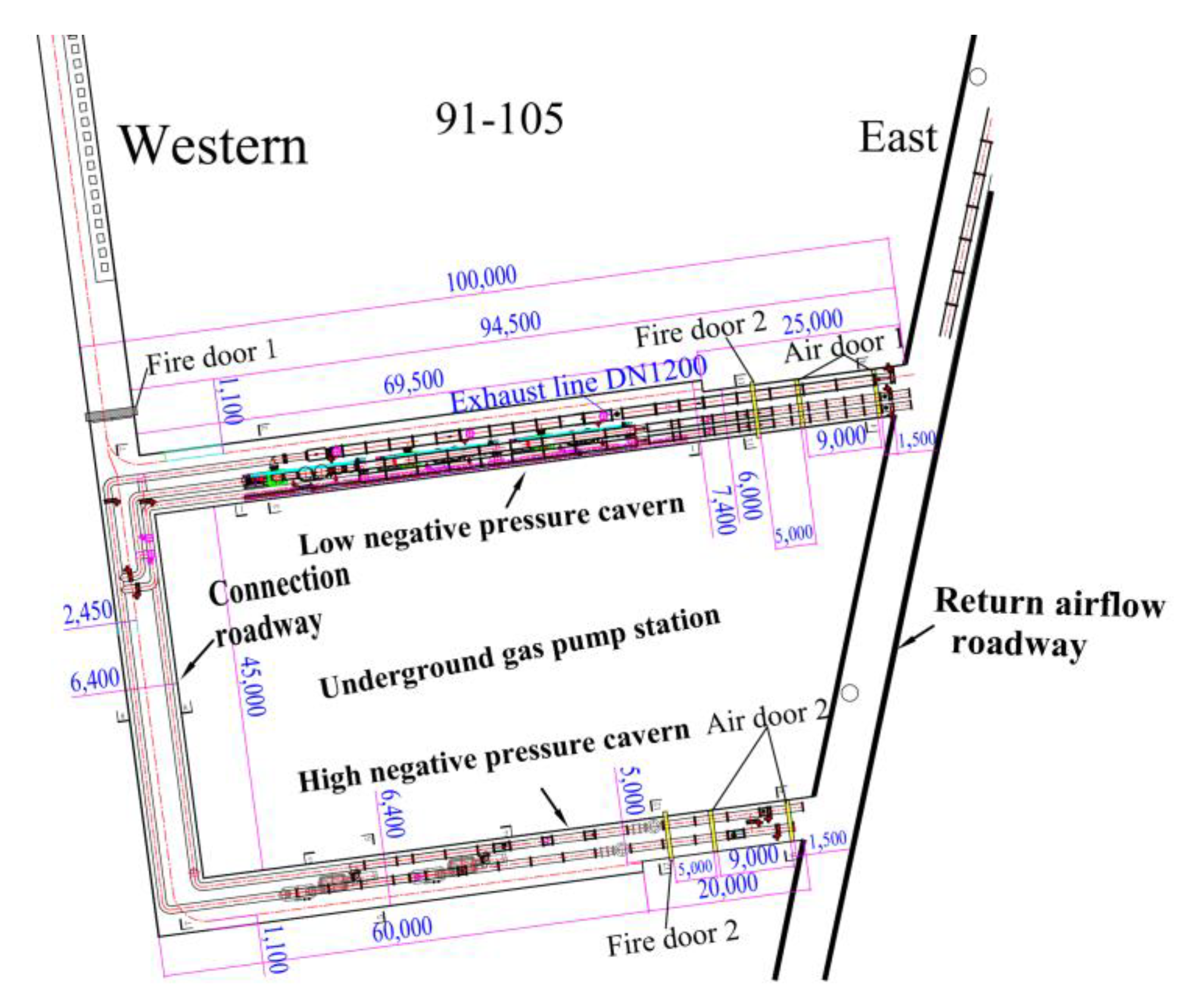
The gas pump station is located in the No. 91 mining area, which belongs to the whole coal cavern, including high- and low-negative pressure caverns. The relative positions of the two caverns are shown in Figure 1. A large gas extraction pump and pipeline need to be installed in the underground gas pumping station, which requires a large cavern size. The cavern area reached 50 m2, and its support difficulty greatly increased. The section of the connection roadway is a rectangular section with a size of 6.4 × 6.15 m2. The high-negative-pressure cavern is a rectangular chamber divided into two sections. The length of the roadway in the western section is 69.5 m, and the section size is 6.0 × 6.15 m2. The eastern section of the cavern (small section roadway) is 25 m in length and 5.0 × 4.55 m2 in size. The low-negative pressure cavern is a rectangular chamber divided into two sections. The length of the roadway in the western section is 60 m, and the section size is 7.4 × 6.75 m2. The eastern section of the cavern (small section roadway) is 20 m in length and 6.0 × 4.55 m2 in size. According to the exposure of surrounding rock in the cavern, the lithologic characteristics of the roof and floor of the cavern are shown in Table 1.
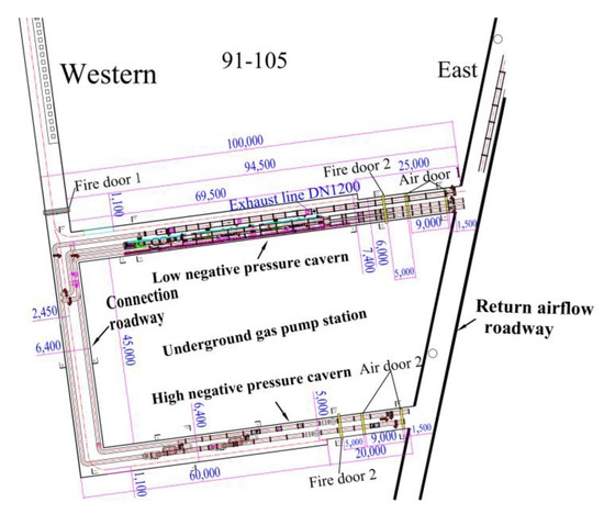
Figure 1.
The relative positions of cavern groups.

Table 1.
The lithologic characteristics of the roof and floor.
3. Method and Material
3.1. Solve the Loose Circle of the Rectangular Roadway Based on the Equivalent Circular Method
Due to roadway excavation, surrounding rock stress will be redistributed. The original stress state is destroyed, and the stress is transferred to the depth. Failure occurs when the stress reaches or exceeds the strength of the surrounding rock. It is prone to roof collapses and slough accidents. Especially in the excavation of large section whole coal cavern group, each cavern group and intersection influence each other during excavation. Stress superposition leads to a high local stress concentration coefficient in large section caverns, which is more prone to deformation and failure.
The methods to solve the loose zone of a rectangular roadway mainly include the equivalent circle method, the complex function method, and the pressure arch method. In order to quantitatively solve the plastic range of the surrounding rock during excavation of a rectangular cavern, the equivalent circle method is adopted to theoretically calculate the influence range of the surrounding rock’s loose circle caused by the excavation of a large section cavern [38]. Based on the loose circle of the circular roadway, the loose circle of the rectangular roadway is determined, and the plastic zone range of the rectangular roadway is finally determined:
- (1)
- Construction of the mechanical model of the equivalent circle method expression
In order to calculate the stress state of the roadway, the circular roadway is taken as the theoretical analysis object, and the vertical stress is set as σv and the horizontal stress as σh. We can obtain:
where λ is the lateral pressure coefficient of the rock mass;
- (2)
- Calculate the stress in the loose zone of the roadway surrounding the rock
For a circular roadway, the radial stress at any point is
The circumferential stress at any point is
The shear stress at any point is
where m = r02/r12
- r0 is the radius of the circular roadway, m;
- r1 is the radius of the loose ring, m;
- θ is the polar angle of any point in the plastic zone of the surrounding rock, °;
- (3)
- Determine the expression based on the equivalent circle method
The surrounding rock conforms to the Mohr–Coulom (M–C) constitutive by analyzing the physical and mechanical strength parameters of the surrounding rock. When the Mohr–Coulomb criterion is used to calculate the loosening range of the surrounding rock, its plastic condition is:
where Cm and φm are the cohesion and internal friction angles of the surrounding rock mass, respectively. σθ and τr are the circumferential stress and radial shear stress, respectively.
By substituting Equations (2–4) into Equation (5), we can obtain:
where
- .
When θ is given, the relationship between the radius of the plastic loosening circle and the coefficient of lateral pressure of the roadway surrounding the rock can be obtained by Equation (6). Then the radius of the loose circle in the surrounding rock is calculated to provide the theoretical conditions for roadway support. When λ = 1 and σh = σv, we can substitute into Equation (6):
Additionally the radius of the loosening ring can be obtained by Equation (7).
where r0 is the radius of the circular roadway.
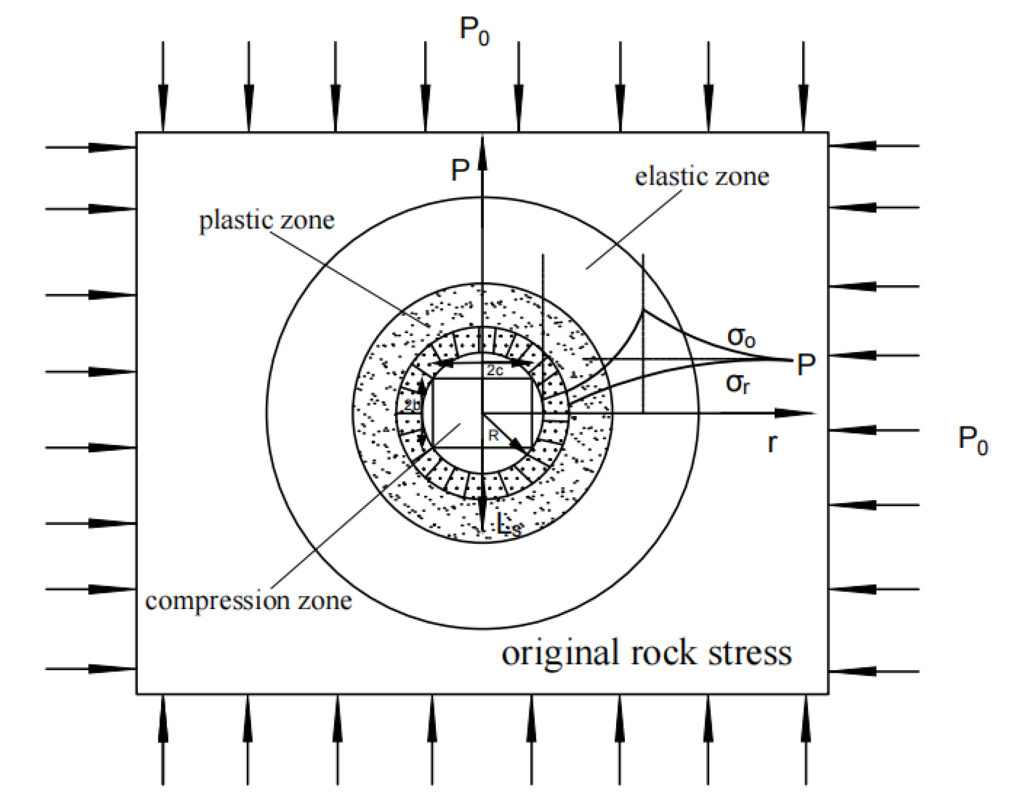
The stress change of the circular roadway can be obtained, as shown in Figure 2.
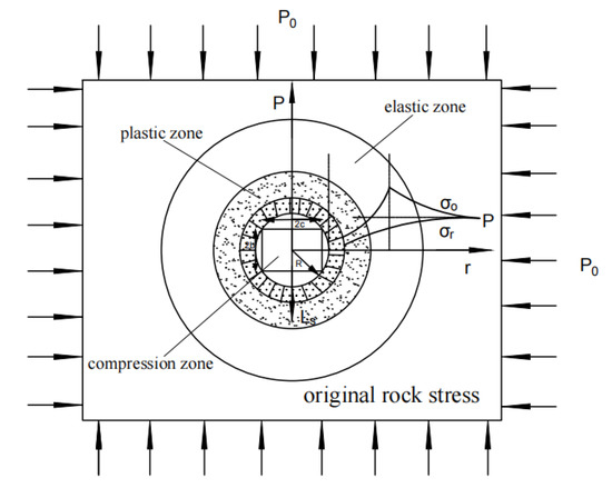
Figure 2.
Stress distribution of the circular roadway.
At the interface of the elastic zone and the plastic zone, tangential stress σθ reaches its maximum value, and the stress at the interface gradually diffuses to the depth of the roadway (see Figure 1). When the elastic zone is exceeded, the surrounding rock stress gradually returns to its initial stress state.
According to the plastic zone of the circular roadway, the plastic zone range of rectangular roadway after excavation is also solved. Assuming that the width and height of the rectangular roadway are 2c and 2d, the radius of the circular roadway is solved,
The equivalent circular radius is substituted into r0 to solve the radius range of the loose circle of the roof and two sides of the rectangular roadway. It provides the reliability basis for the design of roadway supporting parameters.
Therefore, the range of the loose circle is on the roof of the rectangular roadway:
The range of loose rings on both sides:
where d is half the height of the rectangular roadway, and c is half the width of the rectangular roadway.
Taking the cavern of the gas pump station as a case, the mechanical parameters of the roadway are r0 = 4.84 m, φm = 30°, Cm = 1 MPa, and σv = p0 = 10 MPa. By substituting into Equation (8), we obtain, r1 = 6.34 m.
By substituting r1 into Equations (9) and (10), we get the height of the roof loose ring, ls = 3.34 m, and the loose ring of the two sides, le = 2.54 m. The range of loose circles provides a theoretical basis for future roadway support technology.
3.2. Numerical Calculation
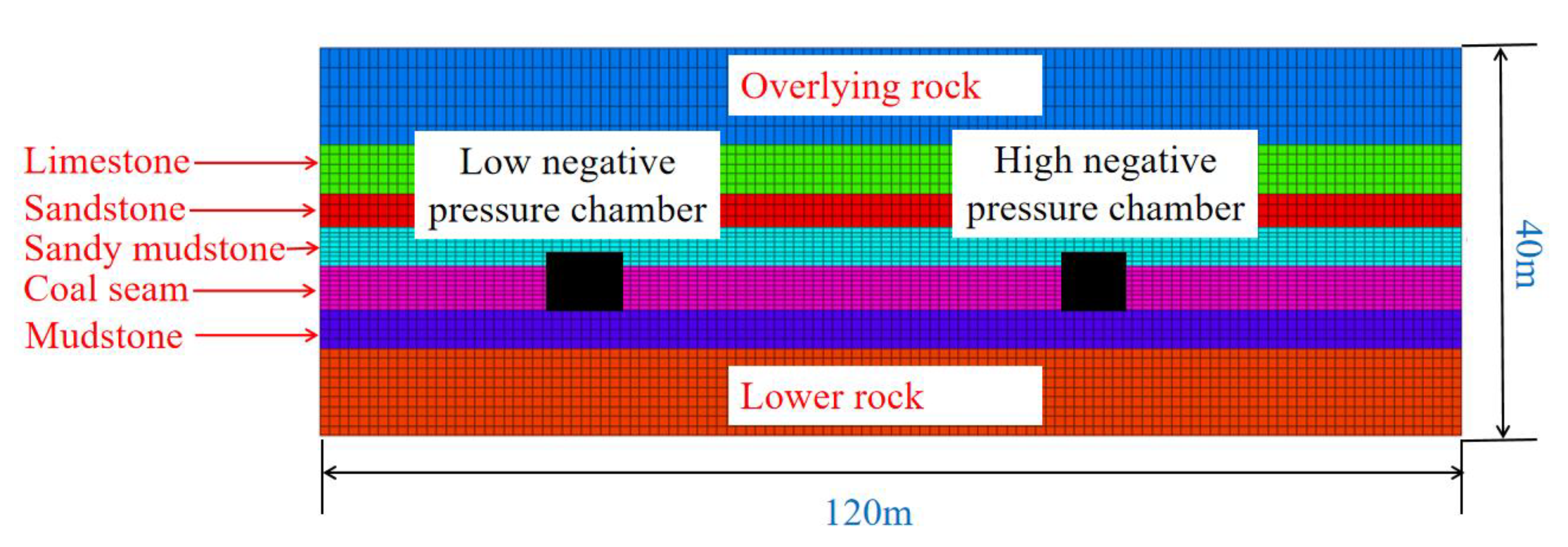
According to the geological conditions, the direction of extension of the large destressing hole was in the x-axis (120 m), the axial direction of the cavern was in the y-axis (50 m), and the vertical direction of the coal and rock mass was in the z-axis (40 m), forming a numerical calculation model as shown in Figure 3. The M-C constitutive model was used in the calculation. The boundary conditions of the model are as follows: the upper boundary is free; the horizontal displacement of the boundary around the model is constrained; and the bottom boundary is fixed. By excavating the model, the influence law of stress distribution and plastic zone distribution of the surrounding rock is simulated. The mechanical parameters of rock strata are shown in Table 2.
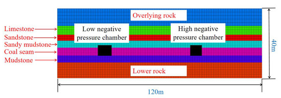
Figure 3.
Numerical model diagram.
Table 2.
Physical and mechanical properties of each stratum.
The cavern of the gas pump station studied in this paper includes a low- and high-negative pressure cavern. The numerical calculation model systematically studied the deformation and failure laws of the surrounding rock for the whole coal cavern group. The high- and low-pressure caverns are simulated according to the excavation sequence of the practical project. The excavation process is divided into five stages: the first stage is to excavate the connection roadway; the second stage is to excavate the western section of the high-negative pressure system cavern, and the length is 69.5 m; the third stage is to excavate the east section of the western section, and the length is 25 m; the fourth stage is to excavate the western section of the low-negative pressure system cavern, and the length is 60 m; and the fifth stage is to excavate the east section of the low-negative pressure system chamber, and the length is 20 m. It provides guidance for determining the supporting parameters of the whole coal cavern group.
4. Results and Discussion
4.1. Deformation Law of Surrounding Rock with Different Lateral Pressure Coefficients
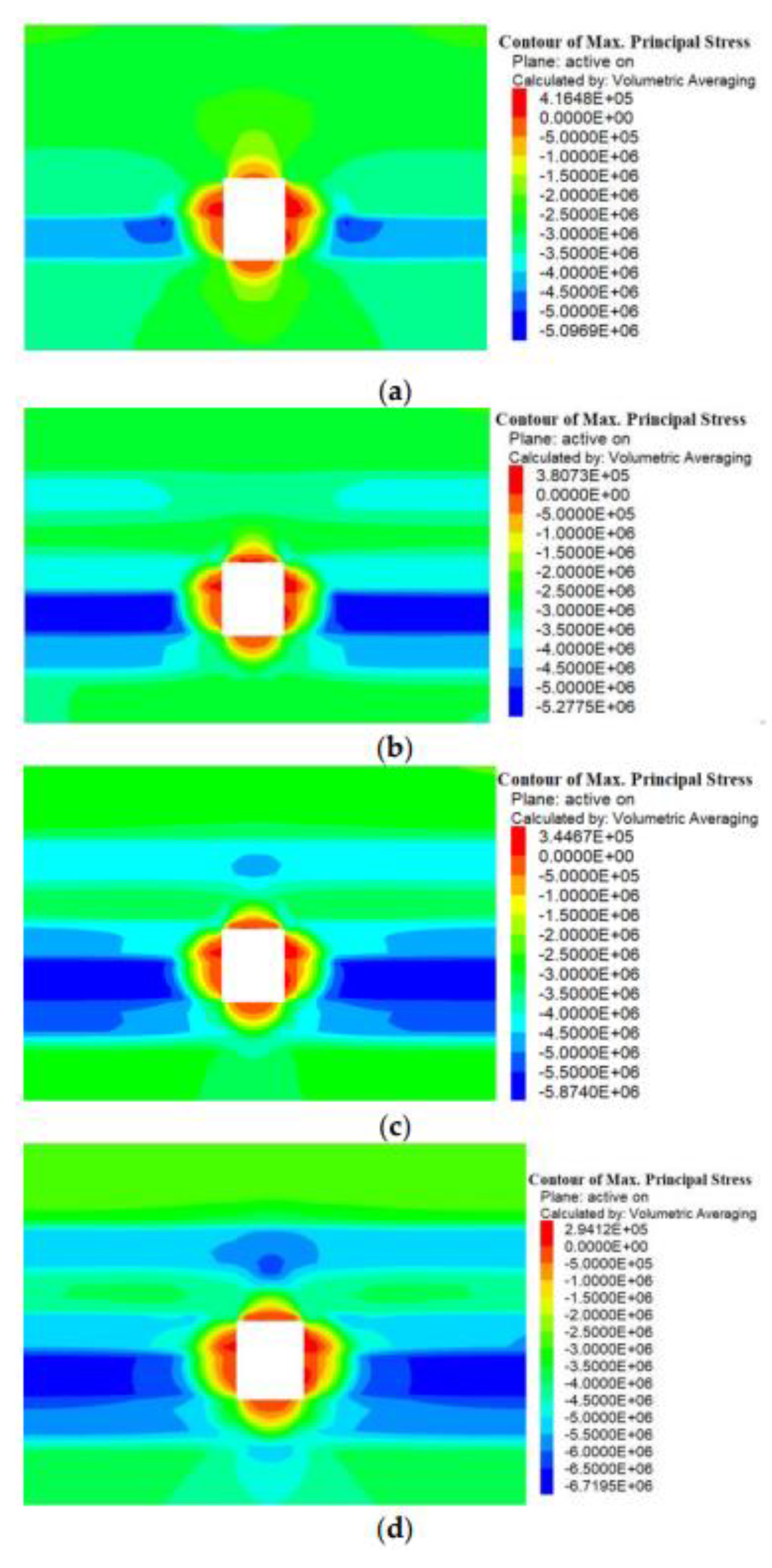
The horizontal tectonic stress in the stratum has a great influence on the stability of the surrounding rock after excavation of the cavern. In this study, a low-negative pressure cavern was selected as the research object, and the influence of different lateral pressure coefficients (γ = 0.5, 1, 1.5, and 2) on the stability of the surrounding rock in the cavern was analyzed. The nephogram of maximum principal stress and the figure of the plastic zone were shown in Figure 4 and Figure 5.

Figure 4.
A cloud diagram of the maximum principal stress with different lateral pressure coefficients. (a) γ = 0.5; (b) γ = 1.0; (c) γ = 1.5; and (d) γ = 2.0.

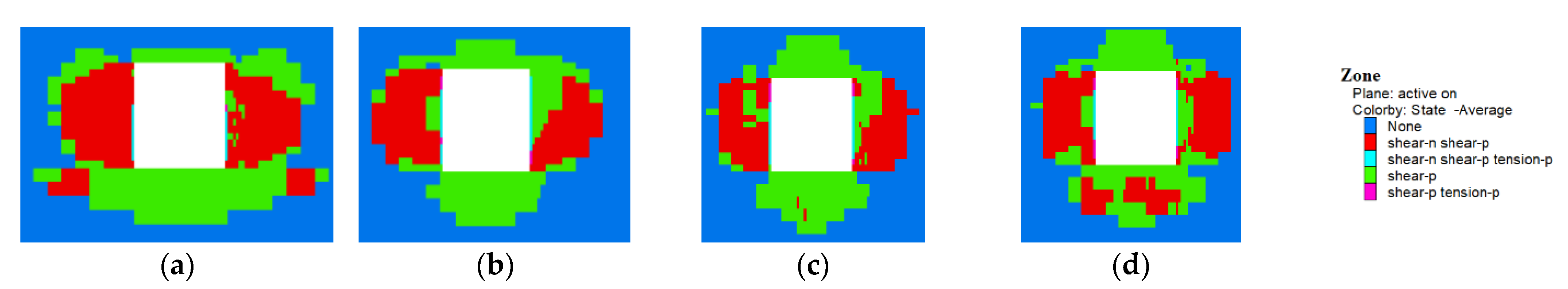
Figure 5.
A cloud diagram of the plastic zone of the cavern with different lateral pressure coefficients. (a) γ = 0.5; (b) γ = 1.0; (c) γ = 1.5; and (d) γ = 2.0.
The peak value of the maximum principal stress in the cavern gradually increases from 5.09 MPa to 6.71 MPa as the lateral pressure coefficient γ increases (see Figure 4 and Figure 5). The stress concentration area on both sides of the cavern increases laterally and then changes to longitudinal diffusion. When the lateral pressure coefficient γ = 2.0, the stress concentration area appears in the roof. The stress distribution of the vertical stress relative to the maximum principal stress changes little with the lateral pressure coefficient. The area of stress concentration near the cavern gradually increases, but the peak value of vertical stress gradually decreases. With the increasing lateral pressure coefficient, the plastic zone area of the cavern decreases. Additionally, under the influence of horizontal stress, the scope of the plastic zone gradually decreases in the two sides of the cavern, so as to gradually extend to the top and floor, and the distribution of the plastic zone changes from a chunky distribution to a thin distribution.
4.2. Stress Variation Characteristics for the Whole Coal Cavern Group
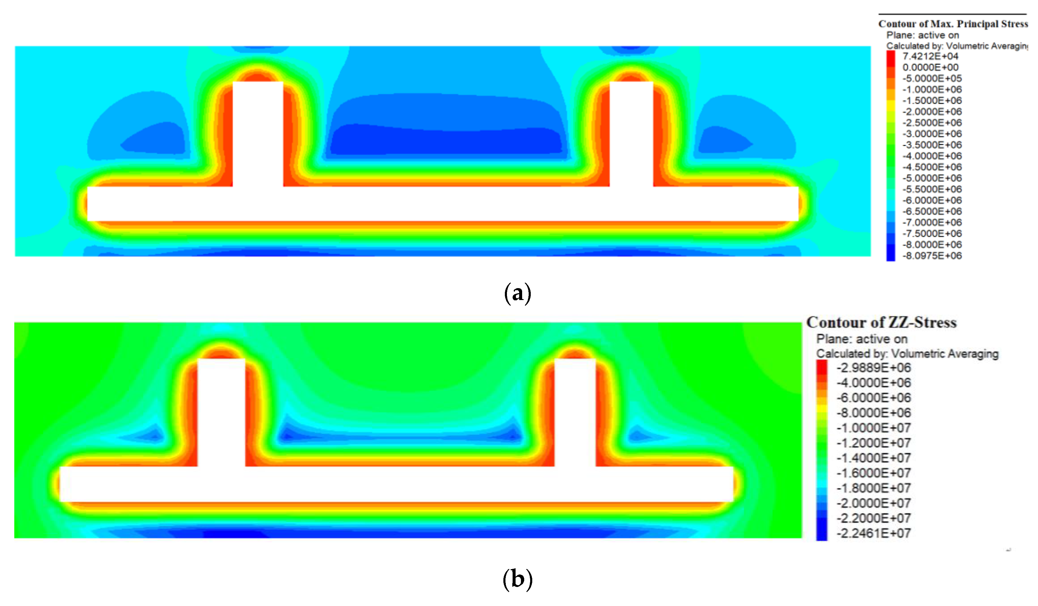
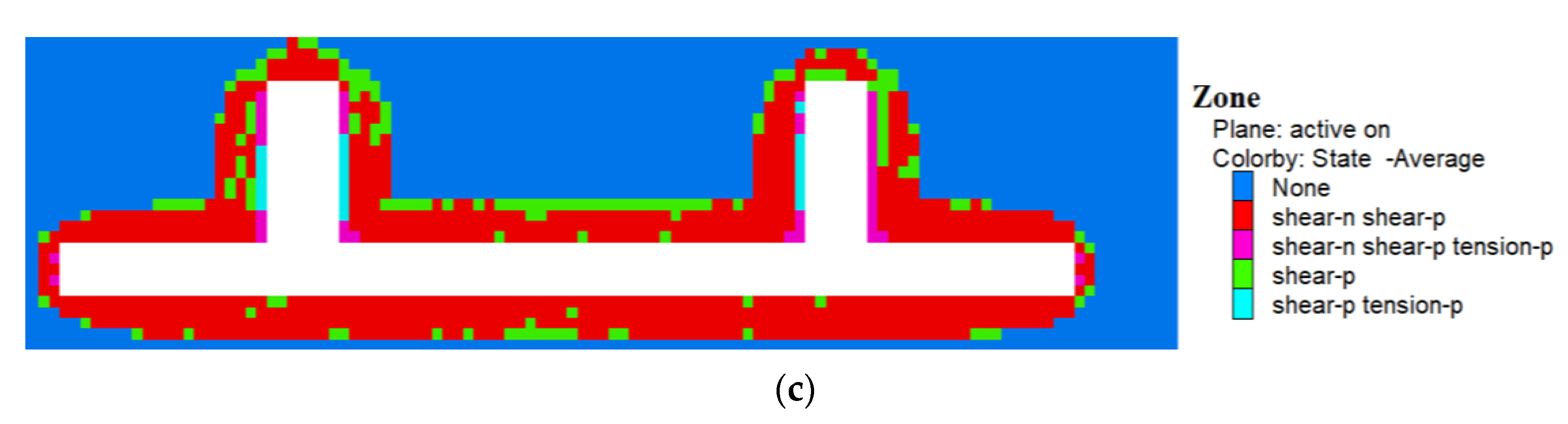
In order to analyze the distribution law of stress and plastic zone in the cavern groups with different heights, three sections were selected along the z-axis. The sections are located at h = 3 m (the middle position of the large roadway), h = 5 m (the roof position of the large roadway), and h = 8 m (the roof position of high- and low-negative pressure caverns) from the coal seam floor. The simulation results are shown in Figure 6, Figure 7 and Figure 8.
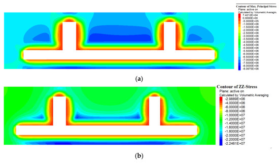
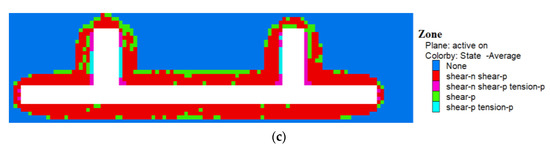
Figure 6.
Surrounding rock variation characteristics for h = 3 m. (a) Maximum principal stress distribution; (b) vertical stress distribution; and (c) plastic differential distribution.
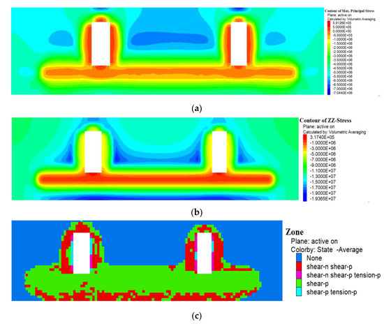
Figure 7.
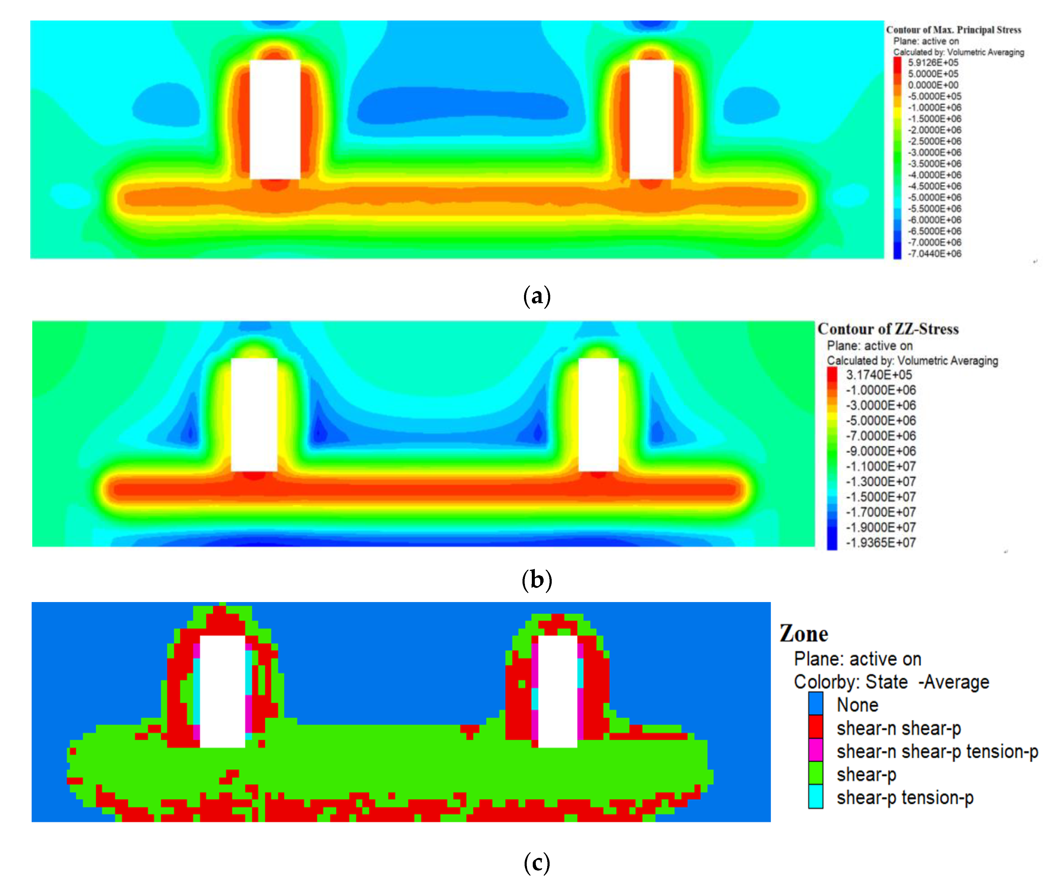
Surrounding rock variation characteristics for h = 5 m. (a) Maximum principal stress distribution; (b) vertical stress distribution; and (c) plastic differential distribution.
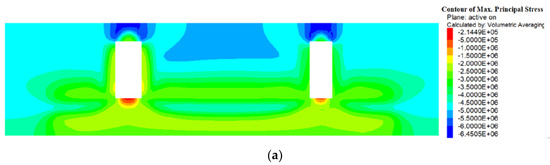
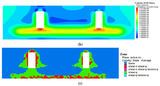
Figure 8.
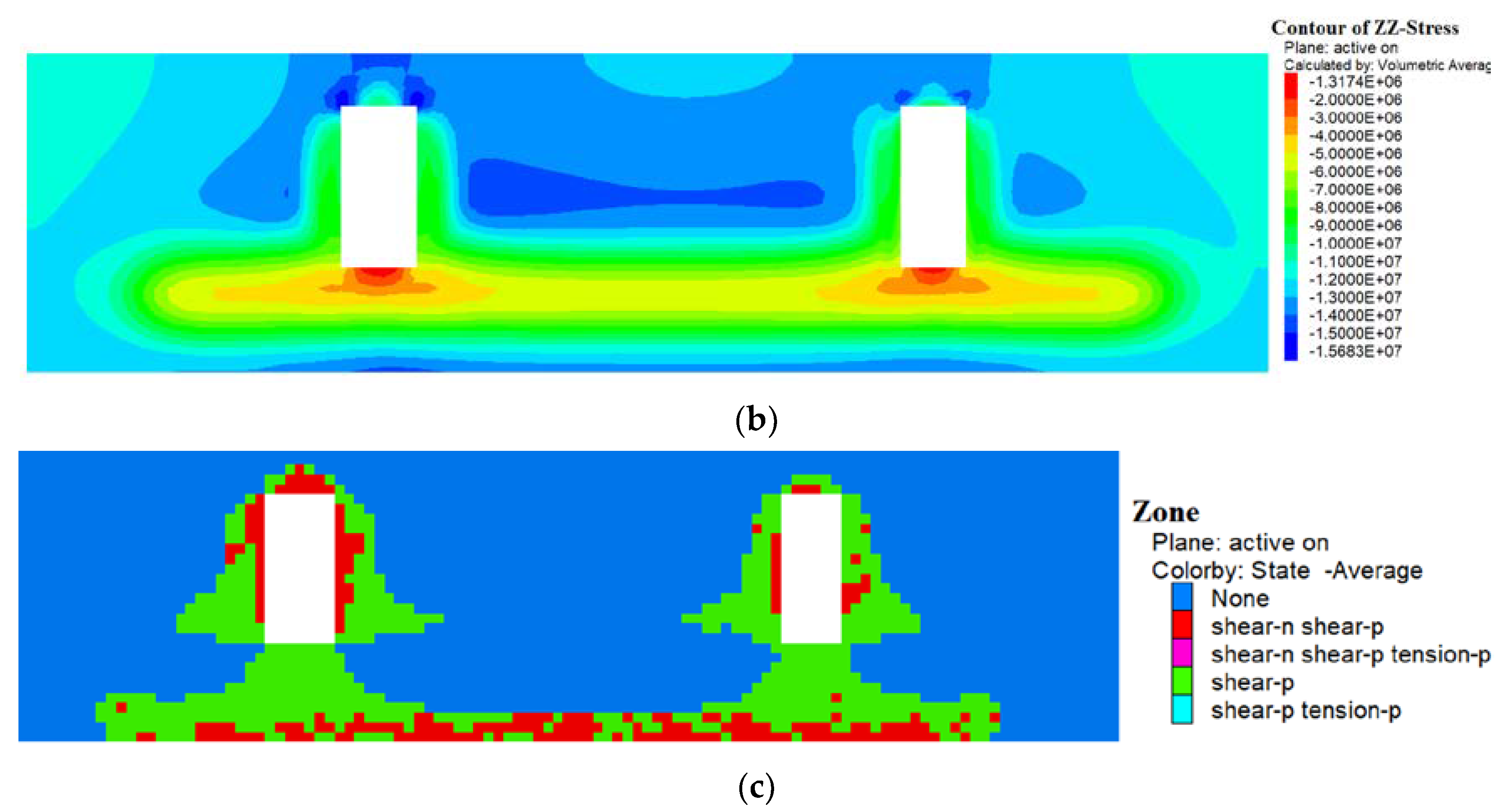
Surrounding rock variation characteristics for h = 8 m. (a) Maximum principal stress distribution; (b) vertical stress distribution; and (c) plastic differential distribution.
- (1)
- The simulation result at h = 3 m
The height of the roadway near the underground pumping station is 3.5 m, and the surrounding rock variation in the position 3 m away from the coal seam floor is shown in Figure 6.
The distribution range of tensile stress generated by the excavation of the cavern is larger than that of the roadway (see Figure 6a). The maximum principal stress is larger in the area between the cavern groups, and the highest value is 8.09 MPa. The distribution law of vertical stress is roughly similar, but the maximum vertical stress value is 22 MPa (see Figure 6b). The larger the section of the cavern, the larger the scope of the plastic zone. The failure mode of the surrounding rock is mainly shear failure (see Figure 6c);
- (2)
- The simulation result at h = 5 m
The surrounding rock variation in a position 5 m away from the coal seam floor is shown in Figure 7.
The peak values of the maximum principal stress and vertical stress decrease to 7.04 MPa and 19.3 MPa, respectively (see Figure 7a,b). The roof position of the roadway is obviously in the tensile stress zone, and the stress concentration area of the vertical stress begins to increase. The larger the section of the cavern, the greater the range of stress concentration. The larger the section of the cavern is, the larger the scope of the plastic zone is. The tensile failure occurs on the two sides of the cavern, the shear failure occurs in the rest of the scope, and the overall scope of the plastic zone increases gradually;
- (3)
- The simulation result at h = 8 m
The surrounding rock variation in a position 8 m away from the coal seam floor, is shown in Figure 8.
The peak values of the maximum principal stress and vertical stress decrease to 6.45 MPa and 15.6 MPa, respectively (see Figure 8a,b). In this section, the stress near the cavern is not affected by the main roadway. The larger the section of the cavern, the greater the stress on the surrounding rock, and obvious stress asymmetry occurs. The plastic zone of the cavern continues to expand to the two sides as it moves away from the floor. The larger the section of the cavern, the larger the scope of the plastic zone. The range and distribution of the plastic zone obtained by numerical simulation are consistent with the theoretical results. These results can provide theoretical support for determining the supporting parameters, such as the length of the bolts and the cables;
- (4)
- Stress distribution characteristics of cavern groups at different heights
Three sections were selected along the z-axis: the bottom of the cavern, the middle of the cavern, and the roof of the cavern. The stress curves for different heights were obtained, as shown in Figure 9.
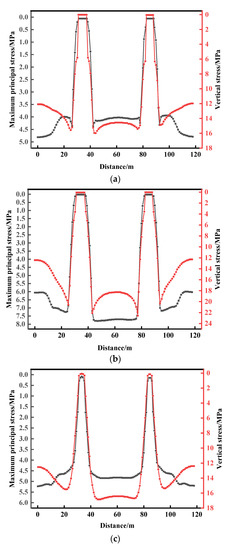
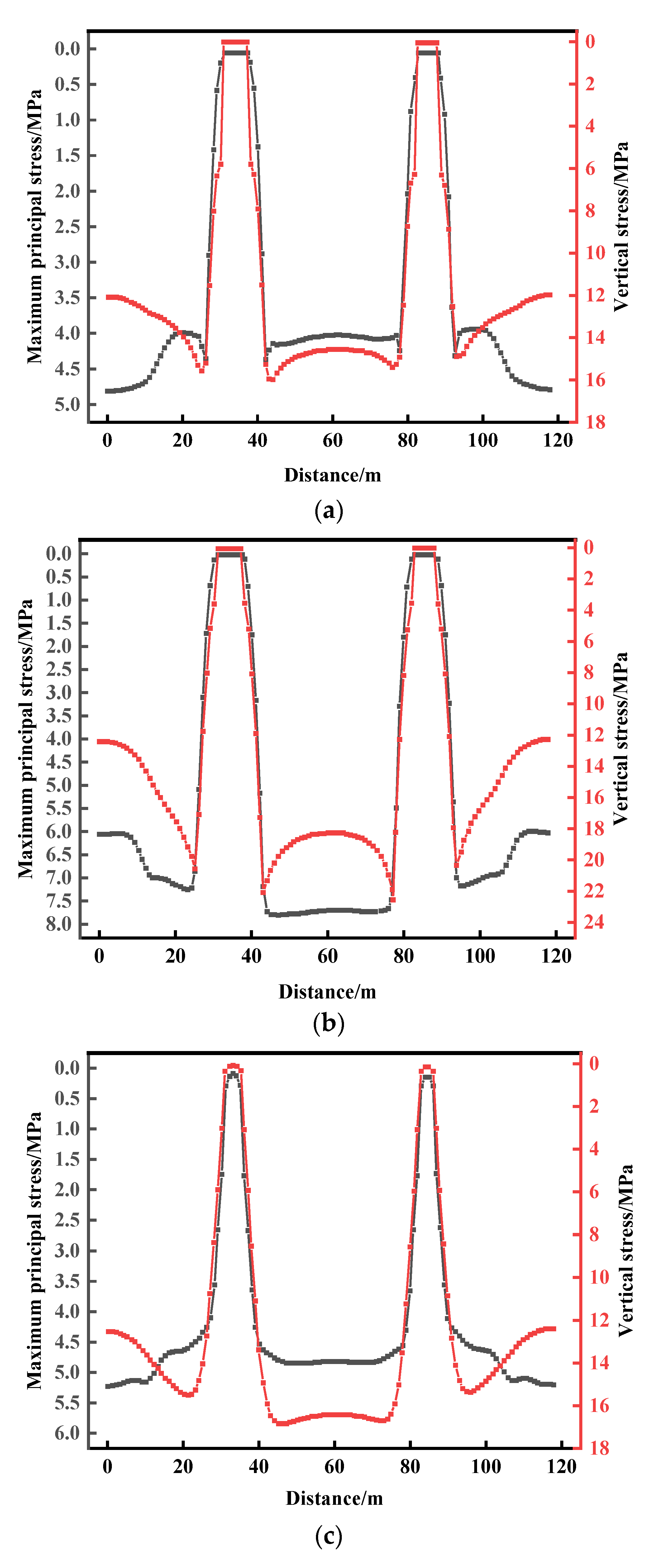
Figure 9.
Stress variation characteristics of different section heights in the cavern group. (a) The roof position of the cavern; (b) the middle position of the cavern; and (c) the bottom position of the cavern.
The maximum principal stress of the roof attenuates sharply near the cavern and shows obvious stress concentration on the two sides of the cavern (see Figure 9). The variation trend of vertical stress is consistent with that of maximum principal stress. At the boundary of the model, the maximum principal stress and vertical stress increase and decrease sharply. In addition, the larger the section of the cavern, the greater the stress peak. In the middle of the cavern, the stress peak of the surrounding rock increases as a whole, and the distribution of the maximum principal stress is relatively stable among the cavern groups while the vertical stress increases gradually from high to low. Compared with the middle part of the cavern, the stress peak of surrounding rock near the bottom of the cavern gradually decreases, and the maximum and minimum principal stresses between the cavern groups show uniform distribution, but the influence range gradually decreases.
4.3. Displacement Characteristics of the Whole Coal Cavern Group
The displacement cloud chart of the cavern group obtained by the numerical simulation is shown in Figure 10.
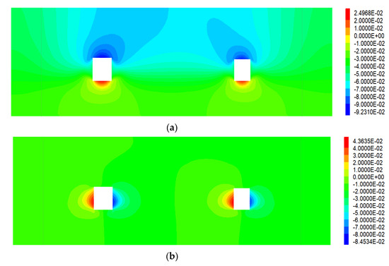
Figure 10.
A cavern displacement cloud chart. (a) The vertical displacement cloud chart; and (b) the horizontal displacement cloud chart.
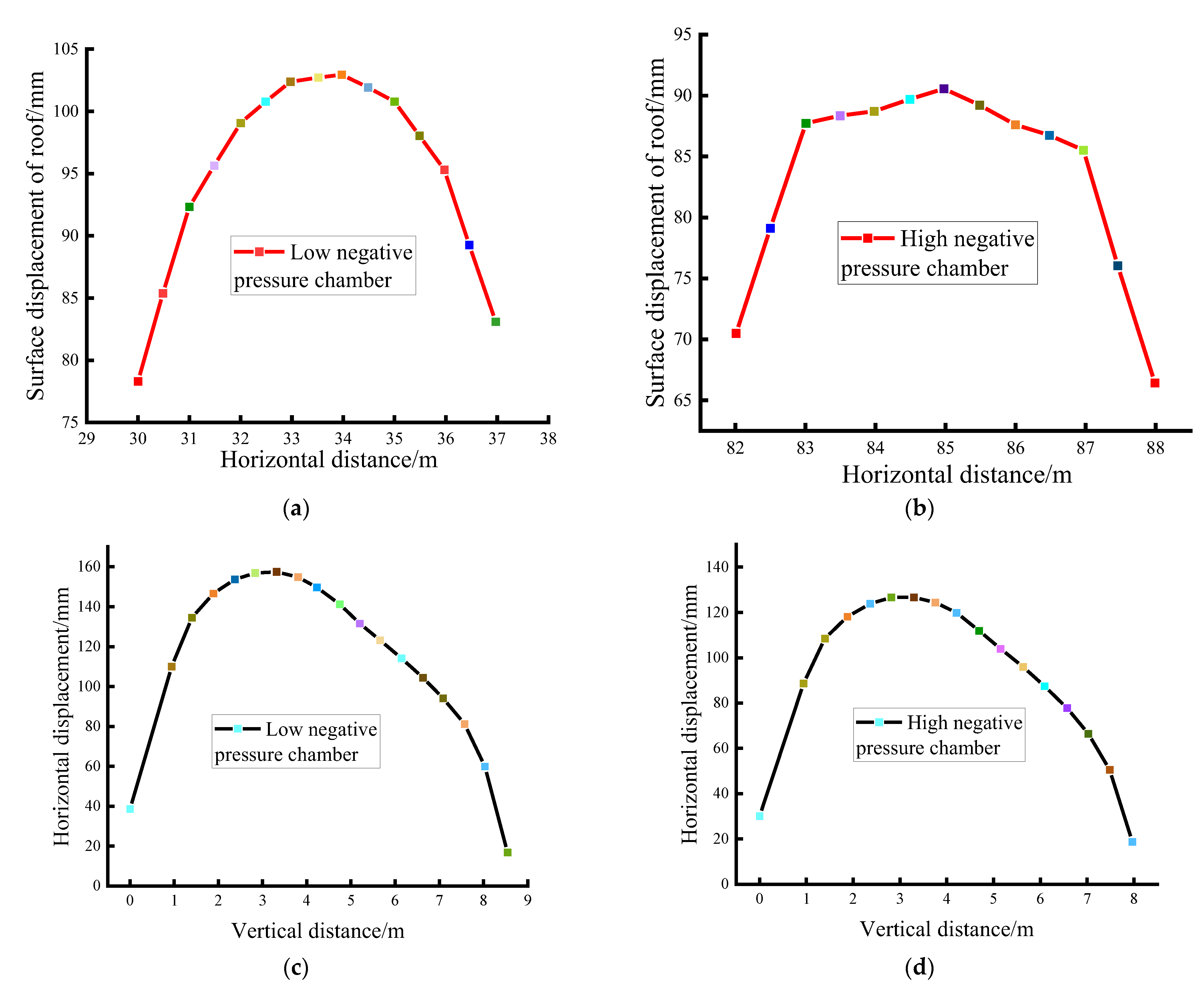
The larger the section of the cavern, the greater the displacement of the roof caused by the excavation of the cavern. The maximum displacements of low- and high-negative pressure caverns are 103.2 mm and 92.4 mm, respectively (see Figure 11). The maximum two-sided displacement is 160 mm and 125 mm, respectively. The roof displacement curve of the low-negative pressure cavern is asymmetrical. The roof displacement of the high-negative pressure cavern has a saddle-shaped distribution and reached a maximum in the cavern roof left and right, respectively. The two sides of the cavern have an asymmetrical arch distribution. It indicates that a two-sided displacement in the middle and upper parts of the cavern is larger.
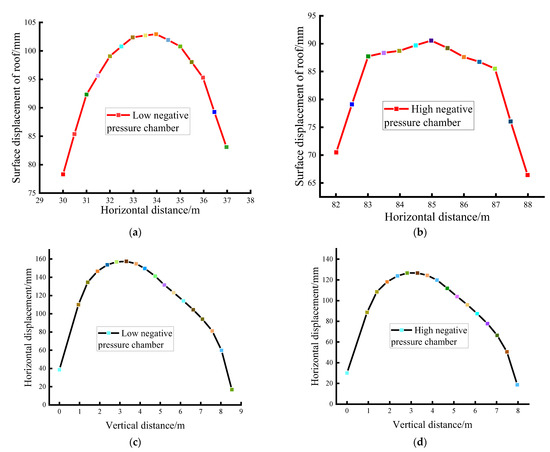
Figure 11.
A cavern displacement diagram. (a) Roof displacement of a low-negative pressure cavern; (b) roof displacement of a high-negative pressure cavern; (c) two-sided displacement of a low-negative pressure cavern; and (d) two-sided displacement of a high-negative pressure cavern.
4.4. Control Technology and Application for Large Section Whole Coal Cavern Groups
4.4.1. A Novel Stratified Reinforcement Ring Concept of the LBG
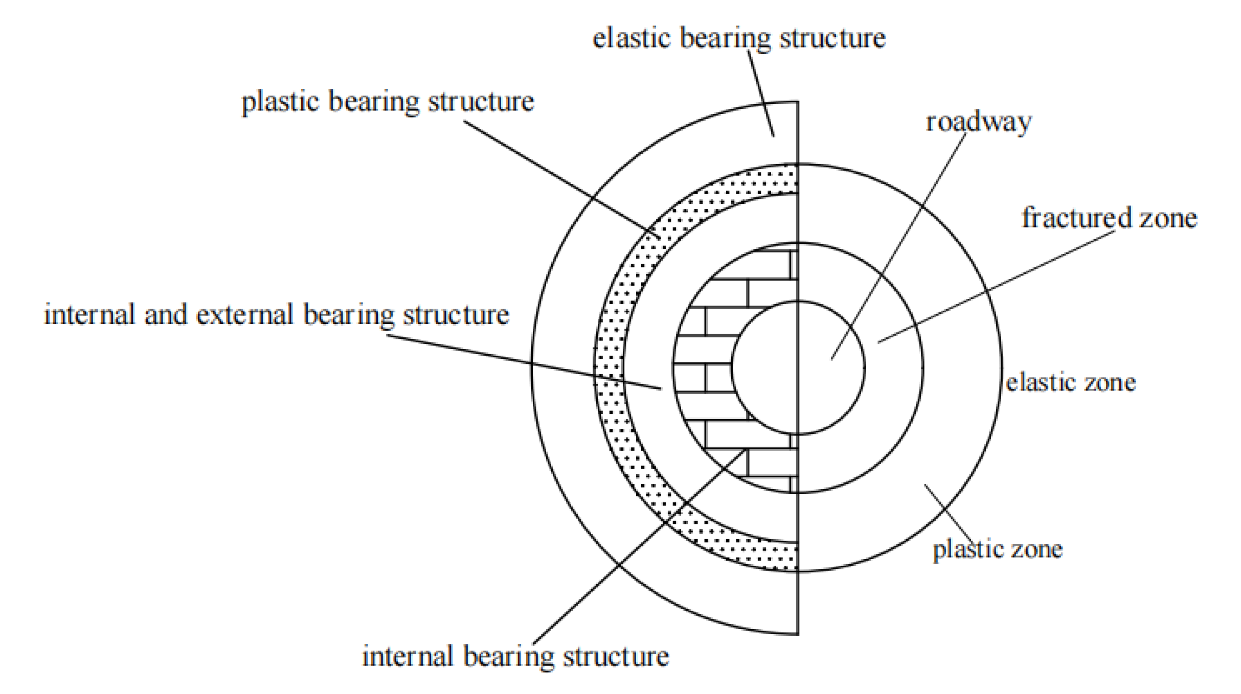
According to the stress distribution nephogram and curve of the cavern group, the surrounding rock of the roadway can be divided into internal and external bearing structures, as shown in Figure 12.
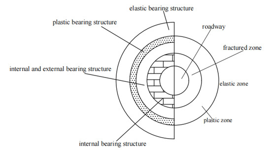
Figure 12.
A schematic diagram of the inner and outer bearing structures of the surrounding rock.
Different stress states in the broken zone, plastic zone, and elastic zone require different supporting strengths. The supporting effect should be coupled with the mechanical characteristics of the surrounding rock to effectively control the deformation and failure of the surrounding rock. A novel stratified reinforcement ring concept of “long cable-bolt-grouting” (LBG) was proposed to control the deformation of a whole coal cavern group based on the obtained deformation mechanism. The specific surrounding rock control mechanism is as follows:
- (1)
- The surrounding rock of the cavern is divided into the fracture zone, the plastic zone, and the elastic zone from a shallow part to a deep part. The damage degree decreases gradually, and the support strength required to achieve stability also decreases gradually. The coordinated support of an anchor bolt, a grouting anchor cable, and a long anchor cable can meet this requirement. In the shallow part of the surrounding rock, the supporting density demand of a bolt, a grouted anchor cable, and a long anchor cable is small, while the supporting strength demand is large. In the deep surrounding rock, the support density demand decreases successively, and the support intensity decreases correspondingly. By partitioning the surrounding rock and adding reinforcement, a stable bearing circle that is consistent with the surrounding rock can be formed. For the fracture zone (0–2.5 m), plastic zone (3–8 m), and elastic zone (beyond 8 m), the coordinated support technology of an anchor bolt (3 m), a grouting anchor cable (8.3 m), and a long anchor cable (15 m) has been proposed and adopted to connect the broken zone, the plastic zone, and the elastic zone. Three kinds of supporting equipment are arranged at intervals and form three stable bearing rings of 0–3 m, 3–8 m, and 8–15 m from the shallow to deep layer of the surrounding rock;
- (2)
- By using a high-strength and high-preload anchor cable support, the supporting function of an anchor bolt cable and the bearing capacity of surrounding rock can be fully demonstrated. In the early stages of excavation of a large section cavern, the surrounding rock’s deformation speed is greater. A high-prestressed anchor bolt and a cable support can not only provide greater initial support resistance but also have good resistance-increasing performance, so that the rock strata in the broken zone, the plastic zone, and the elastic zone are locked as a whole. The internal friction angle and cohesion of the rock strata within the anchorage range can be improved so as to realize active and timely support and effectively limit the development of surrounding rock deformation and failure;
- (3)
- Partition grouting reinforcement can improve the mechanical properties and stability of the surrounding rock. The cable support, with its high strength and high preload, can effectively control the deformation of the surrounding rock. However, primary and new fissures in the surrounding rock will expand to a certain extent. In order to achieve long-term stability of the surrounding rock, it is still necessary to improve the strength of the rock by grouting. Partition grouting reinforcement is mainly used to reinforce the fracture zone (0–2.5 m) and the plastic zone (3–8 m), respectively. Firstly, low-pressure grouting of a shallow hole is applied to the fracture zone, and then high-pressure grouting of the deep hole is applied to the surrounding rock in the plastic area. The grouting effect can be improved effectively through the combination of deep- and shallow-hole grouting. After grouting, the anchoring effect and supporting stiffness of an anchor bolt and an anchor cable are further strengthened, and the stability of the surrounding rock is further improved.
4.4.2. Determine the Surrounding Rock Control Parameters of the Whole Coal Cavern Group
The surrounding rock control parameters of the whole coal cavern group are determined based on the deformation and failure characteristics of the whole coal cavern group and the above surrounding rock control theory. On the roof of whole coal cavern groups, the supporting configuration of a high-strength bolt with a high pre-tightening force and a high-strength anchor with a high pre-tightening force were determined. On the two sides and floor of the whole coal cavern group, the grouting was determined. These two supporting configurations, in both the roof and two sides, were applied in the large section gas storage cavern group. The specific parameters are as follows:
- (1)
- Roof support parameters of the cavern group
On the roof of whole coal cavern groups, the supporting configuration of a high-strength bolt with a high pre-tightening force and a high-strength anchor with a high pre-tightening force were determined.
In the roof and two sides of the cavern, the anchor cable specifications are Φ 22 × 9300 mm2 and Φ 22 × 8300 mm2, and the spacing and row layout are 1600 × 1600 mm2 and 1500 × 1600 mm2. The size of the bolt is Φ 22 × 2400 mm2 with high-strength ribbed steel. The size of the laying metal mesh is 100 × 100 mm2, and a WD 280-2.7 steel belt is adopted. The thickness of the concrete injection is 150 mm, and the roof is reinforced with a combined prestressed anchor cable. There are five combined anchor cables, each of which is prestressed with a dimension of 22 × 12,300 mm2 and a spacing and row spacing of 2200 × 3200 mm2. The supporting form of the roadway is shown in Figure 13;
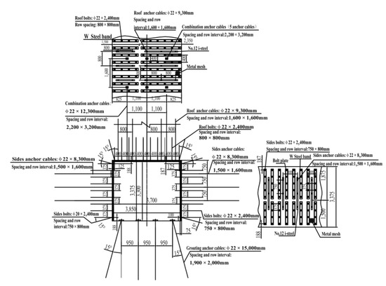
Figure 13.
The roadway support layout plan.
- (2)
- Grouting parameters
Three holes are arranged in each row of the cavern sections. The top row holes are 1.5 m away from the roof, the bottom row holes are 1.5 m away from the floor plate, and the middle holes are 3.3 m away from the floor plate. The holes are arranged in parallel. The diameter of the grouting hole is 42 mm, and the depth of the hole is 3 m. A seamless steel pipe is used as the grouting pipe. The hole sealing depth must be at least 1 m, and the hole sealing device is used to seal the hole. Shallow-hole grouting pressure is 2.0–4.0 MPa using a pneumatic single liquid grouting pump, and the diffusion radius is about 2 m.
5. Verification and Application
5.1. Numerical Simulation Results of LBG Control Technology
In order to study the control effect of the roadway surrounding rock with LBG technology and verify the rationality of the support scheme and parameters, a FLAC3D finite difference program was used to simulate the stress and deformation of the roadway surrounding rock. The stress and displacement nephograms are shown in Figure 14 and Figure 15.
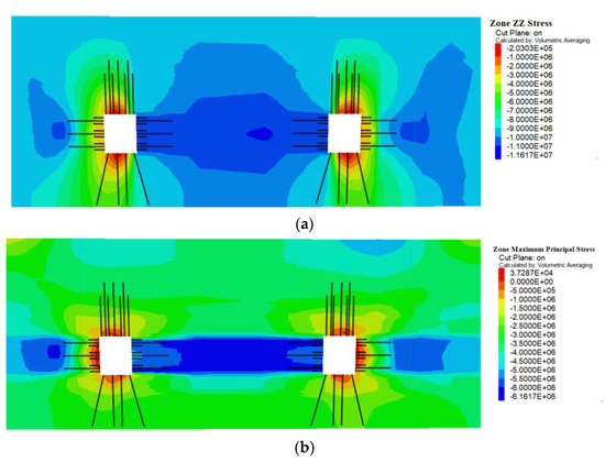
Figure 14.
A stress cloud chart of LBG control technology. (a) A vertical stress cloud chart of LBG control technology; and (b) a maximum principal stress cloud chart of LBG control technology.
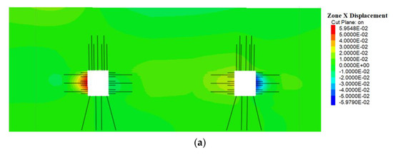
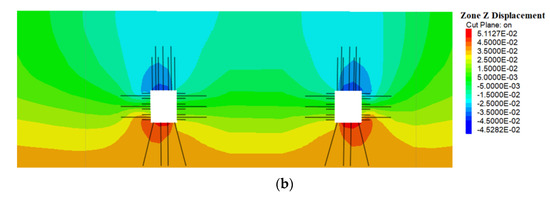
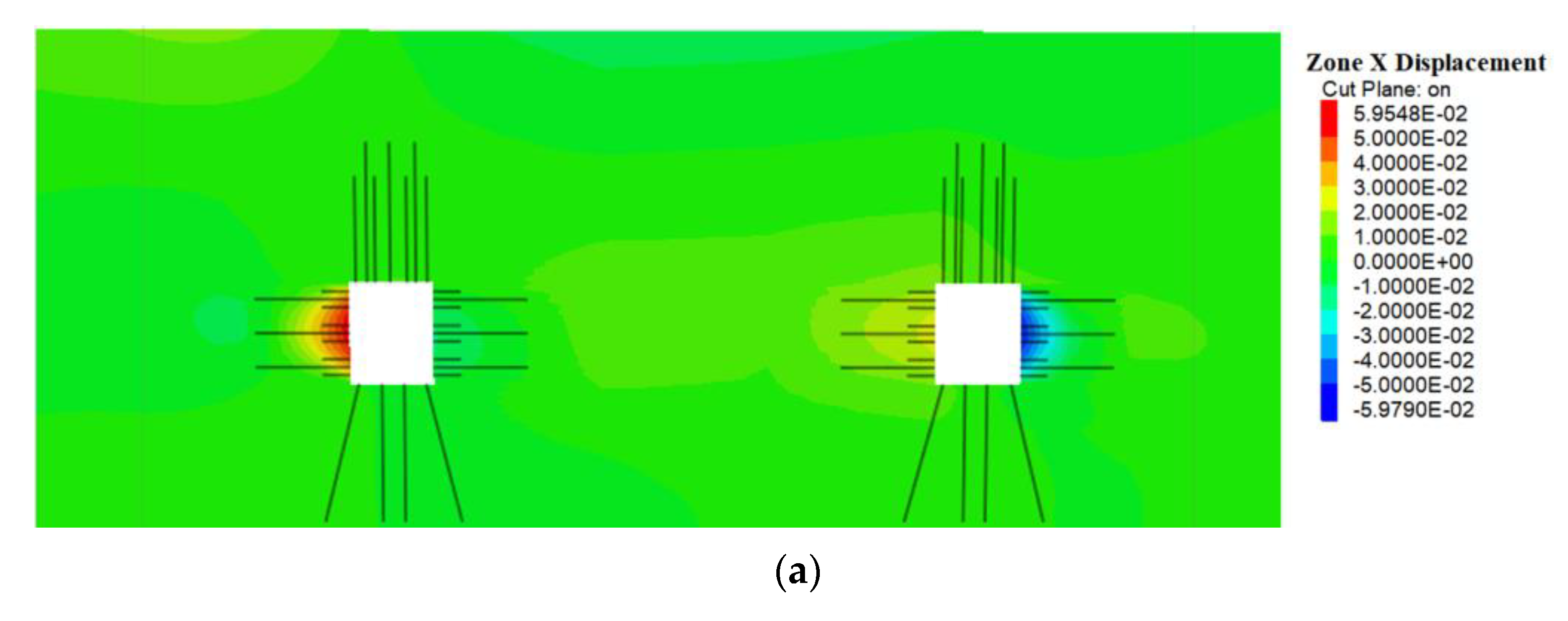
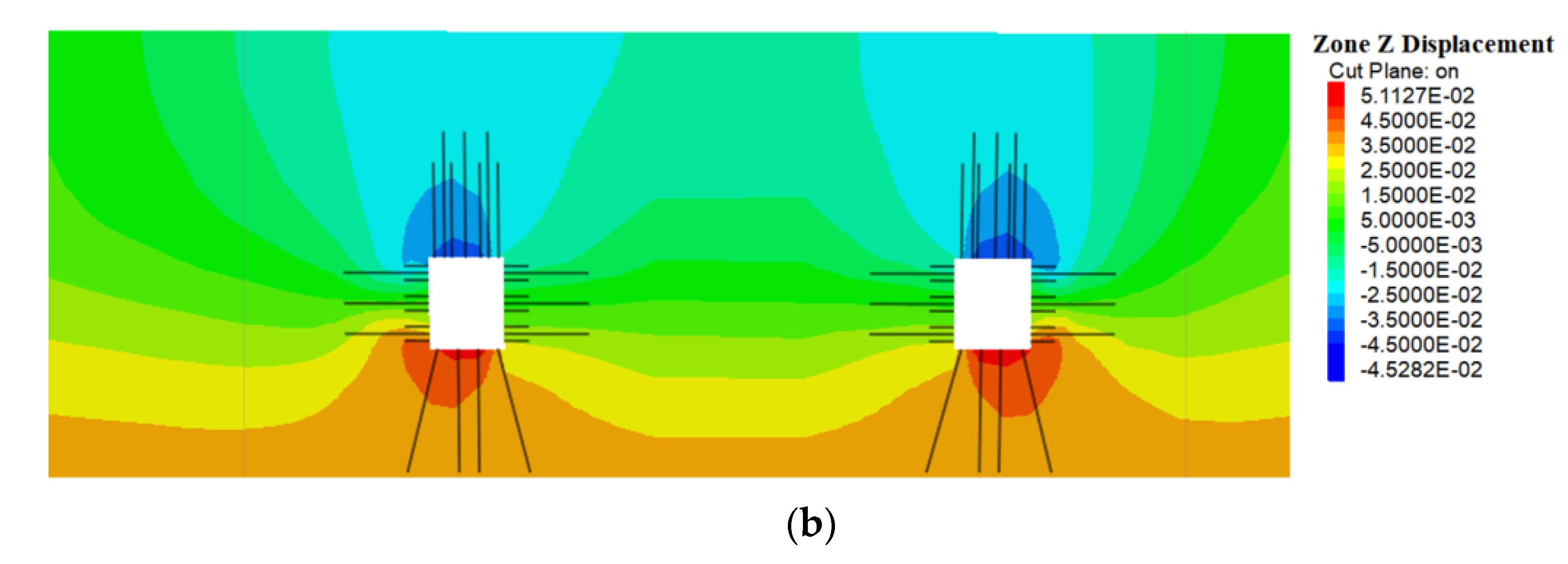
Figure 15.
Displacement cloud chart of LBG control technology. (a) A horizontal displacement cloud chart of LBG control technology; and (b) a vertical displacement cloud chart of LBG control technology.
The stress and displacement nephograms (Figure 14 and Figure 15) show that the LBG control technique can effectively improve the stress state of the surrounding rock in the chamber groups. The tensile stress of the surrounding rock is reduced, and surrounding rock control technology plays an active supporting effect. The maximum principal stress is reduced. The two-sided displacement and roof subsidence are reduced, and roadway deformation is completely controlled within the required range, which ensures the stability of the surrounding rock. It shows that LBG control technology is reasonable.
5.2. Engineering Practice
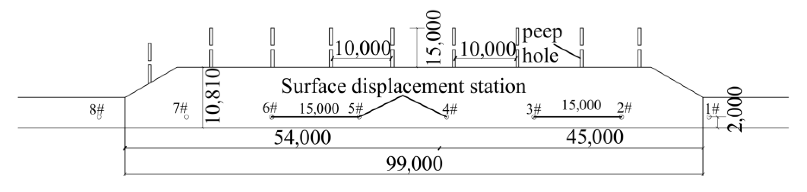
The supporting configurations in both the roof and sidewalls above were applied to the large section gas storage cavern group. In order to verify the rationality of the proposed surrounding rock control technology, a roof separation instrument and a borehole peeping instrument are arranged in the reinforcement section of the cavern to monitor the surface displacement change of the cavern. Eight measuring stations are arranged in the main body of the cavern (measuring stations 2–7) and the connecting crossover points of the cavern (measuring stations 1 and 8). The monitoring diagram and results are shown in Figure 16 and Figure 17. The field monitoring results and numerical simulation results on the maximum deformation of the surrounding rock are compared (Figure 18, Figure 19 and Figure 20).
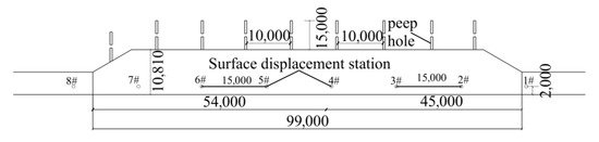
Figure 16.
Layout of surface displacement measuring points and peep holes.
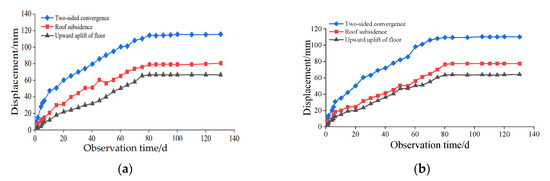
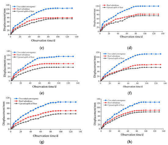
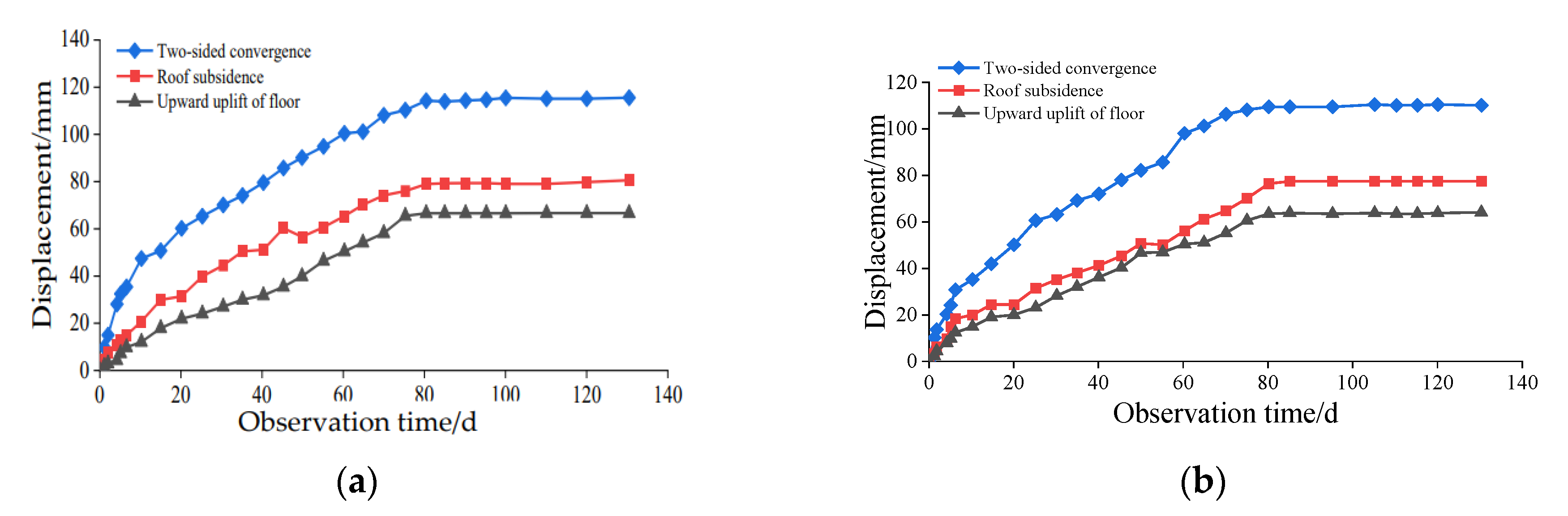
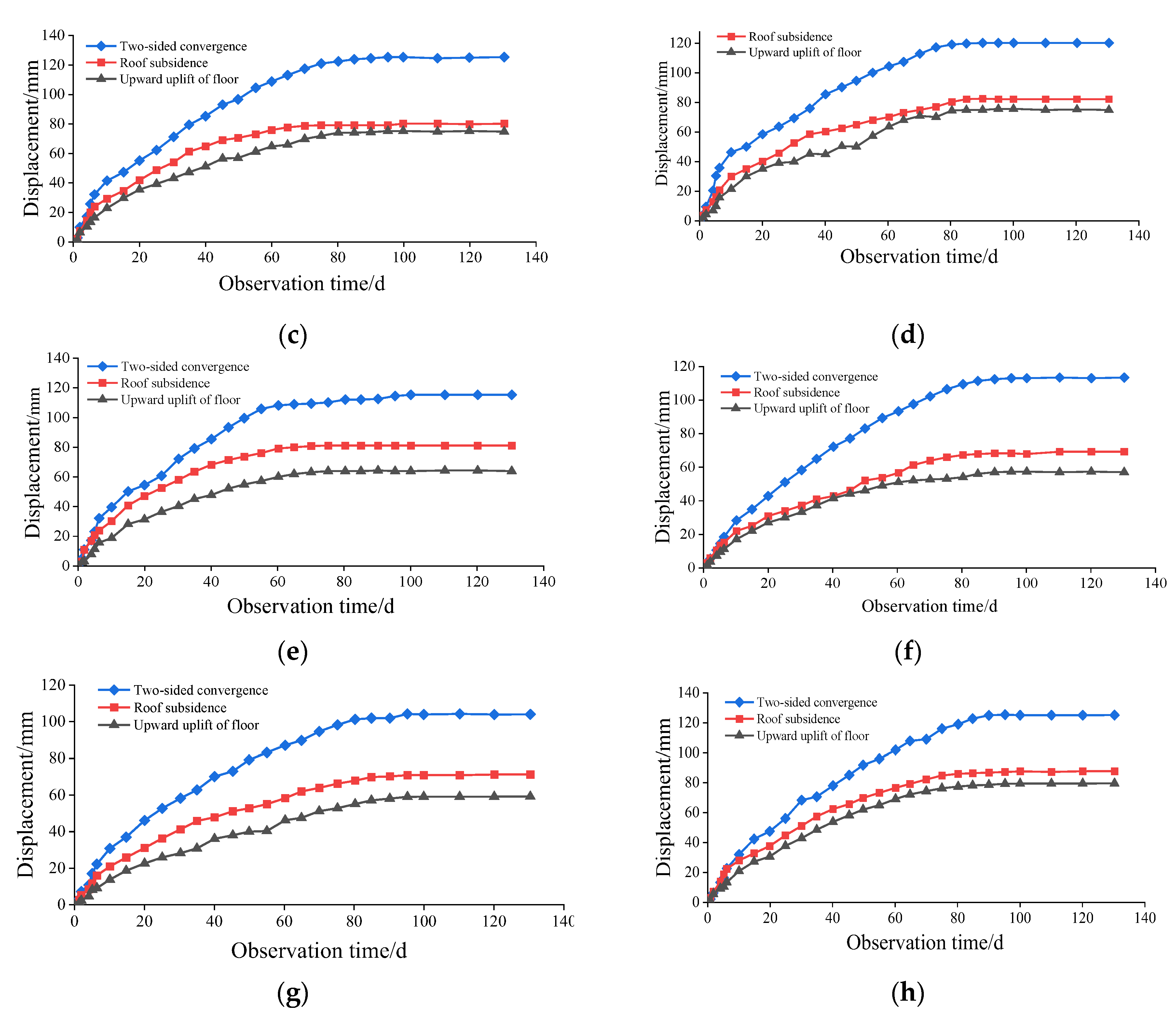
Figure 17.
Surrounding rock deformation curve. (a) 1#; (b) 2#; (c) 3#; (d) 4#; (e) 5#; (f) 6#; (g) 7#; and (h) 8#.

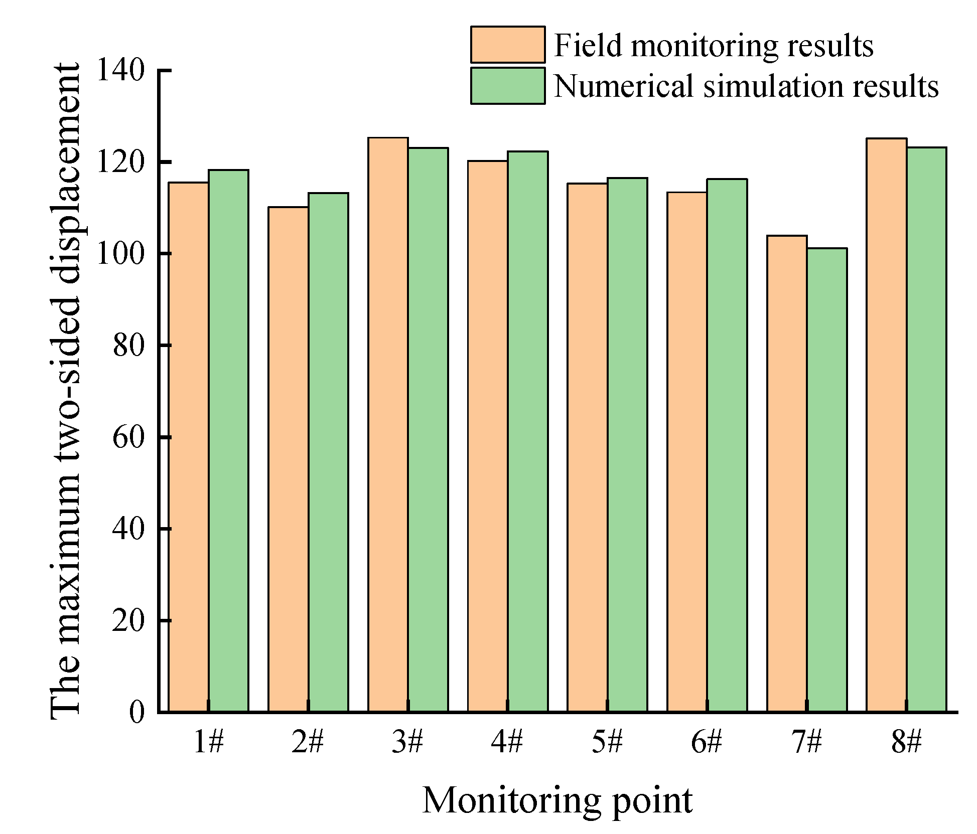
Figure 18.
Numerical simulation results versus the field monitoring results of the maximum two-sided displacement.
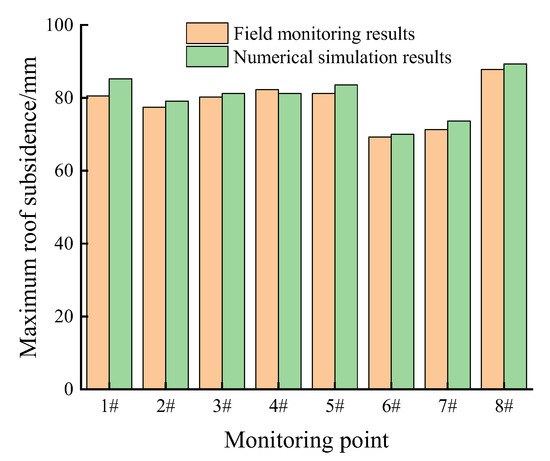
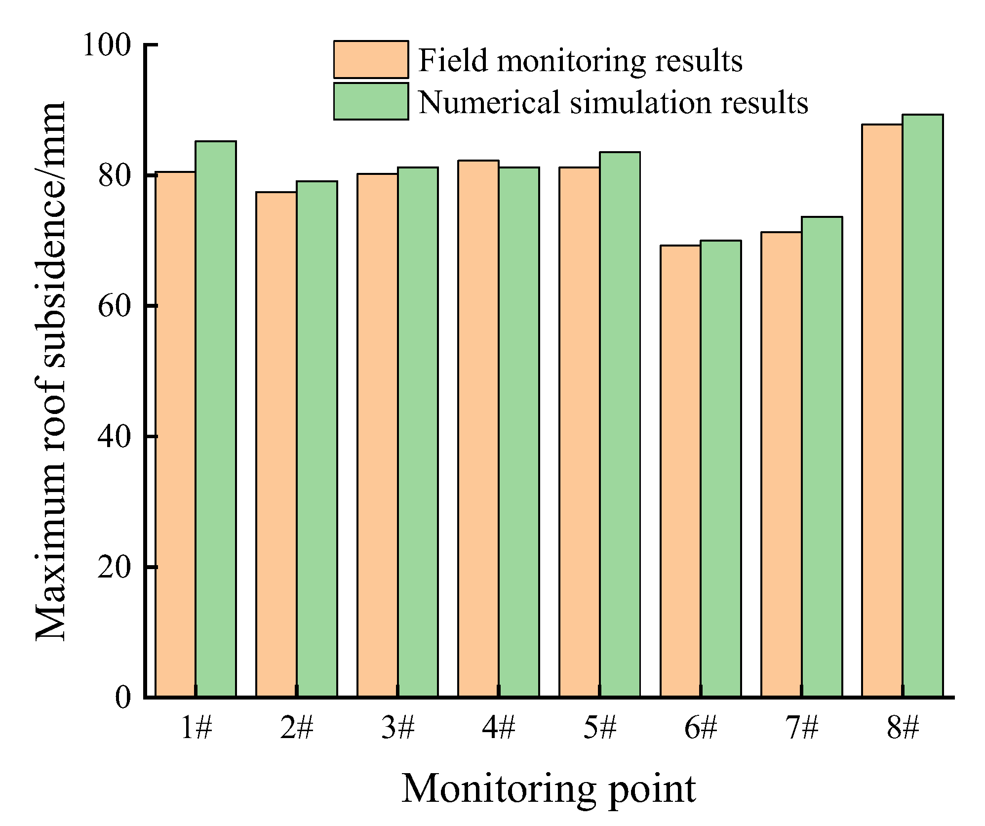
Figure 19.
Numerical simulation results versus the field monitoring results of the maximum roof subsidence.
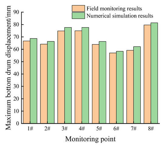
Figure 20.
Numerical simulation results versus the field monitoring results of the maximum bottom drum displacement.
For measuring stations numbers 2–7 located in the main position of the cavern, the deformation of the surrounding rock in the cavern can be divided into three stages over time. They are the rapid deformation stage, the slow deformation stage, and the stable deformation stage. Within 10 d after excavation, the cavern is at the stage of rapid deformation. The maximum roof subsidence, bottom drum displacement, and two-sided displacement are 31 mm, 24 mm, and 46 mm, respectively. On the 15th day, the support technology of LBG was applied, and the excavation cavern began to increase slowly, which belongs to the slow deformation stage. Roof subsidence, bottom drum displacement, and two-sided displacement are 54 mm, 52 mm, and 79 mm, respectively. The deformation of the surrounding rock is almost constant after 74–95 d of excavation, which is the stable stage of deformation.
For the No. 1 and No. 8 measuring stations at the intersection and the connection of the roadway, the roof subsidence of the surrounding rock and the two-sided displacement are 85 mm, 91 mm, 125 mm, and 130 mm, respectively, and the bottom drum displacements are 77 mm and 79 mm, respectively. This is because measuring stations 1 and 8 are located in the passageway, and the roadway deformation is large due to the influence of concentrated stress.
Meanwhile, Figure 16, Figure 17 and Figure 18 show the field-measured results are in good agreement with the numerical results. The monitoring results show that the deformation and failure of the surrounding rock in the cavern are obviously reduced by using a LBG control scheme. According to the peeping results of the drilling hole, the failure depth of the surrounding rock is only within 2 m of the surrounding rock, and there were no large tensile and shear failure areas. An anchor bolt and cable can play a better anchoring role. The novel support technology of a LBG can ensure the long-term stability of the cavern. There is no stratification within 2–15 m of the surface of the cavern.
6. Conclusions
In view of the problem of controlling the surrounding rock in large sections of whole coal cavern groups due to the influence of soft surrounding rock and a large section, this study proposes an innovative LBG support technology and obtains the following innovative conclusions, different from the perspective of improving the stress state of the surrounding rock:
- (1)
- A mechanical model for WCCG with a rectangular roadway is established and solved based on an equivalent circular method. The theoretical calculation results showed that the heights of a loose ring in the roof and its two sides are 3.34 m and 2.54 m, respectively. It provides guidance for determining the supporting parameters of the whole coal cavern group;
- (2)
- A numerical model under different section parameters is established for the linkage impact between whole coal cavern groups and the large section. With the increase of the lateral pressure coefficient, the stress concentration area on both sides of the caverns first increases laterally and then changes to a longitudinal diffusion. The plastic zone of the cavern tends to decrease with an increase in the lateral pressure coefficient. The range of the plastic zone decreases gradually on the two sides of the cavern, thus extending gradually to the top and bottom floors. The distribution of the plastic zone changed from stocky to tall. The stress and deformation mechanisms of the surrounding rock provide the basis for the control theory and parameters of the surrounding rock in the WCCG with a large section;
- (3)
- The surrounding rock of the whole coal cavern group presents an asymmetric pressure relief form due to the excavation of the cavern. Far away from the surface of the cavern, the stress gradually increases, and the stress concentration appears in the depths. The stress concentration on the two sides is greater than that on the top and bottom. In the shallow part of the surrounding rock, tensile failure or tensile shear failure mainly occurs, and shear failure mainly occurs in the deep part of the surrounding rock. The bearing capacity of the surrounding rock is greatly reduced due to the excavation of the cavern. It is necessary to improve its stability through active, strong support;
- (4)
- The stratified reinforcement ring concept of a LBG is proposed based on the obtained deformation mechanism to control surrounding rock deformation of the WCCG. The supporting technology of an anchor bolt (3 m), grouting anchor cable (8.3 m), and a long anchor cable (15 m) is proposed and adopted to connect the broken zone, the plastic zone, and the elastic zone in the gas storage cavern group with the large section. The roof subsidence and two-sided displacement are controlled at 140 mm and 120 mm, respectively, by using the supporting scheme of a LBG, and the surrounding rock deformation in the caverns is obviously reduced. The results of the numerical simulation and the field monitoring show that the LBG technology is effective for the stability control of the WCCG.
Author Contributions
Conceptualization, L.C. and Z.W.; methodology, Z.W.; software, L.C. and Z.W.; validation, L.C., W.W. and J.Z.; data curation, L.C. and Z.W.; supervision, W.W.; project administration, L.C., Z.W. and J.Z.; funding acquisition, Z.W. and J.Z. All authors have read and agreed to the published version of the manuscript.
Funding
The authors sincerely thank the following agents for their financial supports: the Scientific and Technological Project of Henan Province (222102320060), the Strength Improvement Plan of the Advantageous Disciplines of Zhongyuan University of Technology (SD202232), the Natural Science Foundation of China of Zhongyuan University of Technology (K2023QN013), the National Natural Science Foundation of China (52204264), and the Key Specialized Research and Development Breakthrough of Henan Province (222102320086).
Data Availability Statement
The data applied to support the results in this study are available from the corresponding author upon request.
Conflicts of Interest
The authors declare no conflict of interest.
References
- Du, F.; Wang, K.; Wang, G.; Huang, Y.; Yi, L. The mechanism of damage in gas-bearing coal-rock combination bodies and gas seepage in coals. Energy Sour. Part A Recovery Util. Environ. Eff. 2021, 43, 1181–1201. [Google Scholar] [CrossRef]
- Wang, W.; Wang, H.; Li, D.; Li, H.; Liu, Z. Strength and failure characteristics of naturaland water-saturated coal specimens under static and dynamic loads. Shock. Vib. 2018, 2018, 3526121. [Google Scholar]
- Du, F.; Ma, J.; Guo, X.; Wang, T.; Dong, X.; Li, J.; He, S.; Nuerjuma, D. Rockburst mechanism and the law of energy accumulation and release in mining roadway: A case study. Int. J. Coal Sci. Technol. 2022, 9, 1–17. [Google Scholar] [CrossRef]
- Zhang, J.; Li, B.; Liu, Y.; Li, P.; Fu, J.; Chen, L.; Ding, P. Dynamic multifield coupling model of gas drainage and a new remedy method for borehole leakage. Acta Geotech. 2022, 17, 4699–4715. [Google Scholar] [CrossRef]
- Li, B.; Zhang, J.; Liu, Y.; Qu, L.; Liu, Q.; Sun, Y.; Xu, G. Interfacial porosity model and modification mechanism of broken coal grouting: A theoretical and experimental study. Surf. Interfaces 2022, 33, 102286. [Google Scholar] [CrossRef]
- Bai, Q.; Tu, S.; Wang, F.; Zhang, C. Field and numerical investigations of gateroad system failure induced by hard roofs in a longwall top coal caving face. Int. J. Coal Geol. 2017, 173, 176–199. [Google Scholar] [CrossRef]
- Chen, H.D.; Chen, X.J.; Wang, Z.F.; Li, Z.; An, F. Plastic zone range of a roadway considering the creep effect. Sci. Rep. 2020, 10, 20341. [Google Scholar] [CrossRef]
- Zhang, Z.; Deng, M.; Bai, J.; Yan, S.; Yu, X. Stability control of gob-side entry retained under the gob with close distance coal seams. Int. J. Min. Sci. Technol. 2021, 31, 321–332. [Google Scholar] [CrossRef]
- Yuan, L.; Xue, J.H.; Liu, Q.S.; Liu, B. Surrounding rock stability control theory and support technique in deep rock roadway for coal mine. Meitan Xuebao/J. China Coal Soc. 2011, 36, 535–543. [Google Scholar]
- Kang, H. Sixty year’development and prospects of rock bolting technology for underground coal mine roadways in China. J. China Univ. Min. Technol. 2016, 45, 1071–1081. [Google Scholar]
- He, M.; Gong, W.; Wang, J.; Qi, P.; Tao, Z.; Du, S.; Peng, Y. Development of a novel energy-absorbing bolt with extraordinarily large elongation and constant resistance. Int. J. Rock Mech. Min. Sci. 2014, 67, 29–42. [Google Scholar] [CrossRef]
- Sun, X.M.; Zhang, G.F.; Cai, F.; Yu, S.B. Asymmetric deformation mechanism within inclinde rock strata induced by excavation in deep roadway and its controlling countermeasure. Chin. J. Rock Mech. Eng. 2009, 28, 1137–1143. [Google Scholar]
- Deng, J.Q.; Yang, Q.; Liu, Y.R.; Pan, Y.W. Stability evaluation and failure analysis of rock salt gas storage caverns based on deformation reinforcement theory. Comput Geotech. 2015, 68, 147–160. [Google Scholar] [CrossRef]
- Moghadam, S.N.; Nazokkar, K.; Chalaturnyk, R.J.; Mirzabozorg, H. Parametric assessment of salt cavern performance using a creep model describing dilatancy and failure. Int. J. Rock Mech. Min. 2015, 79, 250–267. [Google Scholar] [CrossRef]
- Wang, T.; Yang, C.; Ma, H.; Li, Y.; Shi, X.; Li, J.; Daemen, J.J.K. Safety evaluation of salt cavern gas storage close to an old cavern. Int. J. Rock Mech. Min. 2016, 83, 95–106. [Google Scholar] [CrossRef]
- Kang, H.P. Spatial scale analysis on coal mining and strata control technologies. J. Min. Strat. Control Eng. 2020, 2, 5–30. [Google Scholar]
- Kang, H.P. Temporal scale analysis on coal mining and stratac ontroltechnologies. J. Min. Strat. Control Eng. 2021, 3, 013538. [Google Scholar]
- Pan, Y.S.; Lv, X.F.; Li, Z.H.; Dai, S. Experimental study of dynamic failure process of roadway under high velocity impact loading. Rock Soil Mech. 2011, 32, 1281–1286. [Google Scholar]
- Wang, S.W.; Liu, H.D.; Jiang, T. Large geomechanical model test on failure mechanism of rockburst tunnel under static and explosive loads. Chin. J. Rock Mech. Eng. 2014, 33, 2095–2100. [Google Scholar]
- Shreedharan, S.; Kulatilake, P.H.S.W. Discontinuum-Equivalent continuum analysis of the stability of tunnels in a deep coal mine using the distinct element method. Rock Mech. Rock Eng. 2016, 49, 1903–1922. [Google Scholar] [CrossRef]
- Deng, J.Q.; Yang, Q.; Liu, Y.R. Time-dependent behavior and stability evaluation of gas storage caverns in salt rock based on deformation reinforcement theory. Tunn. Undergr. Sp. Tech. 2014, 42, 277–292. [Google Scholar] [CrossRef]
- Wu, H.; Jia, Q.; Wang, W.; Zhang, N.; Zhao, Y. Experimental test on nonuniform deformation in the tilted strata of a deep coal mine. Sustainability 2021, 13, 13280. [Google Scholar] [CrossRef]
- Zhao, Y.; Liu, Q.; Zhang, C.; Liao, J.; Lin, H.; Wang, Y. Coupled seepage-damage effect in fractured rock masses: Model development and a case study. Int. J. Rock Mech. Min. Sci. 2021, 144, 104822. [Google Scholar] [CrossRef]
- Wang, Q.; Zhan, H.J.; Jiang, B.; Huang, Y.B.; Zhang, P.; Xu, S.; Liu, B.H. Failure mechanism of deep large section cavern and anchor injection control method. J. Min. Saf. Eng. 2020, 37, 1094–1103. [Google Scholar]
- Wang, Q.; Jiang, B.; Pan, R.; Li, S.-C.; He, M.-C.; Sun, H.-B.; Qin, Q.; Yu, H.-C.; Luan, Y.-C. Failure mechanism of surrounding rock with high stress and con-fined concrete support system. Int. J. Rock Mech. Min. Sci. 2018, 102, 89–100. [Google Scholar] [CrossRef]
- Wang, Q.; Gao, H.; Yu, H.; Jiang, B.; Liu, B. Method for measuring rock mass characteristics and evaluating the grouting reinforced effect based on digital drilling. J. Rock Mech. Rock Eng. 2019, 52, 841–851. [Google Scholar] [CrossRef]
- Hou, C.J. Effective approach for surrounding rock control in deep roadway. J. China Univ. Min. Technol. 2017, 46, 577–583. [Google Scholar]
- He, M.C.; Li, G.F.; Ren, A.W.; Yang, J. Analysis of the stability of intersecting caverns in deep soft-rock roadway construction. J. China Univ. Min. Technol. 2008, 37, 167–170. [Google Scholar]
- Yang, R.S.; Xue, J.H.; Guo, D.M.; Li, Y. Failure mechanism of surrounding rock of large section caverns in complex rock formations and its control. J. China Coal Soc. 2015, 40, 2234–2242. [Google Scholar]
- Kang, Y.; Liu, Q.; Gong, G.; Wang, H. Application of a combined support system to the weak floor reinforcement in deep underground coal mine. Int. J. Rock Mech. Min. Sci. 2014, 71, 143–150. [Google Scholar] [CrossRef]
- Jiao, Y.Y.; Song, L.; Wang, X.Z.; Adoko, A.C. Improvement of the U-shaped steel sets for supporting the roadways in loose thick coal seam. Int. J. Rock Mech. Min. Sci. 2013, 60, 19–25. [Google Scholar] [CrossRef]
- Li, X.H.; Yao, Q.L.; Zhang, N. Fracture characteristics of a soft rock roadway: Staged and zoned control. J. China Univ. Min. Technol. 2009, 38, 618–623. [Google Scholar]
- Li, S.C.; Wang, H.T.; Wang, Q.; Jiang, B.; Wang, F.Q.; Guo, N.B.; Liu, W.; Ren, Y.X. Failure mechanism of bolting support and high-strength bolt-grouting technology for deep and soft surrounding rock with high stress. J. Cent. South Univ. 2016, 23, 440–448. [Google Scholar] [CrossRef]
- Singh, R.P.; Mousumi, M.; Verma, M.K. Studies on the failure behavior of wire rope used in underground coal mines. Eng. Fail Anal. 2016, 70, 290–304. [Google Scholar] [CrossRef]
- Ram, S.; Kumar, D.; Singh, A.K.; Kumar, A.; Singh, R. Field and numerical modelling studies for an efficient placement of roof bolts as breaker line support. Int. J. Rock Mech. Min. Sci. 2017, 93, 152–162. [Google Scholar] [CrossRef]
- Yuan, Z.; Zhao, J.; Li, S.; Jiang, Z.; Huang, F. A unified solution for surrounding rock of roadway considering seepage, dilatancy, strain-softening and intermediate principal stress. Sustainability 2022, 14, 8099. [Google Scholar] [CrossRef]
- Yu, W.; Li, K.; Liu, Z.; An, B.; Wang, P.; Wu, H. Mechanical characteristics and deformation control of surrounding rock in weakly cemented siltstone. Environ. Earth Sci. 2021, 80, 337. [Google Scholar] [CrossRef]
- Zheng, P.Q.; Liu, Y.Q.; Zhan, Z.W. Research on support optimization of rectangular roadway based on equivalent circle method. Coal Technol. 2022, 41, 10–13. [Google Scholar]


Disclaimer/Publisher’s Note: The statements, opinions and data contained in all publications are solely those of the individual author(s) and contributor(s) and not of MDPI and/or the editor(s). MDPI and/or the editor(s) disclaim responsibility for any injury to people or property resulting from any ideas, methods, instructions or products referred to in the content. |
© 2023 by the authors. Licensee MDPI, Basel, Switzerland. This article is an open access article distributed under the terms and conditions of the Creative Commons Attribution (CC BY) license (https://creativecommons.org/licenses/by/4.0/).