
Variable Universe Fuzzy Controller for an Independent Metering System of Construction Machinery
Abstract
:1. Introduction
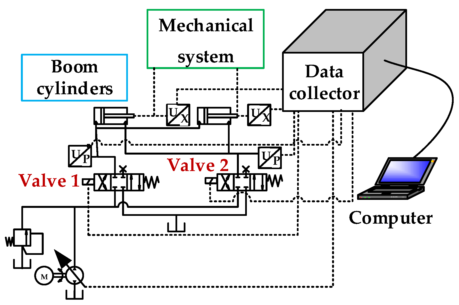
2. Studied System and Its Application in an Excavator
2.1. Application of the IMCS in an Excavator
2.2. Models of Components in the IMCS
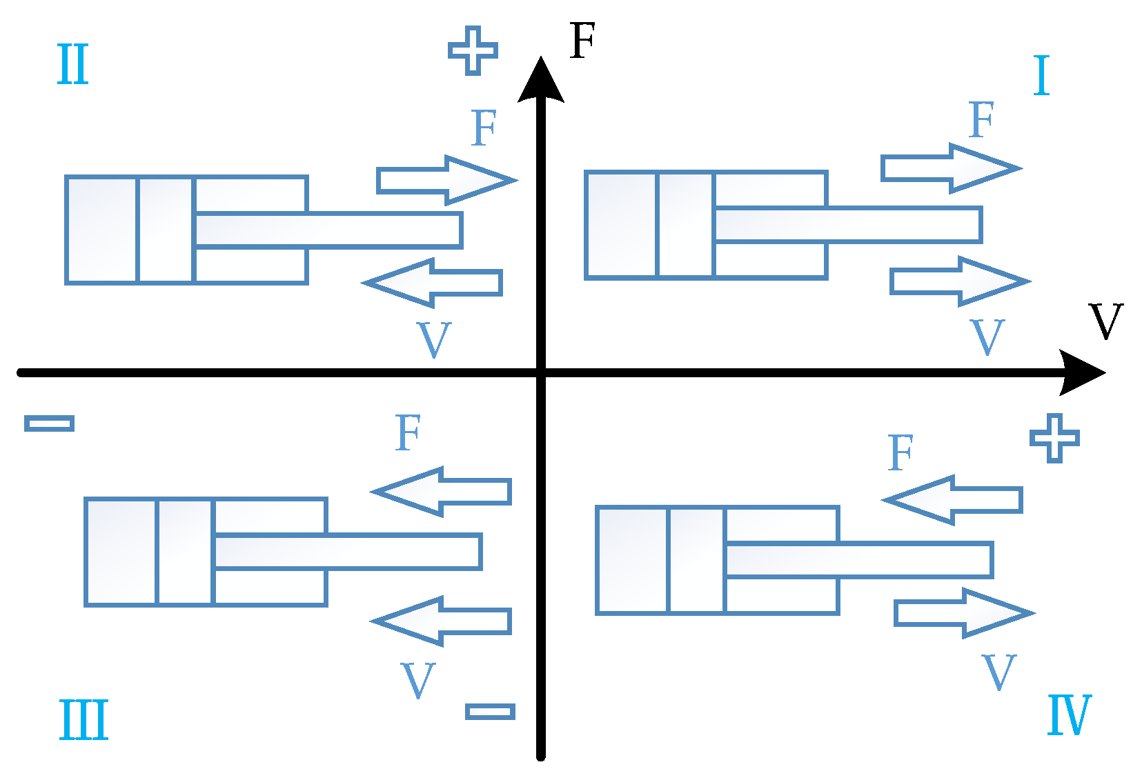
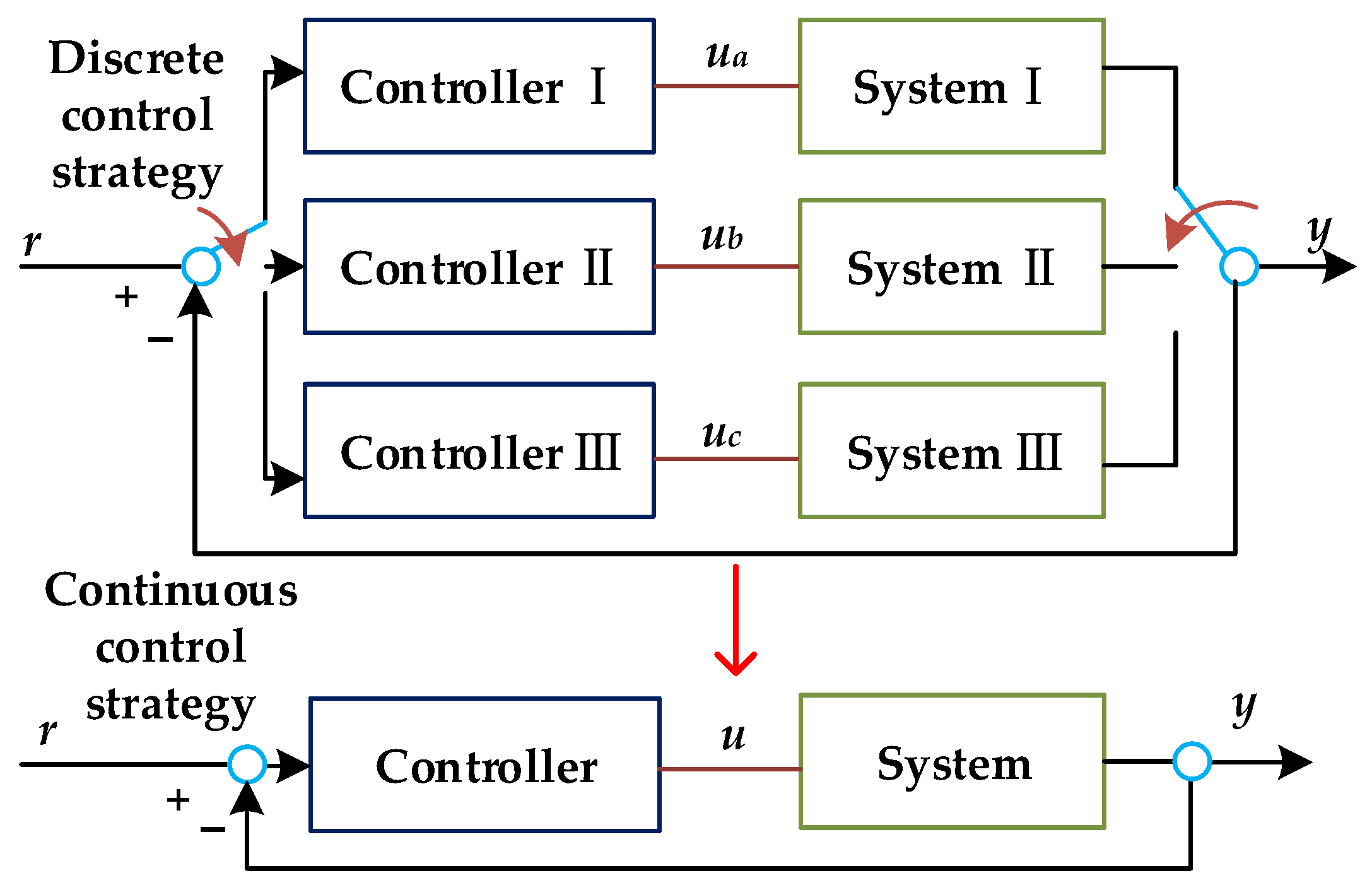
3. Problem Statement
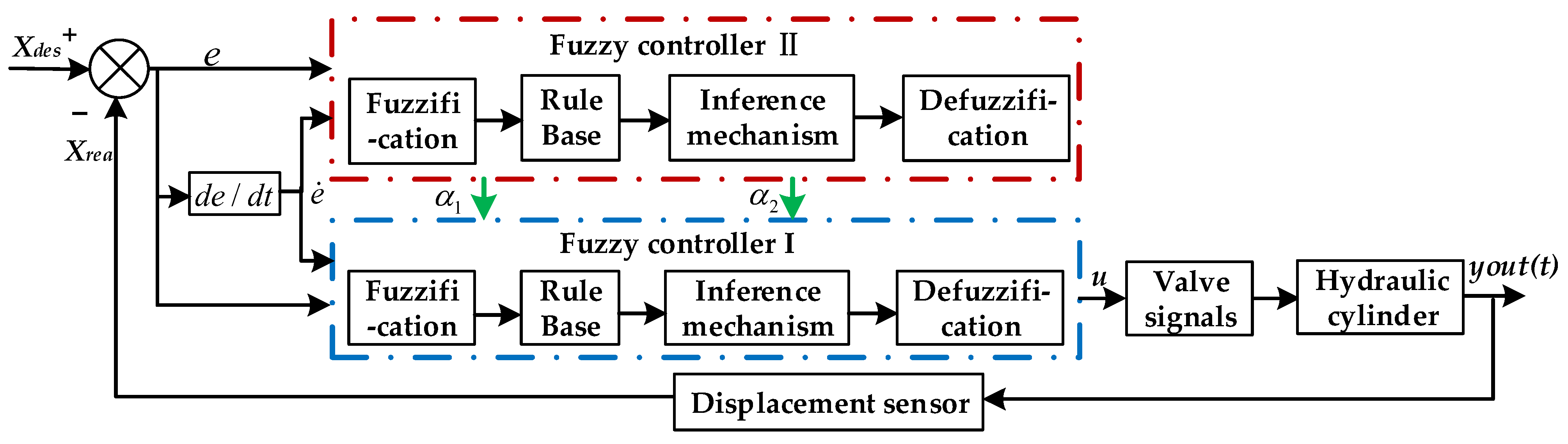
4. Variable Universe Fuzzy Controller Design
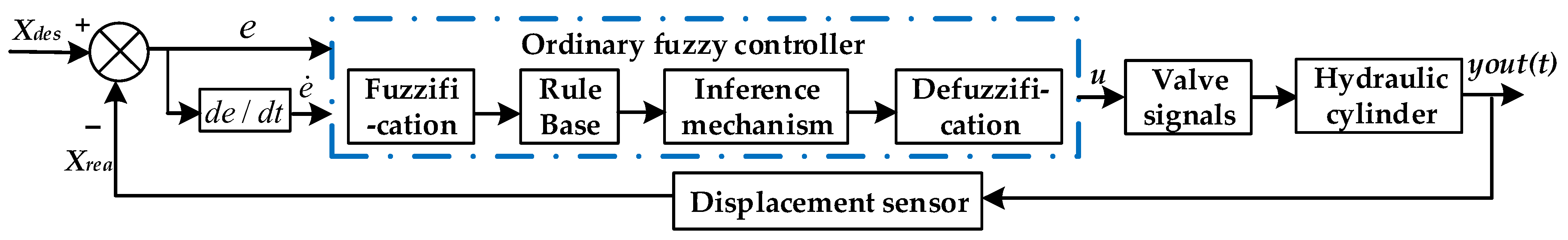
4.1. Basic Principle of the Variable Universe Fuzzy Controller Based on Fuzzy Reasoning
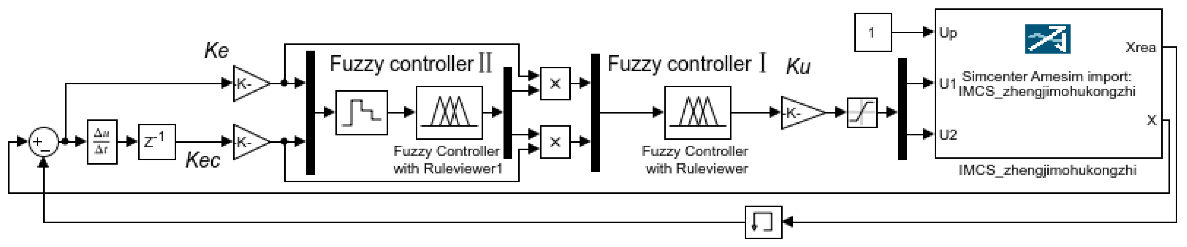
4.2. Design Process of the Variable Universe Fuzzy Controller
4.2.1. Design Process of Controller I
- 1.
- Select the word set of input and output variables
- 2.
- Determine the quantization factor and output scale factor
- 3.
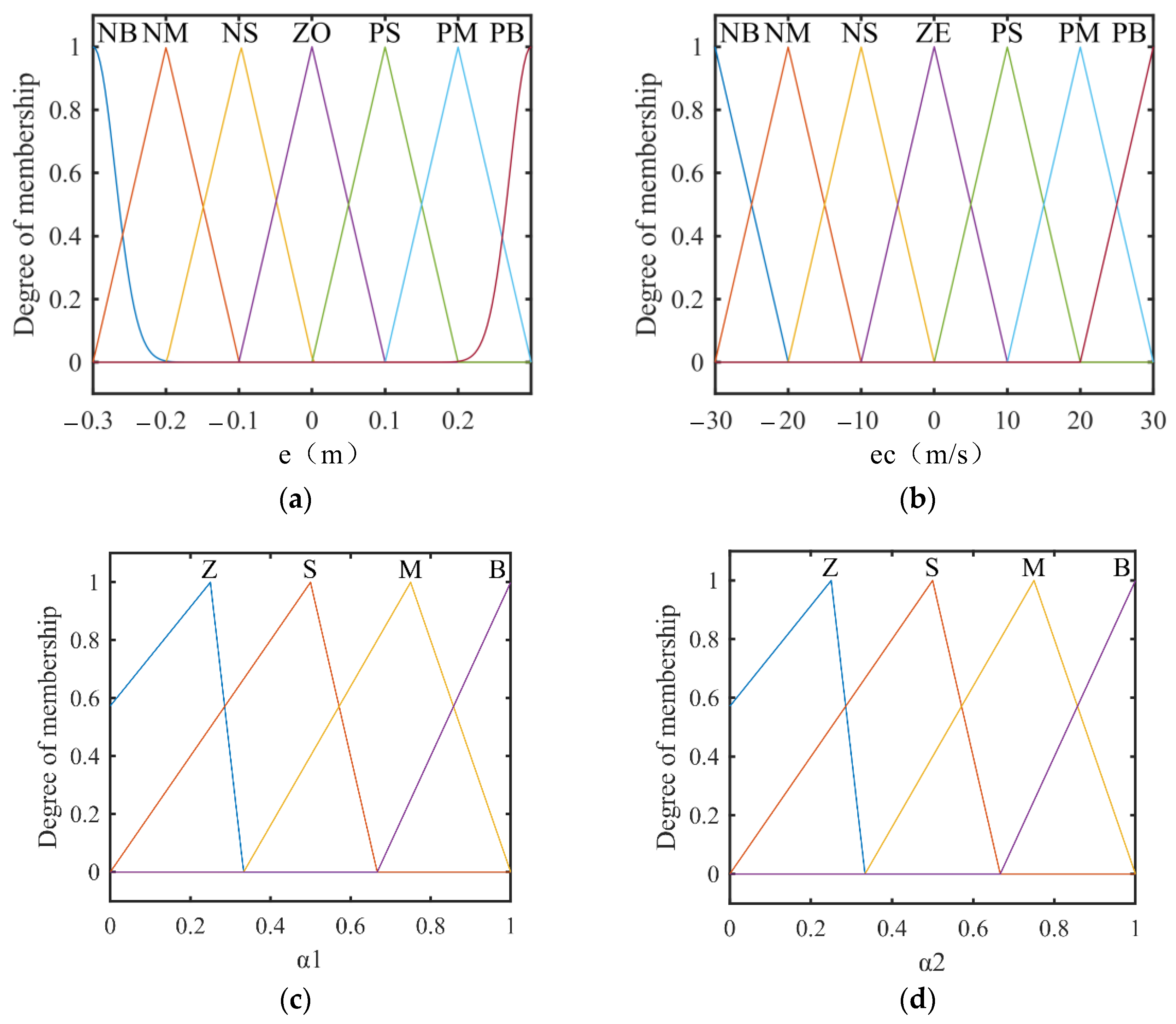
- Determine the membership function of the fuzzy variables
- 4.
- Fuzzy rule design of the fuzzy controller I
- 5.
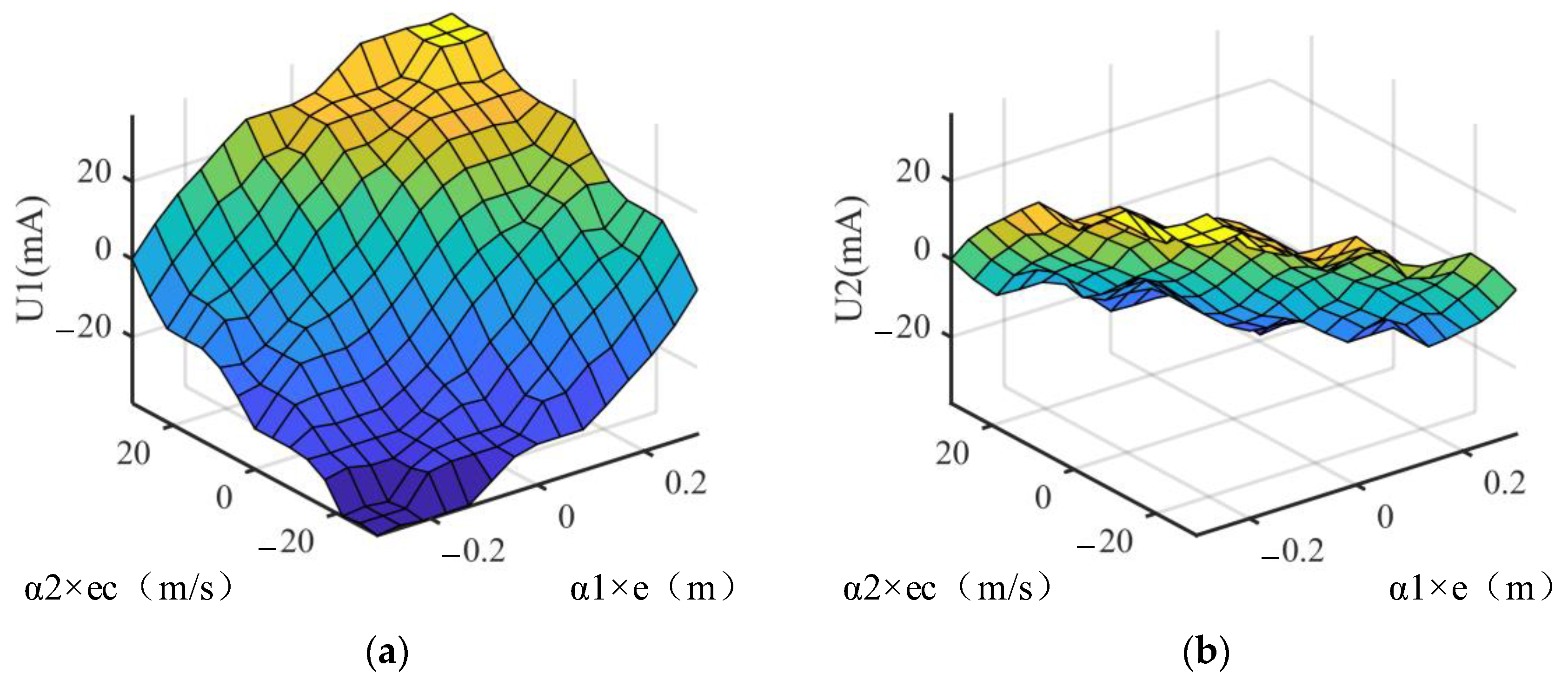
- The mapping relationship between the input and the output of the fuzzy controller I
4.2.2. Design Process of Controller II
- 1.
- Select the word set of input and output variables
- 2.
- Determine the quantization factor and output scale factor
- 3.
- Determine the membership function of the fuzzy variables
- 4.
- Fuzzy rule design of the fuzzy controller II
- 5.
- Mapping relationship between the input and the output of the fuzzy controller II.
5. Test Research
6. Discussion and Conclusions
Author Contributions
Funding
Data Availability Statement
Conflicts of Interest
References
- Xiao, Q.; Wang, Q.; Zhang, Y. Control strategies of power system in hybrid hydraulic excavator. Autom. Constr. 2008, 17, 361–367. [Google Scholar] [CrossRef]
- Shi, H.; Yang, H.; Gong, G.; Liu, H.; Hou, D. Energy saving of cutterhead hydraulic drive system of shield tunneling machine. Autom. Constr. 2014, 37, 11–21. [Google Scholar] [CrossRef]
- Ding, R.; Zhang, J.; Xu, B.; Cheng, M. Programmable hydraulic control technique in construction machinery: Status, challenges and countermeasures. Autom. Constr. 2018, 95, 172–192. [Google Scholar] [CrossRef]
- Mattila, J.; Koivumaki, J.; Caldwell, D.G.; Semini, C. A Survey on Control of Hydraulic Robotic Manipulators With Projection to Future Trends. IEEE/ASME Trans. Mechatron. 2017, 22, 669–680. [Google Scholar] [CrossRef]
- Edge, K. The control of fluid power systems-responding to the challenges. Proc. Inst. Mech. Eng. Part I 1997, 211, 91–110. [Google Scholar] [CrossRef]
- Eriksson, B.; Palmberg, J.-O. Individual metering fluid power systems: Challenges and opportunities. Proc. Inst. Mech. Eng. Part I J. Syst. Control Eng. 2011, 225, 196–211. [Google Scholar] [CrossRef]
- Weber, J.; Beck, B.; Fischer, E.; Ivantysyn, R.; Kolks, G.; Kunkis, M.; Lohse, H.; Lübbert, J.; Michel, S.; Schneider, M.; et al. Novel system architectures by individual drives. In Proceedings of the 10th International Fluid Power Conference, IFK Conference Proceedings, Dresden, Germany, 9 March 2016; Volume 2. [Google Scholar]
- Hansen, A.H.; Pedersen, H.C.; Andersen, T.O.; Wachmann, L. Investigation of energy saving separate meter-in and separate meter-out control strategies. In Proceedings of the Twelfth Scandinavian International Conference on Fluid Power, Tampere, Finland, 18–20 May 2011; pp. 1–15. [Google Scholar]
- Aardema, J.A.; Koehler, D.W. System and Method for Controlling an Independent Metering Valve. U.S. Patent 5,947,140, 7 September 1999. [Google Scholar]
- Hajek, T.J., Jr.; Tolappa, S.T. Independent and Regenerative Mode Fluid Control System. U.S. Patent 6,715,403, 6 April 2004. [Google Scholar]
- Lübbert, D.-I.J.; Sitte, D.-I.A.; Weber, I.J. Pressure compensator control a novel independent metering architecture. In Proceedings of the 10th International Fluid Power Conference, Aachen, Germany, 8–10 March 2016; Volume 1, pp. 231–245. [Google Scholar]
- Sitte, A.; Weber, J. Structural design of independent metering control systems. In Proceedings of the 13th Scandinavian International Conference on Fluid Power, Linköping, Sweden, 3–5 June 2013; Linköping University Electronic Press: Linköping; Sweden, 2013; pp. 261–270. [Google Scholar]
- Opdenbosch, P.; Sadegh, N.; Book, W.; Enes, A. Auto-calibration based control for independent metering of hydraulic actuators. In Proceedings of the IEEE International Conference on Robotics and Automation, Shanghai, China, 9–13 May 2011; pp. 153–158. [Google Scholar]
- Lyu, L.; Chen, Z.; Yao, B. Energy Saving Motion Control of Independent Metering Valves and Pump Combined Hydraulic System. IEEE/ASME Trans. Mechatron. 2019, 24, 1909–1920. [Google Scholar] [CrossRef]
- Zaev, E.; Rath, G.; Kargl, H. Energy Efficient Active Vibration Damping. In Proceedings of the 13th Scandinavian International Conference on Fluid Power, Linköping, Sweden, 3–5 June 2013. [Google Scholar]
- Zhang, X.; Qiao, S.; Quan, L.; Ge, L. Velocity and Position Hybrid Control for Excavator Boom Based on Independent Metering System. IEEE Access 2019, 7, 71999–72011. [Google Scholar] [CrossRef]
- Shi, J.; Quan, L.; Zhang, X.; Xiong, X. Electro-hydraulic velocity and position control based on independent metering valve control in mobile construction equipment. Autom. Constr. 2018, 94, 73–84. [Google Scholar] [CrossRef]
- Zhang, Y.; Alleyne, A.; Zheng, D. A hybrid control strategy for active vibration isolation with electrohydraulic actuators. Control Eng. Pract. 2005, 13, 279–289. [Google Scholar] [CrossRef]
- Xu, B.; Cheng, M.; Yang, H.; Zhang, J.; Shuang, C. A hybrid displacement/pressure control scheme for an electrohydraulic flow matching system. IEEE/ASME Trans. Mechatron. 2015, 20, 2771–2782. [Google Scholar] [CrossRef]
- Heybroek, K. Saving Energy in Construction Machinery Using Displacement Control Hydraulics—Concept Realization and Validation; Linköping University: Linköping, Sweden, 2008. [Google Scholar]
- Linjama, M.; Huova, M.; Vilenius, M. Digital fluid power-state of the art. In Proceedings of the 12th Scandinavian International Conference on Fluid Power, Tampere University of Technology, Tampere, Finland, 18–20 May 2011; Sairiala, H., Ed.; Scandinavian International Conference on Fluid Power: Tampere, Finland. ISBN 978-952-15-2520-9. [Google Scholar]
- Huova, M.; Linjama, M. Energy efficient digital hydraulic valve control utilizing pressurized tank line. In Proceedings of the 8th International Fluid Power Conference, Dresden University of Technology, Dresden, Germany, 26–28 March 2012; pp. 111–122. Available online: https://tutcris.tut.fi/portal/en/publications/energy-efficient-digitalhydraulic-valve-control-utilizing-pressurized-tank-line(e8547b76-df73-4814-9e43-a89763ba3722).html (accessed on 29 December 2022).
- Heybroek, K.; Larsson, J.; Palmberg, J. Mode switching and energy recuperation in open circuit pump control. In Proceedings of the 10th Scandinavian International Conference on Fluid Power, Tampere, Finland, 21–23 May 2007; pp. 197–209. [Google Scholar]
- Heybroek, K.; Palmberg, J. Applied control strategies for a pump controlled open circuit solution. In Proceedings of the 6th IFK: International Fluid Power Conference, Dresden, Germany, 31 March–2 April 2008; pp. 39–52. [Google Scholar]
- Graebe, S.; Ahlen, A. Dynamic transfer among alternative controllers and its relation to antiwindup controller design. IEEE Trans. Control Syst. Technol. 1996, 4, 92–99. [Google Scholar] [CrossRef]
- Lin, H.; Antsaklis, P.J. Stability and Stabilizability of Switched Linear Systems: A Survey of Recent Results. IEEE Trans. Autom. Control 2009, 54, 308–322. [Google Scholar] [CrossRef]
- Ding, R.; Xu, B.; Zhang, J.; Cheng, M. Bumpless mode switch of independent metering fluid power system for mobile machinery. Autom. Constr. 2016, 68, 52–64. [Google Scholar] [CrossRef]
- Shenouda, A. Quasi-static Hydraulic Control Systems and Energy Savings Potential Using Independent Metering Four-Valve Assembly Configuration; Georgia Institute of Technology: Atlanta, GA, USA, 2006. [Google Scholar]
- Wu, Y. Design and Online Implementation of Improved Fuzzy Controller for Electro-Hydraulic Position Servo System. Master’s Thesis, Wuhan University of Science and Technology, Wuhan, China, 2008. [Google Scholar]
- Yang, X. Research on Control Strategy of New Electro-Hydraulic Proportional Multi-Way Valve for Excavator. Master’s Thesis, Central South University, Changsha, China, 2008. [Google Scholar]
- Li, L. Research on Variable Universe Fuzzy Control Algorithm. Master’s Thesis, University of Electronic Science and Technology, Chengdu, China, 2008. [Google Scholar]


| U1 | E | |||||||
| NB | NM | NS | ZO | PS | PM | PB | ||
| EC | NB | PB | PB | PM | PM | PS | PS | ZO |
| NM | PB | PB | PM | PS | PS | ZO | NS | |
| NS | PB | PM | PM | PS | ZO | NS | NM | |
| ZO | PM | PM | PS | ZO | NS | NM | NM | |
| PS | PM | PS | ZO | NS | NM | NM | NB | |
| PM | PS | ZO | NS | NS | NM | NB | NB | |
| PB | ZO | NS | NS | NM | NM | NB | NB | |
| U2 | E | |||||||
| NB | NM | NS | ZO | PS | PM | PB | ||
| EC | NB | NB | NB | NB | NM | NM | NS | ZO |
| NM | NB | NB | NM | NM | NS | ZO | PS | |
| NS | NM | NM | NM | NS | ZO | PS | PS | |
| ZO | NM | NS | NS | ZO | PS | PS | PM | |
| PS | NS | NS | ZO | PS | PM | PM | PM | |
| PM | NS | ZO | PS | PM | PM | PB | PB | |
| PB | ZO | PS | PM | PM | PB | PB | PB | |
| α1 | E | |||||||
| NB | NM | NS | ZO | PS | PM | PB | ||
| EC | NB | B | B | M | S | M | B | B |
| NM | B | M | S | S | S | M | B | |
| NS | M | M | S | Z | Z | M | M | |
| ZO | M | S | Z | Z | Z | S | M | |
| PS | M | M | S | Z | S | M | M | |
| PM | B | M | S | S | S | M | B | |
| PB | B | B | M | S | M | B | B | |
| α2 | E | |||||||
| NB | NM | NS | ZO | PS | PM | PB | ||
| EC | NB | B | B | M | S | M | B | B |
| NM | B | M | S | S | S | M | B | |
| NS | M | M | S | Z | Z | M | M | |
| ZO | M | S | Z | Z | Z | S | M | |
| PS | M | M | S | Z | S | M | M | |
| PM | B | M | S | S | S | M | B | |
| PB | B | B | M | S | M | B | B | |
Disclaimer/Publisher’s Note: The statements, opinions and data contained in all publications are solely those of the individual author(s) and contributor(s) and not of MDPI and/or the editor(s). MDPI and/or the editor(s) disclaim responsibility for any injury to people or property resulting from any ideas, methods, instructions or products referred to in the content. |
© 2023 by the authors. Licensee MDPI, Basel, Switzerland. This article is an open access article distributed under the terms and conditions of the Creative Commons Attribution (CC BY) license (https://creativecommons.org/licenses/by/4.0/).
Share and Cite
Hu, S.; Wang, L.; Li, Y.; Zhang, L. Variable Universe Fuzzy Controller for an Independent Metering System of Construction Machinery. Processes 2023, 11, 901. https://doi.org/10.3390/pr11030901
Hu S, Wang L, Li Y, Zhang L. Variable Universe Fuzzy Controller for an Independent Metering System of Construction Machinery. Processes. 2023; 11(3):901. https://doi.org/10.3390/pr11030901
Chicago/Turabian StyleHu, Shuang, Lihang Wang, Yongquan Li, and Lijie Zhang. 2023. "Variable Universe Fuzzy Controller for an Independent Metering System of Construction Machinery" Processes 11, no. 3: 901. https://doi.org/10.3390/pr11030901