3.1. Establishment of EV Power System Mathematical Model
FCEVs can be separated into pure FC vehicles and hybrid EVs according to the energy composition [
20]. The hybrid power system of the FC and the power cell is the power system widely used by major automobile manufacturers [
21]. Among them, the power cell is the auxiliary energy source, and the FC is the primary energy source. The FC is the average power required by the vehicle system. The power battery provides the difference between the maximum power and the average power, which greatly reduces the volume of the FC and reduces the cost of the vehicle [
22]. The power battery module has good continuous tracking output performance under the condition of drastic load changes. This can effectively compensate for the transient changes of the FC and effectively reduce the dynamic changes of the FC, thus improving the service life [
23,
24]. The energy generated by the automobile brake is input to the battery through the bus, thus reducing the hydrogen consumption of the system and improving the economy of the whole vehicle.
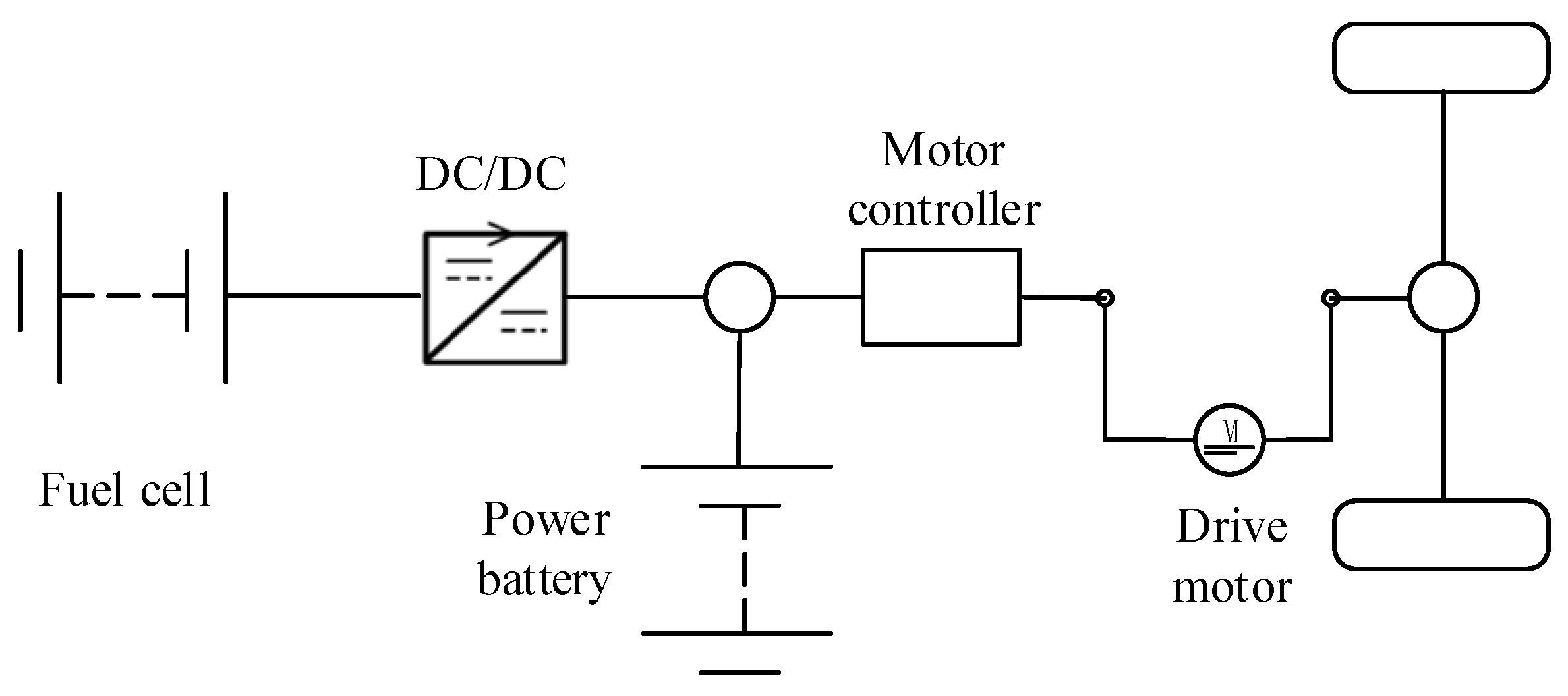
Figure 1 depicts the hybrid system structure of a FCEV.
The cost-effectiveness of the hybrid system of the FC and the power battery is higher than that of the pure FC. Therefore, the power system is selected for optimization [
25]. In this power system, the energy of the vehicle is provided by the power battery, FC, and DC/DC converter. The power battery’s primary purpose is to supply the momentary maximum power demand so that the system can maintain stable output power for a long time. To optimize the capacity of the power battery better, the power system model of the vehicle is built first. Considering the economy and practicability of FCEVs, the constructed vehicle dynamics model includes only the longitudinal dynamics model of driving and braking, not the vehicle’s vibration and driving stability. The expression of vehicle demand torque
is shown in Formula (1) [
26].
In Formula (1),
represents the wheel radius and the unit is m. The EV’s mass is
and the unit is kg.
is the acceleration of gravity and the unit is m/s
2. The rolling resistance coefficient is
and the unit is
.
is the speed of the EV and the unit is km/h.
is the air resistance coefficient and the unit is ns/m. The windward area is
and the unit is m
2.
is the air density and the unit is kg/m
3.
is the road slope.
is the final drive ratio.
represents the transmission efficiency.
represents the coefficient of rotation. To optimize the capacity of the power battery, the vehicle’s total mass is made up of the mass of the vehicle itself and the mass of the power battery pack. The expression of the total vehicle mass
is shown in Formula (2).
In Formula (2), the basic mass of the car is
and the unit is kg.
is the mass of a single power battery and the unit is kg.
represents the number of power batteries.
Table 2 shows the main parameters of a FCEV [
27].
The drive motor is an important part of new energy vehicles and also a source of power [
28,
29]. Special drive motors for new energy vehicles include DC motors, asynchronous motors, permanent magnet synchronous motors, and switched reluctance motors. Due to their high efficiency, easy control, wide speed range, high reliability, and high specific power, permanent magnet synchronous motors are commonly applied in new energy vehicles. Therefore, a permanent magnet synchronous motor is selected as the driving motor. Power batteries and fuel cells together power the drive motor. The two are effectively converted into mechanical energy to meet the torque
required by the vehicle. In addition, the friction brake
can be supplemented when the maximum battery current or torque is reached. The selected drive motor model is TX115MS156. The maximum torque, minimum torque, and maximum speed are 330 Nm, −330 Nm, and 12,000 rpm, respectively. The torque and required power of the motor are shown in Formula (3).
In Formula (3),
represents the motor power and the unit is kw.
represents the motor speed and the unit is r/min. The transmission system outputs the motor power to the wheels, giving the car power its needs. The relationship between the required power
of the car and the motor power
is shown in Formula (4).
In Formula (4),
represents the efficiency of the motor system. Formula (5) represents the dynamic system balance.
In Formula (5),
represents the fuel cell power.
denotes the battery power in watts.
is the power battery power loss.
is a constant representing the auxiliary power of the vehicle. All three power units are kw. The primary goal of the research is to improve the power battery of the hybrid power system. The power battery usually refers to the battery that provides the power source for pure EVs, hybrid EVs, fuel cell EVs, etc. At present, power batteries include lead acid, lithium ion, nickel metal hydride, etc. [
28]. The lithiumion battery is an ideal power battery for EVs at present due to its high voltage, long charging and discharging time, high specific energy, wide working range, safety and reliability, and fast charging. As the core component of a FCEV, the power battery can not only overcome the defect of poor dynamic characteristics but also effectively control the brake mechanism to make sure the car runs reliably and safely [
30,
31]. Detailed information of the selected power batteries is shown in
Table 3.
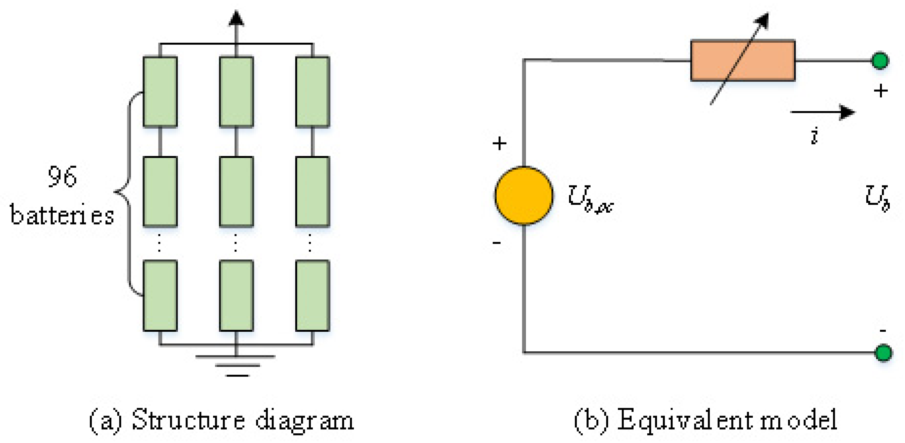
The existing equivalent models mainly include RC, Rint, lead acid (LA), and neural network (NN). The Rint model can reflect both the open-circuit voltage (OCV) and the charging/discharging internal resistance, making it convenient for conducting this experiment. Therefore, the Rint model is used as the equivalent model for this experiment. The Rint model is composed of a voltage source and a variable resistor. The equivalent model and structure of the power battery pack are shown in
Figure 2.
The structure of the power battery pack is shown in
Figure 2a.
Figure 2b is an equivalent model. From
Figure 2a, the quantity of batteries in series is 96 and the batteries in parallel are 3. According to Kirchhoff’s voltage law, Formula (6) displays the equivalent circuit’s equation.
In Formula (6),
represents the OCV of the power battery and the unit is V.
represents the internal resistance of the power battery and the unit is Ω.
represents the terminal voltage of the power battery and the unit is V.
represents the internal current of the power battery and the unit is A. The internal resistance
of the power battery is a function of the state of charge (SOC). The expression is shown in Formula (7).
In Formula (7),
is the internal resistance of power battery charging and the unit is Ω.
is the internal resistance of power battery discharge and the unit is Ω. When charging an electric vehicle, the resistance of the battery gradually decreases. When discharging an electric vehicle, the resistance of the battery gradually increases [
32]. The expression of the power battery OCV is shown in Formula (8).
In Formula (8),
is the lookup function of the SOC. Depending on the established mathematical model, a method for solving the optimal control problem of the dynamic model is proposed. It is to achieve the optimal matching of energy through the energy distribution within a certain driving time. On the premise of ensuring energy density, hydrogen consumption is reduced. The kinetic equation of the system is shown in Formula (9).
In Formula (9), represents the battery capacity and the unit is Wh. Formula (9) is the model of the dynamic system. Based on this model, an optimization operation is carried out to improve the performance of the power battery.
3.2. Power Battery Optimization Strategy Based on COA
COA is the most commonly used mathematical method in optimal control at present. This optimization strategy is based on CS and CF. It has been widely used in automobile intelligent control, smart home systems, financial statistics, etc. COA is a method to study the minimum problem of convex function under the given form [
33]. COA is more likely to be able to solve a problem if it can be made into a convex optimization problem or if it already is one. At present, local approximation of the general nonlinear optimization model by the convex optimization model is the main way to study problems with nonlinear optimization. In the optimization control of new energy vehicles, the COA also gradually shows its advantages. The CS in the COA means that if a set still contains the line segment connecting any two points, this set is called a CS. Generally speaking, if each point in a set can be reached by a line segment composed of any other point, the set is called a CS.
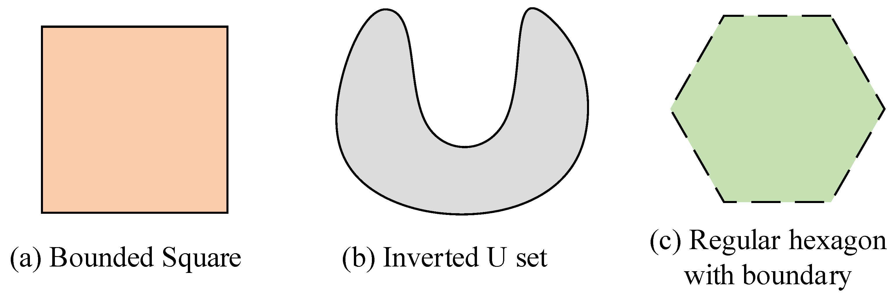
Figure 3 shows some typical convex and non-convex sets.
Figure 3a–c show the set of squares with boundaries, the regular U, and the regular hexagons with partial boundaries, respectively.
Figure 3a,c are non-convex sets, and
Figure 3b is CS. The following defines the CF of the COA. In function
, if
is a CS.
in the set satisfies
. The expression is shown in Formula (10).
In Formula (10),
represents a convex function. From a two-dimensional perspective, the inequality shown in Formula (10) can be regarded as the connection of two points,
and
, on a convex function. The line is on the curve formed by the convex function
. If
, Formula (10) is valid. In this case,
is strictly a CF. Assuming that CF
is differentiable, the CS of CF
is
. The CF
needs to satisfy the expression shown in Formula (11).
If Formula (11) satisfies any
, for the first order of the CF, the theorem is a necessary and sufficient condition. COA is a developed area of mathematics. The minimum and minimum of CF on the CS can be found using this optimization technique. This method can not only optimize the EMS but also optimize the capacity of the power battery. Three conditions must be satisfied to solve the problem by using COA. First, the objective must be a convex function when seeking the minimum optimization. When seeking the maximum optimization, the objective must be a concave function. Second, inequality constraints must be convex functions. The third condition is that the formula constraint must be affine. In the dynamic system model of an EV, most variables are not convex functions. To better use the COA to optimize variables, these variables are processed to fulfill the demands of convex optimization. To optimize the power battery capacity while optimizing the EMS of an EV, the battery proportion factor
is added in Formula (2). The scale factor is the optimization variable in the COA to obtain the optimal capacity of the power battery. The quantity of parallel power batteries affects the power battery capacity. The power battery’s overall quality is also impacted by the scale factor. Therefore, the calculation expression of vehicle mass is shown in Formula (12).
The efficiency of electric vehicle motors is a discrete value. Therefore, the formula describing the electric vehicle motor model is a non-convex function. To better utilize the COA of the motor model, the motor model is fitted to improve convexity. The assembled motor model is shown in
Figure 4.
The motor power in the fitted motor model is a quadratic function of torque. The quadratic function is constrained to be convex. The expression of the constrained motor power is shown in Formula (13).
In Formula (13),
,
, and
are coefficients of different dimensions. In the motor model, the motor torque, as well as speed, are also related to the threshold value. The specific relationship is shown in Formula (14).
In Formula (14),
is the minimum torque at speed
.
is the maximum torque at
speed. The power battery model proposed in the study is non-convex. Firstly, to optimize the power battery model, the OCV of the power battery should be approximated as a linear function. Formula (15) is the linear function expression.
Secondly, the dynamic equation for a power battery is also simplified because the current function is not convex. SOC is replaced by the battery energy
as the state variable for the optimization problem. At this time, Formula (16) illustrates the power battery’s dynamic equation.
Finally, the approximate expression for the loss of power is shown in Formula (17).
In Formula (17),
represents the average efficiency of the power battery. The energy E and PB of the power battery meet the constraint inequality shown in Formula (18).
The goal of FCEV EMS based on COA and power cell optimization is also to minimize the hydrogen consumption of the system. Formula (19) is the cost function of the optimization problem.
In Formula (19),
,
, and
are the coefficients used to fit the quadratic term, the primary term, and the constant term, respectively.
represents fitting the quadratic function. By calculating this formula, the minimum hydrogen consumption of the system can be obtained. In summary, the COA is used to enhance the parameters of the motor model and the power battery model, respectively.
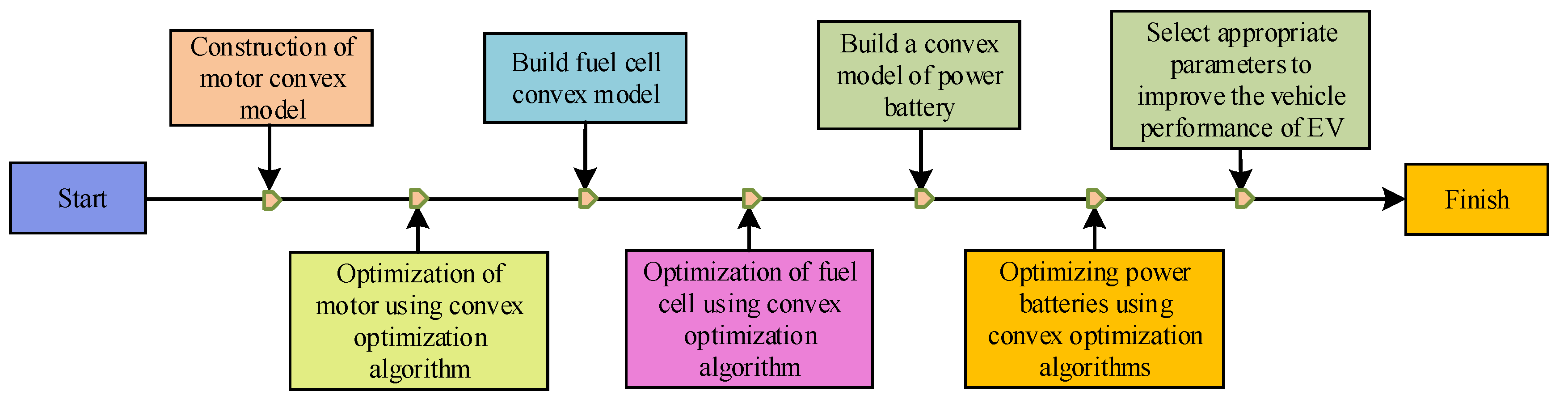
Figure 5 depicts the precise procedure.
From
Figure 5, the general process of using convex optimization algorithms for optimizing the performance of electric vehicles is as follows. Firstly, a convex model of the electric vehicle motor is constructed and the optimization model based on the convex optimization algorithm is established. Secondly, a convex model of the electric vehicle fuel cell is constructed and optimized through convex optimization algorithms. Then, a convex model of the electric vehicle power battery is constructed and optimized using convex optimization algorithms. Finally, appropriate parameters are selected to improve the vehicle performance of the electric vehicle.


