Article

Study on the Flow Behavior of Wellbore Fluids of a Natural Gas Hydrate Well with the Combined Depressurization and Heat Injection Method

1
School of Petroleum Engineering, China University of Petroleum, Beijing 102249, China
2
Research Institute of Petroleum Exploration & Development, PetroChina, Beijing 100083, China
3
Artificial Intelligence Technology R&D Center for Exploration and Development, CNPC, Beijing 100083, China
4
S1NOPEC Petroleum Exploration and Production Research Institute, Beijing 100083, China
5
COSL Middle EAST FZE (Iraq Branch), Amarah 62001, Iraq
*
Author to whom correspondence should be addressed.
Processes 2023, 11(6), 1625; https://doi.org/10.3390/pr11061625
Submission received: 19 April 2023 / Revised: 18 May 2023 / Accepted: 23 May 2023 / Published: 26 May 2023

Abstract

:
Natural gas hydrate (NGH) is a kind of clean energy with great potential because of its huge reserves. There are several effective methods for exploiting hydrate sediments such as depressurization, thermal excitation, inhibitor injection and displacement, etc. Among these methods, the combined depressurization and heat injection method is considered a very promising method, which solves the problem of insufficient heat supply during the depressurization process. In this paper, the mechanism of combined depressurization and heat injection exploitation of NGH is analyzed, and the multiphase flow models of the injection well and production well are established, respectively, for the parallel horizontal NGH well production system with this combined method. The multiphase flow laws of fluids in a wellbore were obtained, and the factors affecting the temperature and pressure distributions in the wellbore were analyzed. The results of this study show that gas and water are produced simultaneously in the process of exploitation with this combined depressurization and heat injection method. The electric submersible pump has a great influence on the flow of the fluids in the wellbore, and there are sudden skips of the temperature and pressure at the pump position. Increasing the depth and working frequency of the pump will reduce the risk of continuous discharge of water from the annulus. Increasing the injection rate and injection temperature can both improve the effect of heat injection. This study provides theoretical guidance for the combined extraction with depressurization and heat injection method and production optimization of NGH.

1. Introduction

Natural gas hydrate (NGH), commonly known as combustible ice, is an ice-like crystalline substance formed by natural gas and water under high pressure and low temperature conditions, which exists in marine deposits and permafrost [1]. As a kind of clean energy with huge reserves, it is very promising to become an alternative energy source for oil and natural gas in the future. NGH trials have been conducted in some places in the world with different exploitation methods, such as several production tests in the Mallik Methane Hydrate Deposits in Canada with depressurization and thermal stimulation methods [2], the CO2-CH4 displacement test at Alaska North Slope in America [3], two NGH production trials in Nankai Trough offshore of Japan with the depressurization method [4,5], the offshore production test in Shenhu area with the depressurization method [6], and the solid fluidization exploitation test in Liwan filed in the South China Sea [7], etc. The two NGH production trials in Nankai Trough offshore of Japan [4,5] and the trial practice in the Shenhu area of China [6] have proved that depressurization is an effective gas hydrate exploitation method. However, there are still some problems such as low thermal conductivity and insufficient heat supply to the formation with this single depressurization method, reducing the hydrate decomposition rate and the effectiveness of NGH extraction. In contrast, the combined depressurization and heat injection method can solve the core problem of insufficient heat supply in the depressurization exploitation process by injecting hot fluid and can promote more efficient extraction of NGH. During the process of exploitation of NGH with the combined depressurization and heat injection method, the flow behavior of wellbore fluids is complicated and can influence the effect of the combined exploitation of NGH. Therefore, it is necessary to clarify the fluid flow laws in the wellbore to improve the heat injection effect of NGH exploitation and optimize production parameters.
Current studies on the flow behavior of wellbore fluids in NGH production wells with the combined depressurization and heat injection method have mainly focused on laboratory experiments and numerical simulations at the reservoir level. Konno et al. conducted several gas production tests at various depressurization schemes and drew the conclusion that appropriate heat of hydrate bearing is a key factor for dissociating hydrate [8]. Li et al. used a pressure vessel to compare the dynamics of a dual horizontal well system with different well placement styles induced by steam injection [9]. Jin et al. developed experimental techniques to determine the hydrate dissociation front by combining depressurization and hot brine stimulation and numerical techniques to confirm that the combined method with depressurization and thermal stimulation can yield more gas than depressurization alone [10]. Zhao et al. employed numerical simulation to prove that a single vertical well with the depressurization method is less effective for gas hydrate in Qilian Mountain permafrost and suggested a horizontal well design or the combination of depressurization and thermal stimulation for hydrate gas production [11]. Moridis et al. used TOUGH+HYDRATE software to simulate the dynamics of the single-well design for simultaneous heat addition for a gas production system and the two-well design for a gas production system with hot water injection [12]. Many experiments were performed to study the multiphase flow in oil and gas production wells [13,14,15,16]. Hasan et al. built the model for computing the countercurrent flow of heat in tubing and annulus systems [17]. Several scholars analyzed the multiphase flow during the drilling of NGH reservoirs [18,19,20]. Ping et al. established the wellbore flow model of ESP-lifted depressurized NGH production wells with dedicated gas/water lines and a mixing-delivery line [21].
However, there are relatively few studies on the flow behavior of the fluids in a wellbore during NGH exploitation with the combined depressurization and heat injection method reported in the published literature. The flow behavior of fluids in the wellbore is complicated and can influence the effect of NGH exploitation. Therefore, it is necessary to establish the multiphase flow models of the injection well and production well for the NGH well production system with this combined method and analyze their flow laws to find out the factors affecting the effect of heat injection and carry out the optimization of hydrate production.
In this paper, the multiphase flow models of the injection well and production well were established, respectively, for the parallel horizontal NGH well production system, considering the heat source superposition theory and the heat change caused by hydrate dissociation and Joule–Thomson effect in the temperature calculation model. The finite difference iterative method was applied to solve the mathematical multiphase flow model of the NGH well with the combined depressurization and heat injection method. The purpose of this research is to figure out the flow laws of wellbore fluid of the NGH well with the combined depressurization and heat injection method and to analyze the influencing factors of temperature and pressure distributions in the production well and injection well to optimize the production of NGH wells and injection parameters. The objectives of this paper are to optimize the pump depth and frequency to reduce the risk of continuous water outflow from the annulus of the production well and to improve the injection effect. This study lays the foundation for combined extraction with the depressurization and heat injection method and production optimization of NGH wells.
This paper is organized as follows. The mechanism of the combined depressurization and heat injection method of NGH exploitation is investigated in Section 2. The multiphase flow models of the parallel horizontal NGH well production system with this combined method are developed separately in Section 3. The models were solved, and their applications are analyzed and discussed in Section 4.

2. Mechanism Study

2.1. Mechanism of Combined Depressurization and Heat Injection Method of NGH Exploitation

The depressurization exploitation method controls the dissociation of hydrate by changing the pressure in the reservoir, which is easy to operate and suitable for the development of hydrate reservoirs where an underlay free gas zone exists. However, this method becomes less effective when there is no free gas in the lower part of the hydrate reservoir. In addition, this method is limited by two key factors, which are reservoir permeability and heat supply, and may even cause formation sand failure and formation instability during the depressurization exploitation process. In order to avoid problems such as reduced gas production capacity caused by the change in formation conditions at the late stage of hydrate development and insufficient energy due to the decrease in formation temperature and hydrate reformation near the bottom of the wellbore, it is necessary to supplement enough heat to the reservoir. The heat injection method is performed by injecting hot fluid into the reservoir, which has little impact on the environment. However, due to heat loss in the transfer process, the heat injection method is rarely used alone and is generally used as an auxiliary means in conjunction with other exploitation methods. The combined depressurization and heat injection method integrates the advantages of the depressurization method and the thermal stimulation method to make up for the shortcomings of the single depressurization method or the thermal stimulation method, with depressurization as the main method and heat injection as the auxiliary method.
For deep sea environments, the temperature of seawater gradually decreases with the increase in depth when the water depth is greater than 200 m. The section from the thermocline to the seafloor is the constant temperature layer, with a temperature range of 2–6 °C. Influenced by the heat transfer between the seawater and wellbore, the heat loss in the wellbore section is great when exploiting gas hydrate in the sea area using the heat injection method, and the thermal fluid injected into the reservoir cannot play the role of heating effectively, so the insulated casing is needed to solve the problem of wellbore insulation. Therefore, the combined depressurization and heat injection method is suitable for onshore NGH exploitation in the permafrost zone. The NGH production test of the 5L-38 well was conducted successfully with 470 m3 gas production accomplished in Canada using the combined depressurization method and hot water circulation method [2], verifying the feasibility of the combined exploitation method with depressurization and heat injection.

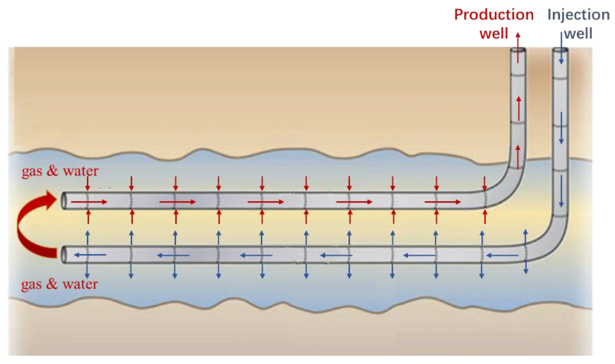
2.2. Mechanism of Parallel Horizontal Wells in NGH Reservoirs

Several research results have shown that the parallel horizontal NGH well production system with the combined depressurization and heat injection method is more effective than exploitation with single horizontal wells or vertical wells [9,11,12,22]. According to the different methods of well placement, the dual horizontal well production system for the combined exploitation of the NGH reservoir with the depressurization and heat injection method can be divided into two types. One is that the production well is located in the upper part of the injection well (Figure 1); the other is that the production well is located in the lower part of the injection well, similar to SAGD (steam-assisted gravity drainage). After hot water is injected into the injection well, heat is released to stimulate the gas hydrate reservoir, which dissociates into gas and water flowing into the production well together, as shown in Figure 1. During the production process, the pressure of the system slowly decreases, which further promotes the dissociation of gas hydrates. Due to the low density of natural gas, it will migrate upward, and water will migrate downward; therefore, a dual horizontal NGH well production system with the injection well located in the lower part of the production well can produce more natural gas and less water than a dual horizontal well production system with the injection well located in the upper part of the production well.

3. Model Assumptions and Establishment

Based on the model assumptions of a designed parallel horizontal NGH well production system lifted by a flexible electrical submersible pump (ESP) with the combined depressurization and heat injection method, the multiphase flow models of the injection well and production well were established, respectively.

3.1. Model Assumptions

The hot water injection well is located in the lower part of the production well in the parallel horizontal NGH well production system with the combined depressurization and heat injection method. As shown in Figure 2 and Figure 3, the horizontal section of the hot water injection well and production well are completed using screens. Hot water is injected through the toe and screen of the injected well into the surrounding reservoir, and then it decomposes into gas and water under the effect of thermal stimulation. The decomposed gas and water and the injected hot water enter the wellbore through the toe and screen of the production well, ignoring the effect of solid particles of NGH on the multiphase flow in the wellbore. In order to meet the requirements of gas hydrate drainage and dogleg degree of the horizontal well, a flexible ESP is used to lift the gas and water in the NGH well, as shown in Figure 3. ESP can draw water from the formation and well to lower the water level and decompose the gas hydrate by depressurization, while the hot water injection well can supplement heat formation to promote the dissociation of the hydrate reservoir. After the combined extraction of NGH, the decomposed natural gas, water, and part of the injected hot water flow from the bottom of the well to the entrance of the ESP with gas and water produced together. When flowing through the separator of ESP assembly, gas and water are separated, and the gas enters the annulus and then flows upward to the wellhead, while the water enters the tubing after being pressurized by the pump and finally flows toward the wellhead.

3.2. Mass Balance Equation

Considering the structure of the pipe and the flow process of the fluid inside the wellbore, the mass balance equations of single-phase flow for the hot water injection well and gas–liquid two-phase flow for the NGH production well are established, respectively.
For hot water injection wells, the injected water in the tubing flows downward, which can be considered a single-phase flow. According to the principle of mass conservation, the mass balance equation for the hot water injection well is shown in Equation (1).
ρ w i t + ( ρ w i ν w i ) z = 0 ;
For the dual horizontal NGH well production system with the depressurization and heat injection method, the injected water is drained back through the wellbore, and natural gas and water decomposed from the gas hydrate reservoir also flow into the wellbore. According to the principle of mass conservation, the equation of continuity of the gas phase in the NGH production well is shown in Equation (2).
( ρ g E g ) t + ( ρ g E g ν g ) z = q g ;
The mass balance equation of the liquid phase in the NGH production well is shown in Equation (3).
( ρ l E l ) t + ( ρ l E l ν l ) z = q w p ;
where:
E g + E l = 1 ;

3.3. Momentum Conservation Equation

Based on the mass balance equation and the law of conservation of momentum, the wellbore pressure drop model for a hot water injection well can be obtained, as shown in Equation (5).
d P i d z = ( ρ w i ν w i ) t + ( ρ w i ν w i 2 ) z g ρ w i cos θ + 2 f r ρ w i ν w i 2 d i ;
The pressure drop of the gas–liquid mixture in the NGH production well can be expressed by Equation (6).
d P p d z = ( ρ m ν m ) t + ( ρ m ν m 2 ) z + g ρ m cos θ + 2 f r ρ m ν m 2 d p ;
The increased pressure generated by ESP at the location of the pump needs to be taken into account in the pressure drop model.
Chen relation is used to calculate the friction factor of the pipe, due to its good adaptability to different Re and ε / D [23].
1 f r = 2.0 log [ ε 3.7065 D 5.0452 Re log ( 1 2.8257 ( ε D ) 1.1098 + 5.8506 Re 0.8981 ) ] ;

3.4. Energy Conservation Equation

The processes of formation heat transfer in the vertical and inclined well segment include convective heat transfer inside the tubing, heat conduction of tubing surface, radiation heat transfer between the tubing and annulus, heat conduction of casing surface, heat conduction of cement sheath, and non-stationary heat transfer in the formation section. The Willhite model was used to calculate wellbore heat loss between tubing fluid and formation [24,25], as shown in Equation (8). The temperature increase caused by the pump and motor needs to be considered at the location of ESP.
d Q d z = 2 π r to U to k e k e + r to U to T D ( T f T e ) ;
Here, the overall heat transfer coefficient between the wellbore and the formation is expressed by Equation (9).
1 U to = r to r ti h t + r to ln ( r to / r ti ) k t + 1 ( h c + h r ) + r to ln ( r co / r ci ) k cas + r to ln ( r cf / r co ) k cem ;
The process of formation heat transfer in the horizontal well segment includes convective heat transfer of fluid inside the screen, heat conduction of the screen surface, and non-stationary heat transfer in the formation section. The interaction effect of temperature changes between the upper and lower horizontal wells needs to be considered when calculating the heat loss of the horizontal well section. According to the heat source superposition theory [26] and the heat change caused by hydrate dissociation and Joule–Thomson effect, the temperature distribution models at different positions in the horizontal section of injection and production wells in the exploitation process of NGH with the combined depressurization and heat injection method can be written as:
T T 0 = d Q 1 / d z 4 π k 1 E i ( r 2 4 λ α 1 t 1 ) d Q 2 / d z 4 π k 2 E i ( r 2 4 λ α 2 t 2 ) + d Q H c p ;

3.5. Auxiliary Equation

The physical properties of natural gas along the wellbore were calculated using the Peng–Robinson equation of state [24], such as density, fugacity, Z-Factor, etc.
According to the Kim–Bishnoi model, the rate of hydrate dissociation is proportional to the total surface area of the particles and the driving force. Combined with the Arrhenius equation [27], the equation of gas hydrate dissociation rate can be obtained in the following expression:
r h = k c A i exp ( Δ E R T ) ( P e q P ) ;
The dissociation process of hydrates is endothermic, which leads to a continuous decrease in reservoir temperature. It is negative when the hydrate decomposes and positive when it generates. The heat generated by the dissociation of hydrates can be obtained using the Clausius–Clapeyron equation [28].
Δ H = Z R d ln ( p ) d ( 1 / T ) ;

4. Results and Discussion

4.1. Main Parameters for Simulation

The physical parameters of the reservoir are derived from the Muli mineral district in Qilian Mountain permafrost in Qinghai Province. Fracture-filling and pore-filling are the two main types of gas hydrate present in this area, and the lithologies of the reservoir are mainly siltstone, oil shale, mudstone, and fine sandstone, with a small amount of medium-grained sandstone. The permafrost layer is 160 m thick, and the average surface temperature is −2 °C. The gas hydrate stability zone is 107 m thick with an average temperature of about 12 °C. The NGH production system is constructed with two horizontal wells, with an injection well positioned 10 m above the production well. The same string type is used for well injection and production, and the lifting technique is a flexible ESP with a designed pump depth of 450 m. The basic parameters for the injection well and the production well are listed in Table 1, and the other main parameters of the model are shown in Table 2.

4.2. Analysis of Multiphase Flow Law in Wellbore

The mathematical multiphase flow model of the NGH well with the combined depressurization and heat injection method is composed of Equations (1)–(12). The finite-difference method was adopted to solve the iterative problem, and the flowchart for computing these models is presented in Figure 4. Distribution curves of the wellbore pressure and temperature of the injection well and production well and the gas volume fraction of the production well can be obtained (Figure 5, Figure 6 and Figure 7). The calculation results show that the flow of the hot water injected into the wellbore is a single-phase flow, and the flow in the NGH production well is a gas–liquid two-phase flow. The pressure and temperature drop faster in the vertical wellbore section and change little in the horizontal wellbore section of the injection well and the NGH production well, as shown in Figure 5 and Figure 6. This is because there is no gravity effect on the horizontal section in this model, and the ambient temperature field around the reservoir changes little. The flow pattern from the bottom of the well to the entrance of the pump is slug flow with insignificant change in gas volume fraction. The flow pattern of the fluid from the pump discharge to the wellhead section is bubble flow. Due to the separation effect of the gas separator and the pressurization effect of the pump, the gas volume fraction in the tubing at the ESP discharge location decreases sharply and gradually increases during the flow to the wellhead, as shown in Figure 7. However, the gas volume fraction in the annulus increases suddenly at the pump discharge location and gradually increases during the upward flow to the dynamic liquid level. The flow law of the fluid in the annulus is affected by the wellhead casing pressure. Increasing the wellhead casing pressure and lowering the dynamic fluid level can reduce the risk of continuous water discharge from the annulus of the NGH production well.

4.3. Analysis of the Influence of Temperature and Pressure Distributions in the Injection Well

Parameter sensitivity analysis and optimization of injection parameters were performed using the wellbore multiphase flow calculation model. The analysis results show that the increase in injection rate has a greater impact on the wellbore temperature distribution, followed by the increase in injection temperature, as shown in Figure 8 and Figure 9, while the increase in injection pressure has no impact on the wellbore temperature distribution. The increase in injection rate and injection pressure has no effect on the wellbore pressure distribution of the injection well, while the increase in injection pressure will affect the wellbore pressure distribution of the injection well (Figure 10). Therefore, increasing the injection rate and injection temperature can both improve the heat injection effect, among which increasing the injection rate has a better heat injection effect.

4.4. Analysis of the Influence of Pressure Distributions in the Production Well

The flexible ESP is used to lift NGH in the process of combined exploitation with the depressurization and heat injection method. In the process of gas drainage recovery with ESP technology, gas and water are produced together. ESP has a great influence on the flow law of the fluid in the NGH production well, and sudden changes in temperature and pressure occur at the location of the pump (Figure 5, Figure 6, Figure 11 and Figure 12). When the pump depth increases, the flow pressure at the bottom of the well decreases and the dynamic fluid level drops, thus reducing the risk of water discharge from the annulus, as shown in Figure 11. As the pump frequency increases, the flowing pressure at the bottom of the well decreases, resulting in an increase in water production from the tubing and a decrease in the dynamic fluid level in the annulus, thereby reducing the risk of continuous water outflow from the annulus, as illustrated in Figure 12.

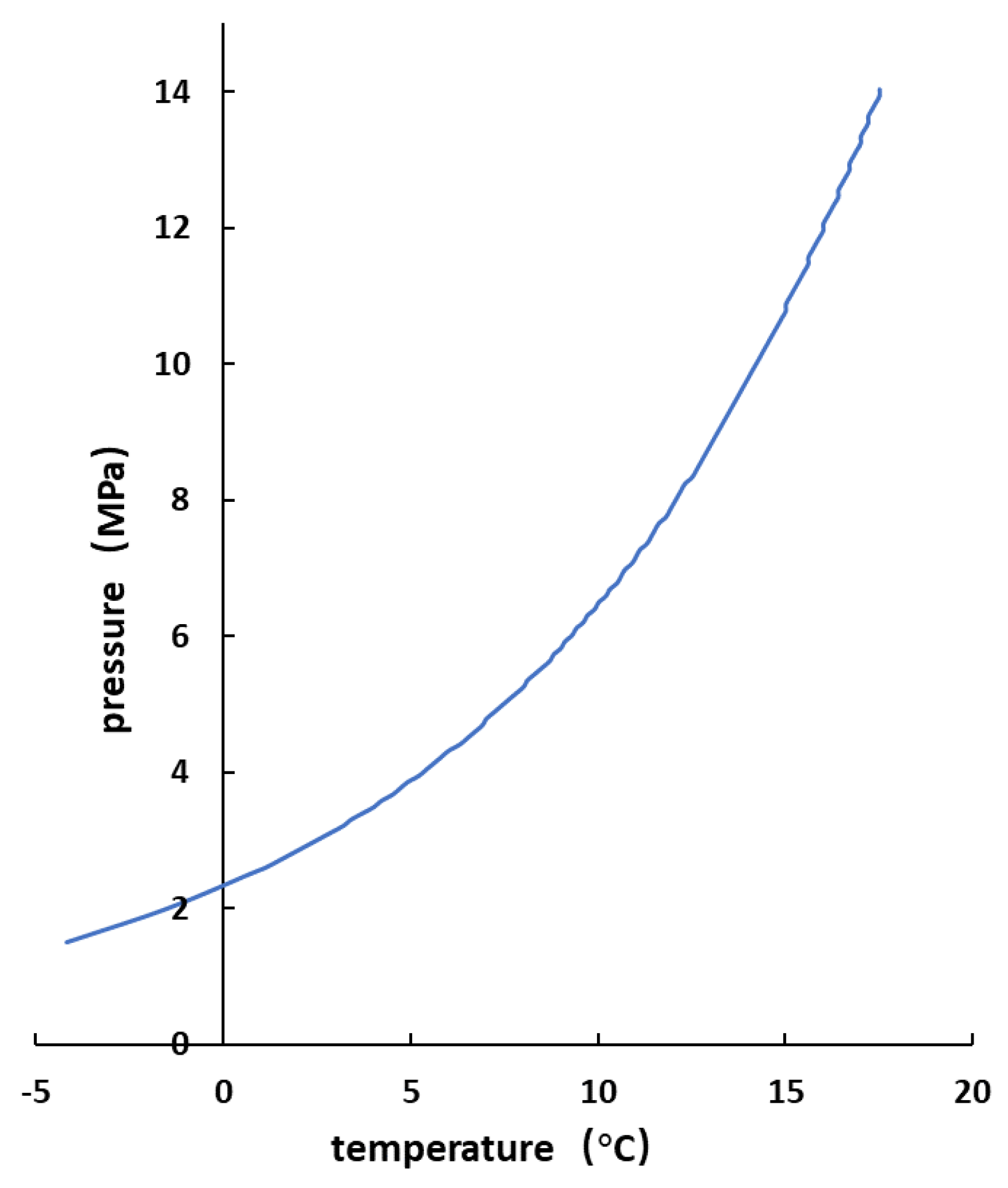
4.5. Risk Analysis of Hydrate Reformation in the Wellbore

According to the Chen–Guo phase equilibrium prediction model, hydrate formation conditions can be predicted with an equation of state to calculate the fugacity of the components for NGH [29], as shown in Figure 13. According to the pressure distribution of the wellbore, the corresponding equilibrium temperature can be calculated and compared with the predicted temperature distribution of the wellbore based on the multiphase flow models. The calculation results show that the risk of hydrate reformation is highest at the pump discharge outlet (Figure 14), which is mainly due to the increase in the phase equilibrium temperature at the pump outlet caused by the pressurization effect of the pump.

5. Conclusions

(1)
The combined depressurization and heat injection method is suitable for onshore NGH exploitation in the permafrost zone. The dual horizontal NGH production system with the combined depressurization and heat injection method can produce more gas and less water than the production system with the injection well below the production well and with the injection well above the production well due to gravity.
(2)
Gas and liquid are extracted together in the production well in the process of combined depressurization and heat injection exploitation of NGH. ESP has a great influence on the flow law of the fluids in the production well, and temperature and pressure change abruptly at the position of ESP. Increasing the casing pressure of the wellhead, pump depth, and ESP working frequency can reduce the risk of continuous water production in the annulus in the production well.
(3)
Increasing the injection rate and injection temperature can both improve the heat injection effect, while increasing the injection rate has a better heat injection effect.
(4)
The risk of hydrate reformation in the pump discharge is the greatest in the wellbore due to the pressurization effect of the pump.

Author Contributions

X.P.: conceptualization, writing—original draft; G.H.: supervision; J.Z.: methodology, data curation; J.C.: coding; X.C.: validation, writing—review and editing; H.T.: resources, investigation. All authors have read and agreed to the published version of the manuscript.

Funding

This research was funded by Sinopec Outstanding Youth Program Project (P20025) and Major Fund Project of Southern Marine Science and Engineering Guangdong Laboratory (GML2019ZD0102). And the APC was funded by Research Institute of Petroleum Exploration & Development, PetroChina.

Institutional Review Board Statement

Not applicable.

Informed Consent Statement

Not applicable.

Data Availability Statement

Not applicable.

Acknowledgments

The authors would like to express their appreciation to the Sinopec Outstanding Youth Program Project for “Exploration of the prediction method and effective development mode of natural gas hydrate production deliverability” (P20025) and the Major Fund Project of Southern Marine Science and Engineering Guangdong Laboratory for “Research on accumulation mechanism of gas hydrate system in Qiongdongnan Basin” (GML2019ZD0102).

Conflicts of Interest

The authors declare no conflict of interest.

Nomenclature

ρ w i The density of the injected water, kg/m3;
ν w i The velocity of the injected water, m/s;
t Time, s;
ρ l The density of the water produced by the dissociation of the hydrate reservoir into the production well, kg/m3;
ρ g The density of the gas produced by the dissociation of the hydrate reservoir into the production well, kg/m3;
E l Liquid holdup in the production well, dimensionless;
E g Gas holdup in the production well, dimensionless;
ν l Liquid velocity in the production well, m/s;
ν g Gas velocity in the production well, m/s;
q g Mass flow rate of the gas decomposed from the hydrate reservoir per unit volume, kg/(m3·s);
q w p Mass flow rate of the water decomposed from the hydrate reservoir per unit volume, kg/(m3·s);
P i Pressure of the fluid in the injection well, MPa;
P p Pressure of the fluid in the production well, MPa;
ρ m Density of the mixed fluid in the production well, kg/m3;
ν m Velocity of the mixed fluid in the production well, m/s;
f r Fanning friction factor, dimensionless;
d i Inside diameter of the injection well, m;
d p Inside diameter of the production well, m;
D Diameter of the wellbore, m;
ε Roughness of the wall, m;
Re Reynolds number, dimensionless;
d Q / d z Heat transfer rate, J/m;
U to Overall heat transfer coefficient, J/m;
r to Tubing outside diameter of the injection and production wells, m;
r ti Tubing inside diameter of the injection and production wells, m;
r co Casing outside diameter of the injection and production wells, m;
r ci Casing inside diameter of the injection and production wells, m;
r cf Cement sheath outside diameter of the injection and production wells, m;
h t Forced-convection heat transfer coefficient for the tubing fluid, W/(m2·K);
h c Convective heat transfer coefficient for annulus fluid, W/(m2·K);
h r Radiative heat transfer coefficient for the annulus, W/(m2·K);
k t Tubing thermal conductivity, W/(m·K);
k cas Casing thermal conductivity, W/(m·K);
k cem Cement thermal conductivity, W/(m·K);
d Q 1 / d z Heat loss rate of the horizontal section of the injection well, J/m;
d Q 2 / d z Heat loss rate of the horizontal section of the production well, J/m;
k 1 Thermal conductivity of the rock matrix around the injection well, W/(m·K);
k 2 Thermal conductivity of the rock matrix around the production well, W/(m·K);
α 1 Thermal diffusion coefficient of the rock matrix around the injection well, m2/s;
α 2 Thermal diffusion coefficient of the rock matrix around the production well, m2/s;
t 1 Heat injection time, day;
t 2 Heat injection time, day;
Q H Heat changes caused by the decomposition of natural gas hydrates and Joule–Thomson effect, J;
c p Heat capacity at constant pressure, J/K;
r h Decomposition rate of hydrates, m3/min;
k c Decomposition rate constant of hydrates, k c = 1.24 × 10¹¹ mol/(m2·MPa·s);
A i Total surface area of hydrate particles, m2;
Δ E Activation energy, Δ E = 78.3 kJ/mol;
R Ideal gas constant, R = 8.314 J/(mol·K);
T Temperature, K;
P e q Pressure under phase equilibrium conditions, MPa;
P Pressure, MPa;
Δ H Dissociation enthalpies of hydrates, J/mol.
Abbreviations and symbols
NGHNatural gas hydrate;
ESPElectric submersible pump;
SAGDSteam assisted gravity drainage.

References

  1. Janicki, G.; Schlüter, S.; Hennig, T.; Deerberg, G. Simulation of Subsea Gas Hydrate Exploitation. Energy Procedia 2014, 59, 82–89. [Google Scholar] [CrossRef]
  2. Kurihara, M.; Sato, A.; Funatsu, K.; Ouchi, H.; Ashford, D. Analysis of Production Data for 2007/2008 Mallik Gas Hydrate Production Tests in Canada. In Proceedings of the International Oil and Gas Conference and Exhibition in China, Beijing, China, 8–10 June 2010. [Google Scholar]
  3. Birkedal, K.A.; Hauge, L.P.; Graue, A.; Ersland, G. Transport Mechanisms for CO2-CH4 Exchange and Safe CO2 Storage in Hydrate-Bearing Sandstone. Energies 2015, 8, 4073–4095. [Google Scholar] [CrossRef]
  4. Sakurai, S.; Nishioka, I.; Matsuzawa, M.; Matzain, B.; Goto, A.; Lee, J.E. Issues and Challenges with Controlling Large Drawdown in the First Offshore Methane-Hydrate Production Test. SPE Prod. Oper. 2017, 32, 500–516. [Google Scholar] [CrossRef]
  5. Yamamoto, K.; Wang, X.-X.; Tamaki, M.; Suzuki, K. The second offshore production of methane hydrate in the Nankai trough and gas production behavior from a heterogeneous methane hydrate reservoir. RSC Adv. 2019, 9, 25987–26013. [Google Scholar] [CrossRef]
  6. Li, J.F.; Ye, J.L.; Qin, X.W.; Qiu, H.J.; Wu, N.Y.; Lu, H.L.; Xie, W.W.; Lu, J.A.; Peng, F.; Xu, Z.Q. The first offshore natural gas hydrate production test in South China Sea. China Geol. 2018, 1, 5–16. [Google Scholar] [CrossRef]
  7. Wei, N.; Zhao, J.; Sun, W.; Zhou, S.; Zhang, L.; Li, Q.; Fu, Q.; Lü, X.; Zheng, L. Non-equilibrium multiphase wellbore flow characteristics in solid fluidization exploitation of marine gas hydrate reservoirs. Nat. Gas Ind. B 2019, 6, 282–292. [Google Scholar] [CrossRef]
  8. Konno, Y.; Jin, Y.; Shinjou, K.; Nagao, J. Experimental evaluation of the gas recovery factor of methane hydrate in sandy sediment. RSC Adv. 2014, 4, 51666–51675. [Google Scholar] [CrossRef]
  9. Li, G.; Li, X.-S.; Yang, B.; Duan, L.-P.; Huang, N.-S.; Zhang, Y.; Tang, L.-G. The use of dual horizontal wells in gas production from hydrate accumulations. Appl. Energy 2013, 112, 1303–1310. [Google Scholar] [CrossRef]
  10. Jin, Y.; Li, S.; Yang, D.; Jiang, X. Determination of dissociation front and operational optimization for hydrate development by combining depressurization and hot brine stimulation. J. Nat. Gas Sci. Eng. 2018, 50, 215–230. [Google Scholar] [CrossRef]
  11. Zhao, J.; Yu, T.; Song, Y.; Liu, D.; Liu, W.; Liu, Y.; Yang, M.; Ruan, X.; Li, Y. Numerical simulation of gas production from hydrate deposits using a single vertical well by depressurization in the Qilian Mountain permafrost, Qinghai-Tibet Plateau, China. Energy 2013, 52, 308–319. [Google Scholar] [CrossRef]
  12. Moridis, G.J.; Reagan, M.T.; Boyle, K.L.; Zhang, K. Evaluation of the Gas Production Potential of Some Particularly Challenging Types of Oceanic Hydrate Deposits. Transp. Porous Media 2011, 90, 269–299. [Google Scholar] [CrossRef]
  13. Ros, N.C.J. Simultaneous Flow of Gas and Liquid As Encountered in Well Tubing. J. Pet. Technol. 1961, 13, 1037–1049. [Google Scholar] [CrossRef]
  14. Duns, H., Jr.; Ros, N.C.J. Vertical flow of gas and liquid mixtures in wells. In Proceedings of the 6th World Petroleum Congress, Frankfurt am Main, Germany, 19–26 June 1963; pp. 451–465. [Google Scholar]
  15. Hagedorn, A.R.; Brown, K.E. Experimental Study of Pressure Gradients Occurring during Continuous Two-Phase Flow in Small-Diameter Vertical Conduits. J. Pet. Technol. 1965, 17, 475–484. [Google Scholar] [CrossRef]
  16. Orkiszewski, J. Predicting Two-Phase Pressure Drops in Vertical Pipes. J. Pet. Technol. 1967, 19, 829–838. [Google Scholar] [CrossRef]
  17. Hasan, A.R.; Jang, M. An analytic model for computing the countercurrent flow of heat in tubing and annulus system and its application: Jet pump. J. Pet. Sci. Eng. 2021, 203, 108492. [Google Scholar] [CrossRef]
  18. Wei, N.; Sun, W.; Meng, Y.; Zhou, S.; Li, G.; Guo, P.; Dong, K.; Li, Q. Sensitivity analysis of multiphase flow in annulus during drilling of marine natural gas hydrate reservoirs. J. Nat. Gas Sci. Eng. 2016, 36, 692–707. [Google Scholar] [CrossRef]
  19. Sun, B.; Gao, Y.; Wang, Z.; Li, H. Temperature Calculation and Prediction of Gas Hydrates Formed Region in Wellbore in Deepwater Drilling. In Proceedings of the ISOPE-2008, International Offshore and Polar Engineering Conference, Vancouver, BC, Canada, 6–11 July 2008. [Google Scholar]
  20. Liao, Y.; Sun, X.; Sun, B.; Gao, Y.; Wang, Z. Transient gas-liquid-solid flow model with heat and mass transfer for hydrate reservoir drilling. Int. J. Heat Mass Transf. 2019, 141, 476–486. [Google Scholar] [CrossRef]
  21. Ping, X.; Han, G.; Cen, X.; Bai, Z.; Zhu, W.; Peng, L.; Ma, B. Prediction of Pressure and Temperature Profiles and Hydrate Formation Region in ESP-Lifted Natural Gas Hydrate Wells. In Proceedings of the SPE Western Regional Meeting, Bakersfield, CA, USA, 26–28 April 2022. [Google Scholar]
  22. Yang, S.; Lang, X.; Wang, Y.; Wen, Y.; Fan, S. Numerical simulation of Class 3 hydrate reservoirs exploiting using horizontal well by depressurization and thermal co-stimulation. Energy Convers. Manag. 2014, 77, 298–305. [Google Scholar] [CrossRef]
  23. Ning, H.C. An Explicit Equation for Friction Factor in Pipe. Ind. Eng. Chem. Fundam. 1979, 18, 296–297. [Google Scholar]
  24. Bhawangirkar, D.R.; Adhikari, J.; Sangwai, J.S. Thermodynamic modeling of phase equilibria of clathrate hydrates formed from CH4, CO2, C2H6, N2 and C3H8, with different equations of state. J. Chem. Thermodyn. 2018, 117, 180–192. [Google Scholar] [CrossRef]
  25. Aspects of wellbore heat transfer during two-phase flow. Int. J. Rock Mech. Min. Sci. Geomech. Abstr. 1995, 32, A20. [CrossRef]
  26. Duong, A.N.; Tomberlin, T.A.; Cyrot, M. A New Analytical Model for Conduction Heating during the SAGD Circulation Phase. In Proceedings of the International Thermal Operations and Heavy Oil Symposium, Calgary, AB, Canada, 20–23 October 2008. [Google Scholar]
  27. Kim, H.C.; Bishnoi, P.R.; Heidemann, R.A.; Rizvi, S. Kinetics of methane hydrate decomposition. Chem. Eng. Sci. 1987, 42, 1645–1653. [Google Scholar] [CrossRef]
  28. Sun, S.; Gu, L.; Yang, Z.; Lin, H.; Li, Y. Thermophysical properties of natural gas hydrates: A review—ScienceDirect. Nat. Gas Ind. B 2022, 9, 246–263. [Google Scholar] [CrossRef]
  29. Chen, G.-J.; Guo, T.-M. A new approach to gas hydrate modelling. Chem. Eng. J. 1998, 71, 145–151. [Google Scholar] [CrossRef]
Figure 1. Schematic diagram of parallel horizontal NGH well production system with the combined depressurization and heat injection method.
Processes 11 01625 g001
Figure 2. Wellbore sketch for hot water injection well.
Processes 11 01625 g002
Figure 3. Wellbore sketch for ESP-lifted NGH production well.
Processes 11 01625 g003
Figure 4. Flowchart for computing the parallel horizontal NGH well production system with the combined depressurization and heat injection method.
Processes 11 01625 g004
Figure 5. Pressure distributions of wellbore.
Processes 11 01625 g005
Figure 6. Temperature distributions of wellbore.
Processes 11 01625 g006
Figure 7. Gas volume fraction distribution in the ESP-lifted NGH production well.
Processes 11 01625 g007
Figure 8. Effect of injection rate on tubing temperature distribution in injection well.
Processes 11 01625 g008
Figure 9. Effect of injection temperature on tubing temperature distribution in injection well.
Processes 11 01625 g009
Figure 10. Effect of injection pressure on tubing pressure distribution in injection well.
Processes 11 01625 g010
Figure 11. Effect of pump depth on pressure distribution in production well.
Processes 11 01625 g011
Figure 12. Effect of frequency on pressure distribution in production well.
Processes 11 01625 g012
Figure 13. Phase equilibrium curve of NGH.
Processes 11 01625 g013
Figure 14. NGH reformation risk of production wellbore.
Processes 11 01625 g014
Table 1. Basic parameters for the injection well and the production well.
Well TypeMeasured Depth of Point A (m)Vertical Depth of Point A (m)Horizontal Section Length (m)Casing Size
(mm)
Tubing Size
(mm)
Screen Size
(mm)
Injection well550440400244.573177.8
Production well530430400244.573177.8
Table 2. Main parameters for simulation.
ParameterValueParameterValue
Thickness of reservoir (m)160Porosity of reservoir0.35
Permeability of reservoir (md)0.068Surface temperature (°C)−2
Rock density (kg/m3)2650Initial saturation of water0.3
Initial pressure of reservoir (MPa)5.1Initial saturation of hydrate0.68
Earth thermal conductivity (W/m/K)2.1Gas flow rate (m3/d)20,000
Tubing thermal conductivity (W/m/K)40Water flow rate (m3/d)100
Casing thermal conductivity (W/m/K)40Surface injection rate (m3/d)100
Cement thermal conductivity (W/m/K)1.1Gas-specific gravity0.65
Geothermal gradient (°C/100m)3.2Depth of production well (m)920
Bottom-hole temperature (°C)12Depth of injection well (m)938
Surface injection temperature (°C)60Injection pressure (MPa)3
Gas–water separation efficiency0.95Depth of ESP (m)450
Flowing pressure at bottom (MPa)3ESP frequency (HZ)55
Disclaimer/Publisher’s Note: The statements, opinions and data contained in all publications are solely those of the individual author(s) and contributor(s) and not of MDPI and/or the editor(s). MDPI and/or the editor(s) disclaim responsibility for any injury to people or property resulting from any ideas, methods, instructions or products referred to in the content.

