Abstract
A microchannel heat exchanger effectively evacuates heat from a confined space. This paper attempts to gain insight into the combinatorial repercussions of simultaneously coupling two factors that affect a microchannel’s performance, of which channel size and micro-insert complexity are the two main contributors. With water as the working fluid, an ANSYS-based numerical analysis was carried out for two distinct channel sizes, 1 and 2 mm, both with and without micro-inserts. The Reynolds numbers varied between 125 and 4992 and between 250 and 9985 for the 1 and 2 mm channels, respectively. For the 2 mm diameter channel, adding micro-inserts raised the overall pressure drop with increased Reynolds number. The inclusion of micro-inserts increased the pressure drop in the 1 mm channel at first, and thereafter the pressure drop decreased. Incorporating micro-inserts into the channel resulted in enhanced heat transfer. The trade-off between enhanced heat transfer performance and a larger pressure drop was calculated by evaluating the channel’s overall performance using the thermal performance factor. Micro-inserts were found to be most useful for improving overall performance in the low-to-moderate Reynolds number range, and their effectiveness increased with decreasing channel size. Changing the channel diameter and structure of the design can improve heat transmission through microchannels.
1. Introduction
The swift growth of tiny and extremely heat-dense, modern, specialized equipment brought to light the compelling necessity for small-scale thermal management systems. The problem of removing rising heat production densities [1] with falling equipment dimensions [2] has generated a lot of interest in fluid flow in microchannels. The ground-breaking work of Tuckerman and Pease (1981) [3] addressing the issue of removing extremely high heat generation density served as the impetus for the development of microchannel technology.
Numerous natural and artificial systems utilize fluid flow through microchannels. Natural biological systems such as the lungs, blood arteries, etc., transport energy as heat via fluid flow through microchannels. Artificial systems, including fluid transport, heat exchangers, heat sinks, etc., are highly dependent on fluid flow through microchannels to function properly. Microchannel heat sinks address the thermal challenges posed by cutting-edge industrial developments, including micro-electro-mechanical systems such as microchips, higher-powered computer systems, batteries with elevated power densities, magnets with high-field strength, fuel cells, material processing, solar panels, air conditioner, and future devices (i.e., 5G/6G hardware) that will generate a lot of heat [4,5,6,7,8,9,10,11,12,13,14].
Due to the limited amount of space available for heat dissipation, channel size has to be reduced. The narrower channel’s surface area-to-volume ratio increases as a result. This allows heat to be dispersed from a smaller area more quickly. In the contemporary cooling industry, microchannel technology has gained significant recognition for its ability to remove highly concentrated heat quickly and efficiently. As time goes on, devices with ever-tougher overall shape and size constraints for heat removal are being devised. It becomes imperative to enhance the microchannel layout to meet constantly evolving challenges. As a result, efforts are being made to enhance the design structure of microchannels and cooling zones for improved thermal transfer. The thermo-hydrodynamic performance of microchannels has been the focus of several prominent investigators’ efforts, and they have employed a variety of diverse methodologies in their pursuit of this goal [15].
The performance-influencing factors of microchannels include their shape and size, the addition of complexities to their structure, their structural materials, and working fluids. Analyzing thermo-hydraulic features such as pressure drop, flow of heat, and overall performance is crucial to the progressive development of effective and efficient designs for microchannels [16] (Wang, 2016). Recent work with a wide range of microchannel geometries, fluids, flow dynamics, and materials has led to significant improvements in our understanding of the thermo-hydraulic features of microchannels [17,18]. Many studies have focused on optimizing the specific parameters that affect microchannel performance in an effort to boost overall performance. Circular [19], rectangular [20], square [21], and triangular [22] cross-sections have all been taken into account, as well as water [23], air [24], and nanofluids [25] as working fluids, silicon [26] and copper [27] as materials, and staggered [28], porous [29], ribbed [30], and sinusoidal [31] as roughnesses of the surface. At present, the majority of studies aim to understand the effects of specific factors on the performance of microchannels. These variables include shape, size, operating fluid, material, etc.
It has been reported that the combination of two elements, such as dimples and vortex generators [32], roughness and twisted tape [33], and working fluid and corrugation [34], can have a significant impact on heat transmission as well as pressure losses. Dimples and vortex generators, roughness and twisted tape, and working fluid and corrugation are just a few examples of how the interaction of two factors may have a dramatic effect on heat transfer and pressure losses. As a consequence of imprecise knowledge of the influence that compounding multiple elements may have on the thermal characteristics, a few studies have generated conclusions that are insufficient and ambiguous. Ma et al. (2022) [35] reported that studying the combined effects of two or more elements is still in its infancy and called for more exploration in order to gain a better understanding of the effects.
It has been found that the impact of increased microchannel complexity on heat transfer is associated with additional contemporaneous effects, such as flow losses or increased pump effort [36,37]. Management of the pressure decrease was cited by several researchers as their study’s key difficulty. The flow loss grows bigger as the structure, cross-section, or flow arrangements become more complicated.
From previous studies it has been discovered that introducing structural alterations such as pin-fins, corrugations, and ribs into a microchannel can help to enhance its performance, and these are only a few examples of the kinds of changes that can be made. An increase in microchannel complexity has been found to have an effect on heat transfer in addition to simultaneous unwanted consequences, such as flow loss, which in turn results in an increase in pump effort. Additionally, most studies were aimed at improving heat transfer performance while only accounting for a single aspect impacting microchannel performance. A recent development saw the coupling of two factors that have a role in determining how well a microchannel can carry heat. Research on the compound impacts of two elements together remains in the development stage and further study is needed to fully comprehend the effects.
The novelty of this study resides in its simultaneous consideration of increased complexity through the use of micro-inserts while decreasing the channel size. The combined effect of these two elements has been investigated and reported. In this study, we investigate the impact of these variables on the thermo-hydrodynamic performance of a microchannel.
The criteria for measuring cooling performance included the features of flow loss in terms of friction factor and pressure drop, heat transfer in terms of Nusselt number, and overall thermo-hydraulic performance in terms of thermal performance factor. Variation in channel size and the inclusion of micro-inserts were the testing parameters that were taken into consideration. The findings of this paper will properly elucidate the compound influencing process driven by two factors.
2. Formulation of the Problem and Numerical Techniques
2.1. Governing Equations and Boundary Conditions
The prediction of thermo-hydraulic performance was achieved using a solid-fluid conjugate mathematical model. Water was employed as the working fluid. The fact that water was chosen to serve as the operating fluid in the current investigation was appropriate and reasonable because the microchannel being investigated had a typical dimension greater than 0.1 μm. As a result, fluid flow across the microchannel was continuous. Since the flow being considered was continuous, conventional theory was appropriate in the present numerical analysis [38,39].
The present work incorporated appropriate assumptions to model and simulate heat flow. These assumptions are listed as follows: (1) an incompressible, Newtonian fluid; (2) single-phase flow describes the steady-state fluid flow; (3) solids have consistent thermophysical characteristics, but the thermophysical characteristics of the fluid, such as temperature-dependent fluid viscosity, are supposed to follow a piecewise-linear relationship with temperature [40]; (4) heat transport in steady-state is taken into account; (5) the effects of heat radiation are disregarded; (6) gravity, volume, and other body forces as well as viscous dissipation are all believed to be extremely minimal and are thus disregarded.
By taking into account the aforementioned hypotheses, the equations of continuity, momentum, and energy for the fluid domain region are as follows:
where (m/s), (K), (Pa), (kg/m3), (Pa-s), (J/kg-K), and (J/s-m-K) are the fluid’s velocity, the temperature, the pressure, the density of the fluid, the dynamic viscosity of the fluid, the specific heat of water, and the thermal conductivity of the fluid, respectively. stands for fluid in the subscript.
Only the energy equation, which is stated as follows, must be taken into consideration in the solid sections:
where is the thermal conductivity of the solid. stands for solid in the subscript.
In the current numerical analysis, uniform velocity with an input temperature of Ti = 303 K was used as the boundary condition at the microchannel’s inlet, and average static pressure with the assumption that the relative pressure was zero was used at the microchannel’s outlet.
2.2. Physical Model Description
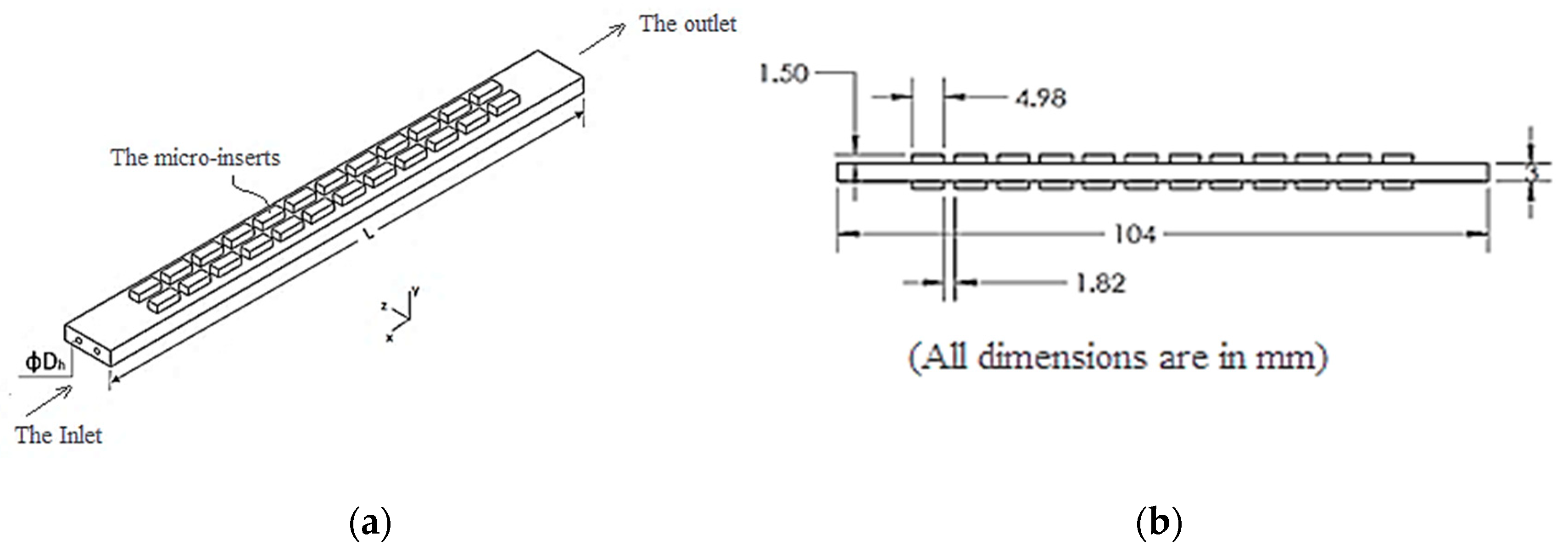
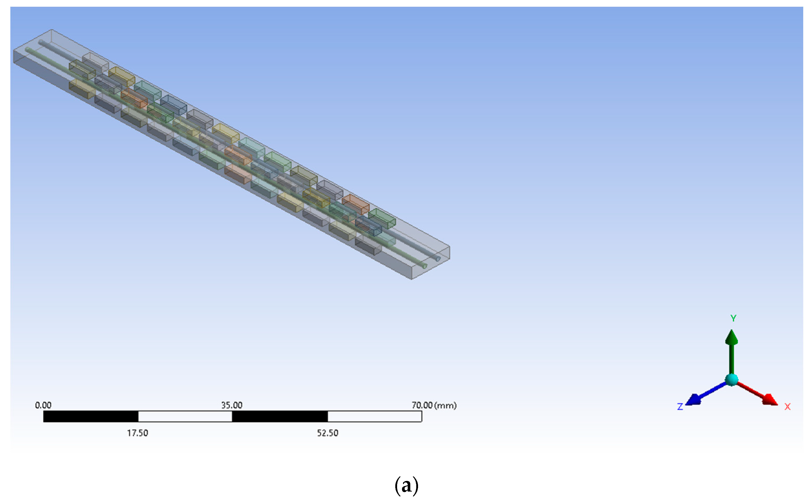
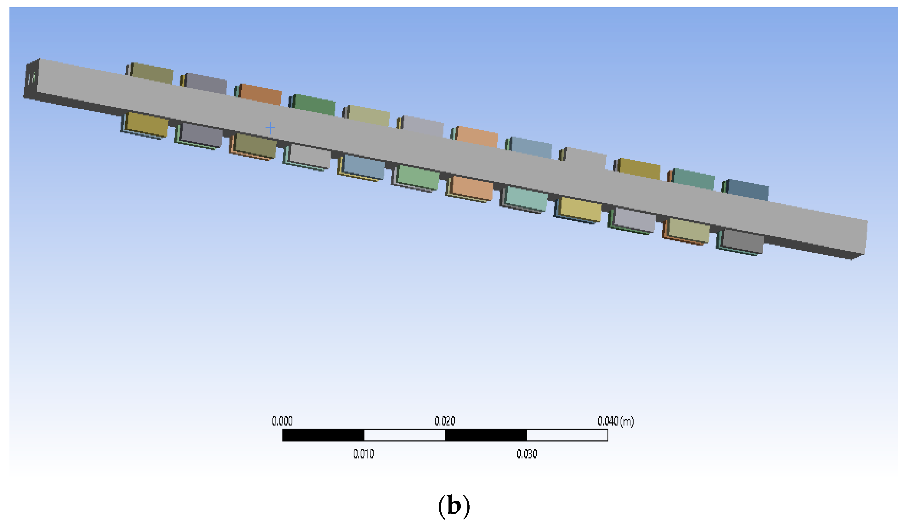
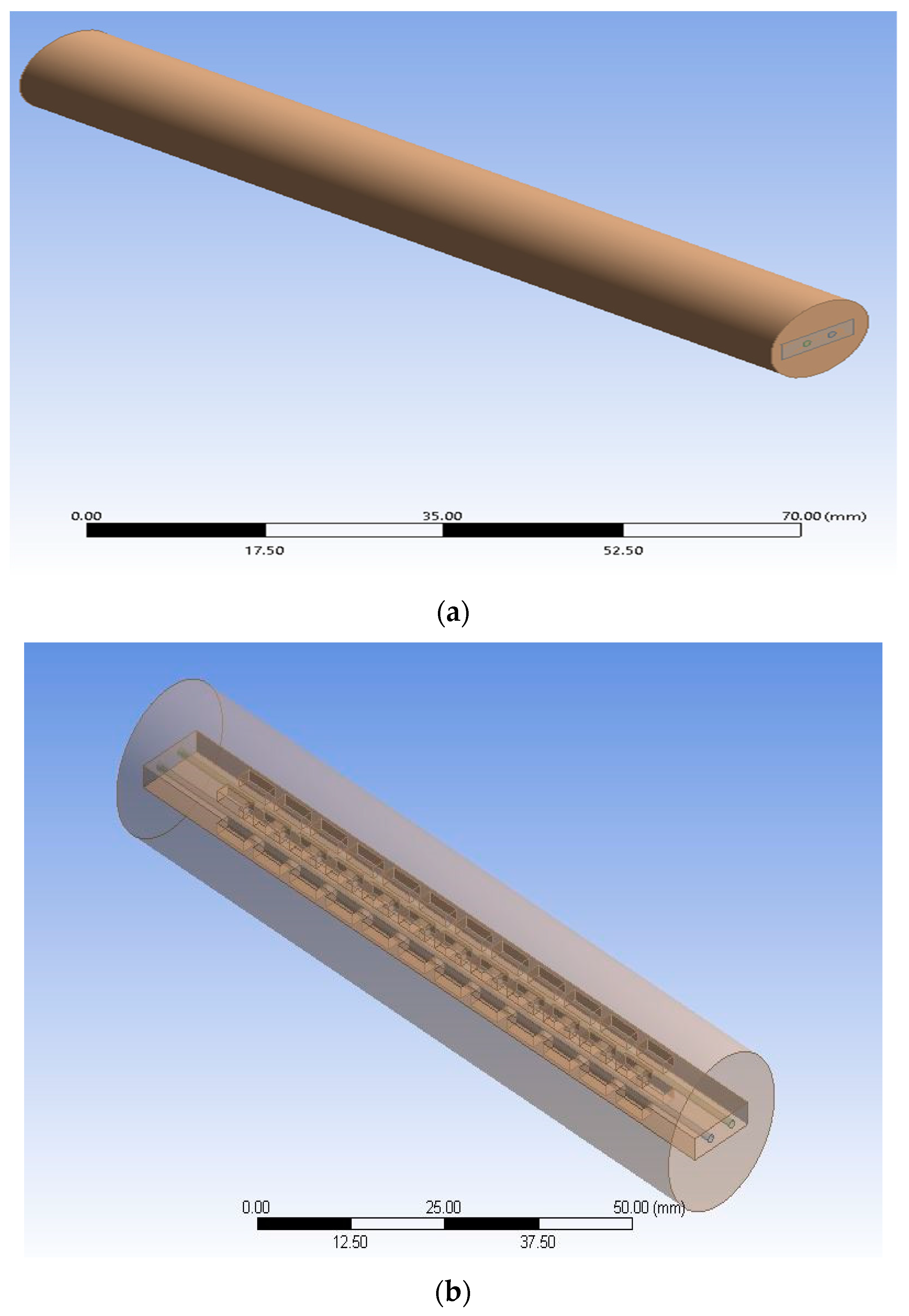
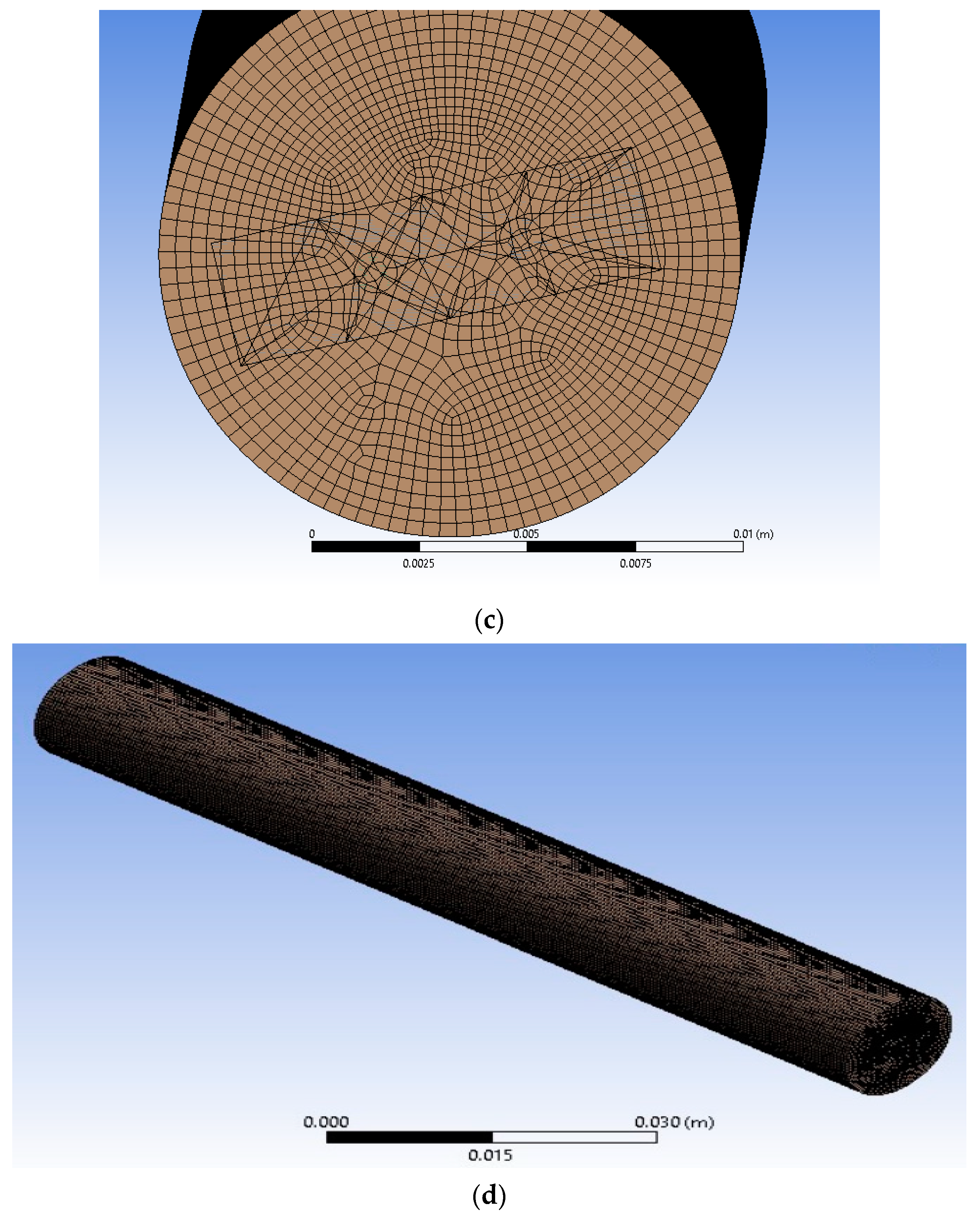
Figure 1 shows the schematic diagram of the simulated microchannel heat sink. The hydraulic diameter is represented by , while the length of the microchannel heat sink is represented by . The 3-D perspective of the microchannel model is displayed in Figure 2. The grids and computational domains used in the simulation are shown in Figure 3. As part of the numerical analysis, the computational domain was subjected to boundary conditions, and then the operations of meshing were performed. It was obvious that greater mesh counts produced very accurate results regardless of the analysis runtime.
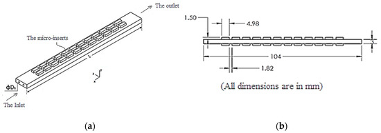
Figure 1.
(a) Schematic illustration of the simulated microchannel heat sink, (b) detailed dimensions of microchannel and microinserts.
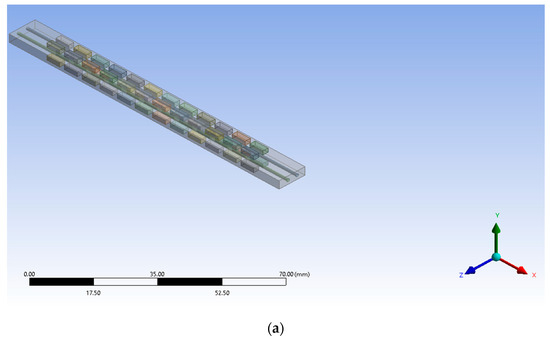
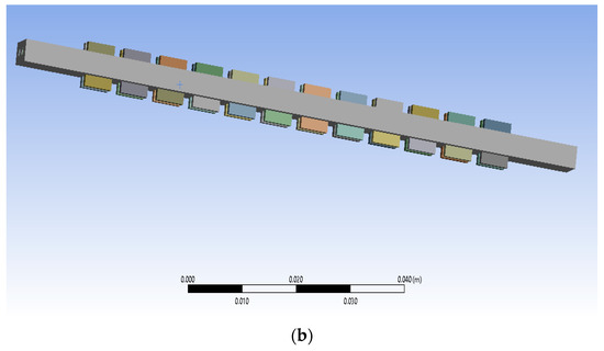
Figure 2.
The microchannel heat sink model in three dimensions: (a) top view, (b) isometric view.
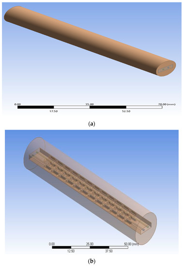
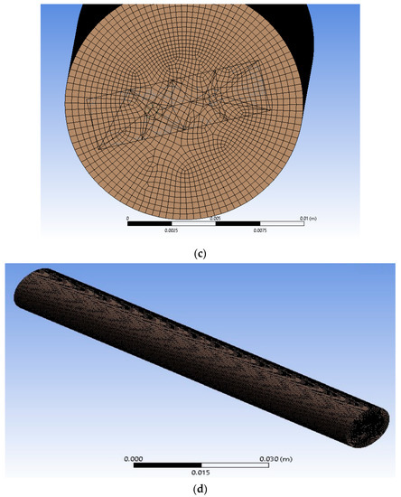
Figure 3.
Computational domains and grids used in the modeling of computational fluid dynamics. (a) Computational domains, (b) Computational domain model with micro-inserts, (c) Computational grids of edge of domain, (d) Computational grids used in the modeling of computational fluid dynamics.
2.3. Simulation Using Computational Fluid Dynamics (CFD) and Grid Independence Study
ANSYS [41] software was used in the current investigation to produce the numerical solutions. In contemplation of the error generated by grid coarseness, a grid independence test for the best grid was carried out to lessen the inaccuracy generated. Figure 3 displays the conventional x-y grid. Tetrahedral types of grids are employed for improved quality precision. The characteristics and attributes of the mesh are outlined in Table 1. The Cartesian grid approach was used for grid independence testing. In the current investigation, the grid independence testing was performed using four distinct grid numbers: 756456, 929682, 1043276, and 1145665.

Table 1.
The details of CFD modeling: mesh characteristics.
The outcome of the grid independence test demonstrated that the difference between the numerical solutions achieved for two different meshes was negligible. The rise in node counts was 2012 as the size of the mesh was increased from 1229781 to 1231793, with a negligible variance in the calculated solution of 0.016%. It was inferred that the accuracy of the solution did not significantly improve with increasing grid size due to the higher computing time and expense. There was no discernible difference in the results for mesh sizes of 1043276 and 1145665; as a consequence, a node size of 1229781 and mesh element number of 1043276 were chosen for computational modeling.
2.4. Performance Indicators
The parameters that were crucial for defining fluid flow and heat transfer in the microchannel were found using the simulation results. Different analytical parameters that characterize thermo-hydrodynamic features have been presented with the pertinent expressions in order to evaluate how well the microchannel performed.
The definition of the Reynolds number () is:
In this equation, (Pa-s) is the fluid’s dynamic viscosity, and (m/s) is the speed. At the microchannel inlet, stands for hydraulic diameter, which is expressed using as the microchannel’s width and as its height, as follows:
The following is the expression for the microchannel’s friction factor:
where (kg/m3) is the fluid’s observed density. The microchannel’s length, measured in mm, is . The pressure drop between the inlet and outlet of the microchannel is denoted by the symbol , where and are the pressures between the microchannel’s intake and its discharge, respectively.
The Nusselt number Nu is written as follows:
Here, the fluid’s observed thermal conductivity () is measured in W/m-K. is the fluid and microchannel’s contact surface area, which is measured in mm2, and is written as:
The thermal performance factor was utilized to examine the overall performance of the microchannel in order to determine its increased performance. The thermal performance factor, also known as the TPF, is a metric that is utilized in the process of evaluating the overall performance. This criterion is defined as the ratio of the increment in heat transmission to the increment in the friction factor [42]. Consequently, the TPF is stated as follows for a constant pump power:
2.5. Model Validation for Numerical Data
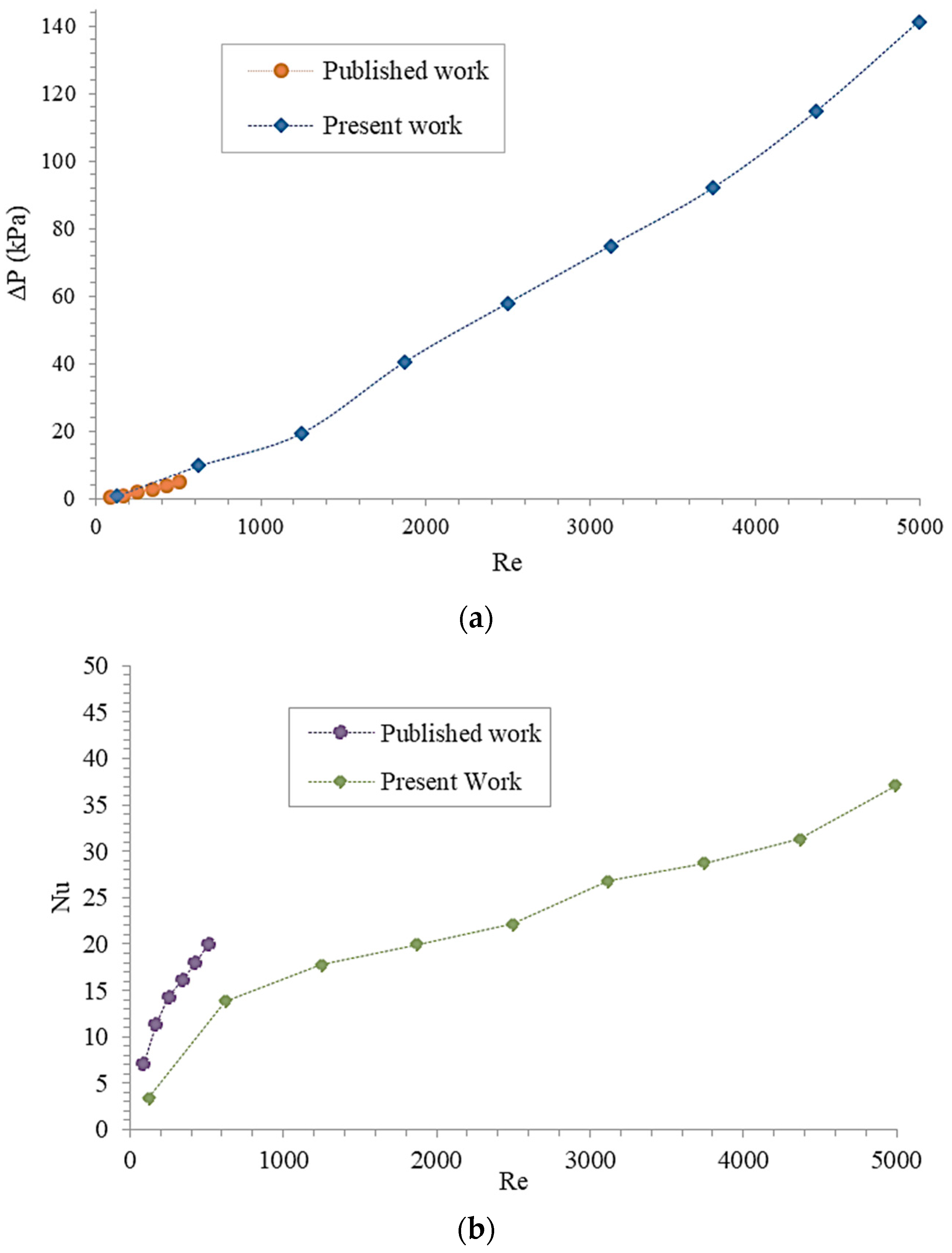
The suggested model’s validity must be checked and validated before moving on to the numerical simulation. The suggested model’s accuracy was confirmed by comparing the simulation results with those found in the literature (Figure 4). Data on Reynolds and Nusselt numbers were obtained from a previously published paper describing relevant experimental work [43]. The results from the simulation were found to be consistent with the published information. The pressure drop and Nusselt number exhibited the same pattern. This analysis demonstrated that the current suggested model was credible and supported the validity of the current model proposal.

Figure 4.
Validation of the proposed model’s consistency by comparing data obtained from present study with a previously published paper [43] (a) variation in pressure drop (∆P, kPa) versus Reynolds number (Re), (b) comparison of Nusselt number (Nu) versus Reynolds number (Re).
3. Results and Discussion
3.1. Pressure Drop Characteristics
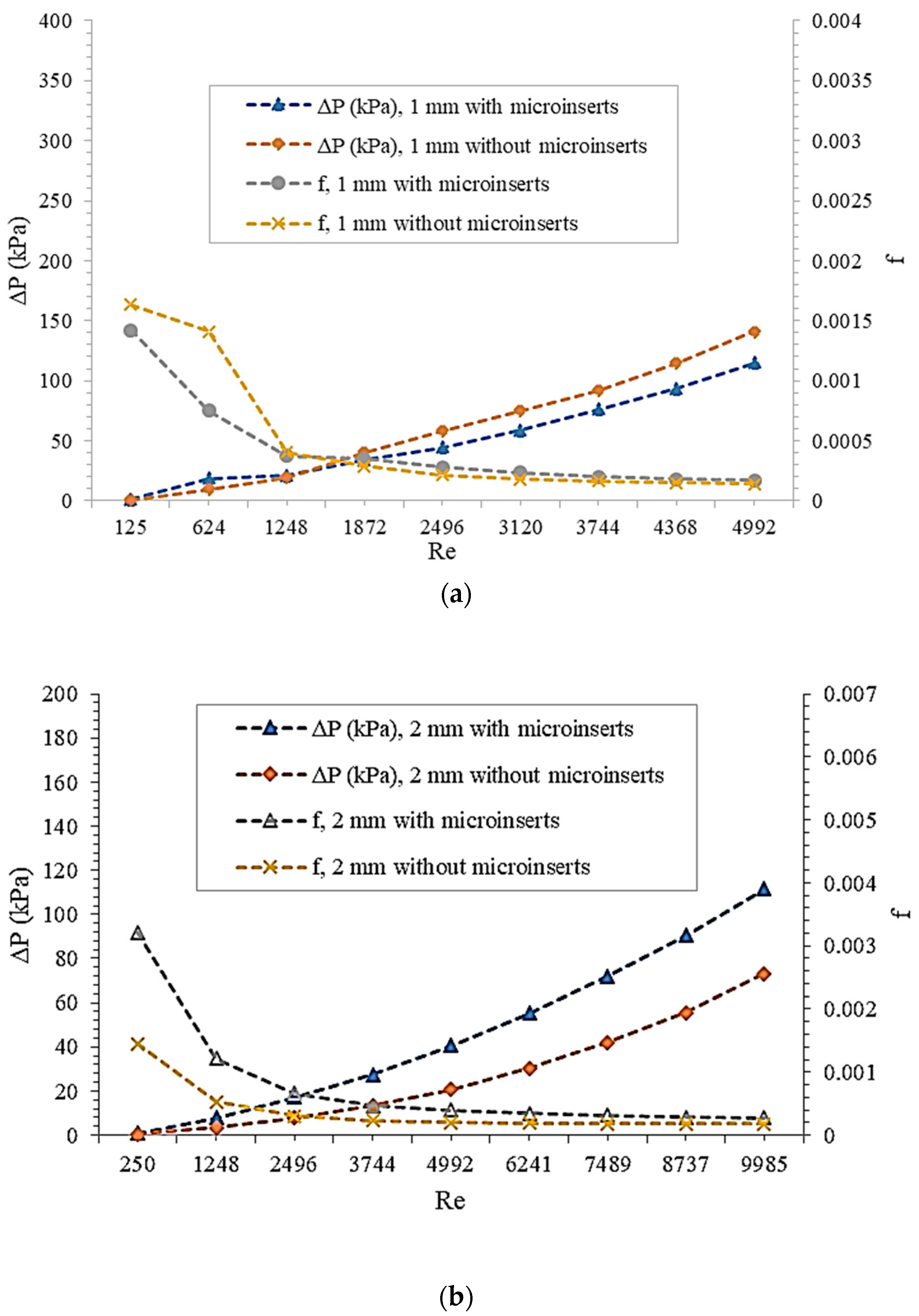
It was hypothesized that the working fluid would have some viscosity. Higher viscosity fluids encounter more pressure loss when they move through a channel because they offer more resistance to flow than less viscous fluids. Figure 5 shows how the pressure decreased and the friction factor varied with Reynolds number. With or without micro-inserts, the pressure drop was observed to rise approximately linearly with Reynolds number across all channel sizes. Due to the fact that higher temperatures decrease water’s viscosity, the pressure drop was less severe when the Reynolds number was low compared to when it was high. The maximum value of the pressure drop was recorded with a channel size of 1 mm.
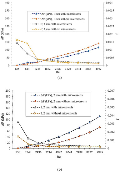
Figure 5.
Plot of the variation in pressure drop (∆P) and friction factor (f) against Reynolds number (Re) for (a) channel size of 1 mm; (b) 2 mm channel size. Each curve corresponds to either cases of channels with or without micro-inserts.
The pressure drop increased once micro-inserts were introduced. This was because adding micro-inserts to the microchannel made the structure more complicated, leading to a higher pressure drop. It was observed that introducing micro-inserts could increase the pressure drop in the 1 mm channel by a factor ranging from 0.53 to 1.31 and in the 2 mm channel by a factor ranging from 1.52 to 2.28. Adding micro-inserts while simultaneously decreasing the channel size raised the pressure drop. The design of a heat exchange system should steer clear of extremely high Reynolds numbers, as they almost always result in an undesired pressure drop. This pressure drop is a major contributor to rising energy costs and a hindrance to efficient heat exchange systems. Because of this, the inclusion of micro-inserts was most beneficial at low Reynolds numbers, when the resulting drop in pressure was negligible. This makes micro-insert insertion a potentially useful technique. Systems with low levels of frictional resistance perform better in terms of heat transmission.
It was found that for the 1 and 2 mm channel sizes, for Reynolds numbers between 125 and 1248 and between 1250 and 2496, respectively, the friction factor dropped more sharply with increasing Reynolds number. Integrating micro-inserts into microchannels was discovered to drastically alter the frictional resistance. It was determined that the 1 mm channel size produced the highest friction factor. As micro-inserts were inserted into the microchannel, the friction factor changed by a factor of 0.53 to 1.31 in the case of the 1 mm channel and by a factor of 1.52 to 2.27 in the case of the 2 mm channel. Because smaller channel diameters have shorter paths for fluid flow, the resistance to flow increased as the channel size decreased, which in turn increased the pressure drop and ultimately the amount of pumping power required. This was because for a given channel size, the resistance to fluid flow was highest in the narrowest of passages. In conclusion, changing the microchannel’s diameter or introducing micro-inserts can have a significant impact on the fluid’s pressure drop.
3.2. Heat Transfer Characteristics
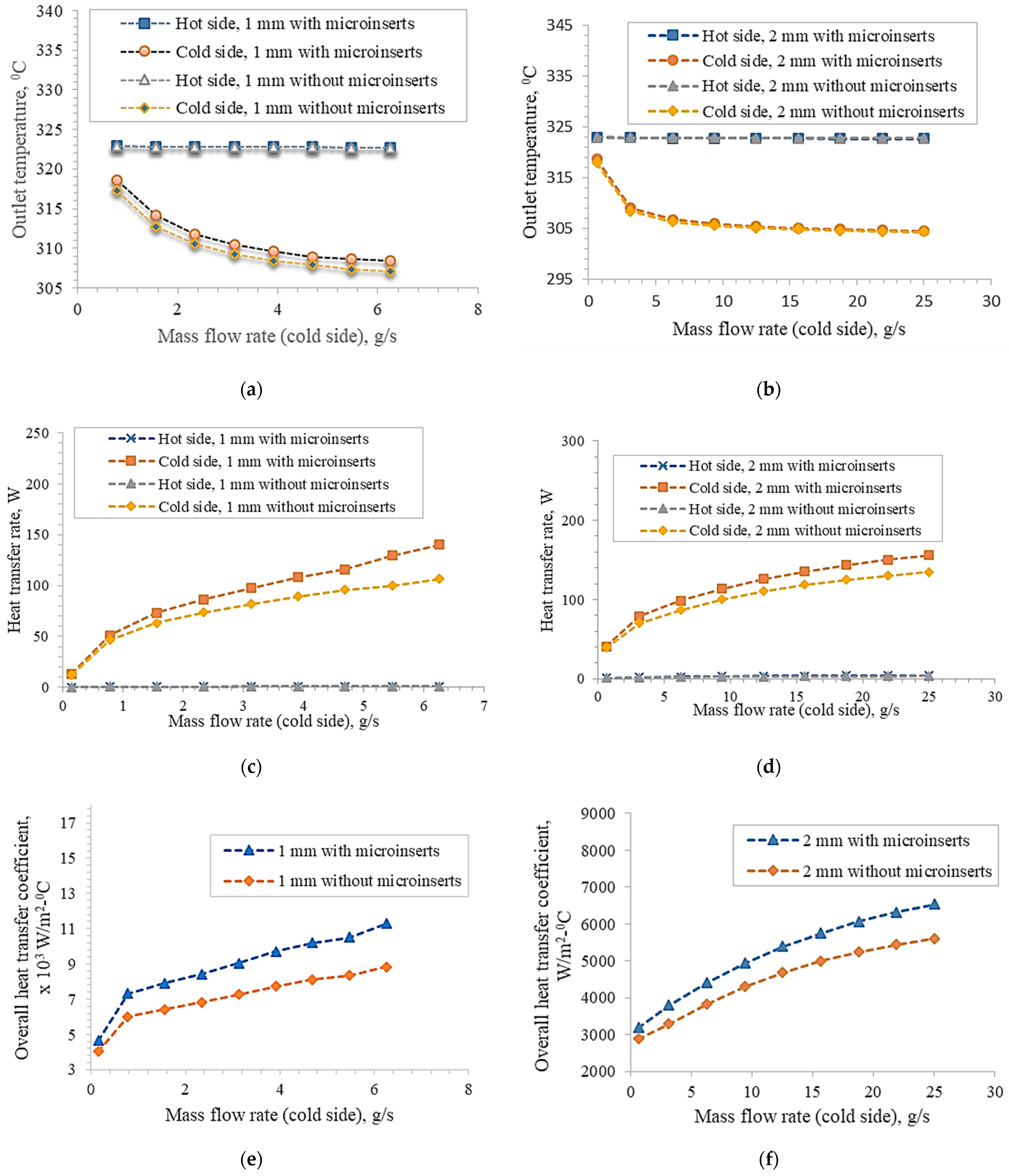
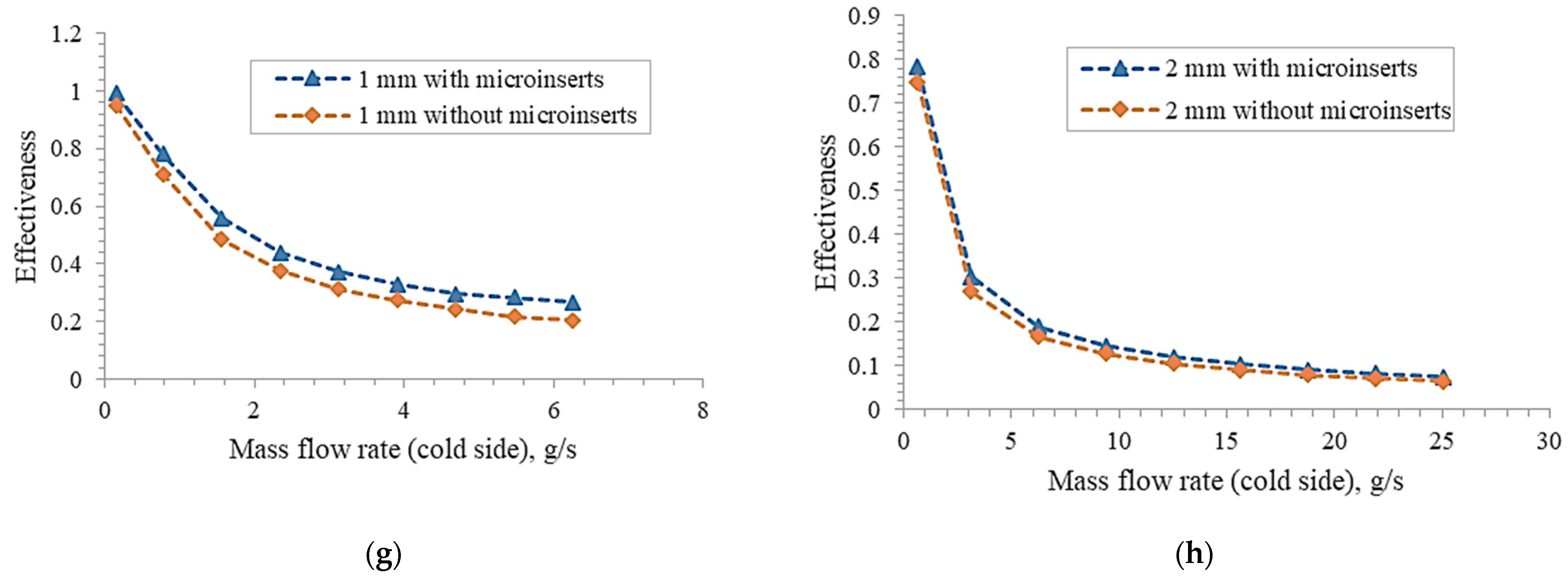
The overall heat transfer coefficient, the number of transfer units (NTU), the efficiency, and so on are all important aspects in determining the thermal performance of a heat exchange device. The variation in such thermal parameters in relation to the mass flow rate is represented in Figure 6. The cold input was maintained at 30 degrees Celsius, while the hot input was maintained at 50 degrees Celsius. A steady flow of mass of 0.782 g/s for the 1 mm channel and 3.127 g/s for the 2 mm channel was applied to the hotter side. Depending on the channel size, the mass flow was anywhere from 0.156 to 6.255 g/s for the 1 mm channel and from 0.625 to 25.02 g/s for the 2 mm channel. Figure 6 provides a side-by-side comparison of the results obtained from the experimental data gathered under the specified parameters of 1 and 2 mm. It was found that increasing the mass flow rate of the side with the lower temperature caused the outflow temperature to decrease. It was observed that the highest temperatures in channels with micro-inserts were lower than those in channels without them. This suggested that the channel’s heat transfer ability was enhanced by the addition of micro-inserts. Overall, the micro-insert-containing channels had substantially higher heat transfer coefficients than the non-micro-insert-containing channels for both channel diameters.
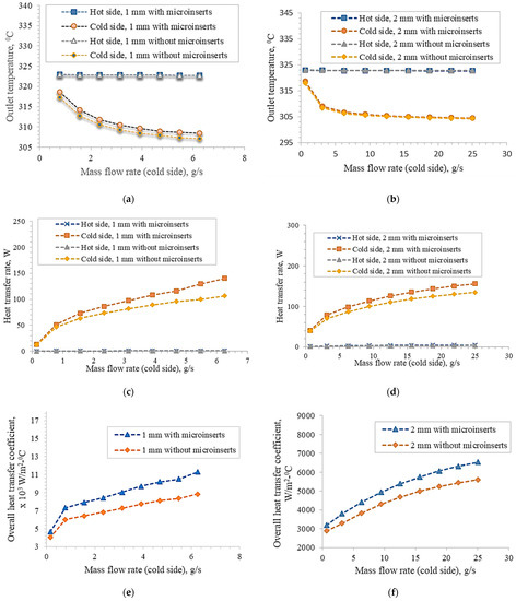
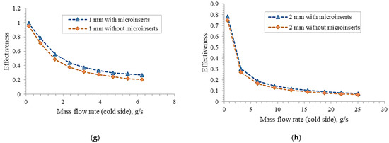
Figure 6.
An illustration of the relationship of different parameters with the mass flow rate. The plots of fluctuations of (a) outlet temperature against mass flow rate, (c) heat transfer rate against mass flow rate, (e) overall heat transfer rate against the mass flow rate, and (g) effectiveness against the mass flow rate are presented for a channel size of 1 millimetre. For a channel with a diameter of 2 mm, the following relationships are presented: (b) outlet temperature as a function of mass flow rate; (d) heat transfer rate as a function of mass flow rate; (f) overall heat transfer rate as a function of the mass flow rate; and (h) effectiveness as a function of the mass flow rate.
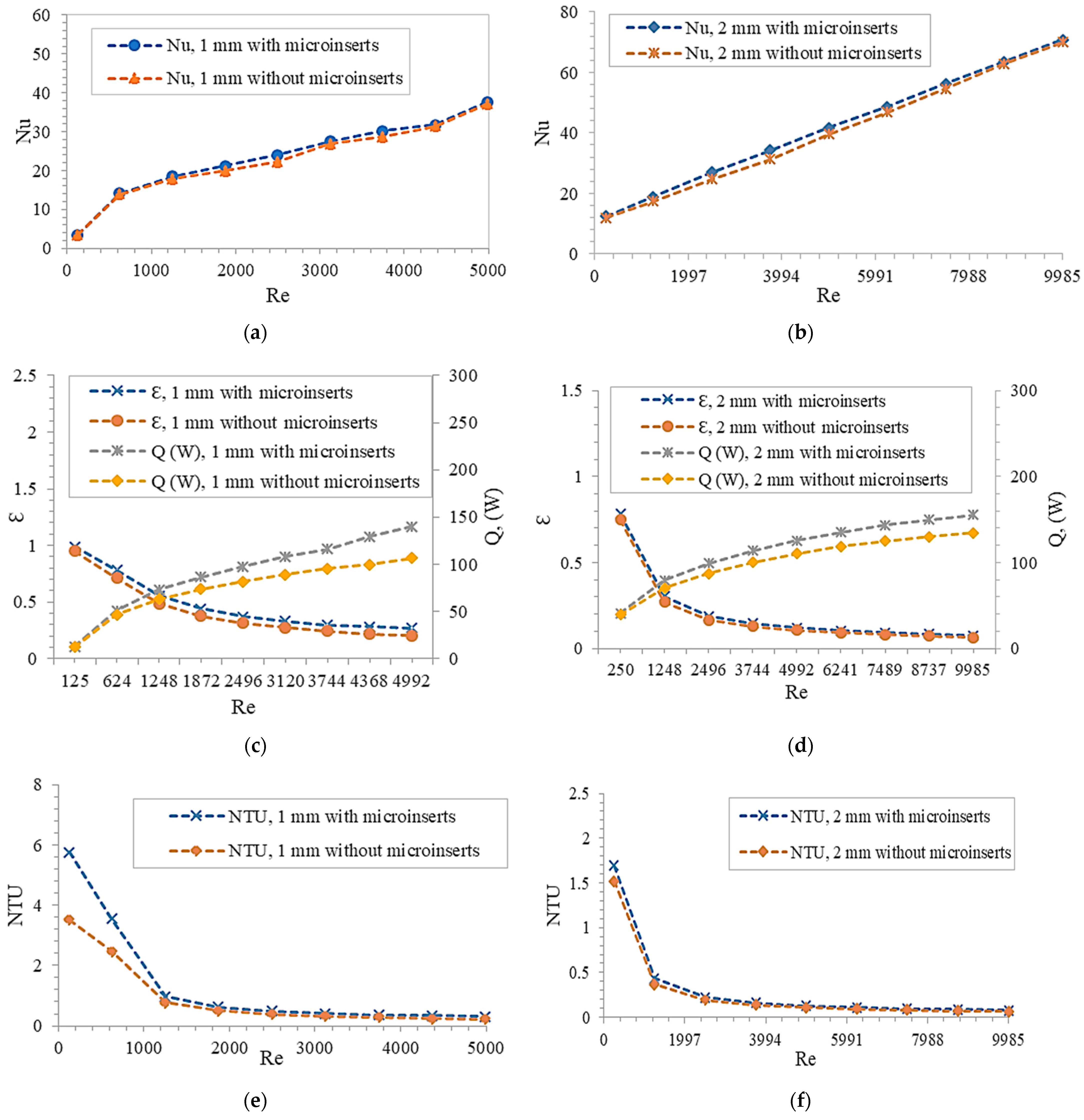
Figure 7 depicts the effect of increasing the Reynolds number on the Nusselt number in microchannels of varied sizes with and without micro-inserts. It was reasonable to anticipate that the Nusselt number would rise as the Reynolds number rose. This was to be expected. A high Nusselt number indicates that the microchannel is an efficient heat sink. The heat transfer rate was intensified by a factor of 1.01–1.08 and 0.99–1.08 when micro-inserts were added to the 1 and 2 mm channels, respectively. It was discovered that the Nusselt number rose by 8% for the 1 mm microchannel with micro-inserts having an Re value of 2496. In contrast to the microchannel without micro-inserts, the microchannel with micro-inserts had a higher Nusselt number, indicating superior heat transmission performance. The Nusselt number increased rapidly with the Reynolds number at first, but thereafter it flattened off for the 1 mm channel size. In accordance with this, the rate of heat transfer between the channel wall and fluid was quite high in the beginning, but then it progressively dropped off until it reached a steady state. This demonstrated that for lower Reynolds numbers, a drastic reduction of the temperature difference between the channel wall and fluid occurred, while at high Reynolds numbers, the difference diminished more gradually. For the narrower channels, the relationship between the Nusselt and Reynolds numbers had a sharper slope, whereas for the wider channels, the slope was flatter. This showed that a significant enhancement in heat transfer could be gained by reducing the channel size. The improved heat transfer capabilities could be attributed to the increased flow disturbances and bigger convective zone. The effect of the micro-inserts on the improvement of heat transmission was found to be attenuated at the two extremes of the Reynolds number ranges. When the Reynolds number fell between the medium bands, the insertion of micro-inserts significantly improved the thermal performance. The reason was that at high Reynolds numbers, effective heat transmission was impeded as opposed to what occurred at moderate Reynolds numbers. Micro-inserts placed in the microchannel boosted the structure’s capacity to conduct heat. It was discovered that inserting micro-inserts was the most efficient way to increase the Nusselt number since it was raised by a factor of 1.00–1.08 in the Reynolds number range of 560–2242 for the channel diameter of 1 mm. Micro-inserts facilitated heat transfer enhancement by producing disruptions in the thermal boundary layer and causing heat to be distributed more uniformly. As a result, micro-inserts added to the microchannel allowed for more rapid and effective heat exchange. Micro-inserts inserted into the microchannel allowed for improved heat transmission while simultaneously raising flow resistance. Because of the micro-inserts and the narrower channel, heat flow was greatly enhanced, and the heating surface became much more manageable and less scorching hot. Micro-inserts offer a promising method to improve heat transfer in channels of varying diameters. Additionally, since micro-inserts permit a greater rate of heat transfer, their importance grows as the channel size decreases. This is because thermo-physical features had a greater influence over thermal transfer at the narrower diameter. Feng et al. (2017) [11] demonstrated that the introduction of an insert significantly influenced the improvement of heat transmission. According to their findings, the microchannel’s sensitivity to temperature was crucial for making such findings.
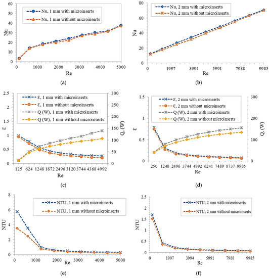
Figure 7.
An illustration of the relationship between various thermal parameters and the Reynolds number. (a,b) Plots of the fluctuations of Nusselt number with Reynolds number for channel sizes of 1 and 2 mm, respectively. (c,d) Plots of the variations in the efficacy and heat transfer rate with varying Reynolds number for the corresponding channels with 1 and 2 mm diameters. (e,f) Plots of the fluctuations in the number of transfer units plotted against the Reynolds number for channels with sizes of 1 and 2 mm, respectively.
3.3. Thermal Performance Factor
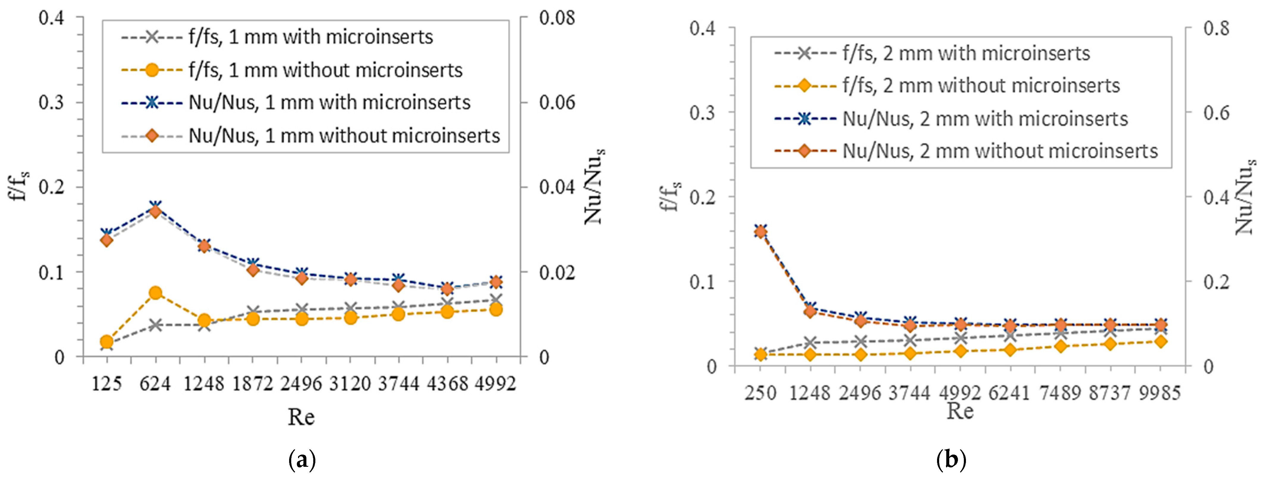
Improved thermal performance was observed alongside an increase in flow resistance due to the narrower channel and the incorporation of micro-inserts, as revealed by the study’s findings. An increase in the efficiency of heat transmission would be helpful, even though a larger pressure drop was not something that was desired. The trade-off between enhanced thermal performance and increased pressure drop was established by evaluating the channel’s entire performance using the criterion of the thermal performance factor (TPF). The thermal performance factor reflects how rapidly heat is transmitted in response to an increase in friction. Figure 8 shows how f/fs and Nu/Nus changed with respect to Re. As the Reynolds number increased, the f/fs values were shown to increase. Regardless of the channel size, the f/fs ratio increased with the inclusion of micro-inserts except at lower Reynolds numbers in the case of the 1 mm channel. This behavior was predicted by the influence of temperature on fluid viscosity. A significant increase in f/fs was seen at low Reynolds numbers for the smaller channels. This may have been because the boundary layer was disturbed more frequently.
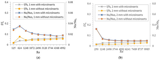
Figure 8.
An illustration of the relationship between the friction factor ratio and the Nusselt number factor with the Reynolds number for (a) 1 mm channel size and (b) 2 mm channel size.
Figure 9 shows the variation of Nu/Nus with Reynolds number. It was found that the Nu/Nus ratio consistently fell with rising Reynolds number, with one exception: at low Reynolds numbers, the variation behaved differently. The Nu/Nus ratios for the 1 mm channels first grew significantly and then declined continuously for all Reynolds numbers. Whereas in the 2 mm scenario, there was an initial abrupt drop followed by a gradual fall as the Reynolds number increased.
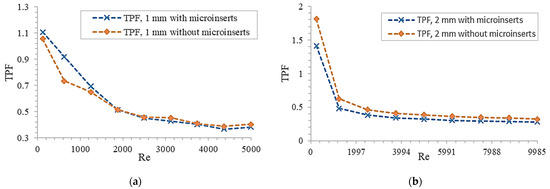
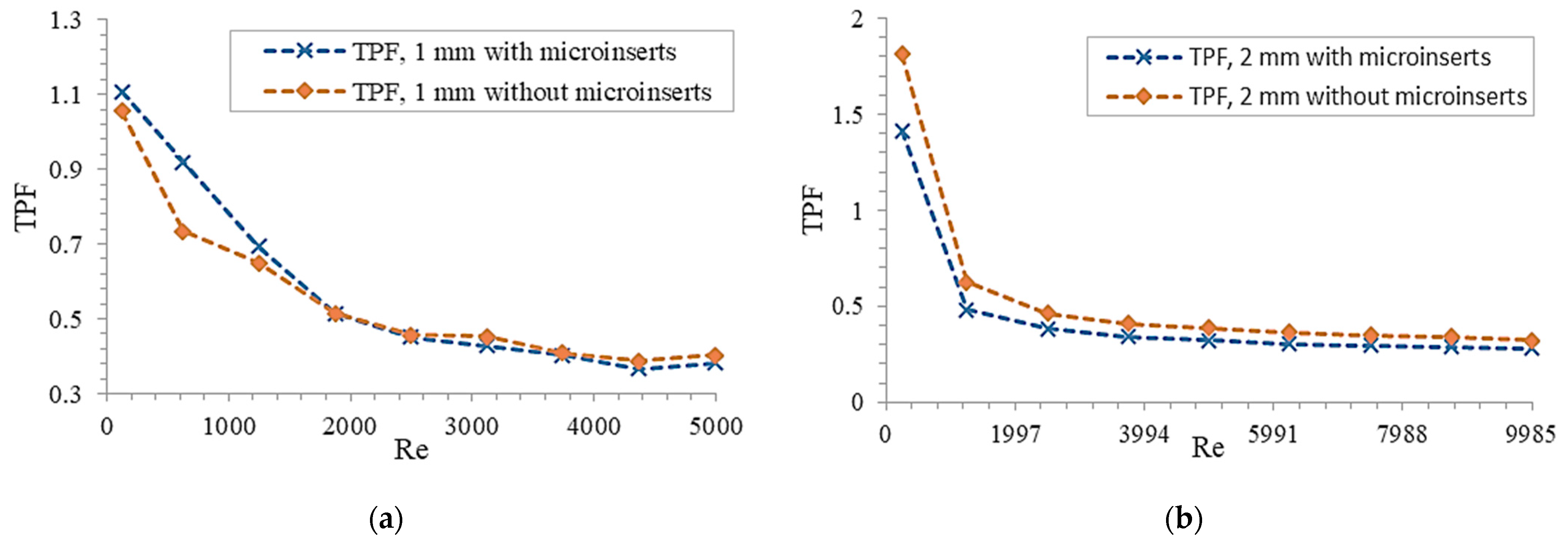
Figure 9.
An illustration of the relationship between the thermal friction factor and the Reynolds number for (a) 1 mm channel size and (b) 2 mm channel size.
Microchannels of varying sizes with micro-inserts were simulated and their resulting thermal performance factor values as a function of Reynolds number are shown in Figure 9. The results showed that the TPF decreased as the Reynolds number rose. For the larger channel size, the rate of decrease in TPF was steeper at low Reynolds numbers, whereas it flattened off at high Reynolds numbers. The reason for this pattern was that for smaller Reynolds numbers, the pressure drop rate was larger than the heat transfer rate. As the Reynolds number increased, the flow loss became less of a factor, and the TPF decreased regardless of the value of the Reynolds number. There was a wide variation in TPF values across different channel sizes, from 0.95 to 1.25 for the 1 mm channels and from 0.77 to 0.87 for the 2 mm channels. The TPF of the 1 or 2 mm channels was found to decrease monotonically as the Reynolds number rose. After a particular Reynolds number, pressure loss overtook heat transmission, although up to that point, the trend may have continued indefinitely. At higher Reynolds numbers, it was discovered that channels containing micro-inserts had TPF values that were lower than those of channels that did not contain micro-inserts. When trying to minimize the channel size, the TPF values for channels with micro-inserts were more crucial than those for channels without them. The thermal performance of the narrower diameter channel was superior for small Reynolds numbers, while increased flow resistance was more pronounced at high Reynolds numbers. When the Reynolds numbers were low, the benefit of adding micro-inserts to the narrower channel for heat transfer enhancement was more obvious than when the Reynolds numbers were high. A microchannel’s overall performance may be improved by reducing the channel size and incorporating micro-inserts into the design at low Reynolds numbers.
Low-flow-resistance, high-performance microchannel heat sinks are in high demand for numerous technological applications in various industries. The current findings are relevant to industries that require the removal of heat from a restricted space at a very high rate utilizing passive techniques of heat removal, in particular, microchannel heat exchangers. The findings can be used by industries to improve the longevity of many different types of electronic devices, including laptops, supercomputers, CNC machines, medical instruments such as MRI scanners, etc., by optimizing the thermal performance, fluid flow behavior, and overall performance of the newly proposed microchannel designs.
4. Conclusions
This paper numerically investigated how different microchannel heat exchanger sizes and the presence or absence of micro-inserts affected their thermo-hydraulic features. Pressure drop measurements, Nusselt numbers for heat transmission, and the thermal performance factor were all used to evaluate microchannel performance. The numerical simulation was carried out using ANSYS with water serving as the working fluid for Reynolds number ranges of 125–4992 and 250–9985 for 1 and 2 mm channel diameters, respectively. The coupled heat transport model was used.
- The thermo-hydrodynamic characteristics were found to be considerably influenced by diameter size variation and the presence of micro-inserts.
- The insertion of micro-inserts significantly improved heat transmission, with boosts of 8.1% for the 1 mm channel and 9.4% for the 2 mm channel, respectively.
- When it comes to flow loss, the small channel with micro-inserts increased the flow resistance at lower Reynolds numbers, resulting in a greater pressure decrease and consequently needing higher pump power.
- The results illustrated that it is crucial to assess the entire performance of a microchannel by taking both flow loss and thermal performance into account.
- The overall performance of the microchannel heat exchanger was enhanced by the addition of micro-inserts and a smaller channel size at smaller Reynolds numbers owing to the reduced pressure loss.
Insights from this investigation may be utilized to optimize the design of microchannel cooling systems with restrictions such as constant Reynolds numbers. Simulation of microchannels using CFD was performed. One of the benefits of this model is that it required less computational time to run than other simulation methods referenced in the literature. One of the model’s flaws is that it did not account for nonlinear behavior.
There is a lot of opportunity for further developments in microchannel heat exchanger design and application, including the use of micro-inserts of varied shapes and sizes, reduction of microchannel size, alteration of the working fluid, and so on. Micro-inserts allow for heat transfer optimization across a broad range of channel diameters. In addition, the importance of micro-inserts increases with decreasing channel size because of the possible enhancement of heat transfer. By further reducing the channel diameter, additional analysis can be conducted.
Author Contributions
Conceptualization, S.R.K. and S.S.; methodology, S.R.K.; software, S.R.K.; validation, S.R.K.; formal analysis, S.R.K.; investigation, S.R.K.; resources, S.R.K.; data curation, S.S.; writing—original draft preparation, S.R.K.; writing—review and editing, S.S.; visualization, S.R.K.; supervision, S.S.; project administration, S.S. All authors have read and agreed to the published version of the manuscript.
Funding
This research received no external funding.
Data Availability Statement
Not applicable.
Conflicts of Interest
The authors declare no conflict of interest.
Nomenclature
| Symbols | Descriptions | Unit |
| As | Contact surface area of the fluid and microchannel | mm2 |
| CFD | Computational fluid dynamics | |
| cp | Specific heat of water | J/kg-K |
| Dh | Hydraulic diameter | mm |
| f | Friction factor | |
| H | Height of the microchannel | mm |
| h | Heat transfer coefficient | W/m2-K |
| kf | Thermal conductivity of fluid | J/s-m-K |
| Ks | Solid thermal conductivity | J/s-m-K |
| L | Length of the microchannel | mm |
| m | Mass | kg |
| Nu | Nusselt number | |
| p | Pressure | Pa |
| Re | Reynolds Number | |
| T | Temperature | K |
| TPF | Thermal performance factor | |
| U | Fluid velocity | m/s |
| W | Width of the microchannel | mm |
| Δp | Pressure difference | |
| ΔT | Temperature difference | |
| Greek symbols | ||
| ρ | Fluid density | Kg/m3 |
| µ | Dynamic viscosity | Pa-s |
| Subscript | ||
| f | Fluid | |
| s | Solid |
References
- Abdoli, A.; Jimenez, G.; Dulikravich, G.S. Thermo-fluid analysis of micro pin-fin array cooling configurations for high heat fluxes with a hot spot. Int. J. Therm. Sci. 2015, 90, 290–297. [Google Scholar] [CrossRef]
- Pan, X.; Hong, X.; Xu, L.; Li, Y.; Yan, M.; Mai, L. On-chip micro/nano devices for energy conversion and storage. Nano Today 2019, 28, 100764. [Google Scholar] [CrossRef]
- Tuckerman, D.B.; Pease, R.F.W. High-Performance Heat Sinking for VLSI. IEEE Electron Device Lett. 1981, 2, 126–129. [Google Scholar] [CrossRef]
- Meyari, M.; Salehi, Z.; Zarghami, R.; Saeedipour, M. Numerical investigation of particle separation in Y-shaped bifurcating microchannels. Particuology 2021, 56, 142–151. [Google Scholar] [CrossRef]
- Ling, W.; Zhou, W.; Liu, C.; Zhou, F.; Yuan, D.; Huang, J. Structure and geometric dimension optimization of interlaced microchannel for heat transfer performance enhancement. Appl. Therm. Eng. 2020, 170, 115011. [Google Scholar] [CrossRef]
- Rabiei, S.; Khosravi, R.; Bahiraei, M.; Raziei, M.; Hosseini, A.A. Thermal and hydraulic characteristics of a hybrid nanofluid containing graphene sheets decorated with platinum through a new wavy cylindrical microchannel. Appl. Therm. Eng. 2020, 181, 115981. [Google Scholar] [CrossRef]
- Sohel, M.; De Castro, C.N. A critical review of traditional and emerging techniques and fluids for electronics cooling. Renew. Sustain. Energy Rev. 2017, 78, 821–833. [Google Scholar] [CrossRef]
- Dixit, T.; Ghosh, I. Review of micro- and mini-channel heat sinks and heat exchangers for single phase fluids. Renew. Sustain. Energy Rev. 2015, 41, 1298–1311. [Google Scholar] [CrossRef]
- Saha, S.K.; Agrawal, A.; Soni, Y. Heat transfer characterization of rhombic microchannel for H1 and H2 boundary conditions. Int. J. Therm. Sci. 2017, 111, 223–233. [Google Scholar] [CrossRef]
- Omar, P.J.; Gaur, S.; Dikshit, P.K.S. Conceptualization and development of multi-layered groundwater model in transient condition. Appl. Water Sci. 2021, 11, 162. [Google Scholar] [CrossRef]
- Omar, P.J. Geomatics techniques-based significance of morphometric analysis in prioritization of watershed. Int. J. Enhanc. Res. Sci. Technol. Eng. 2015, 4, 13–24. [Google Scholar]
- Omar, P.J.; Shivhare, N.; Dwivedi, S.B.; Dikshit, P.K.S. Identification of soil erosion-prone zone utilizing geo-informatics techniques and WSPM model. Sustain. Water Resour. Manag. 2022, 8, 66. [Google Scholar] [CrossRef]
- Kumar, V.; Chaplot, B.; Omar, P.J.; Mishra, S.; Azamathulla, M.H. Experimental study on infiltration pattern: Opportunities for sustainable management in the Northern region of India. Water Sci. Technol. 2021, 84, 2675–2685. [Google Scholar] [CrossRef] [PubMed]
- Wang, C.S.; Wei, T.C.; Shen, P.Y.; Liou, T.M. Lattice Boltzmann study of flow pulsation on heat transfer augmentation in a louvered microchannel heat sink. Int. J. Heat Mass Transf. 2020, 148, 119139. [Google Scholar] [CrossRef]
- Alihosseini, Y.; Zabetian, M.; Mohammad, T.; Heyhat, M. Thermo-hydraulic performance of wavy microchannel heat sink with oblique grooved finned. Appl. Therm. Eng. 2021, 189, 116719. [Google Scholar] [CrossRef]
- Wang, H.; Chen, Z.; Gao, J. Influence of geometric parameters on flow and heat transfer performance of micro-channel heat sinks. Appl. Therm. Eng. 2016, 107, 870–879. [Google Scholar] [CrossRef]
- Gao, J.; Hu, Z.; Yang, Q.; Liang, X.; Wua, H. Fluid flow and heat transfer in microchannel heat sinks: Modelling review and recent progress. Therm. Sci. Eng. Prog. 2022, 29, 101203. [Google Scholar] [CrossRef]
- Mohammed, A.; Mohd-Ghazali, N.; Ahmad, R. Thermal and hydrodynamic analysis of microchannel heat sinks: A review. Renew. Sustain. Energy Rev. 2013, 21, 614–622. [Google Scholar] [CrossRef]
- Osanloo, B.; Mohammadi-Ahmar, A.; Solati, A.; Baghani, M. Performance enhancement of the double-layered microchannel heat sink by use of tapered channels. Appl. Therm. Eng. 2016, 102, 1345–1354. [Google Scholar] [CrossRef]
- Ali, A.M.; Ron, A.; Kadhim, H.T.; Angelino, M.; Gao, S. Thermo-hydraulic performance of a circular microchannel heat sink using swirl flow and nanofluid. Appl. Therm. Eng. 2021, 191, 116817. [Google Scholar] [CrossRef]
- Abdollahi, A.; Norris, S.E.; Sharma, R.N. Fluid flow and heat transfer of liquid-liquid Taylor flow in square microchannels. Appl. Therm. Eng. 2020, 172, 115123. [Google Scholar] [CrossRef]
- Liang, J.; Engelbrecht, K.; Nielsen, K.K.; Loewe, K.; Vieyra, H.; Barcza, A.; Bahl, C.R.H. Performance assessment of a triangular microchannel active magnetic regenerator. Appl. Therm. Eng. 2021, 186, 116519. [Google Scholar] [CrossRef]
- Burk, B.E.; Grumstrup, T.P.; Bevis, T.A.; Kotovsky, J.; Bandhauer, T.M. Computational examination of two-phase microchannel heat transfer correlations with conjugate heat spreading. Int. J. Heat Mass Transf. 2019, 132, 68–79. [Google Scholar] [CrossRef]
- Su, L.; Duan, Z.; He, B.; Ma, H.; Ning, X.; Ding, G.; Cao, Y. Heat transfer characteristics of thermally developing flow in rectangular microchannels with constant wall temperature. Int. J. Therm. Sci. 2020, 155, 106412. [Google Scholar] [CrossRef]
- He, W.; Mashayekhi, R.; Toghraie, D.; Akbari, O.A.; Li, Z.; Tlili, I. Hydrothermal performance of nanofluid flow in a sinusoidal double layer microchannel in order to geometric optimization. Int. Commun. Heat Mass Transf. 2020, 117, 104700. [Google Scholar] [CrossRef]
- Kewalramani, G.V.; Agrawal, A.; Saha, S.K. Modeling of microchannel heat sinks for electronic cooling applications using volume averaging approach. Int. J. Heat Mass Transf. 2017, 115, 395–409. [Google Scholar] [CrossRef]
- Soleimani, A.; Sattari, A.; Hanafizadeh, P. Thermal analysis of a microchannel heat sink cooled by two-phase flow boiling of Al2O3 HFE-7100 nanofluid. Therm. Sci. Eng. Prog. 2020, 20, 100693. [Google Scholar] [CrossRef]
- Shen, H.; Zhang, Y.; Wang, C.C.; Xie, G. Comparative study for convective heat transfer of counter-flow wavy double-layer microchannel heat sinks in staggered arrangement. Appl. Therm. Eng. 2018, 137, 228–237. [Google Scholar] [CrossRef]
- Li, X.Y.; Wang, S.L.; Wang, X.-D.; Wang, T.-H. Selected porous-ribs design for performance improvement in double-layered microchannel heat sinks. Int. J. Therm. Sci. 2019, 137, 616–626. [Google Scholar] [CrossRef]
- Derakhshanpour, K.; Kamali, R.; Eslami, M. Effect of rib shape and fillet radius on thermal-hydrodynamic performance of microchannel heat sinks: A CFD study. Int. Commun. Heat Mass Transf. 2020, 119, 104928. [Google Scholar] [CrossRef]
- Bin, F.; Hasis, A.; Krishna, P.M.M.; Aravind, G.P.; Deepu, M.; Shine, S.R. Thermo hydraulic performance analysis of twisted sinusoidal wavy microchannels. Int. J. Therm. Sci. 2018, 128, 124–136. [Google Scholar]
- Lu, G.; Zhai, X. Analysis on heat transfer and pressure drop of a microchannel heat sink with dimples and vortex generator. Int. J. Therm. Sci. 2019, 145, 105986. [Google Scholar] [CrossRef]
- Feng, Z.; Ai, X.; Wua, P.; Lin, Q.; Huang, Z. Experimental investigation of laminar flow and heat transfer characteristics in square minichannels with twisted tapes. Int. J. Heat Mass Transf. 2020, 158, 119947. [Google Scholar] [CrossRef]
- Khoshvaght-Aliabadi, M.; Sahamiyan, M. Performance of nanofluid flow in corrugated minichannels heat sink (CMCHS). Energy Convers. Manag. 2016, 108, 297–308. [Google Scholar] [CrossRef]
- Ma, Y.; Liu, C.E.J.; E, J.; Mao, X.; Yu, Z. Research on modeling and parameter sensitivity of flow and heat transfer process in typical rectangular microchannels: From a data-driven perspective. Int. J. Therm. Sci. 2022, 172, 107356. [Google Scholar] [CrossRef]
- Bhandari, P.; Rawat, K.S.; Prajapati, Y.K.; Padalia, D.; Ranakoti, L.; Singh, T. Design modifications in micro pin fin configuration of microchannel heat sink for single phase liquid flow: A review. J. Energy Storage 2023, 66, 107548. [Google Scholar] [CrossRef]
- Hajialibabaei, M.; Saghir, M.Z. A critical review of the straight and wavy microchannel heat sink and the application in lithium-ion battery thermal management. Int. J. Thermofluids 2022, 14, 100153. [Google Scholar] [CrossRef]
- Koo, J.; Kleinstreuer, C. Liquid flow in microchannels: Experimental observations and computational analyses of microfluidics effects. J. Micromech. Microeng. 2003, 13, 568–579. [Google Scholar] [CrossRef]
- Feng, Z.; Luo, X.; Guo, F.; Li, H.; Zhang, J. Numerical investigation on laminar flow and heat transfer in rectangular microchannel heat sink with wire coil inserts. Appl. Therm. Eng. 2017, 116, 597–609. [Google Scholar] [CrossRef]
- Chai, L.; Xia, G.; Zhou, M.; Li, J.; Qi, J. Optimum thermal design of interrupted microchannel heat sink with rectangular ribs in the transverse microchambers. Appl. Therm. Eng. 2013, 51, 880–889. [Google Scholar] [CrossRef]
- Ansys® Academic Research Mechanical and CFD. Help System, Coupled Field Analysis Guide; ANSYS, Inc.: Canonsburg, PA, USA, 2011. [Google Scholar]
- Webb, R.L. Performance evaluation criteria for use of enhanced heat transfer surfaces in heat exchanger design. Int. J. Heat Mass Transf. 1981, 24, 715–726. [Google Scholar] [CrossRef]
- Ling, W.; Zhou, W.; Yu, W.; Zhou, F.; Chen, J.; Hui, K.S. Experimental investigation on thermal and hydraulic performance of microchannels with interlaced configuration. Energy Convers. Manag. 2018, 174, 439–452. [Google Scholar] [CrossRef]
Disclaimer/Publisher’s Note: The statements, opinions and data contained in all publications are solely those of the individual author(s) and contributor(s) and not of MDPI and/or the editor(s). MDPI and/or the editor(s) disclaim responsibility for any injury to people or property resulting from any ideas, methods, instructions or products referred to in the content. |
© 2023 by the authors. Licensee MDPI, Basel, Switzerland. This article is an open access article distributed under the terms and conditions of the Creative Commons Attribution (CC BY) license (https://creativecommons.org/licenses/by/4.0/).